1
GE Limitamp® Medium Voltage Motor Control
Application Data
H
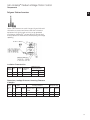
The preceding operating parameters have been determined
to produce an Iron Phosphate coating of a minimum of 150
milligrams per square foot to meet MIL Spec. TT-C-490.
Phase II — Painting by electro-static powder process
670-011 ANSI-61 Polyester Finish Paint (Light Gray)
Metal parts will enter a drying oven at 375-400° F and
remain for 20 minutes. The standard color finish is ANSI-61
light gray with a gloss of 60 plus or minus five and a thickness of 2.5 mils. This system will withstand a minimum of
1000 hours salt spray test.
Standard Commercial Tests and Inspections
General
The following summary description defines the standard
factory tests and inspections performed during manufacture
of Limitamp Control. All Limitamp equipment is tested and
inspected for conformance with NEMA ICS 3 part 2 and UL347.
Production tests and inspections encompass the verification
of physical configuration of assembly and workmanship, the
mechanical adjustments of parts and components, and the
sequencing and functional operations of the control systems.
These tests and inspections are performed on manufactured
products to verify conformance of the equipment to a previously
qualified design. The tests do not include type testing or other
destructive tests on equipment to be shipped to a customer.
Any additional factory tests beyond those listed in the following
paragraphs must be referred to the factory to verify availability of test facilities and qualified manpower. Additional testing
beyond the scope of the following standard commercial
tests will affect normal shipment schedules.
Production Tests
The following list of inspection activities shall be performed
to assure proper and correct materials, workmanship and for
any damage conditions in accordance with the manufacturing
documentation and drawings:
• Components, parts and material
• Physical condition of components, parts, wire insulation
• Location and orientation of components and parts
• Finish - plating - painting
• Wire/cable type, size, insulating and clamping support
• Wire terminations, insulation removal and crimping
of terminals
• Tightness of electrical connections and torque of bus
bar bolts
• Wire markers and terminal markers (where specified)
• Labeling of components, parts, etc.
• Tightness torque of assembly bolts and hardware
• Welds (spot only)
• Mechanical clearance
• Electrical clearance (potential hazards)
H2
Mechanical Operation Tests
Mechanical operating tests shall be performed to ensure
proper functioning of operating mechanisms and interlocks.
The operation of shutters, mechanical interlocks, circuitbreaker-door interlocks, operating handles, trip mechanisms,
solenoid armature travels, contact wipes, electro-mechanical
interlocks, physical clearances for mechanical and electrical
isolation including any additional mechanically related
operating functions shall be verified.
Continuity Tests — Control Wiring And Power Cables
The correctness of the individual circuit wiring contained in
each assembly and the assembly wiring interfaces shall be
verified as in accordance with the connection diagram,
wiring table, or elementary drawing. The continuity of each
circuit shall be checked.
Operations Test
All equipment shall be subjected to an operational test. The
test shall verify the functional operation of the control and
power circuits and related components, devices and subassembly-modules under simulated operating conditions
(excluding loading of the power circuits).
a. Devices
All devices, including subassembly-modules, shall be operated,
set and checked for their functional characteristics in accordance with the instructions for each and any additional
characteristic peculiar to the device:
• Pick-up
• Drop-out
• Contact wipe
• Amperes
• In-rush current
• Time-delay
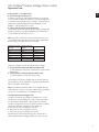
Contactors must pick-up and hold-in at or below the following
percentage of rated coil voltage:
Device Type
DC
AC
DC
DC
Voltage Source
DC
AC
AC with rectifier
AC with rectifier
Pick-up (Percentage)
65
851
70 with holding resistor
70 with holding and pick-up resistor
1 If a CPT is used, apply 90% voltage to transformer primary.
b. Sequence and timing circuits
Assemblies and systems involving sequential operation of
devices and time delays shall be tested to assure that the
devices in the sequence function properly and in the order
intended.
c. Polarity — phase-sensitive circuits
The polarity of direct-current circuits and phase connections
of alternating-current circuits shall be verified by application
of power and measurement of the relative polarities and
phase sequence.
d. Grounding
The grounding circuits and buses shall be verified.