1
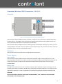
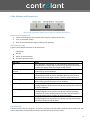
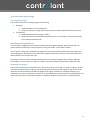
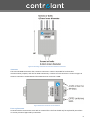
Controlant Transceivers
User‘s Guide
Type
CO 01.01
Description
Wireless transceiver with GPRS
Version 1.1
2/9/2011
Controlant ehf | Grensasvegur 7, 108 Reykjavik, Iceland |+354-517-0630 | www.controlant.com
©Controlant ehf. All Rights Reserved.
Controlant provides this document “as is,” without warranty of any kind, either expressed or implied,
including, but not limited to, the implied warranties of fitness or merchantability for a particular purpose.
Controlant may make improvements and/or changes in this manual or in the product(s) and/or the
program(s) described in this manual at any time.
This product could include technical inaccuracies or typographical errors. Changes are periodically made to
the information herein; these changes may be incorporated in new editions of the publication.
2
Contents
General Information ........................................................................................................................................... 4
About this guide ............................................................................................................................................. 4
Scope .............................................................................................................................................................. 4
Warranty exception ........................................................................................................................................ 4
Additional reference material ........................................................................................................................ 4
Questions and technical support.................................................................................................................... 4
Controlant Wireless GPRS Transceiver - CO 01.01 ............................................................................................. 5
Overview......................................................................................................................................................... 5
Enclosure ........................................................................................................................................................ 5
Power options ................................................................................................................................................ 5
Power supply .............................................................................................................................................. 5
Battery pack ............................................................................................................................................... 5
LEDs, Buttons and Connectors ....................................................................................................................... 6
Connection and power-on ......................................................................................................................... 6
LED indicator light ...................................................................................................................................... 6
On/Off Switch ............................................................................................................................................. 6
Power connector ........................................................................................................................................ 7
Specifications and ratings ............................................................................................................................... 8
Environmental range .................................................................................................................................. 8
Handling and installation................................................................................................................................ 8
Mounting orientation ................................................................................................................................. 8
Antennas .................................................................................................................................................... 9
Fuse replacement ....................................................................................................................................... 9
Wireless Connectivity ...................................................................................................................................10
GPRS connectivity..................................................................................................................................... 10
3
General Information
About this guide
This guide describes the features and functions of a Controlant wireless transceiver product, CO 01.01, with
GPRS connectivity. The guide includes connection and setup information, configuration, data retrieval, LEDs
and buttons.
Scope
This guide covers Controlant wireless transceiver CO 01.01. Please contact Controlant at
[email protected] for questions regarding compatibility between hardware and software versions.
Warranty exception
Opening the enclosure of the CO 01.01, unless supervised or carried out by service personnel approved by
Controlant, voids all warranty against equipment malfunction.
Controlant’s CO 01.01 wireless transceiver products ships with batteries included. Lithium batteries must
be replaced by Controlant or service personnel approved by Controlant. No warranty is on the behavior of
Controlant’s equipment in case of wrong battery installation by non-qualified personnel or in case of usage
of batteries which Controlant does not approve of.
Additional reference material
Additional information about features and functions of Controlant transceiver products can be found at
www.controlant.com
Questions and technical support
For technical assistance with your product, contact Controlant Technical Support at +354-517-0630 or
[email protected]
4
Controlant Wireless GPRS Transceiver - CO 01.01
Overview
Figure 1: Illustration of the C0 01.01 wireless GPRS transceiver
The Controlant wireless GPRS transceiver, CO 01.01, provides on-line connectivity to multiple Controlant
wireless sensors. The purpose of the transceiver is to gather measurements from multiple sensors in its
vicinity and transfer the data to a centralized on-line database.
The Controlant wireless GPRS transceiver is able to generate and broadcast warnings via e-mail or in a text
message (SMS) if measured values are outside of a user defined range. The transceiver has a built-in lithium
Ion battery which is used as a backup power source.
Enclosure
The CO 01.01 transceiver is offered in a standard aluminum enclosure.
Power options
Power supply
The Controlant wireless GPRS transceiver should be DC powered using an external power source. The
operating range of the device is 7-13V DC and the external power supply should be limited to maximum DC
output current above 1A and below 2A. Detailed information about the DC power connector plug is
provided below.
Battery pack
Each CO 01.01 transceiver has a built in lithium Ion battery which will keep the system running in case of
external power failure. The battery should only be replaced by Controlant employees or trained personnel
approved by Controlant. In case of replacement, only batteries approved by Controlant should be used.
CAUTION!
RISK OF EXPLOSION IF BATTERY IS REPLACED BY AN INCORRECT TYPE. DISPOSE OF USED BATTERIES
ACCORDING TO THE INSTRUCTIONS.
5
LEDs, Buttons and Connectors
Figure 2: LED, On/Off switch and DC power connector for the CO 01.01 transceiver.
Connection and power-on
1. Connect the DC plug of the external power supply to the DC power inlet.
2. Turn on the power switch.
3. Wait for the LED indicator light to indicate full operation.
LED indicator light
A green LED indicates the status of the transceiver.
Indications:
On/Off
Status of external power
On-line connection status
LED status
Off
Off, blinking every 0.5
seconds
Off, blinking every 2 seconds
Off, blinking every 4 seconds
On, blinking every 0.5 seconds
On, blinking every 2 seconds
On, blinking every 5 seconds
Status
The transceiver is turned off, or is not operating. (Note that if the
internal battery is empty the transceiver may take up to 20 minutes
to reach the charge necessary to operate the system)
Operating on battery. The local network is up and running. No
connection to central database.
Operating on battery. The local network is up and running.
Initializing connection to central database.(Note that more than 4
minutes in this mode might indicate a failure in GPRS connection)
Operating on battery. The local network is up and running.
Data is being transferred to the central database.
Charging mode. The transceiver is connected to a power source and
is being charged. The local network is up and running. No connection
to central database.
Charging mode. The transceiver is connected to a power source and
is being charged. The local network is up and running. Initializing
connection to central database.(Note that more than 4 minutes in
this mode might indicate a failure in GPRS connection)
Charging mode. The transceiver is connected to a power source and
is being charged. The local network is up and running. Data is being
transferred to the central database.
On/Off Switch
The power switch has two purposes, to set the transceiver into hibernation mode and to do a full reset. The
power switch does not physically disconnect the device from the power source.
6
The transceiver is therefore able to send an indication of the current power state before going into
hibernation, making operators able to identify whether or not the device has been turned off or if there has
been a failure in the system.
On/Off Switch
On
Off
Toggled Off for less than 2 seconds
Toggled Off for more than 2 seconds and less
than 10 seconds
Toggled Off for more than 10 seconds
Behavior
Full function of the transceiver.
Hibernation mode. All modules go to
hibernation mode and wait until the switch is
turned on again.
Has no effect on the transceiver.
Resets all sub-systems within the transceiver.
Powers up from reset normally.
If toggled Off for more than 10 seconds the
transceiver goes into hibernation mode. The
transceiver remains in that state until the
On/Off switch is set to On again. After that the
transceiver powers on normally.
Power connector
The power connector dimensions are 2.5 x 5.5 x 14 mm as shown in Figure 3 and the polarity is shown in
Figure 4Figure 3: Mechanical drawings of the DC power plug on the CO 01.01.
Figure 3: Mechanical drawings of the DC power plug on the CO 01.01
Figure 4: Polarity of the DC power connector on the CO 01.01 wireless transceiver.
7
Specifications and ratings
Environmental range
The wireless transceiver’s working range is the following
1. Humidity
a. 0-99% humidity for normal operation.
b. Long term exposure to high levels of humidity may cause unexpected behavior in device.
2. Temperature
a. Recommended operating range is 0-40°C
b. Absolute minimum and maximum temperatures are -20°C and 60°C. Functionality may be
lost at extreme temperatures
Handling and installation
The transceivers rugged enclosure ensures a good protection against damage. The enclosure does not
protect external components such as antennas, wiring and cables, on/off switch and LED.
The enclosure is designed to withstand spraying water from vertical downward direction (up to 60° from
vertical alignment). Orientation of the transceiver should therefore be vertical for maximum protection as
demonstrated in the image to the right.
Cleaning of transceivers should be done with neutral soap to prevent rubber sealing, buttons and LEDs
from failing. In case of a need to sanitize or sterilize, use alcohol based compounds and wipe with cloth.
Mounting orientation
The wireless transceiver can be mounted to a surface by using screws or bolts as shown in Figure 5. Screws
and bolts must be chosen according to the mounting surface. The transceiver weighs 370 g. Care must be
taken that screws and bolts can handle the weight for the given surface type. Improper mounting and
installation can cause the transceiver to fall from its intended position and cause harm to nearby people. To
lower risk of harm due to improper installation, installation should be carried out by a qualified person.
8
Figure 5: Mounting orientation of Controlant wireless transceivers
Antennas
The CO 01.01 GPRS transceiver has 3 antenna connectors. Two are intended for local wireless
communication purposes, and one for GPRS connectivity. Location of each connector is shown in Figure 6.
Antenna connectors are RP-SMA and the GPRS antenna connector is SMA.
Figure 6: Antenna connectors on the CO 01.01
Fuse replacement
CO 01.01 wireless transceivers come with an internal fuse. The fuse should only be replaced by Controlant
or service personnel approved by Controlant.
9
Wireless Connectivity
Controlant wireless devices have up to 400m range in open air. The communication frequency channels are
around 868MHz.
The range in open air depends on various factors, including:
1. Mounting and antenna orientation.
2. Proper assembly and selection of antennas.
3. Disturbance on communication frequencies caused by electronic devices, both low and high
current.
4. Disturbance on communication frequencies caused by other wireless devices.
Wireless range is significantly affected by occlusion by objects. The indoor range of Controlant devices
depends on various factors, including:
1.
2.
3.
4.
Building materials in walls and ceilings.
Metal objects occluding the path of the signal.
Proper assembly and selection of antennas.
Disturbance on communication frequencies caused by electronic devices, both low and high
current.
5. Disturbance on communication frequencies caused by other wireless devices.
GPRS connectivity
The GPRS connectivity depends on the network coverage of the network service provider in that area. If the
LED on the transceiver indicates that no signal can be found – try to move the transceiver to an open
location (window, open air etc.) or contact the network service provider for information about network
coverage in your area.
10