1
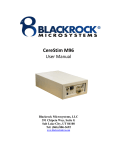
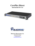
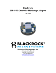
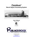
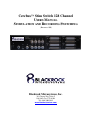
Cerebus™ Stim Switch 128 Channel
USERS MANUAL
STIMULATION AND RECORDING SWITCHING
(REVISION 1.00)
Blackrock Microsystems, Inc.
391 Chipeta Way, Suite G
Salt Lake City, UT 84108
Tel: (866) 806-3692
www.blackrockmicro.com
CerebusTM Stim Switch 128-Channel Users Manual
© Copyright 2010 Blackrock Micosystems, Inc. All rights reserved. Copying or other reproduction of this document is
prohibited without prior written consent of Blackrock Microsystems, Inc.
CerebusTM is a trademark of Blackrock Microsystems, Inc.
Rev. 1.00
LB-0265
Page i
CerebusTM Stim Switch Users Manual
Table of Contents
1 System Overview ............................................................................................................................1
1.1 Packing List .............................................................................................................................................................. 1
2 Hardware.........................................................................................................................................2
2.1 Stim Switch Control Module ...................................................................................................................................... 2
2.2 Stim Switch Headstage Module ................................................................................................................................... 4
2.3 Computer Setup ........................................................................................................................................................... 5
2.4 Hardware Setup ............................................................................................................................................................ 5
2.5 External Gating of the Stim Switch using the Enable In input..................................................................................... 5
3 StimComm Software ......................................................................................................................7
4 System Specifications ...................................................................................................................10
5 Troubleshooting ............................................................................................................................11
6 Warranty .......................................................................................................................................13
6.1 Return Merchandise Authorization ............................................................................................................................ 13
List of Figures
Figure 1-1: Application Overview ....................................................................................................1
Figure 2-2: Stim Switch Control Module Front Panel ...................................................................2
Figure 2-3: DB-37 Stimulator Connection Layout .........................................................................3
Figure 2-4: Power Supply Switch .....................................................................................................3
Figure 2-5: Stim Switch Headstage Module ...................................................................................4
Figure 2-6: Switch Schematic. Rstim = 500 MΩ and Relec = 1kΩ ..............................................4
Figure 2-7: Stim Switch Computer Interface ................................................................................5
Figure 2-8: Fast Settle modified Front End Amplifier...................................................................5
Figure 3-9: StimComm Main Window ............................................................................................7
List of Tables
Table 2-1: Behavior of the Enable In Port ......................................................................................3
Table 2-2: Headstage Module switching states ..............................................................................4
Rev. 1.00
LB-0265
Page ii
CerebusTM Stim Switch Users Manual
1
System Overview
The Cerebus Stim Switch provides unprecedented electrode-switching control for neural
stimulation applications by enabling high-quality neural recordings immediately after stimulation.
The Stim Switch is designed as an add-on module for the Cerebus data acquisition system. It
allows researchers to programmatically switch individual electrodes between a stimulation source
and a Cerebus front-end amplifier. Each Stim Switch can switch up to 128 electrodes (32 in each
bank). The figure below shows an application overview of how a Cerebus Stim Switch fits into a
complete stimulation system.
Figure 1-1: Application Overview
1.1
Rev. 1.00
LB-0265
Packing List
1
Cerebus Stim Switch Control Module
1
Stim Switch Control Module Accessory Kit
1
Power Cord
2
Rack Mounting Ears
4
Screws
4
Rubber Mounting Feet
1
1
Cerebus Stim Switch Software CD-ROM
Cerebus Stim Switch Manual
1
USB A-B Cable
1
Stim Switch Headstage Kit
1
Headstage Module
1
Headstage Module Cable (50 Conductors, 3ft long)
Page 1
CerebusTM Stim Switch Users Manual
2
Hardware
2.1
Stim Switch Control Module
The Stim Switch Control Module interfaces the Headstage Module with the digital control
computer and analog stimulation source. Stim Switch configuration is accomplished using the
StimComm program described in Section 3.
Figure 2-2: Stim Switch Control Module Front Panel
Power Switch (1): Use the power switch to turn on the Stim Switch Control Module. An LED just
above the power switch will illuminate the color blue to indicate that the unit has power.
Emergency Stop (2): The emergency stop jack is used to attach an emergency stop switch (not
included) if emergency stop capabilities are required for your application. When activated, the
emergency stop controller will set all of the headstage channels to blanking mode, clear the mode
registers, and notify the PC of the emergency condition. The Stim Switch Control Module is
designed for use with Normally Open (NO) Emergency Stop Switches.
USB CMD Port (3): Control of the Stim Switch is accomplished through commands sent via a
USB A-B cable connected between the USB Port on the Stim Switch and the USB Port of the PC.
A green LED above the port illuminates during activity on the port. If an error occurs, the LED will
flash red.
FS Out (4): The Fast Settle Out BNC connector is used to drive the fast settling input of a Front
End Amplifier. The fast settling input reduces the Front End Amplifier’s time to measurement
after switching events for action potentials, which enables switching times as fast as 5 ms. This
is accomplished by adding an additional pole to the frequency response of the amplifier. Without
the fast settle feature, there is a delay of 3-5 seconds after switching back to recording mode
before signals can be recorded.
Whenever any of the Status Out lines are high, the FS Out connection is also high which is
indicated on the Stim Switch by the illumination of a green LED above the connector.
Enable In (5): Four 3.3 V Enable In (labeled 1, 2, 3, and 4) BNC connectors can be used to
enable/disable single or multiple banks of the stimulation connections simultaneously. The green
LED above each Enable In connector indicates the current status of the Enable In input. The
connection is normally held high (3.3 V). The Stim Switch is disabled when the connection is
connected to ground (0 V). The exact details are specified in the table below. This connection is
required for applications which require external control of switching. Each Enable In port is
designed for use at 3.3 V, but they can also be used with inputs rated between 2.5 V and 5.0 V.
Rev. 1.00
LB-0265
Page 2
CerebusTM Stim Switch Users Manual
Table 2-1: Behavior of the Enable In Port
Voltage
Behavior
3.3 V
Normal Operation. All channels behave as set
by the StimComm software.
0V
All channels set to recording mode when the
StimComm software is set to either recording
or stimulation mode. When in blanking mode,
the Enable In switch has no effect.
Status Out (6): Four yellow LEDs above the Status Out BNC connectors (labeled 1, 2, 3, and 4)
indicate whether stimulation mode has been enabled for the corresponding bank of stimulator
connections. When a bank of stimulator connections is disabled, the LED above the associated
Status Out connector is turned off.
Individual Front End Amplifiers can be connected to any of the four Status Out BNC connectors
for independent control of fast settling.
Headstage Cable Connectors (7): Each bank on the front panel of the Stim Switch contains a
connector for a 50 conductor Headstage Module Cable. These cables provide the interface
between the Stim Switch and the Headstage Module (see section 2.2 below). The power switch
on the Stim Switch should always be turned off when connecting or disconnecting the Headstage
Module Cable.
The LED next to each connector indicates the connection status of the corresponding Headstage
Module. When the Headstage Module is connected appropriately, the LED will light up green.
During stimulation or blanking modes, the LED turns yellow. If an error occurs in the connection,
the LED will turn red.
Stimulator Connections (8): Stimulation inputs can be connected directly into the DB-37
connectors for each bank of stimulation channels. The ground of the stimulation inputs and the
Headstage Module are isolated from earth ground. The area of the Stim Switch which is isolated
is denoted by the dotted line on the front panel of the Stim Switch.
When a stimulation channel is turned on in the StimComm software, it is connected directly to the
corresponding electrode output channel on the Headstage unit. The layout of the DB-37
stimulator inputs is shown in the figure below.
Figure 2-3: DB-37 Stimulator Connection Layout
Subject Ground (9): The subject ground should be connected to the
Subject Ground connector. Internally the Stim Switch provides a minimum
isolation of 500 VACrms between the subject ground and chassis ground.
Power Connector: The power connector on the back of the Stim Switch is
capable of 100-220 V AC input. Please select the appropriate voltage
using the wheel selector as pictured in the figure to the right before
Rev. 1.00
LB-0265
Figure 2-4:
Power Supply
Switch
Page 3
CerebusTM Stim Switch Users Manual
plugging in the Stim Switch for the first time. There are also two fuses in the power supply that
may need to be replaced if the Power Supply is connected to the wrong voltage.
2.2
Stim Switch Headstage Module
The Headstage Module provides connection
between the Cerebus Front End Amplifier, the
electrodes, and the Stim Switch. LEDs on the
module indicate power (1), blanking enabled (2), and
stimulation enabled (3).
The Headstage Module is connected to the Stim
Switch with the Headstage Module Cable. The
power switch on the Stim Switch should always
be turned off prior to connecting or
disconnecting the headstage module cable.
The Headstage Module is built around connectors
from Samtec (www.samtec.com) and is designed to
mate with the ICS family of array holders from
Blackrock Microsystems. Please refer to the
Cerebus User Manual or contact a Blackrock sales
representative for more information on the
different connectors available for use with the Stim
Switch headstage module.
Each Channel on the Headstage Module is rated for
a maximum voltage of ±15 V with respect and
ground and can source or sink a maximum of 30 mA
of current. The diagram on the right illustrates the
internal connections of a single channel in the
Headstage Module. The Amplifier Blanking Switch is
closed during Read mode and open during
Stimulation and Blanking modes. The Stimulator
switch is only closed when the Headstage Module is
configured in Stimulation mode and the channel has
been selected for Stimulation using the StimComm
software. The table below defines the state of each
switch for a single channel for any given set of inputs.
Figure 2-5 Stim Switch Headstage Module
Figure 2-6: Switch Schematic.
Rstim = 500 MΩ and Relec = 1kΩ
Table 2-2: Headstage Module switching states
Channel State
Amplifier Blanking Switch
Stimulator Switch
Read
Closed
Open
Blanking
Open
Open
Stimulation (channel not set for stimulation)
Open
Open
Stimulation (channel set for stimulation)
Open
Closed
Rev. 1.00
LB-0265
Page 4
CerebusTM Stim Switch Users Manual
2.3
Computer Setup
The Stim Switch connects to a USB port on
the computer through a standard USB A-B
cable. The StimSwitch uses an internal
USB to serial converter and will appear as
a COM port on your computer. Be sure
that the COM assigned by your computer
to the Stim Switch matches the COM port
settings in the StimComm Software (See
Figure 2-7 Stim Switch Computer Interface
Menu Options in section 3 for instructions on changing COM port settings).
2.4
Hardware Setup
1. Unpack all components of the Cerebus Stim Switch.
2. Connect the USB port on the Stim Switch to a USB port on the computer with the USB A-B
cable that is included in the packaging.
3. Verify that the voltage switch on the back of the Stim Switch Control Module matches the line
voltage for your region.
4. Plug in the Stim Switch Control Module using the included power cable. Do not turn the
system on yet.
5. Plug in the Emergency Off Switch if required for your application.
6. Plug one end of the Headstage Cable into one of the four banks
of Headstage connectors on the Stim Switch Control Module.
Plug the other end into the Headstage Module. Be careful, the
connections are keyed, but it is possible to partially plug the
cable in backwards.
7. If you have a Fast Settle modified Front End Amplifier, connect
the Fast Settle BNC Cable from the modified Front End Amplifier
to the FS Out BNC connector on the Stim Switch Control
Figure 2-8 Fast Settle
Module. If you do not have a Fast Settle modified Front End
modified Front End
Amplifier, you can continue without making this connection, but
Amplifier
you will be unable to record for approximately 3-5 s after
switching between stimulation and recording modes. Front End Amplifiers can also be
connected to any of the Status Out BNC connectors that correspond to Banks A-D for
independent fast settling.
8. Power up the system to verify functionality.
2.5
External Gating of the Stim Switch using the Enable In input
1. Connect the Stim Switch as described in the previous section.
2. Connect stimulation sources to the desired banks of stimulation channels on the Stim Switch
Control Module.
Rev. 1.00
LB-0265
Page 5
CerebusTM Stim Switch Users Manual
3. Using the StimComm software, select the desired channels for stimulation by checking the
boxes next to the electrode numbers and pressing the ‘Set Electrodes’ button. Electrode
numbers can be selected independently for each bank of stimulation channels by selecting
the tabs at the top of the window.
4. Connect a control device to the Enable In inputs using a BNC cable. The control devices can
be any device that toggles between 0 V and 3.3 V (2.5 V and 5 V devices can also be safely
used). Here are a couple examples of devices that could be used:
•
An external trigger output on a stimulation source.
•
A function generator set to generate a 3.3 V square wave.
•
A toggle switch that is connected to ground (0 V) when closed.
5. Stimulation is enabled by pressing the ‘Set Stim’ button in the StimComm program.
6. The Stim Switch will now set the Headstage to recording mode whenever the Enable In
voltage is low (0 V) and will set the Headstage to stimulation mode whenever the Enable In
voltage is high (≥ 2.5 V)
Rev. 1.00
LB-0265
Page 6
CerebusTM Stim Switch Users Manual
3
StimComm Software
The StimComm software runs under Windows XP Professional, Windows Vista, or Windows 7.
The StimComm software can be installed from the supplied CD by running the setup.exe
program. Once the program has been installed, the StimComm software can be started by
double clicking the StimComm desktop shortcut that was created by the installation program, or
by launching the StimComm.exe program in the installation directory, C:\Program
Files\Blackrock Microsystems\StimComm. The main features of the StimComm
program are described below, following the screenshot of the program’s main window.
NOTE: Only open the StimComm Software after plugging in the headstage module and turning
on the power supply for the Stim Switch. Otherwise, the software will not recognize the headstage
module.
Figure 3-9: StimComm Main Window
Electrode Selection Panel (1): Channels intended for stimulation can be selected by clicking the
box to the left of the appropriate channel name so that a check appears in the box. Electrodes
can be independently selected for Banks A-D by selecting the Electrode tabs at the top of the
window. All 32 electrodes in the bank can be selected or deselected using the ‘Check All’ or
‘Uncheck All’ buttons at the bottom of the panel. Changes are not updated to the Stim Switch
until the Set Electrodes button is pressed.
Stim Control Panel (2): Stimulation and Headstage Module settings can be altered using the
options that are available in the Stim Control panel:
Disabled: In this mode, all stimulation channels for the selected bank are disconnected.
Rev. 1.00
LB-0265
Page 7
CerebusTM Stim Switch Users Manual
Control On: This mode allows for continuous stimulation of the selected bank. The
Control On feature can be used as a method for manually controlling switching between
stimulating and recording. Turn stimulation on by pressing the ‘Set Stim’ button. Click the
‘Set Record’ button to switch to recording mode.
Enable A-D: This feature assigns single or multiple Enable In connectors to the stimulation
inputs on the selected bank. Enable In connections enable/disable the stimulation inputs
and initiate switching between stimulation and recording modes. Turn stimulation on by
pressing the ‘Set Stim’ button.
Timed: This feature allows for periodic switching between stimulation and recording
modes. This box must be selected to use the Timer Control panel. Turn stimulation on by
pressing the ‘Set Stim’ button. Note: Make sure no other options in the Stim Control panel
are selected in order to use this feature.
Blanking: This box must be selected to enable automatic switching between stimulation
and blanking modes. If this box is not visible and you would like to activate it, see Section 5
below for instructions on adding registries to StimComm.
Selecting the Blanking and Enable A-D options, results in switching between stimulating
and blanking modes.
Set Record: In this mode, all selected electrodes in the bank are set to pass through read
mode and all stimulation channels are disconnected.
Set Blank: All 32 channels within the selected bank are blanked and all of the stimulation
switches are opened. While the channels are blanked, the electrode connectors on the
heastage are not connected to either the stimulation source or the recording amplifier.
Set Stim: The channels specified for stimulation in the Electrode Selection area are set to
stimulation mode. All channels not selected for stimulation are blanked while in stimulation
mode.
Timer Control Panel (3): Periodic switching between Stimulation and Recording modes can be
setup using the Timer Control feature. For this feature to be enabled, the ‘Timed’ box in the Stim
Control panel must be selected.
Period: Enter the period setting in seconds for the selected bank (required).
Duty Cycle: Enter the duty cycle as a decimal value in seconds (required).
Offset: This feature allows you to provide an offset value in seconds that will start the
stimulation at the specified time following the start of the period.
Cycle Count: Periodic switching can be set to stop after a specific number of cycles. If the
number of cycles is set to ‘0,’ switching will continue until the ‘Stop Timer’ button is pressed.
Set Timer Values: This button must be pressed following any changes that are made to
the values in the Timer Control panel in order for subsequent timing cycles to recognize the
new values.
Start/Stop Timer Buttons (4): Use the ‘Start Timer’ button to begin periodic switching between
Stimulation and Recording modes. When the ‘Start Timer’ button is pressed, the timing cycle will
begin for each active bank simultaneously. Upon completion, a message will appear in the
Console Window indicating when the timing cycle for each bank has ended. The ‘Stop Timer’
Rev. 1.00
LB-0265
Page 8
CerebusTM Stim Switch Users Manual
button must be pressed after each timing cycle in order to begin timing again. This button can
also be used to manually stop the timing cycle.
Active Timer Panel (5): This panel displays the banks that are actively undergoing periodic
switching after the ‘Start Timer’ button is pressed.
Menu Options (6):
Saving and Restoring Settings: The StimComm program allows you to save current
settings to a file and restore those settings later. Settings can be saved by clicking the File
menu and selecting the Save Settings option. Previously saved settings can be restored by
selecting the Load Settings option in the File menu.
Assigning COM ports: Selecting Settings from the Options menu allows you to assign
COM ports on your machine in the StimComm program. You can determine which COM
ports are available on your system by right clicking on “My Computer” in the Start Menu and
selecting Manage -> Device Manager. In the device manager pane you should see a list of
com ports under the Port (COM & LPT) heading in the device manager. By default, the
StimComm program is set to use COM4. If you need to change the port assignment, you
can do that in the settings window. After changing the port settings, you will need to quit
and restart the StimComm program for the settings to take effect.
Rev. 1.00
LB-0265
Page 9
CerebusTM Stim Switch Users Manual
4
System Specifications
CEREBUS STIM SWITCH
Stimulation Inputs
4 DB-37 front panel connectors
1.3 kΩ impedance between input and output when stimulation
mode is enabled.
> 10 MΩ input impedance when stimulation mode is disabled
Recording Outputs
36 Channel Samtec Connector with 32 output channels plus
reference and ground pins.
1.1 kΩ impedance between input and output when read mode is
enabled.
> 10 MΩ output impedance when read mode is disabled.
Minimum Switching Time
< 1 µs when using the Enable In input to switch between modes
10ms when using StimComm to switch between modes
Maximum Time after switching
< 5 ms using Fast Settle modified Cerebus Front End Amplifier
before action potentials are valid
< 4 s using unmodified Cerebus Front End Amplifier
Maximum Stimulation Input
Current
30 mA on any one channel
Maximum Stimulation Input
Voltage Range
±15 V between any input and ground on any one channel
Enable In Input Voltage Range
-0.1 V to +5.0 V
Bank to Bank Synchronization
<1 µs skew.
PC Hardware Interface
USB A-B cable
StimComm PC Software
Compatibility
Windows 2000 Pro, Windows XP Pro, Windows 7, or Windows
Vista
Internal Power Supply
Standard 3-pin PC power connector accepting 110-240 VAC, 5060 Hz
Emergency Off Switch
¼” Mono Phone Plug
Normally Open Switch with < 1 kΩ on resistance recommended.
Rev. 1.00
LB-0265
Page 10
CerebusTM Stim Switch Users Manual
5
Troubleshooting
I live in a country with 220 V power, but the back of the Stim Comm Control
Module says 110 V.
You can change the power supply voltage rating by flipping open the panel above the plug on the
back of the module and rotating the wheel so that it says 220 V.
The Blanking Box is not visible when I open StimComm.
1.
Click on the Startup Menu.
2.
In the Search Box, type regedit. Click yes when asked if you want to allow this program
to make changes to your computer.
3.
Locate and select the StimComm Software folder.
4.
Right click in the empty window space.
5.
Select New->DWORD (32-bit) value.
6.
Enter the name of the registry that you would like to add (case sensitive)
•
Type ‘Blanking Mode’ to turn on the Blanking box
7.
Right click on the newly added registry
8.
Select Modify and change the ‘0’ to ‘1’. Leave the Base set to Hexadecimal. If you want
to turn the registry off again, change the ‘1’ back to a ‘0.’
9.
Select Ok.
My Stim Switch Control Module will not turn on.
Check the fuses behind the panel above the power supply plug on the back of the unit and
replace them if necessary. Ensure that the rotary voltage selector is set correctly for your line
voltage (either 110 V or 220 V). If that doesn’t work, please contact Blackrock Microsystems for
additional troubleshooting or to initiate an RMA.
I don’t seem to be able to send any commands to the Stim Switch Control
Module. Nothing is echoed in the status area of StimComm.
Rev. 1.00
LB-0265
1.
Make sure that all cables are plugged in correctly. Reread all of the descriptions in
Section 2.1 to make sure that all connections are correct.
2.
Check that the Headstage Module is recognized. The PWR LED on the Headstage
should be lit and the Headstage Module LED for each bank that is in use on the Stim
Page 11
CerebusTM Stim Switch Users Manual
Switch Control Module should be green. If it is red try disconnecting the Stim Switch
cable and ensuring that both ends are plugged into the Headstage Module and the
Control Module correctly. They are keyed and should only be inserted one way.
Rev. 1.00
LB-0265
3.
Watch the light above the USB port on the Stim Switch when you send a command. It
should flash green briefly when the command is sent. If the light doesn't light up or is
red, try disconnecting and then reconnecting the USB A-B cable making sure that both
ends are fully securely plugged into the ports.
4.
Check which COM ports are available on your computer. Right click on “My Computer” in
the Start menu in Windows and select Manage->Device Manager. Find the Ports (COM
& LPT) category and open the subtree to find which ports are available on your computer.
Try switching the USB A-B cable to a different port and changing the port assignments in
the StimComm settings menu. Reinstall the StimSwitch USB drivers from the CD.
5.
If the above steps fail, you may have a defective unit. Please contact Blackrock
Microsystems for additional technical support or to initiate an RMA.
Page 12
CerebusTM Stim Switch Users Manual
6
Warranty
Blackrock Microsystems, Inc. warrants that its products are free from defects in materials and
manufacturing for a period of one year from the date of shipment. Blackrock will, at its option,
repair or replace any product that does not comply with this warranty. This warranty is voided by:
1. Any modification or attempted modification to the product done by anyone other than an
authorized Blackrock employee
2. Any abuse, negligent handling or misapplication of the product.
This constitutes the sole warranty made by Blackrock, Inc. There are no other warranties,
expressed or implied, which extend beyond those described herein or to anyone other than the
original purchaser, including the implied warranties of merchantability and fitness for a particular
purpose. In no event shall Blackrock Microsystems, Inc. be liable for any incidental or
consequential damages, or for the infringement of any patent rights or third party rights due to the
use of its products. The equipment detailed in this user manual is intended for research with
animal subjects only and is not suitable for experimentation with human subjects.
6.1
Return Merchandise Authorization
In the unlikely event that your Cerebus system needs to be returned to Blackrock for repair or
maintenance, do not send any equipment back without a Return Merchandise Authorization
Number. An RMA number will be issued to you by a Blackrock representative. If you need to
obtain an RMA number, you may contact a product support representative at (801) 582-5533 or
toll free at (866) 806-3692.
Once an RMA number has been issued, it is important to safely pack the returned item for
shipping back to Blackrock. It is preferred that you save the original boxes and packing materials
that your Cerebus system arrived in for return shipment. Please address the package as follows:
Blackrock Microsystems, Inc.
ATTN: RMA#
391 Chipeta Way, Suite G
Salt Lake City, UT 84108 USA
Tel: (801) 582-5533
Rev. 1.00
LB-0265
Page 13