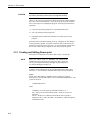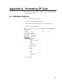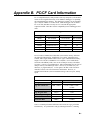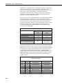
1
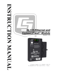
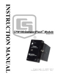
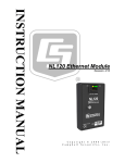
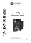
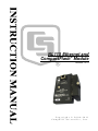
NL115 Ethernet and
CompactFlash® Module
Revision: 12/11
C o p y r i g h t © 2 0 0 6 - 2 0 1 1
C a m p b e l l S c i e n t i f i c , I n c .
Warranty
“PRODUCTS MANUFACTURED BY CAMPBELL SCIENTIFIC, INC. are
warranted by Campbell Scientific, Inc. (“Campbell”) to be free from defects in
materials and workmanship under normal use and service for twelve (12)
months from date of shipment unless otherwise specified in the corresponding
Campbell pricelist or product manual. Products not manufactured, but that are
re-sold by Campbell, are warranted only to the limits extended by the original
manufacturer. Batteries, fine-wire thermocouples, desiccant, and other
consumables have no warranty. Campbell's obligation under this warranty is
limited to repairing or replacing (at Campbell's option) defective products,
which shall be the sole and exclusive remedy under this warranty. The
customer shall assume all costs of removing, reinstalling, and shipping
defective products to Campbell. Campbell will return such products by surface
carrier prepaid within the continental United States of America. To all other
locations, Campbell will return such products best way CIP (Port of Entry)
INCOTERM® 2010, prepaid. This warranty shall not apply to any products
which have been subjected to modification, misuse, neglect, improper service,
accidents of nature, or shipping damage. This warranty is in lieu of all other
warranties, expressed or implied. The warranty for installation services
performed by Campbell such as programming to customer specifications,
electrical connections to products manufactured by Campbell, and product
specific training, is part of Campbell’s product warranty. CAMPBELL
EXPRESSLY DISCLAIMS AND EXCLUDES ANY IMPLIED
WARRANTIES OF MERCHANTABILITY OR FITNESS FOR A
PARTICULAR PURPOSE. Campbell is not liable for any special, indirect,
incidental, and/or consequential damages.”
Assistance
Products may not be returned without prior authorization. The following
contact information is for US and international customers residing in countries
served by Campbell Scientific, Inc. directly. Affiliate companies handle
repairs for customers within their territories. Please visit
www.campbellsci.com to determine which Campbell Scientific company serves
your country.
To obtain a Returned Materials Authorization (RMA), contact CAMPBELL
SCIENTIFIC, INC., phone (435) 227-2342. After an applications engineer
determines the nature of the problem, an RMA number will be issued. Please
write this number clearly on the outside of the shipping container. Campbell
Scientific's shipping address is:
CAMPBELL SCIENTIFIC, INC.
RMA#_____
815 West 1800 North
Logan, Utah 84321-1784
For all returns, the customer must fill out a "Statement of Product Cleanliness
and Decontamination" form and comply with the requirements specified in it.
The form is available from our web site at www.campbellsci.com/repair. A
completed form must be either emailed to [email protected] or faxed to
(435) 227-9579. Campbell Scientific is unable to process any returns until we
receive this form. If the form is not received within three days of product
receipt or is incomplete, the product will be returned to the customer at the
customer's expense. Campbell Scientific reserves the right to refuse service on
products that were exposed to contaminants that may cause health or safety
concerns for our employees.
NL115 Table of Contents
PDF viewers: These page numbers refer to the printed version of this document. Use the
PDF reader bookmarks tab for links to specific sections.
1. NL115 Ethernet/Compact Flash Module Overview ...1
1.1 Specifications........................................................................................ 1-1
1.2 Physical Description ............................................................................. 1-2
1.3 Power .................................................................................................... 1-3
1.3.1 Primary Power ............................................................................ 1-3
1.3.2 Backup Power and Data Retention ............................................. 1-3
1.4 Function ................................................................................................ 1-3
1.5 Quick Start Procedure........................................................................... 1-3
1.5.1 Physical Set-up............................................................................ 1-3
1.5.2 Communicating via Ethernet ...................................................... 1-4
1.5.3 Programming the Datalogger to Send Data to the NL115 .......... 1-6
1.5.4 Data Retrieval ............................................................................. 1-7
2. TCP/IP Functionality.................................................2-1
2.1 Communicating over TCP/IP................................................................ 2-1
2.1.1 Data Call-back ............................................................................ 2-1
2.1.2 Datalogger-to-Datalogger Communication................................. 2-2
2.2 HTTP Web Server ................................................................................ 2-3
2.3 FTP ....................................................................................................... 2-4
2.3.1 FTP Server .................................................................................. 2-4
2.3.2 FTP Client................................................................................... 2-6
2.4 Telnet .................................................................................................... 2-7
2.5 Ping....................................................................................................... 2-7
2.6 Serial Server ......................................................................................... 2-7
2.6.1 Serial Input.................................................................................. 2-7
2.6.2 Serial Output ............................................................................... 2-8
2.7 TCP ModBus ........................................................................................ 2-8
2.8 DHCP ................................................................................................... 2-8
2.9 DNS ...................................................................................................... 2-9
3. File Formats ..............................................................3-1
3.1 Data Files.............................................................................................. 3-1
3.2 Program Files........................................................................................ 3-1
3.3 Power-up Files (powerup.ini) ............................................................... 3-1
3.3.1 Creating and Editing Powerup.ini............................................... 3-2
3.3.2 Applications ................................................................................ 3-3
3.3.3 Program Execution...................................................................... 3-4
3.3.4 Example Power-up.ini Files........................................................ 3-4
3.4 Camera Files ......................................................................................... 3-1
i
NL115 Table of Contents
4. Programming............................................................ 4-1
4.1 The CardOut Instruction ....................................................................... 4-1
4.2 Program Examples ................................................................................ 4-1
4.2.1 Ring Mode................................................................................... 4-1
4.2.2 Fill and Stop Mode...................................................................... 4-2
4.2.3 Mixed Modes .............................................................................. 4-2
4.3 Table Size and Mode ............................................................................ 4-4
5. Data Retrieval ........................................................... 5-1
5.1 Via a Communication Link................................................................... 5-1
5.1.1 Fast Storage/Data Collection Constraints.................................... 5-1
5.2 Transporting CF Card to Computer ...................................................... 5-2
5.2.1 Converting File Formats.............................................................. 5-2
5.2.2 Reinserting the Card.................................................................... 5-3
5.2.3 Card Swapping ............................................................................ 5-3
Appendices
A. Formatting CF Card................................................. A-1
A.1 Windows Explorer .............................................................................. A-1
A.2 CR1000KD ......................................................................................... A-2
A.3 LoggerNet File Control....................................................................... A-2
B. PC/CF Card Information.......................................... B-1
List of Figures
1-1.
1-2.
2-1.
2-2.
2-3.
NL115 Ethernet/CompactFlash Module.............................................. 1-2
LoggerNet Setup.................................................................................. 1-5
Datalogger Home Page ........................................................................ 2-4
FTP Root Directory ............................................................................. 2-5
FTP CRD Directory............................................................................. 2-5
List of Tables
3.3.1-1. Powerup.ini Commands................................................................. 3-3
B-1. CRBasic Dataloggers and PC/CF Cards ............................................ B-1
B-2. SLC and MLC Performance Characteristics...................................... B-1
B-3. Comparison of Industrial and Commercial Grade Cards ................... B-2
B-4. Silicon Systems and Campbell Scientific PC/CF Model Numbers.... B-2
ii
Section 1. NL115 Ethernet/CompactFlash®
Module Overview
Campbell Scientific's NL115 Ethernet/CompactFlash® Module provides two independent
capabilities: (1) enables 10baseT Ethernet communications and (2) stores data on a
removable CompactFlash card. It allows the datalogger to communicate over a local
network or a dedicated Internet connection via TCP/IP. It also expands on-site data
storage and provides the user with a convenient method of transporting data from the field
back to the office. This small, rugged communication device connects to the 40-pin
peripheral port on a CR1000 or CR3000 datalogger.
This section of the manual surveys the NL115 and its functions. It also explains how to
quickly begin using an NL115 for straightforward Ethernet communications and data
storage operations. The remainder of the manual is a technical reference which describes
in detail such operations as: TCP/IP functionality, file formats, datalogger programming
and data retrieval.
1.1 Specifications
Storage Capacity:
Depends on card size (up to 2 GB supported)
Power Requirements:
12 V supplied through datalogger’s peripheral
port
Current Drain:
20 mA (CR1000 w/NL115 communicating
over Ethernet)
43 mA (CR1000 w/NL115 communicating
over Ethernet and accessing CF-card)
Operating Temp. Range:
-25°C to +50°C Standard
-40°C to +85°C Extended
EMI and ESD Protection:
Meets requirements for a class A device under
European Standards
Application of Council Directive(s):
89/336/EEC as amended by 89/336/EEC and
93/68/EEC
Standards to which conformity is declared:
EN55022-1; 1995 and EN50082-1: 1992
Cable Requirements:
Ethernet cable must be shielded if the length is
greater than 9 ft.
Typical Access Speed:
200 - 400 Kb/sec
Memory Configuration:
User selectable for either ring style (default) or
fill and stop.
1-1
Section 1. NL115 Ethernet/CompactFlash® Module Overview
Software Requirements:
LoggerNet 3.2 or later
PC400 1.3 or later
Dimensions:
4.0" x 3.5" x 2.5" (10.2 x 8.9 x 6.4 cm)
Weight:
5.4 oz (154 g)
FIGURE 1-1. NL115 Ethernet/CompactFlash Module
1.2 Physical Description
The NL115 connects to a datalogger peripheral port and has a 10 Base T
Ethernet port.
It also has a slot for a Type I or Type II CompactFlash (CF) card (3.3V, 75
mA).
There is one red-green-orange LED (light emitting diode) and two buttons:
control and eject. The LED indicates the status of the module. The LED will
flash red when the CF card is being accessed, solid green when it is OK to
remove the card, solid orange to indicate an error, and flashing orange if the
card has been removed and has been out long enough that CPU memory has
wrapped and data is being overwritten without being stored to the card. The
control button must be pressed before removing a card to allow the datalogger
to store any buffered data to the card and then power it off. The eject button is
used to eject the CF card. Note that if the eject button cannot be pressed, it
may have been disabled by bending it to the right. Straighten and then press
the eject button to eject the CF card.
1-2
Section 1. NL115 Ethernet/CompactFlash® Module Overview
1.3 Power
1.3.1 Primary Power
The Ethernet/CompactFlash Module is powered by 12 VDC received from the
datalogger through the peripheral port.
1.3.2 Backup Power and Data Retention
The module accepts CompactFlash (CF) cards which do not require power to
retain data.
Typically, a CF card can be erased and rewritten a minimum of 100,000 times.
Industrial CF cards, graded for 2,000,000 write cycles, are recommended for
most applications.
1.4 Function
The NL115 Ethernet/CompactFlash Module enables 10 Base T Ethernet
communication with the datalogger.
The NL115/CF card combination can be used to expand the datalogger’s
memory, transport data/programs from the field site(s) to the office, upload
power up functions, and store JPEG images from the CC640 camera. Data
stored on cards can be retrieved through a communications link to the
datalogger or by removing the card and carrying it to a computer. The
computer can read the CF card either with the CF1 adapter or 17752
Reader/Writer. The CF1 adapter allows the PC’s PCMCIA card slot to read
the CF card; the 17752 Reader/Writer allows the PC’s USB port to read the CF
card. User-supplied CF adapters may also be used.
CAUTION
LoggerNet’s File Control should not be used to retrieve
data from a CompactFlash card. Using File Control to
retrieve the data can result in a corrupted data file.
1.5 Quick Start Procedure
This section describes the basics of communicating via Ethernet and storing
and retrieving datalogger data. These operations are discussed in detail in
Sections 2, 4, and 5 of this manual.
1.5.1 Physical Set-up
CAUTION
Always power down the datalogger before installing or
removing the NL115 to/from the datalogger.
After powering down the datalogger, plug the NL115 into the datalogger
peripheral port. Attach Ethernet cable to the 10 Base T port. Restore power to
the datalogger. Insert formatted CF card. (For instructions on formatting a CF
card, see Appendix A.)
NOTE
A CF card does not need to be present in order to use the
NL115’s TCP/IP functionality.
1-3
Section 1. NL115 Ethernet/CompactFlash® Module Overview
1.5.2 Communicating via Ethernet
Step 1 – Configure Datalogger
1-4
a.
Connect serial cable from PC COM port to datalogger RS-232 port.
b.
Open Campbell Scientific’s Device Configuration Utility. Select the
device type of the datalogger (CR1000 or CR3000), the appropriate Serial
Port and baud rate. Connect to the datalogger.
c.
Under the TCP/IP tab, input the IP Address, Subnet Mask and IP
gateway. These values should be provided by your network
administrator.
d.
Press the Apply button to save the changes and then close the Device
Configuration Utility.
NOTE
A temporary IP address may be obtained from a DHCP server.
For more information see Section 2.8.
NOTE
The NL115 must be connected to the datalogger before
configuring the datalogger with the Device Configuration
Utility. If it is not connected, the TCP/IP settings will not be
displayed.
Section 1. NL115 Ethernet/CompactFlash® Module Overview
Step 2 – LoggerNet Set-up
The next step is to run LoggerNet and configure it to connect to the datalogger
via the Ethernet port.
a.
In LoggerNet’s Setup Screen press Add Root and choose IPPort. Input
the datalogger’s IP address and port number. The IP address and port
number are input on the same line separated by a colon. (The
datalogger’s default port number is 6785. It can be changed using Device
Configuration Utility or by modifying its value in the Status Table. )
b.
Add a PakBus Port and set the desired baud rate.
c.
Add the datalogger (CR1000 or CR3000). Input the PakBus address of
the datalogger.
FIGURE 1-2. LoggerNet Setup
1-5
Section 1. NL115 Ethernet/CompactFlash® Module Overview
Step 3 – Connect
You are now ready to Connect to your datalogger using the LoggerNet
Connect screen.
Datalogger program transfer, table data display, and data collection are now
possible.
1.5.3 Programming the Datalogger to Send Data to the NL115
The CardOut instruction is used in the datalogger program to send data to the
CF card. The CardOut instruction must be entered within each DataTable
declaration that is to store data to the CF card. The file is saved to the card
with the name stationname.tablename and a .DAT extension.
The CardOut instruction has the following parameters:
StopRing: A constant is entered for the StopRing parameter to specify whether
the DataTable created should be a Ring Mode table (0) or a Fill and Stop table
(1).
Size: The Size parameter is the minimum number of records that will be
included in the DataTable. If –1000 is entered, the size of the file on the card
will be the same as the size of the internal table on the datalogger. If any other
negative number is entered, the memory that remains after creating any fixedsize tables on the card will be allocated to this table. If multiple DataTables
are set to a negative number, the remaining memory will be divided among
them. The datalogger attempts to size the tables so that all of them will be full
at the same time.
In the following example, the minimum batt_voltage and a sample of PTemp
are written to the card each time the data table is called. The StopRing
parameter is 0 for Ring mode. This means that once the data table is full, new
data will begin overwriting old data. The size parameter is –1, so all available
space on the card will be allocated to the table.
DataTable (Table1,1,-1)
CardOut (0 ,-1)
Minimum (1,batt_volt,FP2,0,False)
Sample (1,PTemp,IEEE4)
EndTable
CAUTION
1-6
To prevent losing data, collect data from the CF card
before sending the datalogger a new or modified program.
When a program is sent to the datalogger using the Send
button in the Connect screen of LoggerNet or PC400, an
attribute is sent along with the program that commands the
datalogger to erase all data on the CF card from the
currently running program.
Section 1. NL115 Ethernet/CompactFlash® Module Overview
1.5.4 Data Retrieval
Data stored on cards can be retrieved through a communication link to the
datalogger or by removing the card and carrying it to a computer with a CF
adapter. With large files, transferring the CF card to a computer may be faster
than collecting the data over a communication link. Data retrieval is discussed
in detail in Section 5.
CAUTION
Removing a card while it is active can cause garbled data
and can actually damage the card. Always press the
control button and wait for a green light before removing
card.
CAUTION
LoggerNet’s File Control should not be used to retrieve
data from a CompactFlash card. Using File Control to
retrieve the data can result in a corrupted data file.
1-7
Section 1. NL115 Ethernet/CompactFlash® Module Overview
1-8
Section 2. TCP/IP Functionality
This section describes the main TCP/IP functionality of a datalogger with an NL115
attached. Additional functionality may be added in the future. For more information, refer
to the Information Services section of the datalogger manual and CRBasic Editor Help.
2.1 Communicating over TCP/IP
Once the datalogger, the NL115, and LoggerNet have been setup as described
in Sections 1.5.1 and 1.5.2, communications are possible over TCP/IP. This
includes program send and data collection. These are straightforward
operations and are accomplished through LoggerNet’s Connect screen. For
more information see the LoggerNet manual.
Data call-back and datalogger-to-datalogger communications are also possible
over TCP/IP, as well as the creation of simple html pages to view datalogger
variables using a web browser.
2.1.1 Data Call-back
The following program is an example of doing data call-back over TCP/IP. It
first checks to see if a port to the LoggerNet Server already exists. (The
LoggerNet Server is assumed to be at the default PakBus Address, 4094.) If
not, a socket to LoggerNet is opened using the TCPOpen instruction. The
SendVariables instruction is then used to send data.
PROGRAM
' CR1000
' IP_Callback.cr1
' LoggerNet server Pak Bus Address assumed = 4094
' PC IP address assumed = 192.168.7.231
' LoggerNet IPPort "IP Port Used for Call-Back" = 6785
' LoggerNet IPPort "Call-Back Enabled" is checked
' LoggerNet CR1000 "Call-Back Enabled" is checked
' LoggerNet PakBusPort "PakBus Port Always Open" is checked
' IP Call-back using auto-discover (-1) neighbor in SendVariables
Public PanelTemperature, BatteryVoltage, Result1, dummy1
Dim Socket as LONG
DataTable (CLBK1,1,1000)
DataInterval (0,0,Sec,10)
Sample (1,PanelTemperature,FP2)
Sample (1,BatteryVoltage,FP2)
EndTable
2-1
Section 2. TCP/IP Functionality
BeginProg
Scan (5,Sec,6,0)
PanelTemp (PanelTemperature,250)
Battery (BatteryVoltage)
If not Route(4094) then Socket = TCPOpen ("192.168.7.231",6785,0)
SendVariables (Result1,Socket,-1,4094,0000,100,"Public","Callback",dummy1,1)
CallTable CLBK1
NextScan
EndProg
2.1.2 Datalogger-to-Datalogger Communication
Communications between dataloggers is possible over TCP/IP. In order to do
this, a socket must be opened between the two dataloggers. This is done using
the TCPOpen instruction. The socket opened by this instruction is then used
by the instructions performing datalogger-to-datalogger communications.
The example program below gets the battery voltage from a remote datalogger
and sends its panel temperature to the remote datalogger. The remote
datalogger is at IP address 192.168.7.125 and port 6785 is used for
communication between the dataloggers. The remote datalogger must have its
battery voltage stored in a public variable, BattVolt. It must also have a Public
variable declared, PTemp_Base. This will be used to store the panel
temperature of the base datalogger.
PROGRAM
'CR1000
‘DL-to-Dl_Comms_1.cr1
‘Send this program to CR1000 #1
‘Remote CR1000 #2 has PBA = 2, IP addr = 192.168.7.125, and port 6785
Public BattVolt,, BattVolt_Remote
Public PTemp
Public Result1, Result2
Dim Socket as LONG
DataTable (Test,1,-1)
DataInterval (0,12,Sec,10)
Minimum (1,BattVolt,FP2,0,False)
EndTable
2-2
Section 2. TCP/IP Functionality
BeginProg
Scan(2,Sec,0,0)
Socket = TCPOpen(“192.168.7.125”,6785,0)
BatteryVoltage(BattVolt)
PanelTemp(PTemp,250)
GetVariables (Result1,Socket,-1,2,0000,50,"Public","BattVolt",BattVolt_Remote,1)
SendVariables (Result2,Socket,-1,2,0000,50,"Public","PTemp",PTemp_Base,1)
CallTable(Test)
NextScan
EndProg
2.2 HTTP Web Server
Typing the datalogger’s IP address into a web browser will bring up its home
page as shown in Figure 2-1. This default home page provides links to the
current record in all tables, including Data Tables, the Status Table and the
Public Table. Clicking on a Newest Record link will bring up the latest record
for that table. It will be automatically refreshed every 10 seconds. Links are
also provided to the last 24 records in each Data Table. Clicking on a Last 24
Records link will bring up the last 24 records for that table. The Last 24
Records Display must be manually refreshed. In addition, links are provided
to all HTML files, all XML files, and all JPEG files in the datalogger.
2-3
Section 2. TCP/IP Functionality
FIGURE 2-1. Datalogger Home Page
If there is a default.html file on the datalogger, this will automatically become
the user-configurable home page.
The WebPageBegin/WebPageEnd declarations and the HTTPOut instruction
can be used in a datalogger program to create HTML or XML files that can be
viewed by the browser. For more information on using these instructions, see
the datalogger manual or CRBasic Editor Help.
NOTE
FileOpen and FileWrite can be used to create html pages, but
this requires first writing the file to the datalogger’s USR drive.
It is less convenient, and the page will be only as current as it is
written to the file.
2.3 FTP
2.3.1 FTP Server
With an NL115 attached, the datalogger will automatically run an FTP server.
This allows Windows Explorer to access the datalogger’s file system via FTP.
In the FTP world, the “drives” on the datalogger are mapped into directories
(or folders). The “root directory” on the datalogger will include CPU and
possibly USR and/or CRD. The files will be contained in one of these
directories. Files can be pasted and copied to/from the datalogger “drives” as
if they were drives on the PC. Files on the datalogger drives can also be
deleted through FTP.
2-4
Section 2. TCP/IP Functionality
FIGURE 2-2. FTP Root Directory
FIGURE 2-3. FTP CRD Directory
2-5
Section 2. TCP/IP Functionality
In order to use FTP, the datalogger’s FTP User Name and FTP Password must
be set. This is done using Device Configuration Utility.
Step 1 – Configure Datalogger
NOTE
a.
Connect serial cable from PC COM port to datalogger RS-232 port.
b.
Open Campbell Scientific’s Device Configuration Utility. Select the
device type of the datalogger (CR1000 or CR3000), the appropriate Serial
Port and baud rate. Connect to the datalogger.
c.
Under the Net Services tab, verify that FTP Enabled is checked. Input the
FTP User Name and FTP Password.
d.
Press the Apply button to save the changes and then close the Device
Configuration Utility.
Using “anonymous” as the user name with no password allows
FTP access without inputting a user name or password.
Step 2 – Access File System
NOTE
a.
Datalogger must be set up for Ethernet communications as explained in
Section 1.5.1 and 1.5.2 (Step 1 only).
b.
Open a Windows Explorer window. Enter
ftp://username:[email protected] where nnn.nnn.nnn.nnn is the
IP address of the datalogger.
If the user name is “anonymous” with no password, enter
ftp://nnn.nnn.nnn.nnn where nnn.nnn.nnn.nnn is the IP address
of the datalogger.
2.3.2 FTP Client
The datalogger can also act as an FTP Client to send a file to or get a file from
an FTP Server; for example, another datalogger or web camera. This is done
using the FTPClient instruction. The following program is an example of
using the FTP Client instruction to send a file to another datalogger and get a
file from that datalogger. The first parameter in the instruction is the FTP
Server’s IP address. The second parameter is the FTP username. The third
parameter is the FTP password. The fourth parameter is the local filename.
The fifth parameter is the remote file name. The final parameter is the put/get
option: 0 for put and 1 for get. The instruction returns –1 if the instruction
was successful and 0 if it was not.
2-6
Section 2. TCP/IP Functionality
PROGRAM
' CR1000
' FTPClient.cr1
Public Result1, Result2
BeginProg
Scan (20,Sec,1,1)
Result1 = FTPClient("192.168.7.85","user","password","CRD:pic.jpg","CRD:pic.jpg",0)
Result2 =
FTPClient("192.168.7.85","user","password","CRD:file.html”,"CRD:file.html",1)
NextScan
EndProg
2.4 Telnet
Telnetting to the datalogger’s IP address allows access to the same commands
as the Terminal Emulator in LoggerNet Connect screen’s Datalogger menu.
2.5 Ping
Pinging the datalogger’s IP address may be used to verify communications.
2.6 Serial Server
With an NL115 attached, the datalogger can be configured to act as a serial
server over the 10 Base T port. (A serial server is a device that allows serial
communications over a TCP/IP port.) This function may be useful when
communicating with a serial sensor over an Ethernet.
2.6.1 Serial Input
The TCPOpen instruction must be used first to open up a TCP socket. An
example of this instruction is shown below. The first parameter in TCPOpen is
the IP address to open a socket to. “” means to listen on this port rather than
connect. The second parameter is the port number to be used. The third
parameter is buffer size. For a SerialIn() instruction that will use this
connection, it gives a buffer size. The TCPOpen instruction returns the socket
number of the open connection or ‘0’ if it cannot open a connection.
socket = TCPOpen (“”,6784,100)
Once a socket has been opened with the TCPOpen instruction, serial data may
be received with a SerialIn Instruction. An example of this instruction is
shown below. The first parameter is the string variable into which the
incoming serial data will be stored. The second parameter is the socket
2-7
Section 2. TCP/IP Functionality
returned by the TCPOpen instruction. The third parameter is the timeout. The
fourth parameter is the termination character. The last parameter is the
maximum number of characters to expect per input. For more information on
this instruction see the CRBasic Editor Help.
SerialIn (Received,socket,0,13,100)
2.6.2 Serial Output
The TCPOpen instruction must be used first to open up a TCP socket. An
example of this instruction is shown below. The first parameter in TCPOpen is
the IP address to open a socket to. The second parameter is the port number to
be used. The third parameter is buffer size. The TCPOpen instruction returns
the socket number of the open connection or ‘0’ if it cannot open a connection.
socket = TCPOpen (“192.168.7.85”,6784,100)
Once a socket has been opened with the TCPOpen instruction, serial data may
be sent out with a SerialOut Instruction. An example of this instruction is
shown below. The first parameter is the socket returned by the TCPOpen
instruction. The second parameter is the variable to be sent out. The third
parameter is the wait string. The last parameter is the total number of times the
datalogger should attempt to send the variable. For more information on this
instruction see the CRBasic Editor Help.
result = SerialOut (socket,sent,"",0,100)
2.7 TCP ModBus
With an NL115 attached, the datalogger can be set up as a TCP ModBus
Master or Slave device. For information on configuring the datalogger as a
TCP ModBus Master or Slave, see the ModBus section of the datalogger
manual.
2.8 DHCP
The IP address of the datalogger may be obtained through DHCP, if a DHCP
server is available. The DHCP address will be automatically assigned if there
is a DHCP server available and no static IP address has been entered. The IP
address should be available a few minutes after the datalogger has been
powered up with the NL115 attached and Ethernet cable plugged in. The IP
address can be found with Device Configuration Utility’s Settings tab under
TCP/IP info. It can also be found using a CR1000KD attached to the
datalogger. Go to Configure, Settings | Settings, scroll down to IP Status and
press the right arrow.
An IP address obtained through DHCP is not static but is leased for a period of
time set by the network administrator. The address may change, if the
datalogger is powered down.
2-8
Section 2. TCP/IP Functionality
2.9 DNS
The datalogger provides a DNS client that can query a DNS server to resolve a
fully qualified domain name. When a DNS server is available, domain names
can be used in place of the IP address in the datalogger instructions.
2-9
Section 2. TCP/IP Functionality
2-10
Section 3. File Formats
This section covers the different types of files stored on the CF card.
3.1 Data Files
The datalogger stores data on the CF card in TOB3 Format. TOB3 is a binary
format that incorporates features to improve reliability of the CF cards. TOB3
allows the accurate determination of each record’s time without the space
required for individual time stamps.
TOB3 format is different than the data file formats created when data are
collected via a communications link. Data files read directly from the CF card
generally need to be converted into another format to be used.
When TOB3 files are converted to another format, the number of records may
be slightly greater or less than the number requested in the data table
declaration. There is always some additional memory allocated. When the file
is converted, this will result in additional records if no lapses occurred. If
more lapses occur than were anticipated, there may be fewer records in the file
than were allocated.
The CardConvert software included in LoggerNet, PC400, and PC200 will
convert data files from one format to another.
3.2 Program Files
The CF card can be used to provide extra program storage space for the
datalogger. Program files can be copied to the card while it is attached as a
drive on the computer. They can also be sent to the card using LoggerNet’s
File Control. They may also be copied from CPU memory to the card (or from
the card to CPU memory) using the CR1000KD.
3.3 Power-up Files (powerup.ini)
Users can insert a properly-configured CF card into the NL115, cycle through
the datalogger power, and have power up functions automatically performed.
Power-up functions of CompactFlash(R) cards can include
a)
b)
c)
d)
e)
f)
Sending programs to the CR1000 or CR3000
Setting attributes of datalogger program files
Setting disposition of old CF files
Sending an OS to the CR1000 or CR3000
Formatting memory drives
Deleting data files
3-1
Section 3. File Formats
CAUTION
Test the power-up functions in the office before going into
the field to ensure the power-up file is configured correctly.
The key to the CF power-up function is the powerup.ini file, which contains a
list of one or more command lines. At power-up, the powerup.ini command
line is executed prior to compiling the program. Powerup.ini performs three
operations:
1) Copies the specified program file to a specified memory drive.
2) Sets a file attribute on the program file
3) Optionally deletes CF data files from the overwritten (just previous)
program.
Powerup.ini takes precedence during power-up. Though it sets file attributes
for the programs it uploads, its presence on the CF does not allow those file
attributes to control the power-up process. To avoid confusion, either remove
the CF card or delete the powerup.ini file after the powerup.ini upload.
3.3.1 Creating and Editing Powerup.ini
Powerup.ini is created with a text editor, then saved as “powerup.ini”.
NOTE
Some text editors (such as WordPad) will attach header
information to the powerup.ini file causing it to abort. Check the
text of a powerup.ini file with the datalogger keyboard display to
see what the datalogger actually sees.
Comments can be added to the file by preceding them with a single-quote
character (‘). All text after the comment mark on the same line is ignored.
Syntax
Syntax allows functionality comparable to File Control in LoggerNet.
Powerup.ini is a text file that contains a list of commands and parameters. The
syntax for the file is:
Command,File,Device
where
Command = one of the numeric commands in Table 3.3.1-1.
File = file on CF associated with the action. Name can be up to 22
characters.
Device = the device to which the associated file will be copied to.
Options are CPU:, USR:, and CRD:. If left blank or with invalid option,
will default to CPU:.
3-2
Section 3. File Formats
TABLE 3.3.1-1. Powerup.ini Commands
Command
Description
1
Run always, preserve CF data files
2
Run on power-up
5
Format
6
Run now, preserve CF data files
9
Load OS (File = .obj)
13
Run always, erase CF data files now
14
Run now, erase CF data files now
By using PreserveVariables() instruction in the datalogger CRBASIC program,
with options 1 & 6, data and variables can be preserved.
EXAMPLE 3.3.1-1. Powerup.ini code.
'Command = numeric power-up command
'File = file on CF associated with the action
'Device = the device to which File will be copied. Defaults to CPU:
'Command,File,Device
13,Write2CRD_2.cr1,CPU:
3.3.2 Applications
•
Commands 1, 2, 6, 13, and 14 (Run Now and / or Run On Power-up). If a
device other than CRD: drive is specified, the file will be copied to that
device.
•
Command 1, 2, 13 (Run On Power-up). If the copy (first application,
above) succeeds, the new Run On Power-up program is accepted. If the
copy fails, no change will be made to the Run On Power-up program.
•
Commands 1, 6, 13, and 14 (Run Now). The Run Now program is
changed whether or not the copy (first application, above) occurs. If the
copy does succeed, the Run Now program will be opened from the device
specified.
•
Commands 13 and 14 (Delete Associated Data). Since CRD:powerup.ini
is only processed at power-up, there is not a compiled program to delete
associated data for. The information from the last running program is still
available for the datalogger to delete the files used by that program.
3-3
Section 3. File Formats
3.3.3 Program Execution
After File is processed, the following rules determine what datalogger program
to run:
1) If the Run Now program is changed then it will be the program that runs.
2) If no change is made to Run Now program, but Run on Power-up program
is changed, the new Run on Power-up program runs.
3) If neither Run on Power-up nor Run Now programs are changed, the
previous Run on Power-up program runs.
3.3.4 Example Power-up.ini Files
Example 3.3.4-1 through Example 3.3.4-6 are example powerup.ini files.
EXAMPLE 3.3.4-1. Run Program on Power-up.
’Copy pwrup.cr1 to USR:, will run only when powered-up later
2,pwrup.cr1,usr:
EXAMPLE 3.3.4-2. Format the USR: drive.
’Format the USR: drive
5,,usr:
EXAMPLE 3.3.4-3. Send OS on Power-up.
’Load this file into FLASH as the new OS
9,CR1000.Std.04.obj
EXAMPLE 3.3.4-4. Run Program from CRD: drive.
’Leave program on CRD:, run always, erase CRD: data files
13,toobigforcpu.cr1,crd:
EXAMPLE 3.3.4-5. Run Program Always, Erase CF data.
’Run always, erase CRD: data files
13,pwrup_1.cr1,crd
EXAMPLE 3.3.4-6. Run Program Now, Erase CF data.
’Copy run.cr1 to CPU:, erase CF data, run CPU:run.cr1, but not if later powered-up
14,run.cr1,cpu:
3-4
Section 3. File Formats
3.4 Camera Files
JPEG images taken by a digital camera connected to the datalogger can be
stored to the CF card rather than CPU memory. This is done by configuring
the PakBus setting “Files Manager” for the datalogger. This can be done using
the Device Configuration Utility or PakBus Graph.
3-5
Section 3. File Formats
This is a blank page.
3-6
Section 4. Programming
4.1 The CardOut Instruction
The CardOut Instruction is used to send data to a CF card. The CardOut
Instruction must be entered within each DataTable declaration that is to store
data to the CF card. Data is stored to the card when a call is made to the data
table.
CardOut (StopRing, Size)
Parameter
& Data Type
StopRing
Constant
Size
Constant
Enter
A code to specify if the Data Table on the CF card is fill and stop or ring (newest data
overwrites oldest).
Value Result
0
Ring
1
Fill and Stop
The size to make the data table. The number of data sets (records) for which to allocate
memory in the CF card. Each time a variable or interval trigger occurs, a line (or row) of
data is output with the number of values determined by the Output Instructions within the
table. This data is called a record.
Enter –1000 and the size of the table on the card will match the size of the
Note
internal table on the datalogger
Enter any other negative number and all remaining memory (after creating any
fixed size data tables) will be allocated to the table or partitioned among all
tables with a negative value for size. The partitioning algorithm attempts to
have the tables full at the same time.
4.2 Program Examples
4.2.1 Ring Mode
The following program outputs the maximum and minimum of the panel
temperature to the card once a second. The first parameter of the CardOut
instruction is 0, which sets the table on the card to ring mode. The second
parameter is negative, so all available memory on the card will be allocated to
the data table. Once all available memory is used, new data will begin
overwriting the oldest.
PROGRAM
'CR1000
Public temp
DataTable (Table1,1,-1)
CardOut (0, -1)
Maximum (1,temp,FP2,False,False)
Minimum (1,temp,FP2,False,False)
EndTable
4-1
Section 4. Programming
BeginProg
Scan(1,SEC,3,0)
PanelTemp(temp,250)
CallTable Table1
NextScan
EndProg
4.2.2 Fill and Stop Mode
The following program outputs a sample of the panel temperature to the card
once a second. The first parameter of the CardOut instruction is 1, which sets
the table on the card to fill and stop mode. The second parameter (1000) is the
number of records which will be written before the table is full and data
storage stops. Once 1000 records have been stored, data storage will stop.
PROGRAM
'CR1000
Public temp
DataTable (Table1,1,1000)
CardOut (1,1000)
Sample(1,temp,IEEE4)
EndTable
BeginProg
Scan(1,SEC,3,0)
PanelTemp(temp,250)
CallTable Table1
NextScan
EndProg
To reset a table after a fill and stop table has been filled and stopped, either use
the reset button in LoggerNet (LN Connect | Datalogger | View Station Status |
Table Fill Times, Reset Tables button) or use the CRBasic ResetTable
instruction.
4.2.3 Mixed Modes
The following program stores 4 data tables to the card. The first two tables
will output samples of the panel temperature and battery voltage to the card
once a second. The first parameter of the CardOut instructions is 1, which sets
the tables on the card to fill and stop mode. The second parameter is 1000, so
1000 records will be written to each table before stopping.
Tables 3 and 4 will output the maximum and minimum of the panel
temperature and battery voltage to the card once every five seconds. (The
tables will be called once a second. The DataInterval instruction causes data to
only be stored every five seconds.) The first parameter of the CardOut
instructions is 0, which sets the tables on the card to ring mode. The second
parameter is negative, so all available memory on the card will be allocated to
4-2
Section 4. Programming
these tables, once space for the fixed-size tables has been allocated. The
datalogger will attempt to size the tables so that both of them will be full at the
same time.
PROGRAM
'CR1000
Public temp
Public batt
DataTable (Table1,1,-1)
CardOut (1,1000)
Sample(1,temp,IEEE4)
EndTable
DataTable (Table2,1,-1)
CardOut (1,1000)
Sample(1,batt,IEEE4)
EndTable
DataTable (Table3,1,1000)
DataInterval(0,5,sec,4)
CardOut (0 ,-1)
Maximum (1,temp,FP2,False,False)
Minimum (1,temp,FP2,False,False)
EndTable
DataTable (Table4,1,1000)
DataInterval(0,5,sec,4)
CardOut (0 ,-1)
Maximum (1batt,FP2,False,False)
Minimum (1,batt,FP2,False,False)
EndTable
BeginProg
Scan(1,SEC,3,0)
PanelTemp(temp,250)
Battery(Batt)
CallTable Table1
CallTable Table2
CallTable Table3
CallTable Table4
NextScan
EndProg
4-3
Section 4. Programming
4.3 Table Size and Mode
The size of each data table in CPU memory is set as part of the DataTable
instruction and the size of each data table on the CF card is set with the
CardOut instruction. Because they are set independently, they can be different.
It is important to note that if the CPU memory is set to fill and stop mode, once
a table is full, all data storage to the table will stop. No more records will be
stored to the CPU memory or the card.
4-4
Section 5. Data Retrieval
Data stored on CF cards can be retrieved through a communication link to the datalogger
or by removing the card and carrying it to a computer.
5.1 Via a Communication Link
Data can be transferred to a computer via a communications link using one of
Campbell Scientific’s datalogger support software packages (e.g., PC200,
PC400, LoggerNet). There is no need to distinguish whether the data is to be
collected from the CPU memory or a CF card. The software package will look
for data in the CPU memory and then the CF card.
The datalogger manages data on a CF card as final storage table data,
accessing the card as needed to fill data collection requests initiated with the
Collect button in datalogger support software. If desired, binary data can be
collected using the File Control utility in datalogger support software. Before
collecting data this way, stop the datalogger program to ensure data are not
written to the CF card while data are retrieved. Otherwise, data corruption and
confusion will result.
5.1.1 Fast Storage/Data Collection Constraints
When LoggerNet collects data from ring tables that have filled, there is the
possibility of missing records due to the collection process. LoggerNet uses a
“round-robin” collection algorithm that collects data from multiple tables in
small blocks as it sequences around to all of the tables. Collection starts at the
oldest data for each table. When a ring table has filled, the oldest data is being
overwritten by current data.
With filled ring tables, as collection begins LoggerNet queries the datalogger
for the oldest data starting with the first table. When this data block is returned
LoggerNet goes to the next table and so on until all of the tables are initially
collected. By the time LoggerNet makes the second pass requesting more data
from the tables, the possibility exists that some of that data may have been
overwritten, depending on how fast the datalogger is storing data (i.e,, data
storage rate, number of table values, and number of tables).
Normally, LoggerNet gets ahead of the storing datalogger and the remaining
data is collected without gaps; however, if the datalogger is storing data fast
enough, it is possible to get into an always-behind-scenario, where LoggerNet
never catches up and the datalogger repeatedly overwrites uncollected data.
The possibility of missing records is greater when collecting data via IP. This
is due to the high demand of IP on processor time. The risk is greatest with a
CR1000 datalogger using IP, because of its slower processor speed relative to
the CR3000.
5-1
Section 5. Data Retrieval
5.2 Transporting CF Card to Computer
With large files, transferring the CF card to a computer may be faster than
collecting the data over a link.
CAUTION
Removing a card while it is active can cause garbled data
and can actually damage the card. Do not switch off the
datalogger power if a card is present and active.
To remove a card, press the control button on the NL115. The datalogger will
transfer any buffered data to the card and then power off. The Status LED will
turn green when it is OK to remove the card. The card will be reactivated after
20 seconds if it is not removed.
When the CF card is inserted in a computer, the data files can be copied to
another drive or used directly from the CF card just as one would from any
other disk. In most cases, however, it will be necessary to convert the file
format before using the data.
5.2.1 Converting File Formats
Files can be converted using LoggerNet’s CardConvert. Begin by using
“Select Card Drive” to indicate where the files to be converted are stored.
Then use “Change Output Dir” to choose where you would like the converted
files to be stored. Place check marks next to the files to be converted. A
default destination filename is given. It can be changed by right-clicking with
the filename highlighted. Press the “Destination File Options” button to select
what file format to convert to and other options. Then press “Start
Conversion” to begin converting files. Green checkmarks will appear next to
each filename as conversion is complete. Refer to CardConvert online help for
more information.
5-2
Section 5. Data Retrieval
5.2.2 Reinserting the Card
If the same card is inserted again into the NL115, the datalogger will store all
data to the card that has been generated since the card was removed that is still
in the CPU memory. If the data tables have been left on the card, new data
will be appended to the end of the old files. If the data tables have been
deleted, new ones will be generated.
NOTE
Check the status of the card before leaving the datalogger. If a
CF card was not properly accepted, the NL115 will flash orange.
In that case, the user needs to reformat and erase all data
contained on the CF card. Formatting or erasing a CF card
might be done on a PC or datalogger. The procedure for
formatting a CF card is explained in Section OV5 of the CR1000
and CR3000 manuals.
5.2.3 Card Swapping
When transporting a CF card to a computer to retrieve data, most users will
want to use a second card to ensure that no data is lost. For this method of
collection, use the following steps.
1.
Insert formatted card (“CF-A”) in NL115 attached to datalogger.
2.
Send Program containing CardOut instruction(s).
5-3
Section 5. Data Retrieval
3.
When ready to retrieve data, press NL115 button to remove card. LED
will show red while the most current data is stored to the card and then go
green. Eject card while LED is green.
4.
Put in clean card (“CF-B”).
5.
Use CardConvert to copy data from CF-A to PC and convert. The default
CardConvert filename will be TOA5_stationname_tablename.dat. Once
the data is copied, use Windows Explorer to delete all data files from the
card. NOTE: Windows98 and WindowsME users need to shift-delete to
completely delete files. Using standard delete may create an invisible
recycle bin on the CF card.
6.
At the next card swap, eject CF-B and insert the clean CF-A.
7.
Running CardConvert on CF-B will result in separate data files containing
records since CF-A was ejected. Card Convert can increment the filename
to TOA5_stationname_tablename_0.dat.
8.
The data files can be joined using a software utility such as WordPad or
Excel.
CardConvert File
CF-A Record
Numbers
TOA5_tablename.dat
0-100
TOA5_tablename.dat
TOA5_tablename.dat
5-4
CF-B Record
Numbers
101-1234
1235-….
Appendix A. Formatting CF Card
The CF card can be formatted using 1) Windows Explorer, 2) the CR1000KD
or 3) LoggerNet File Control.
A.1 Windows Explorer
To format card using Windows Explorer:
1) Insert CF card into CF adapter or CF reader.
2) Windows Explorer should identify a drive as a removable disk (F:\).
3) Select that drive and right click.
4) Choose Format.
A-1
Appendix A. Formatting CF Card
5) Choose FAT32 under file system, give the card a label, then Start. (The
datalogger will work with either FAT or FAT 32.)
A.2 CR1000KD
To format card using the CR1000KD:
1) Insert CF card into NL115.
2) From Main Menu of CR1000KD choose PCCard.
3) Choose Format Card.
4) Choose Yes to proceed.
A.3 LoggerNet File Control
To format card using LoggerNet File Control:
1) Insert CF card into NL115.
2) Use LoggerNet to connect to datalogger.
A-2
Appendix A. Formatting CF Card
3) Choose FileControl under the Tools menu of the Connect screen.
4) Highlight CRD.
5) Press Format.
6) Press Yes to confirm.
A-3
Appendix A. Formatting CF Card
This is a blank page.
A-4
Appendix B. PC/CF Card Information
PC or CompactFlash (CF) cards provide a relatively inexpensive, off-the-shelf
means of retrieving data from many of our CRBasic dataloggers or expanding
the on-board datalogger memory. The datalogger’s memory can be expanded
up to 2 Gbytes with the use of these cards. Some dataloggers can use either a
PC or CF card, and others can only use a CF card with the appropriate
expansion module. Table B-1 lists the compatibility between dataloggers and
cards.
TABLE B-1. CRBasic Dataloggers and PC/CF Cards
Datalogger
Card Slot
CF Card
PC Card
CR200
Not Available
Not Available
Not Available
CR800/850
Not Available
Not Available
Not Available
CR1000
CFM100 or NL115
Yes
No
CR3000
CFM100 or NL115
Yes
No
CR5000
Built In
Yes, with Adaptor
Yes
CR9000(X)
Built In
Yes, with Adaptor
Yes
PC/CF cards use NAND (Not AND) Flash (non-volatile) memory which has
the following characteristics: high density, low cost/bit, sequential access,
scalable, and a single standard. There are two types of NAND Flash memory:
Single-Level Cell (SLC) and Multi-Level Cell (MLC). SLC NAND Flash
sometimes called Binary Flash, store one bit of data per memory cell and has
two states: erased (1) or programmed (0). MLC NAND Flash store two bits of
data per memory cell and has four states: erased (11), two thirds (10), one
third (01), or programmed (00)1. At first glance, the MLC cards seem more
desirable, because each cell can hold more information. However, as
summarized in Table B-2, the increased data storage comes at a price, mainly
speed.
TABLE B-2. SLC and MLC Performance Characteristics
SLC
MLC
Voltage
3.3 V / 1.8 V
3.3 V
Page Size / Block Size
2KB / 128KB
512 B / 32 KB or 2 KB /
256 KB
Access Time (maximum)
25 µs
70 µs
Page Program Time
250 µs
1.2 ms
Partial Programming
Yes
No
Endurance
100,000
10,000
Write Data Rate
8 MB/s+
1.5 MB/s
There is a notable performance difference between the two types of NAND
Flash memory. In a performance study by Samsung Electronics2, Samsung
B-1
Appendix B. PC/CF Card Information
found that SLC outperformed MLC, offering greater durability, running 300%
faster in write mode, and 43% faster in read mode. While MLC Flash
increases the overall density of data storage, which therefore decreases cost; it
does so at the expense of data reliability, performance and memory
management. Furthermore, MLC technology is more prone to failure, data
corruption, or incorrect reading due to memory cell degradation from the
additional energy required during operations2.
There are two types of CF cards available today: Industrial grade and Standard
or Commercial grade. Industrial grade PC/CF cards are held to a higher
standard; specifically they operate over a wider temperature range, offer better
vibration and shock resistance, and have faster read/write times than their
commercial counterparts (Table B-3). The Industrial Grade cards more closely
match the operating envelope of the dataloggers, and for this reason we
recommend you always use extended temperature tested, Industrial Grade
PC/CF cards with a datalogger.
TABLE B-3. Comparison of Industrial and Commercial Grade Cards
Operating Temperature
Vibration Proofing
Shock Resistance
MTBF
Type of NAND Flash Memory
Industrial Grade
Cards
Commercial Grade
Cards
-40 to +85ºC
0 to +70ºC
30 Gs
15 Gs
2000 Gs
1000 Gs
>3,000,000 hours
>1,000,000 hours
SLC
MLC typically
but some SLC
All Campbell Scientific products are Electrostatic Discharge (ESD) tested to
ensure that in the event of a static discharge neither the equipment nor the data
is damaged or lost. Campbell Scientific ESD tested several brands of cards,
only the Silicon Systems cards passed this testing. Campbell Scientific
recommends that only Silicon Systems cards be used with Campbell Scientific
CRBasic dataloggers. It is not necessary to purchase the cards directly from
Campbell Scientific, as long as the Silicon Systems card model number
matches Table B-4.
TABLE B-4. Silicon Systems and Campbell Scientific
PC/CF Model Numbers
B-2
Card
Type
Size
(Mbytes)
Silicon Systems
(model number)
Campbell Scientific
(model number)
CF
64
SSD-C64MI-3038
CFMC64M
CF
256
SSD-C25MI-3038
CFMC256M
CF
1024
SSD-C01GI-3038
CFM1GM
CF
2048
SSD-C02GI-3038
Not Available
PC
1024
SSD-P01GI-3038
Not Available
PC
2048
SSD-P02GI-3038
Not Available
Appendix B. PC/CF Card Information
References
1.
“Implementing MLC NAND Flash for Cost-Effective, High-Capacity
Memory”, written by Raz Dan and Rochelle Singer, September 2003,
Rev 1.1,
www.data-io.com/pdf/NAND/MSystems/Implementing_MLC_NAND_Flash.pdf.
2.
“Advantages of SLC NAND Flash Memory”,
www.mymemory.com.my/SLC%20VS%20MLC.html.
B-3
Appendix B. PC/CF Card Information
B-4
Campbell Scientific Companies
Campbell Scientific, Inc. (CSI)
815 West 1800 North
Logan, Utah 84321
UNITED STATES
www.campbellsci.com • [email protected]
Campbell Scientific Africa Pty. Ltd. (CSAf)
PO Box 2450
Somerset West 7129
SOUTH AFRICA
www.csafrica.co.za • [email protected]
Campbell Scientific Australia Pty. Ltd. (CSA)
PO Box 444
Thuringowa Central
QLD 4812 AUSTRALIA
www.campbellsci.com.au • [email protected]
Campbell Scientific do Brazil Ltda. (CSB)
Rua Luisa Crapsi Orsi, 15 Butantã
CEP: 005543-000 São Paulo SP BRAZIL
www.campbellsci.com.br • [email protected]
Campbell Scientific Canada Corp. (CSC)
11564 - 149th Street NW
Edmonton, Alberta T5M 1W7
CANADA
www.campbellsci.ca • [email protected]
Campbell Scientific Centro Caribe S.A. (CSCC)
300 N Cementerio, Edificio Breller
Santo Domingo, Heredia 40305
COSTA RICA
www.campbellsci.cc • [email protected]
Campbell Scientific Ltd. (CSL)
Campbell Park
80 Hathern Road
Shepshed, Loughborough LE12 9GX
UNITED KINGDOM
www.campbellsci.co.uk • [email protected]
Campbell Scientific Ltd. (France)
3 Avenue de la Division Leclerc
92160 ANTONY
FRANCE
www.campbellsci.fr • [email protected]
Campbell Scientific Spain, S. L.
Avda. Pompeu Fabra 7-9, local 1
08024 Barcelona
SPAIN
www.campbellsci.es • [email protected]
Please visit www.campbellsci.com to obtain contact information for your local US or International representative.