1
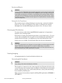
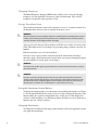
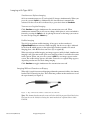
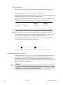
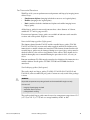
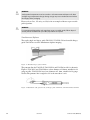
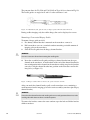
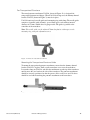
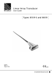
User Guide
Type 8818
Biplane and Endfire Transducer
English
BB1505-F
June 2012
For Professional Users Only
BK MEDICAL
Mileparken 34
2730 Herlev
Denmark
Tel.:+45 4452 8100 / Fax:+45 4452 8199
www.bkmed.com
Email: [email protected]
The serial number of a BK Medical product contains information about the year of manufacture.
To obtain the date of manufacture of a product, please contact your BK Medical representative or write
to us at the email address above, including the product’s serial number (SN number).
BK Medical Customer Satisfaction
Input from our customers helps us improve our products and services. As part of our customer
satisfaction program, we contact a sample of our customers a few months after they receive their orders.
If you receive an email message from us asking for your feedback, we hope you will be willing to
answer some questions about your experience buying and using our products. Your opinions are
important to us. You are of course always welcome to contact us via your BK Medical representative or
by contacting us directly.
If you have comments about the user documentation, please write to us at the email address above.
We would like to hear from you.
© 2012 BK Medical
Information in this document may be subject to change without notice.
Contents
Introduction . . . . . . . . . . . . . . . . . . . . . . . . . . . . . . . . . . . . . . . . . . . . . . . . . . . . . . 5
Indications for Use . . . . . . . . . . . . . . . . . . . . . . . . . . . . . . . . . . . . . . . . . . . . . 5
General Information . . . . . . . . . . . . . . . . . . . . . . . . . . . . . . . . . . . . . . . . . . . . . . . 6
Service and Repair . . . . . . . . . . . . . . . . . . . . . . . . . . . . . . . . . . . . . . . . . . . . . 7
Caring for the Transducer. . . . . . . . . . . . . . . . . . . . . . . . . . . . . . . . . . . . . . . . 7
Cleaning and Disinfection . . . . . . . . . . . . . . . . . . . . . . . . . . . . . . . . . . . . . . . . . . . 7
Starting Imaging . . . . . . . . . . . . . . . . . . . . . . . . . . . . . . . . . . . . . . . . . . . . . . . . . . 7
Connecting the Transducer. . . . . . . . . . . . . . . . . . . . . . . . . . . . . . . . . . . . . . . 7
Changing Frequency. . . . . . . . . . . . . . . . . . . . . . . . . . . . . . . . . . . . . . . . . . . . 8
Using a Transducer Cover . . . . . . . . . . . . . . . . . . . . . . . . . . . . . . . . . . . . . . . 8
Using the Transducer Control Button. . . . . . . . . . . . . . . . . . . . . . . . . . . . . . . 8
Changing Orientation . . . . . . . . . . . . . . . . . . . . . . . . . . . . . . . . . . . . . . . . . . . 8
Imaging with Type 8818 . . . . . . . . . . . . . . . . . . . . . . . . . . . . . . . . . . . . . . . . . . . . 9
Imaging Without Puncture or Biopsy. . . . . . . . . . . . . . . . . . . . . . . . . . . . . . . 9
Contrast Imaging . . . . . . . . . . . . . . . . . . . . . . . . . . . . . . . . . . . . . . . . . . . . . 10
Adjusting Image Area and Using Expanded Sector (Trapezoidal View). . . 10
Puncture and Biopsy Facilities . . . . . . . . . . . . . . . . . . . . . . . . . . . . . . . . . . . . . . 10
For Transrectal Puncture . . . . . . . . . . . . . . . . . . . . . . . . . . . . . . . . . . . . . . . 11
For Transperineal Puncture . . . . . . . . . . . . . . . . . . . . . . . . . . . . . . . . . . . . . 15
Performing Puncture and Biopsy . . . . . . . . . . . . . . . . . . . . . . . . . . . . . . . . . 16
Cleaning after Puncture and Biopsy . . . . . . . . . . . . . . . . . . . . . . . . . . . . . . . 17
3D Imaging . . . . . . . . . . . . . . . . . . . . . . . . . . . . . . . . . . . . . . . . . . . . . . . . . . . . . 17
Magnetic Wheel Mover UA0513. . . . . . . . . . . . . . . . . . . . . . . . . . . . . . . . . 17
Variable Friction Support Arm UA0553 . . . . . . . . . . . . . . . . . . . . . . . . . . . 17
Disposal . . . . . . . . . . . . . . . . . . . . . . . . . . . . . . . . . . . . . . . . . . . . . . . . . . . . . . . . 17
3
4
Introduction
This is the user guide for Type 8818 and must be used together with Care, Cleaning
& Safety which contains important safety information.
Indications for Use
Biplane and Endfire Transducer Type 8818 combines simultaneous biplane imaging
and endfire imaging in a single transducer. Type 8818 is designed for transrectal
procedures.
WARNING
The tip of the 8818 transducer (the part containing the arrays) is very delicate. Handle the
transducer gently, especially when you put it down on a hard surface, for example. Also be
very careful not to bump the tip.
Transverse button
Sagittal/Endfire
button
Tip
Figure 1. Type 8818.
Imaging Plane
8818 contains two convex arrays — one for transverse imaging, and one for sagittal and
endfire imaging. The sagittal array of the 8818 has a total arc of 210°. In both
simultaneous biplane imaging and endfire imaging, the imaging plane uses a 140°
section of the arc. It is important to note that simultaneous biplane imaging and
endfire imaging use different sections of the sagittal array. Figure 2 illustrates which
section of the array simultaneous biplane and endfire use.
8818 User Guide (BB1505-F)
Introduction
5
Simultaneous biplane portion of sagittal array
Endfire portion of sagittal array
Transverse array
Transverse array
Figure 2. Imaging plane for Type 8818.
General Information
Product specifications for this transducer can be found in the Product Data sheet that
accompanies this user guide.
Acoustic output data and data about EMC (electromagnetic compatibility) for this
transducer are in Technical Data (BZ2100) that accompanies this user guide. A full
explanation of acoustic output data is given in your system user guide.
WARNING
If at any time the system malfunctions, or the image is severely distorted or degraded, or you
suspect in any way that the system is not functioning correctly:
• Remove all transducers from contact with the patient.
• Turn off the system. Unplug the system from the wall and make sure it cannot be used
until it has been checked.
• Do not remove the system cover.
• Contact your BK Medical representative or hospital technician.
WARNING
Always keep the exposure level (the acoustic output level and the exposure time) as low as
possible.
6
June 2012
8818 User Guide (BB1505-F)
Service and Repair
WARNING
Service and repair of BK Medical electromedical equipment must be carried out only by the
manufacturer or its authorized representatives. BK Medical reserves the right to disclaim all
responsibility, including but not limited to responsibility for the operating safety, reliability
and performance of equipment serviced or repaired by other parties. After service or repairs
have been carried out, a qualified electrical engineer or hospital technician should verify the
safety of all equipment.
Caring for the Transducer
The transducer may be damaged during use or processing, so it must be checked
before use for cracks or irregularities in the surface. It should also be checked
thoroughly once a month following the procedure in Care, Cleaning & Safety.
Cleaning and Disinfection
To ensure the best results when using BK Medical equipment, it is important to
maintain a strict cleaning routine.
Full details of cleaning and disinfection procedures can be found in Care, Cleaning
& Safety that accompanies this user guide. A list of disinfectants and disinfection
methods that the transducer can withstand are listed in the Product Data sheet.
Sterile covers are available. See the Product Data sheet for more information.
WARNING
Users of this equipment have an obligation and responsibility to provide the highest possible
degree of infection control to patients, co-workers and themselves. To avoid cross
contamination, follow all infection control policies for personnel and equipment that have
been established for your office, department, or hospital.
Starting Imaging
All equipment must be cleaned and disinfected before use.
Connecting the Transducer
WARNING
Keep all plugs and sockets absolutely dry at all times.
The transducer is connected to the system using the array Transducer Socket on the
system. To connect, the transducer plug’s locking lever should first be in a horizontal
position. Align the plug to the system socket and insert securely. Turn the locking
lever clockwise to lock in place.
When connected, the transducer complies with Type BF requirements of EN60601-1
(IEC 60601-1).
8818 User Guide (BB1505-F)
Cleaning and Disinfection
7
Changing Frequency
The Multi-Frequency Imaging (MFI) facility enables you to select the imaging
frequency. See the applicable system user guide for instructions. The selected
frequency is displayed at the top of the screen.
Using a Transducer Cover
The transducer should be enclosed in a transducer cover or a standard condom. See
the Product Data sheet for a list of available transducer covers.
WARNING
Because of reports of severe allergic reactions to medical devices containing latex ( natural
rubber), FDA is advising health-care professionals to identify their latex-sensitive patients
and be prepared to treat allergic reactions promptly.
Apply sterile gel to the tip of the transducer or fill the cover with 1 to 2 ml of sterile
water. This improves the screen images by preventing image artifacts caused by air
bubbles.
Pull the transducer cover over the transducer.
Gel also creates a good acoustic contact between the skin and the transducer;
therefore, apply a small amount to the outside of the cover prior to imaging. Re-apply
the gel frequently to ensure good screen images.
WARNING
Use only water-soluble agents or gels. Petroleum or mineral oil-based materials may harm
the cover materials.
WARNING
Do not use excessive force during insertion. Do not make excessive lateral movements
during or after insertion. Risk of injury or tissue damage to the patient could occur under
certain circumstances. A digital palpation of the rectum may need to be carried out by a
clinician prior to insertion or use of the probe as a precautionary measure.
Using the Transducer Control Button
To change the imaging plane, press the button corresponding to that plane (see Figure
1). Pressing the button activates (starts) or freezes (stops) imaging in that plane. One
button enables the sagittal or longitudinal array. A long press on this button also
activates endfire imaging. A second button enables the transverse array. Each time a
button is pressed, a beep is emitted.
Changing Orientation
To change the orientation of the image on the monitor, refer to the applicable system
user guide for instructions.
8
June 2012
8818 User Guide (BB1505-F)
Imaging with Type 8818
Simultaneous Biplane Imaging
8818 can transmit transverse (T) and sagittal (S) images simultaneously. When you
press the system’s Split key, simultaneous live transmission is automatically
activated. On the screen, this is indicated by a green dot in front of Simultan.
Transverse or Sagittal Imaging
Click Simultan to toggle simultaneous live transmission on or off. When
simultaneous transmission is off, you can change which plane is active and which is
frozen by pressing the Split key or by placing the cursor on the image you want to
be active and pressing the Select key.
Endfire Imaging
Type 8818 can perform endfire imaging. A long press on the transducer’s
Sagittal/Endfire button activates endfire imaging. On the screen, this is indicated
by the letter E, which appears to the right of the transducer number. To switch
imaging plane, click E and select transverse (T) or sagittal (S).
When you activate endfire imaging, one image appears (and by default, simultaneous
imaging is off). You must enable split screen imaging as there is no defined isocenter
in this context. When you press the system’s Split key, two images appear on the
screen. The endfire image appears and either a transverse or sagittal image appears,
depending on what was last used during imaging.
Click Simultan to toggle simultaneous live transmission on or off.
Imaging Without Puncture or Biopsy
When 8818 is used for transrectal imaging without the puncture facilities, the dummy
bracket UA1325 must be in place. This clicks into position on the transducer to cover
the open channel (see Figure 3).
Figure 3. Type 8818 and the dummy channel bracket UA1325.
Note: The dummy bracket must be removed before 8818 is prepared for disinfection.
The bracket can be disinfected using the same methods as explained later under
UA1326.
8818 User Guide (BB1505-F)
Imaging with Type 8818
9
Contrast Imaging
See the system user guide for instructions on how to perform contrast imaging.
Viewing B-Mode and Contrast Images Simultaneously
When performing contrast imaging, use the system's split screen functionality to see
the B-mode image and the contrast image simultaneously.
By default, the system will present one image on top and one on the bottom. The
following table shows where the B-mode and contrast images appear:
Endfire imaging
Transverse plane
imaging
Sagittal plane
imaging
Top image
Contrast
Contrast
B-mode
Bottom image
B-mode
B-mode
Contrast
Adjusting Image Area and Using Expanded Sector (Trapezoidal View)
The width of the image area can be adjusted using the Width key on the system’s
control panel. See the applicable system user guide for instructions.
With the Expanded Sector feature and the 8818, you can increase the transverse
sector angle from a default width of 140° to 180°.
Figure 4. Dotted lines indicate expanded transverse sector on the 8818 transducer.
Puncture and Biopsy Facilities
Puncture and biopsy are possible with 8818. The appropriate puncture attachments
are illustrated in the following pages with a brief description of their uses and
operating instructions. The transducer has an open channel into which the
appropriate puncture accessories fit when the dummy channel bracket (UA1325)
has been removed (see Figure 3).
WARNING
It is essential for the patient’s safety that only the correct puncture attachments, as described
in this guide, are used. Never use unauthorized combinations of transducers and puncture
attachments or other manufacturers’ puncture attachments.
10
June 2012
8818 User Guide (BB1505-F)
For Transrectal Puncture
With Type 8818, you can perform transrectal puncture and biopsy by imaging in one
of three ways:
•
Simultaneous biplane (imaging in both the transverse and sagittal planes).
•
•
Endfire (imaging in the sagittal plane).
Dual (combines both the simultaneous biplane and endfire imaging in one
biopsy guide).
All the biopsy guides for transrectal puncture have a bore diameter of 1.6 mm,
suitable for 17- and 18-gauge needles.
For transrectal puncture, biopsy guides are available in both non-sterile reusable
versions and sterile-packed single-use versions.
Non-sterile biopsy guides (light green)
The dummy channel bracket UA1325 and the reusable biopsy guides (UA1326,
UA1327 and UA1328) are non-sterile when supplied and must be disinfected by
immersion in a suitable solution and autoclaved. The dummy channel bracket and
reusable biopsy guides may be damaged during use or processing, so they must be
checked before use for cracks or irregularities in the surface. They should also be
checked thoroughly once a month following the procedure in Care, Cleaning &
Safety.
Puncture attachment UA1324 must be autoclaved or disinfected by immersion in a
suitable solution. Needle guides UC5302, UC5303 and UC0100 can also be
autoclaved.
Sterile biopsy guides (dark green)
The sterile single-use biopsy guides (UA1322-S, UA1322-S14, UA1323-S and
UA1329-S) come assembled in peel packs. Contents are only sterile if the package
is intact.
WARNING
Disposable components are packaged sterile and are intended for single-use only.
Do not use if:
•
•
•
integrity of packaging is violated
expiration date has passed
package label is missing
The sterile-packed biopsy guides must be stored at a temperature range from +15°C
(+57°F) to +25°C (+77°F) and at a storage humidity of 30% to 80%.
8818 User Guide (BB1505-F)
Puncture and Biopsy Facilities
11
WARNING
Sterile-packed components must be stored in a safe environment and kept out of direct
sunlight. Large temperature changes during storage may cause condensation and violate
the integrity of the packaging.
Please refer to Care, Cleaning and Safety for an example of how to open a sterilepacked product.
WARNING
For contaminated disposables such transducer covers or needle guides, follow disposal
control policies established for your office, department or hospital.
Simultaneous Biplane
The sterile single-use biopsy guide UA1322-S, UA1322-S14 and reusable biopsy
guide UA1326 are used for simultaneous biplane imaging.
Figure 5. Reusable biopsy guide UA1326.
The puncture line for UA1322-S, UA1322-S14 and UA1326 on 8818 is shown in
Figure 6. UA1322-S and UA1326 have a bore diameter of 1.6mm, suitable for 18gauge needles. UA1322-S14 has a bore diameter of 2.1mm, suitable for 14-gauge
needles.The puncture line is angled at 19° to the transducer’s axis.
Figure 6. Illustration of the puncture line for biopsy guide UA1322-S, UA1322-S14 and UA1326.
12
June 2012
8818 User Guide (BB1505-F)
Endfire
The sterile single-use biopsy guide UA1323-S and reusable biopsy guide UA1327
are used in endfire imaging.
Figure 7. Reusable biopsy guide UA1327.
The puncture line for UA1323-S and UA1327 on 8818 is shown in Figure 8. The
needle guide is parallel to the centerline of the transducer.
Figure 8. Illustration of the puncture line for biopsy guides UA1323-S and UA1327.
Dual
The sterile single-use biopsy guide UA1329-S and reusable biopsy guide UA1328
are used in dual imaging. Needle guide UC0100 is marked with a blue band (see
Figure 9). On screen, you will see this corresponds to the color of the puncture line
displayed on the image.
WARNING
Before beginning a puncture or biopsy procedure using dual imaging, ensure that the color
of the puncture line on the system monitor matches that of the needle guide you will insert
your needle into.
Figure 9. Reusable biopsy guide UA1328.
8818 User Guide (BB1505-F)
Puncture and Biopsy Facilities
13
The puncture lines for UA1328 and UA1329-S on Type 8818 are shown in Fig. 10.
The needle guides are angled at 0° and 19° to the transducer’s axis.
Figure 10. Illustration of the puncture line for biopsy guides UA1328 and UA1329-S.
During endfire imaging, only the endfire biopsy line can be displayed on screen.
Mounting a Transrectal Biopsy Guide
To mount a biopsy guide on 8818:
1 If a dummy channel bracket is mounted on the transducer, remove it.
2 Pull a transducer cover or a standard condom containing a suitable amount of
imaging gel over the transducer.
3 Slide the needle guide into the biopsy channel bracket.
WARNING
Do not use excessive force when inserting the needle guide.
4
Insert the assembled needle guide and biopsy channel bracket into the open
channel on the transducer. A small nodule on the end of the channel bracket fits
into an indentation in the channel on the transducer to help you place the bracket
correctly. Click the channel bracket into position on the transducer and lock it
into place (see Figure 11).
Figure 11. Biopsy channel bracket and needle guide mounted on 8818.
After you attach the channel bracket, pull a sterile transducer cover containing a
small amount of sterile imaging gel over the entire assembly (transducer plus biopsy
channel bracket)
WARNING
Ensure that the channel bracket and needle guide are correctly positioned. Never insert the
needle guide while the transducer is inside the patient.
To remove the bracket, remove the outer condom, open the lock and lift the bracket
off the transducer.
14
June 2012
8818 User Guide (BB1505-F)
For Transperineal Puncture
The metal puncture attachment UA1324, shown in Figure 12, is designed for
transperineal puncture and biopsy. When UA1324 is being used, the dummy channel
bracket UA1325 (shown in Figure 3) must be in place.
UA1324 consists of a needle guide and a mounting ring with clamp. The needle guide
comprises 9 parallel guide channels, spaced 5mm apart, each with an internal
diameter of 2.1mm, suitable for a 14-gauge needle. The guide is parallel to the
centerline of the transducer.
Note: The needle guide can be adjusted 70mm lengthwise with respect to the
mounting ring, using the adjustment screw.
Figure 12. Puncture attachment UA1324.
Mounting the Transperineal Puncture Guide
To mount the transperineal puncture attachment, ensure that the dummy channel
bracket UA1325 is in place. Pull a sterile transducer cover over the transducer.
Loosen the clamp on UA1324, and slide the attachment over the tip of the transducer
until it meets the steel stud on the side of the transducer. The puncture attachment
should be correctly positioned so that the groove slides easily over stud. No force
should be used when attaching the puncture attachment to the transducer.
Figure 13. Puncture attachment UA1324 mounted on 8818.
8818 User Guide (BB1505-F)
Puncture and Biopsy Facilities
15
The puncture lines for UA1324 on 8818 are shown in Figure 14.
Figure 14. Illustration of the puncture line for puncture attachment UA1324.
Performing Puncture and Biopsy
WARNING
It is essential for the patient’s safety that only the correct puncture attachments, as described
in this guide, are used. Never use unauthorized combinations of transducers and puncture
attachments or other manufacturers puncture attachments.
Before beginning a puncture or biopsy procedure, always check that the type number of the
transducer and the type number or description of the puncture attachment match exactly
those displayed on the system monitor.
WARNING
The puncture line on the image is an indication of the expected needle path. The needle tip
echo should be monitored at all times so any deviation from the desired path can be
corrected.
If not sterilized, cover the transducer with a sterile transducer cover.
If the transducer cover is damaged when attaching the puncture attachment, replace
it with a new cover.
See the Product Data sheet for a list of available transducer covers.
Superimpose
puncture line
Press the system Puncture or Biopsy control button to superimpose a puncture line
on the image.
If more than one puncture line is available, refer to the applicable system user guide
for instructions on how to change which one appears.
Move the transducer until the puncture line transects the target. Insert the needle and
monitor it as it moves along the puncture line to the target. The needle tip echo will
be seen as a bright dot on the screen.
The puncture line will differ depending on the imaging plane orientation. In the
sagittal plane, the puncture path is indicated by a line of dots. The distance between
each puncture dot is 5mm.
In the transverse plane, a single dot indicates the point at which the needle will
transect the imaging plane.
16
June 2012
8818 User Guide (BB1505-F)
WARNING
If the needle guide is detached from the transducer during interventional procedures, cover
the transducer with a new transducer cover.
If the cover is damaged during interventional procedures, follow the policies of the hospital
or clinic for treatment of the patient under such circumstances.
To remove the puncture line from the image, refer to the applicable system user guide
for instructions.
WARNING
When performing a biopsy, always make sure that the needle is fully drawn back inside the
needle guide before moving the probe.
Cleaning after Puncture and Biopsy
If biological materials are allowed to dry on the transducer, disinfection and
sterilization processes may not be effective. Therefore, you must clean transducers
immediately after use.
Use a suitable brush to make sure that biological material and gel are removed from
all channels and grooves. See Care, Cleaning & Safety for cleaning instructions.
3D Imaging
3D imaging with the 8818 may be carried out in either of two ways:
•
•
Freehand – where the transducer is combined with the appropriate 3D system
software.
Using mover support – where the transducer is combined with the appropriate
3D system software, the Magnetic Wheel Mover UA0513 and the Variable
Friction Arm UA0553.
Magnetic Wheel Mover UA0513
Further information about the Magnetic Wheel Mover UA0513 can be found in the
user guide for the Magnetic Wheel Mover.
Variable Friction Support Arm UA0553
Further information about the Variable Friction Support Arm UA0553 can be found
in the user guide for the Variable Friction Support Arm.
Disposal
When the transducer is scrapped at the end of its life, national rules for the relevant
material in each individual land must be followed. Within the EU, when you discard
the transducer, you must send it to appropriate facilities for recovery and recycling.
See the applicable system user guide for further details.
8818 User Guide (BB1505-F)
3D Imaging
17
WARNING
For contaminated disposals such as transducer covers or needle guides, follow disposal
control policies established for your office, department or hospital.
18
June 2012
8818 User Guide (BB1505-F)
LEGAL MANUFACTURER
: BK Medic al ApS , Milepa rken 34, 2730 Herlev, Denma rk. Tel.: +45 44528100 Fax : +45 44528199 E mail: [email protected]