1
Technical Guide
LINE THERMAL PRINTER
SK1-21
SK1-31
Rev2.2
SK1-31
DECLARATION OF CONFORMITY
Product Name:
Model Number:
Sanei Electric Inc.
5Floor, Taisou Ikebukuro Building, 2-61-1 Ikebukuro,
Toshima-Ku, Tokyo 171-0014, Japan
Thermal Printer
SK1-31
Accessories:
SA13A240 / AC/DC adapter and Power cord
Manufacturer’s Name:
Manufacturer’s address:
The product complies with the following product standards.
CE
EN 55022: 2006+A1 :2007,Class A
EN 61000-3-2: 2006, Class A
EN 61000-3-3: 1995+A1: 2001+A2 : 2005
EN 55024: 1998+A1: 2001+A2: 2003
* In accordance with the council directive 2004/108/EC.
FCC
FCC Part 15 Subpart B, Class A
VCCI
VCCI, Class A
Declared by
2
SK1-21/31
General notice
* The specifications may be changed for product improvement without notice.
* Updated information listed on our website. http://www.sanei-elec.co.jp
* Sanei shall not be responsible for any damages attributable to incorrect operation, handling or
improper operation environments, except those specified in this manual.
* Sanei shall not be responsible for any claim of infringement or alleged infringement
of patents, designs, trademarks, copyrights or other rights brought by a third party
in relation to its products.
* Operate this printer only in the manners as described in the Technical guide.
Otherwise, accidents or problems could possibly occur.
* Data are basically temporary; they cannot be stored or saved either for a long time or
permanently. Please note that Sanei Electric shall not be responsible for any damages or lost
profits resulting from the loss of data attributable to accidents, repairs, tests, and so on.
* If you have any questions, or notice any clerical errors or omissions regarding the information in
the technical guide, please contact your dealer.
* Please note that Sanei Electric shall not be responsible for any results or effects
resulting from operation of this Printer even if the information in the Technical guide.
3
SK1-21/31
Precautions
Symbol display
To use this equipment safety, or to protect the equipment from damage, the following
symbols are used throughout this manual to highlight safety information
The symbol indicates that failure to observe these
Warning
instructions or mishandling of this equipment could
lead to severer injury or death
The symbol indicates that failure to observe these
Caution
instructions or mishandling of this equipment could
lead to injury or only property damage.
Samples of symbol
The symbol indicates caution(including DANGER or WARNING).
The symbol indicates the action is prohibited.
The symbol indicates a required operation that must be performed.
When using the printer
Do not subject the printer to strong shocks by dropping or hitting it.
Avoid using the printer at the following location. It may cause failure.
◆ Locations with much dust, particles, water or oil.
◆ Locations with slanted surfaces or strong vibration.
◆ Locations with direct sunlight.
◆ Locations with temperatures of below -25℃, a relative humidity of 90% or more,
dew condensation caused by extreme temperature change.
◆ Location with electromagnetic noise or corrosive gas.
Do not touch the dot line on the thermal head and driver IC with metal and sandpaper
etc. There is a possibility for damage of those parts.
Do not touch the dot line on the thermal head with your fingures. The contamination
may reduce the printing quality.
Do not use the printer if there is condensation occurs on the thermal head. If the
condensation occurs, keep the power off until condensation evaporates completely.
Do not block the paper exit of the printer.
Do not use a volatile chemical such as thinner or benzene.for maintenance work.
4
SK1-21/31
Do not pull the paper end from the exit forcedly when the printer cover is closed.
Turn off the printer power when trouble such as a paper jam occurs.
Do not use loose paper. It may cause paper jam.
Be careful of handling the thermal head to prevent heat elements and driver IC from
exposure to static electricity.
When setting the printer
The details such as the setting positions of the printer shall be reffered to “Ⅲ-8.
Dimansions”
Set the printer horizontally to the level, and make sure so the level not to be slanted.
Handling printer unit
Warning
◆ Never disassemble or repair the printer ,AC adapter or power cord by yourself.
◆ Do not use any AC adapter and power cord other than those specified.
◆ Do not bend the AC power cord or place heavy objects on it. Doing so may damage
the cord and cause fire or electric shock.
◆ Never use a damaged AC power cord. It may cause fire or electric shock.
◆ Do not drop any metalic objects nor spill coffee,water or any other liquid.
◆ Do not use the printer in a places where it will be exposed to excess moisture
or water spray. It may result in electric shock, short circuit and failure.
◆ Do not connect or disconnect the ACadapter with wet hands. It may result in
electric shock, short circuit and failure.
Caution
As the thermal head may be very hot immediately after printing, do not touch it to
avoid burning your fingers. Be sure that the thermal head is cool before replacing a
paper or cleaning the thermal head.
Do not open the paper cover while printing.
Do not pull the paper when the cover is closed.
◆In the following cases, turn the printer power OFF and unplug the AC power cord from
the outlet.
・Smoke, unusual noises or odd smells are emittied by the printer.
・When metallic objects is dropped or any liquid is spilled inside the printer.
◆Continueous use may lead to printer failure,fire and electric shock.
◆Make sure the fault does not continue and contact dealers for further assistance.
If the printer is not to be used, turn the printer power OFF and leave the AC adapter
disconnected from the outlet.
5
SK1-21/31
Remove the interface cable or AC adapter from the connector or the receptacle by
gripping the connector or the AC plug. Never pull the cable itself.
Doing so may damage the cable or adapter.
Handling Paper Roll
Use the specified paper or equivalent. Use of other paper may reduce life of the
thermal head and cause a decrease in printing quality
Especially sodium(Na+)、potassium(K+) and chlorine(Cl-) containing substances can
remarkably reduce the life of the thermal head.
Store the paper in a dry, cool and dark place.
When pasting printed pages, use water-bnased glue. (starch glue, synthetic glue, etc.)
The surface of thermal paper has been specially treated with a chemical agent to
produce coloring by thermal chemical reaction.
◆ Do not expose the paper for a long time under bright light.
◆ Avoid storing in high temperature, high humidity,damp area and
direct sunlight.
◆ Do not rub the paper with hard objects.
◆ Keep the paper away from organic solvents.
◆ Do not let the paper touch vinyle chloride film, erasers or adhesive tapes for hours.
◆ Do not place he paper on diazo print paper or wet, freshly made paper copies.
◆ Do not touch the paper with wet hands. It may cause fingerprint to be marks on the
paper or smudges.
6
SK1-21/31
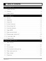
Table of contents
1.General Outlines................................................. 9
1- 1.Product Outlines ........................................................9
1- 2.Features.................................................................9
1- 3.Classification.........................................................10
2.Handling Method................................................ 12
2- 1.Options................................................................12
2- 2.Appearance.............................................................13
2- 3.Status LED.............................................................14
2- 4.Inside Structures .....................................................14
2- 5.Setting Paper Roll ....................................................15
2- 6.Interface Connector ...................................................17
2- 7.Power ON/OFF...........................................................17
2- 8.Paper near-end sensor .................................................17
2- 9.Changing paper holder axis ............................................19
2- 10.Clear paper jams .....................................................21
2- 11.Handling Bezel .......................................................22
3.General specifications......................................... 24
3- 1.Specifications.........................................................24
3- 2.Sensor.................................................................26
3- 3.Printing area..........................................................27
3- 4.Print head and cutter position ........................................28
3- 5.Paper sensor position .................................................29
3- 6.Paper feeding..........................................................30
3- 7.Dimensions.............................................................31
7
SK1-21/31
4.Functions...................................................... 35
4- 1.Self test printing ....................................................35
4- 2.HEX Dump mode..........................................................36
4- 3.Function setting mode .................................................37
4- 4.Setting the memory switch .............................................38
4- 5.Memory switch setting menue ...........................................39
4- 6.Adjusting printing density ............................................41
4- 7.LED display............................................................42
4- 8.Memory.................................................................43
5.Interfaces..................................................... 44
5- 1.USB....................................................................44
5- 2.Serial.................................................................45
5- 3.Power supply...........................................................47
6.Label print.................................................... 48
7.Maintenance.................................................... 52
7- 1.Maintenance............................................................52
7- 2.Service for trouble shooting ..........................................53
8.Command systems............................................... 54
8-1.Command table..........................................................54
8- 2.Data code table .......................................................58
8
SK1-21/31
1.General Outlines
1- 1.Product Outlines
SK1-21(2”)/31(3”) Series is the thermal type Kiosk Printer for the data to be input by computers and
other host systems through Serial(RS232C) and USB.
The versatile functions built in the series make it possible to use for several data outputapplications.
1- 2.Features
■
Small and Ultra-Light Weight, Designed for wide variety of systems and equipments
■
Max 200mm/sec high-speed printing
■
Flexible 3-directions paper setting to be designed to the different installation position
■
Variety of paper core holders (adjustable for 3 different rolls)
■
Available for Barcode printing and 2-dimensions code printing
■
Max φ102mm paper roll as standard specifications
■
Various Sensors built-in : Paper near end, Paper empty, Head open sensor, Black-Mark sensor
(Option), Gap sensor (Option)
■
Wide variety of paper size (58, 60, 80, 83mm)
■
Autoloading function
■
Versatile operationg environment
<Other functions>
z
z
z
z
z
z
z
z
z
z
z
z
Capable of HEX dump printing and test printing.
Line spacing can be freely adjusted.
Graphic printing by bit image.
Downloaded characters and user-defined characters can also be printed.
Paper feed amount can be set freely.
With Ruled Line command, table layouts can be easily printed.
Page Mode allows erect/inverse images, clockwise 90 degrees/counterclockwise 90
degrees and overlapping printing.
Page Mode allows setting the paper length to a maximum of 300mm.
Using the Image Registration command, the printing layout can be set up beforehand.
With the Printing Density command, the printing density can be changed.
The command system conforms to ESC/POS.
Capable of registering print images in internal flash memory.
9
SK1-21/31
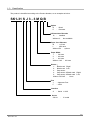
1- 3.Classification
The product is classified according to the Product Number, as an example as below:
SK1-31 S J 3 - 3 M Q B
Option
B :
P :
Bezel
Presenta
2-Dimensions Barcode
Q : Installed
Without Q: Not available
Paper Core Diameter
M
: φ17mm
L
: φ25.4mm
Without M/L: φ12mm
Paper Width
1
: 58.0mm
2
: 60.0mm
3
: 83.0mm
Without 1/2/3 : 80.0mm
Sensor:
1:
Black mark(Right)
2:
Black mark(Left)
3:
Gap sensor
4:
Gap sensor & Black mark(Right)
5:
Gap sensor & Black mark(Left)
Without 1/2/3/4/5 :
None
Font
J : Japanese Font
F : ASCII
Interface
S : Serial +USB
Series
SK1-31
:
3” model
10
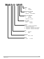
SK1-21/31
SK1-21 S J 3 - 1 M Q B
Option
B :
P :
Bezel
Presenta
2-Dimensions Barcode
Q : Installed
Without Q: Not available
Paper Core Diameter
M
: φ17mm
L
: φ25.4mm
Without M/L:φ12mm
Paper Width
Without : 58.0mm
1
: 60.0mm
Sensor
Without: Reflection Sensor(Right)
1: Reflection Sensor(Left)
2: Gap Sensor + Reflection Sensor(Right)
3: Gap Sensor + Reflection Sensor(left)
Font
J : Japanese
F : ASCII
Interface
S : Serial +USB
Series
SK1-21:
2” model
11
SK1-21/31
2.Handling Method
2- 1.Options
This Series provides the following parts as options:
(These parts can be purchased through the stores/shops you have purchase, and the details of the
optional parts can be inquired to the stores/shops and/or distributors.)
■
Paper Rolls
Make sure to use the paper roll specified as below:
Specifications
P-80-102A
Part No.
TF50KS-E2D
Sensitivity
Standard duration
Paper width
79.5±0.5mm
Thickness
59µm
Roll diameter
Φ102mm
Core
Internal dia. Φ12×External dia.Φ18mm
Thermal paper side
External
No adhesion・No fold
Internal paper end
External paper front
Cut straight and put a seal
A red stripe on one side of the paper
End mark
Width:
2 to 5mm
Length: 500±100mm
■
Cables
・Interface Calbe
・Power-supply cable
・AC Adaptor
・AC code
■
・USB Cable
Paper Roll Holders
Embedded paper holder (HOLDER 1) is sized φ12mm. The different size of holder is available.
Part No. :
Applicable roll holder:
HOLDER 2
φ17mm
Part No. :
Applicable roll paper:
HOLDER 3
φ25.4mm
12
SK1-21/31
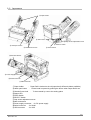
2- 2.Appearance
①Paper Holder
④ Status LED
⑦ Gap Sensor adjustment screw
⑥ SELECT Switch
② Head open button
③ Chassis fixture hole
⑤ FEED Switch
⑧Near End Sensor
⑨ Power-supply Connector
⑩ Serial Connector
⑪ USB Connector
①Paper holder
: Paper Roll is hooked to the roll paper bar(3 different holders available)
②Head open button
: Printer head is opened by pushing the button when Paper Roll is set
③Chassis fixture hole
: To be screwed by uset to the setting place
④Status LED
⑤FEED Switch
⑥SELECT Switch
⑦Gap sensor adjustment screw
⑧Near end sensor
⑨Power supply connector : for DC power supply
⑩Serial connector
: for Serial
⑪USB connector
: for USB
13
SK1-21/31
2- 3.Status LED
④
Status LED
LED shows the error status. Please refer to
“IV-7 error message”.
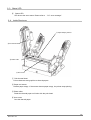
2- 4.Inside Structures
② Paper Eempty Sensor
①Print thermal head
③ Platen roller
④ Auto cutter
① Print thermal head
Prints characters and graphics to thermal papers.
② Paper end sensor
Detects paper empty. If the sensor detects paper empty, the printer stops printing.
③ Platen roller
Feeds the thermal paper on friction with the print head.
④ Auto cutter
Cuts the thermal paper
14
SK1-21/31
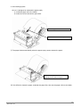
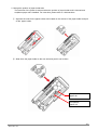
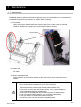
2- 5.Setting Paper Roll
1. Use head open button
①Press the head open button to lift up the print head.
②Install the paper roll as shown in the picture(Printing surface: External (top) side)
②Set the paper roll
①Press the button to open the print head
③Close the print head with the roll end
emerging beyond the paper exit.
・Handle the auto cutter carefully, so not to injure the finger or hand.
・Make sure the print head is completely closed and locked.
・If the paper is jammed, follow the same procedures.
15
SK1-21/31
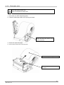
2. Auto-loading system
SK1-31 is designed to autoload the paper easily.
① Install the paper roll to the holder.
② Insert the roll end toward the print head.
①Set the paper roll
②Insert the roll end into the print head
③ The paper feeds automatically when the paper-empty sensor detects the paper.
③ Insert the paper to make the paper
empty sensor detect the paper.
※If it is difficult to insert the paper, autoload the paper first, then set the paper roll into the holder.
16
SK1-21/31
2- 6.Interface Connector
Connect the interface cable after turning the printer power OFF.
Plug in the interface connector observing the correct orientation.
・ Always grip the connector when unplugging the interface cable.
・ Place the interface cable to avoid tripping over it.
2- 7.Power ON/OFF
①Power ON
Provides power to the power connector.
②Power OFF
Disconnects the power through the power connector.
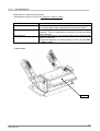
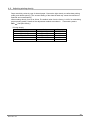
2- 8.Paper near-end sensor
The paper near-end sensor on the paper holder is adjustable for in three positions.
The sensor is positioned along to the paper roll axis at the factory. To adjust and choose a suitable
position, slide it up or down.
・Paper roll diameter: φ102mm
Near end Sensor
Position
1
Position
2
Position
3
Setting position
※When a 102mm roll is
installed, do not position the
sensor in the circled areas.
17
SK1-21/31
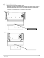
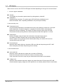
・Paper roll diameter:φ83mm
Position
1
Position
2
Position
3
Near-end sensor
Position
Detectable paper diameter
1
2
3
φ21.0±2mm
φ24.5±2mm
φ35.0±2mm
(Unit:mm)
Paper core
(Internal/External)
φ12.0/18.0mm
φ17.0/21.0mm
φ25.4/31.4mm
・Do not mount the printer on vibrating or slanted surfaces.
・The amount of paper remaining varies by paper roll.
・The external diameter should be used as a reference value.
18
SK1-21/31
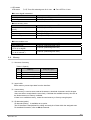
2- 9.Changing paper holder axis
1. How to change the paper holder axis
Three different holder axes are available, and are changeable as follows:
①Pinch together the nobs located on the reverse of the paper holder.
② Pull away from the paper original holder axis.
③Push on the new holder axis until it clicks into place.
19
SK1-21/31
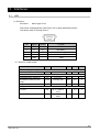
2. Change the position of paper holder axis
The total size of the printer is reduced when the position of paper holder axis is lowered and
anφ83mm paper roll is installed. For exact size, please refer to 3-8 dimensions.
① Squeeze the nobs for the paper holder axis located on the reverse of the paper holder and pull
off the paper holder.
② Slide down the paper holder to the new axis and push it until it clicks.
For φ102mm
paper roll
For φ83mm
paper roll
20
SK1-21/31
2- 10.Clear paper jams
Turn the printer power OFF.
Don’t put fingers into paper exit.
1.First of all, turn OFF the printer power.
2.Press the head open button to lift up the print head.
②Press the head open button to lift
up the print head.
3.Remove the jammed paper.
4.Close the print head and turn ON the power.
③ Remove the jammed paper.
④Close the print head and turn ON
the power.
21
SK1-21/31
2- 11.Handling Bezel
Bezel has two modes shown as below:
Setting Bezel mode is to refer to the subject on memory switch.
。
Bezel Mode
Bezel Mode A/B
Functions
In case paper does not feed 60mm when power is on or after
auto-cutting, paper feeds automatically until it is fed to 60mm.
Bezel Mode A
Detection by Bezel sensor is transmitted by ESC v or GS a
command. Such as suspension of printing is not done by Bezel
sensor detection.
After auto-cutting paper, the next-transmitted data is deleted while
paper is in the bezel.
Bezel sensor detection is recommended by status command ESC
v , GS R1 or GS a.
Bezel Mode B
・Bezel Setting
Bezel
22
SK1-21/31
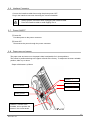
Caution for Bezel sensoring:
1. Bezel sensoring is employed by Reflection sensor.
Such paper roll printed as being blurred and/or distorted is used, reflection sensor may not be
able to detect when black color or the similar on the paper appears at the reflection sensor.
The position of the reflection sensor is shown below in the illustration.
・SK1−31
Bezel Reflection Sensor
・SK1−21
Bezel Reflection Sensor
23
SK1-21/31
3.General specifications
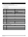
3- 1.Specifications
Model
Printing method
Paper width
Print width
Number of dots
Resolution
Maximum printing speed
Paper holding method
Interface
ASCⅡ
Charactors
Japanese Font
Download
User defined
Printing Width
ASCⅡ16 dots
ASCⅡ 24 dots
Jfont 16 dots
Jfonrt 24 dots
Font
/Dots/
Lines
Paper Sensors
Memory
Logo registration
Barcode
2D bar code(Option)
Command systems
Setting position
Regulation
Printing life
Cutter life
Power supply
Current consumption
Operating environment
Storage environment
SK1-31S F
SK1-31S J
SK1-21S F
SK1-21S J
Direct line thermal
58/60/80/83mm 補足1
58/60mm
54/56/72/80mm
54/56mm
432/448/576/640dot
432/448dot
8dot/mm(203dpi)
Max.200 mm/s
*Note 1
Paper Holder
Serial(Max.115.2kbps), USB2.0
PC437/850/852/857/858/860/863/865/866,WPC1252、
square form of kana (the Japanese syllabary)
JIS X
−
−
0208-1990
available
○
Printing Width:
54/56/72/80mm
8×16 dots(W×H) 54/56/72/80 lines
12×24 dots(W×H) 36/37/48/53 lines
16×16 dots(W×H) 27/28/36/40 lines
24×24dots(W×H) 18/18/24/26 lines
Near end Sensor/Paper empty Sensor
(OPTION) BM(Black mark)
Sensor/Gap Senssor
JIS X
0208-1990
○
Near end Sensor/Reflection Sensor
(OPTION) Gap Sensor
Input buffer 8k bytes
User memory、Non-volatile memory
Download bit image
UPC-A/E、JAN13/8、CODE39、ITF、CODABAR、CODE128
QR、MaxiCode、MicroPDF417、PDF417、DataMatrix
ESC/POS compatible *Note 2
Horizontal surface
VCCI, FCC, CE, CLASS A
Pulse activation 200million pulses or more Note3
Abrasion resistance
150Km or more
Cutting life 1.5 million cuts or more (Thickness 75um or less)
T.B.D (Paper thickness 76um or more)
DC Power supply
DC 24V±5% / TYP 3A (Peak 7.5A)
Standby: 70mA or less
Printing: Average 2.5A *Note 3
Temperature: -20℃ to +60℃
Humidity: 20%RH to 85%RH(No condensation)
Printing quality is guaranteed from+5℃ to +40℃
Temperature: -30℃ to +70℃
Humidity: 10%RH to 90%RH(No condensation)
24
SK1-21/31
Model
Weight
Dimensions
Paper roll
SK1-31S F
SK1-31S J
SK1-21S F
SK1-21S J
630g(Without paper roll)
525g(Without paper roll )
127×145.5×88.5mm(W×D×H
104×145.5×88.5mm(W×D×H
without protruding parts)
without protruding parts)
Paper width: 58 / 60 / 80 / 83 mm Note 4 & supplement
Paper thickness: 59µm to150µm
External dimensions: φ102mm or less
Core diameter:
Internal/External dia. φ12.0mm/18mm
Internal/External dia. φ17.0mm/21mm
Internal/External dia. φ25.4mm/31.4mm
Standard of print density
Part No.
Thickness
TF50KS-E2D
59µm
TF11KS-ET
145µm
P220AC
105µm
PD160
75µm
HP220A
65µm
Print density
1.0
1.2
1.1
1.05
1.0
Fan fold:
The printer prints fan fold paper. For further information,
please contact a local dealer.
*Note1:Use AC adapter, printing rate less than 25%.
*Note2:ESC/POS is registered trademark of Seiko Epson Corporation.
*Note3:DC24.0V, Printing rate 25%, at room temperature
*Note4:Not permitted with the smaller width paper roll.
Friction between the head and the platen roll in the no paper area may degrade print quality.
(Guaranteed area of acceptable temperature and humidity)
Guaranteed area for printing
Humidity
Temperature
25
SK1-21/31
3- 2.Sensor
(1) Paper-end sensor
The paper-end sensor is installed into the paper path and the photo-interrupter detects the
existence of paper in the printer. When the paper runs out, the red LED lights and the printer
goes into error mode and stops in the printing process.
After the paper is replaced, the printer resumes printing.
・Once the paper end sensor sends the paper empty signal, the printer stops printing.
・As soon as the paper end strip appears, replace the paper roll.
(2) Head open sensor
The head open sensor detects whether the print head is open or closed. Once the sensor detects
the head open signal, the printer stops printing and goes OFF-Line, the Error LED lights Red. The
printer resumes printing after the head is closed.
(3) Thermistor
The thermistor built in the print head detects the temperature of the print head.
If printing at a high printing rate for a long time, the print head temperature rises and
the head may become overheated. To prevent overheating, the printer stops printing when the
temperature is beyond a certain level, and blinks the red Error LED.
26
SK1-21/31
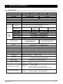
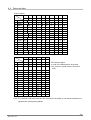
3- 3.Printing area
Printing area
Paper width A ㎜
Margin C ㎜
Print area B ㎜
Feed direction
Paper width/Printing width
58mm /54mm
60mm / 56mm
80mm / 72mm
83mm / 80mm
Margin D ㎜
Print area
A
58
60
80
83
B
54
56
72
80
C
2
2
4
0
D
2
2
4
3
The left and right margins are approximate distance from paper edge and will shift
about ±1mm depending on the paper path, paper position and tolerances.
27
SK1-21/31
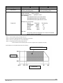
3- 4.Print head and cutter position
Print head and cutter position
Cutting position
Paper feed
Limited length for feedback
Approx.7.0m
Approx.8.6mm
Thermal dot lines
on the print head
・The numeric values in the figure are nominal center values. Leave enough
margin for the cutting position to account for paper flex or variability.
・The position of partial cut is varied by paper width.
・Partial cut is designed to keep the paper at the center of 80mm paper.
28
SK1-21/31
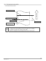
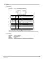
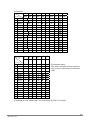
3- 5.Paper sensor position
SK1-31
Paper edge
Thermal dot line
Approx.13.5m
Paper feed
Paper empty
Black mark (L)
Gap sensor
Sensor
Black mark(Left) Note1,2,3
Gap sensor Note1
Paper empty
Black mark(Right) Note 1,2,3
Black mark(R)
Distance from paper edge
(±1.0mm)
7.3mm
29.0mm
50.2mm
72.0mm
Note1: Black mark sensor and gap sensor are embedded in the factory as options.
Note2: Choose the position of Black mark sensor either (L) or (R).
Note3: Black mark on reverse of thermal paper is sensed.
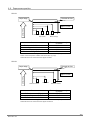
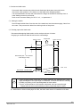
SK1-21
Paper edge
Thermal dot line
Approx.13.5m
Paper feed
Reflection sensor
Gap sensor
Sensor
Reflection sensor (Right)
Gap sensor
Reflection sensor(Left)
Reflection Sensor
Distance from paper edge
(±1.0mm)
54.2mm
19.3mm
4.2mm
Note1: Black mark sensor and gap sensor are embedded in the factory as options.
Note2: Black mark on reverse of thermal paper is sensored.
29
SK1-21/31
3- 6.Paper feeding
(1)Avoid deterioration by backlash feeding
Backlash in the paper feed mechanism may lead to under feeding and crowding of characters on
adjacent lines. Be sure to always turn the paper feed motor 24l steps(3mm)at the start printing
and initialization, and after opening and closing the thermal head.
(2)Notice on graphic printing
If the printer must wait for data from host systems while printing, it will temporarily stop printing
and feeding paper. After the printer receives new data and resumes printing, the paper feeding of
1 to 3 lines may become irregular, especially if it is printing a bit image. In graphic printing, you
may see irregular printing if the single lines of data are specified for Raster bit images.
Specify a minimum of 16 lines or more when graphic data is printed.
(3)
About paper cut
To prevent the printer from paper jam, the printer automatically feeds the paper about 1mm
after cutting process. Therefore printing position is added 1mm to cutting position
30
SK1-21/31
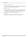
3- 7.Dimensions
External dimensions(Unit:mm)
SK1-31
31
SK1-21/31
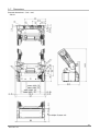
Paper roll axis (Roll diameter φ102mm)
(Unit:mm)
・Paper roll axis (Roll diameter φ83mm)
(Unit:mm)
・
32
SK1-21/31
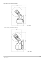
SK1-21
33
SK1-21/31
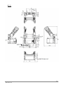
Paper roll axis (Roll diameter φ102mm)
SK1-21
SK1-31
Paper roll axis (Roll diameter φ83mm)
SK1-21
SK1-31
34
SK1-21/31
4.Functions
4- 1.Self test printing
The printer prints characters and barcodes at self test printing.
● Printing method
① Turn ON the power switch while pressing the FEED switch.
② When the LED lights up and the printer starts printing, release the FEED button.
③ After completing the self test printing, the printer goes to Standby mode.
[Printing samples]
35
SK1-21/31
4- 2.HEX Dump mode
Data entered from the computer is printed in hexadecimal numbers and characters.
● Printing method
① With pressing the SELECT button, turn on the power switch.
② When the LED lights up and printer starts printing, release the SELECT button.
③ After printing the following “HEX DUMP MODE”, starts Hexadecimal mode.
④ Prints hexadecimal numbers and characters entered from the host system.
⑤ Press the power switch to cancel the HEX dump mode.
[Example]
36
SK1-21/31
4- 3.Function setting mode
There is a function setting mode to switch register functions in the memory manually.
Functions are called up by the SELECT and FEED buttons and the printer prints registered
functions.
(1) About memory switching
The memory switch is classified as follows.
① COMMON SETTING:
Common functions
② INTERFACE SETTING:
Basic interface functions
(2) Function setting method
1. While pressing the FEED/SELECT button, turn ON the power switch.
2. When the LED lights up and printing starts, release the button.
3. The printer prints out the current setting mode and returns to that function setting.
4. To change the current function setting, press the feed button.
5. Refer to setting flow chart in “Setting of memory switch.”
---COMMON SETTING--PAPER FEED
= OFF
OFFLINE BUSY
= ON
SELECT SENSOR
= Reflection
MARK DETECTION
= OFF
MARK RE-DETECTION = OFF
CHARACTER TABLE
= PC437
PRINT DENSITY
= 100%
PRINT WIDTH
= 80/72
PRINT SPEED
= 200mm/s
CUT AFTER FEED-SW = NON-CUT
USB DEVICE CLASS
= PRINTER
COMMAND MODE
= MODE-A
BEZEL MODE
= NON
Common functions
---INTERFACE SETTING--BAUD RATE
= 115200bps
BIT LENGTH
= 8Bit
PARITY
= Non
BUSY CONTROL
= RTS/CTS
Basic interface functions
---MEMORY SWITCH--0x00 0x20 0x00 0x03 0x1E 0x00
Current memory switch by HEX mode
(Lead from DC2K command)
---CURRENT VOLTAGE--24.0V
Current supply voltage
---SENSOR--Reflection
Transmission
Mark sensor detection level
(Threshold voltage)
= 0.8V
= 0.8V
Table 2
Example
37
SK1-21/31
4- 4.Setting the memory switch
Follow the flow chart to change the parameter. As the setting parameter is printed, choose the right
parameter by manipulating the FEED and SELECT buttons.
After completing the parameters set up, data are stored and the printer goes to standby mode.
■YES : FEED button
■NO
------
: SELECT button
Decide
------ Move to next
Function setting mode
NO
ENTER SETTING ?
YES
ENTER COMMON
SETTING ?
NO
YES
Change the setting of COMMON
PAPER FEED
ENTER INTERFACE
SETTING ?
YES
Change the setting of INTERFACE
・BAUD RATE
・BIT LENGTH
:
:
YES
MODE END
(Finish)
※ Prints the below after
completing the setting:
SETTING COMPLETE
SETTING MODE END.
※ The setting mode is
finished and the printer goes
to standby mode.
Modified data are stored
automatically.
38
SK1-21/31
4- 5.Memory switch setting menue
(1)COMMON SETTING
Menu
PAPER FEED
OFFLINE BUSY
Default
Value
OFF
OFF
ON(10mm)
ON(20mm)
ON(30mm)
ON
Description
Enables/disables paper feed after closing the print head.
・ When paper feed is ON, print feed amount.
(Cut the paper after feeding the paper)
・The value is changeable using the DC2K command.
ON
Enables/disables OFFLINE when the error occurs.
OFF
<At selecting ON>
・OFFLINE is enabled when an error occurs. The printer stops
printing and holds received data until the error is cleared.
<At selecting OFF>
・ONLINE is enabled when error occurs. Receiving data
Is continuously processed and printing data is not stored.
Setting the command and status response are enabled.
SELECT
Reflection
SENSOR
Reflection
Transmission
Selects the mark sensor for label printing.
・Reflection
・・・
Detect by Black mark sensor
・Transmission・・・ Detect by Gap sensor.
MARK
OFF
DETECTION
MARK
OFF
RE-DETECTIN
OFF
Enables/disables the Black mark sensor/Gap sensor functions.
ON
*Enables Black mark and Gap sensor models.
OFF
Enables/disables re-detecting function when the power is
ON
turned ON.
G
CHARACTER
PC437
TABLE
KATAKANA
PC437
/
PC850
PC852
/
PC857
PC858
/
PC863
PC865
/
PC866
Selects the characters.
WPC1252 / PC860
PRINT
100%
DENSITY
80%
Specifies the printing density.
90%
100%
110%
120%
130%
140%
150%
PRINT WIDTH
Comply with
80/72
Selects the paper width.
classified
60/56
(Printing width is set at the factory)
paper width
58/54
83/80
39
SK1-21/31
Menu
Default
Value
MECHANISM
SPPED
200mm/s
110mm/s
130mm/s
150mm/s
170mm/s
190mm/s
200mm/s
ON
OFF
SELLECT
ON
NEAR-END
CUT AFTER
FEED SW
Description
Selects maximum speed
Selects Near end sensor
ON
・・・
・OFF ・・・
NON-CUT
USB DEVICE
CLASS
PRINTER
COMMAND
MODE
BEZEL
MODE
MODE-A
NON
NON-CUT
PARTIAL-CUT
FULL-CUT
PRINTER
COMMUNICATI
ON
MODE-A
MODE-B
NON
MODE-A
MODE-B
activate sensor
cancel sensor
Selects cutting operation after FEED switch is on.
* function added after V1.20
Selects device operation modeUSB
* function added after V1.20
Selects command emmuation
* function added after V1.20
Selects bezel mode
* function added after V1.30
(2)INTERFACE SETTING
Menu
Default
Value
BAUD RATE
115200bps
BIT LENGTH
8bit
PARITY
Non
1200bps
2400bps
4800bps
9600bps
19200bps
38400bps
57600bps
115200bps
8bit
7bit
Non
Odd
Even
RTS / CTS
Xon / Xoff
BUSY
CONTROL
RTS/CTS
Description
Selects the baud rate.
Selects the bit length of serial communication.
Selects the parity of serial communication.
Selects the flow control of serial communication.
40
SK1-21/31
4- 6.Adjusting printing density
Paper sensitivity varies by type of thermal paper. Choose the right density to realize best printing
quality and reliable printing. (The excess heating of the thermal head may cause the reduction of
head life and contamination)
Allows setting density form 50 to 200%. The default value from the factory is 100% for maintaining
proper printing quality. Details of the adjustment method are written in Command systems
DC2 ∼ (Set print density).
Printing density
Part No.
TF50KS-E2D
TF50KS-EY
TF11KS-ET
F230AA
HP-220A
Maker.
Nippon Paper
Nippon Paper
Nippon Paper
Mitsubishi
Mitsubishi
Density
100%
100%
120%
100%
100%
41
SK1-21/31
4- 7.LED display
When an error occurs, the STATUS LED lights or blinks depending on the type of errors as follows.
1.
No error signal is detected.
●
Standby
It is possible to print and the printer waits for printing data by ONLINE.
Initialization
Initialize printer memories. The printer goes OFFLINE during initialization and
status LED blinks. After completing initialization, the printer goes standby.
●
2. Auto-recovery error
●
Temperature error
The print head temperature is increased when heavy-duty printing is continuous. If the print
head temperature exceeds70 degrees C, operation of the print head is automatically
stopped to prevent overheating. The status LED blinks and the printer goes OFFLINE.
The printer resumes printing when the head temperature falls to 60 degrees C or lower.
●
Paper empty
Detects the paper empty through near end sensor and paper empty sensor.
The status LED blinks at paper near end and keeps the printer ONLINE.
After the paper runs out and the printer detects paper empty, the status LED turns On
and the printer goes OFFLINE.
●
Print head open
When the print head is lifted up, the status LED turns ON and the printer goes OFF-LINE.
After closing the print head, the printer goes on standby.
3. Unrecoverable error
●
Auto cutter lock
When the cutter is blocked by a paper jam, the status LED blinks.
Press the head open button to return the cutter to its home position.
If the cutter does not return, keep the print head closed and contact a local dealer.
●
Voltage error
When the printer detects abnormal voltage, the printer blinks the LED and goes OFFLINE.
Check the power supply voltage and if the problem is not cleared, please contact a local dealer.
42
SK1-21/31
4. LED status
LED status
○/◎:Turn ON red and green for 0.1sec
●No error signal is detected
Status
Standby
Initializing
●Auto-recovery error
Status
Temperature error(≒70℃ or
more)
Detect near end
Paper empty
Print head open
●Unrecoverable error
Status
Auto cutter lock
Upper limit voltage error
(≒27.0V or higher)
Lower limit voltage error
(≒18.0V orlower )
●:Turn OFF for 0.1sec
LED
ON
(Green LED)
○●○● (Green LED)
LED
○●○● (Red LED)
○●○● (Green LED)
ON (Red LED)
ON (Red LED)
LED
○◎○◎ (Red and Green LED)
○◎○◎ (Red and green LED)
○◎○◎ (Red and green LED)
4- 8.Memory
(1)Structure of memory
Table1. Capacity
No
Memory
Size(Unit: Byte)
1
Input buffer
8192
2
3
User memory
2D barcode(Option)
8192
34480
(2)Input buffer
Buffer memory stores input data from the interface.
(3)User memory
User memory is used to store external characters, download characters and bit images.
Users are able to manipulate the area freely. Calculate the available memory size due to
the limited amount of memory available.
If there is no available memory, erase the used memory to free up enough space.
(4)2D barcode (option)
2D barcode printing is available as an option.
The 2D barcode is manipulated for editing and analysis of data within the assigned area.
For detailed information, refer to GS Q command.
43
SK1-21/31
5.Interfaces
5- 1.USB
(1) Pin layout
Connector:
Mini-B type 5-PIN
This printer is equipped with USB version 2.0 for high speed data transfer.
The device class is “Printing Device.”
1
5
Pin
Signal
Direction
Function
1
VBUS
-
Detect connect/disconnect of USB
2
D-
I/O
USB data (-)
3
D+
I/O
USB data (+)
4
N.C
5
GND
-
GND
(2)Electronic characteristic
Parameter
Signal
Conditions
Min.
Max.
Unit
4.40
5.25
V
(Power supply voltage)
VBUS
(Input level)
Differential input sensitivity
Differential common mode
range
Single end receiver threshold
VDI
|(D+)-(D-)|
0.2
VCM
Including VDI
0.8
2.5
V
0.8
2.0
V
0.3
V
3.6
V
VSE
(Output level)
“L”Level
VOL
RL of 1.5kΩ to
3.6V
“H”Level
VOH
RL of 15kΩ to
GND
2.8
V
44
SK1-21/31
5- 2.Serial
(1) Pin layout
Connector:
CVILUX
CH87102HA00 or equivalent
9
10
1
2
Pin
Signal
Direction
Function
1
N.C
――
2
DTR
――
DSR loop connect
3
RxD
Input
Serial data input
4
RTS
Output
Request to send
5
TxD
Output
Serial data output
6
CTS
Input
Clear to send
7
DSR
――
DTR loop connect
8
N.C
――
9
GND
――
10
N.C
――
DTR is used to control data transmission to some host systems.
When the host system is communicated by DTR, use loop connect of the host system.
(2) Conditions
Baud rate:
Parity:
Bit length:
Busy control:
1200 to 115200bps
None, Odd, Even
7, 8 bit
Hardware control(RTS/CTS/Software control(XON/XOFF)
45
SK1-21/31
(3) Hardware control
High/Low of RTS signal is used to control data transmission to the host system.
RTS signal becomes low if the receiving buffer is filled out curtain level (①)
The host side should stop sending data if RTS signal is low. If the data in the input buffer is
reduced to curtain level, RTS signal goes high and re-start sending remained data (②)
RTS
RxD
PRINT
PAPER
EMPTY
POWER ON
buffer
①
buffer
②
(4) Software control(XON/XOFF)
Xon(11H)/Xoff(13H) signal is used to control data transmission to the host system.
Xoff signal is sent to host system if the receiving buffer is filled out curtain level.(①)
The host side should stop sending data if Xoff signal is received. If the data in the input
buffer is reduced to curtain level, Xon signal is sent to the host system and re-start sending
remained data (②)
RTS
Xon
Xoff
Xon
Xoff
Xon
TxD
RxD
P R IN T
P AP ER
EM P TY
P OWE R ON
bu ff er
①
bu f fe r
②
46
SK1-21/31
(5)Conditions of input / output signal
Item
Condition
Rate value
Min.
Typ.
Max.
Unit
High input voltage
Low input voltage
RxD、CTS
RxD、CTS
+2.8
-15
―
―
+15
-2.8
V
V
High output voltage
TxD、RTS
(RL=3KΩ)
TxD、RTS
(RL=3KΩ)
+5
―
+15
V
-15
―
-5
V
Low output voltage
5- 3.Power supply
(1) Pin layout
Connector
:
Hirose DF1BZ-4P-2.5DS or equivalent
1
Pin
1
2
3
4
4
Signal
Direction
Function
DC+
−
Power supply (+)
DC-
−
Power supply (-)
※Depending on printing data, large peak current runs in the power cable.
Consider the voltage drop caused by cable impedance and allow enough margin
when choosing the power cable.
47
SK1-21/31
6.Label print
There is the label mode to print the label paper and the receipt paper with black mark.
Optional gap sensor (Transparent photo interrupter) and black mark sensor (Reflective photo
interrupter) are sensed to top of label form.
(1)Set up label printing
1. Set COMMON SETTING in the memory switch. (Refer to IV-5 Memory switch)
・Select the type of sensor by SELECT SENSOR.
・Enable MARKING DETECTION
・Enable MARK RE-DETECTION
2. Set the default value of initial printing information by DC2 L command.
The information includes label length, gap, stopping position after printing label and
top of form.
3. Sensitivity of embedded sensor is changed by the DC2 mrk command.
Adjust sensitivity according to labels. (Refer to command reference I-16)
4. Press FEED button or send DC2 B、DC2 I when the sensor is enabled to re-detect
marking position after replacing the paper or turn the printer power ON.
5. The sensor is detected as paper empty if marking width is beyond 8mm.
6. Command for labels are listed in “Command ReferenceⅠ-16. Label”
(2)Label mode
There are intermittent label mode and continuous label mode installed in the printer.
1. Intermittent label mode
Feed each label to the position of the paper cutter. The printer prints the next label after
back feeding the label. This mode is useful to remove each label by each print.
Always retain the base paper. If the base paper is cut and the distance between edge
of the base paper and the front of the label becomes shorter than 15mm, the label paper is
peeled off while back feeding.
Note1.
Note2.
Note3.
Adjust the cut position by command DC2 L.
Set the amount of back feed not beyond back feeding limit and DC2 L n3.
Thickness and length of labels and base papers may cause unexpected results
during back feeding. Please make sure the label paper works for back feeding.
48
SK1-21/31
2. Continuous label mode
Prints each label continuously without back feed when label paper cannot be fed to
the correct cutter position or it is hard to cut the label at the stopped position.
It is recommended to choose this mode when the height of the label is relatively short or
back feeding cannot be performed.
Refer to the command setting for DC2 L / n3、n4 parameter 0.
(3)Setting the media
Peel off labels within15mm from the end of the media and set the end emerging 10mm from
the cutter. This prevents the label from sticking inside of the printer.
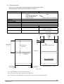
(4)Receipt paper with black mark
Recommend designing black marks on the receipt as shown in below.
No gap type continuous label should use the same design.
12mm or more
Paper feed
12mm or more
4∼6mm
Black mark pitch
25 to 350mm
(Label length+Gap)
(Unit:mm)
Black mark(Reverse side)
Density:PCS value≧0.9
Front(Print surface)
・If PCS of black marks is less than 0.9, black marks are not sensed and the page
might be skipped or the right length not detected. It causes the failure of sensing.
・Prohibit pre-printing in the area designated for black marks.
・There is a feed tolerance ±2% between calculated value and actual length.
Please take into account this tolerance when pre-printed paper is used.
※ The position of black mark is decided by that of black mark.
※ When 58mm/60mm width paper is used, the black mark sensor is installed on left side.
49
SK1-21/31
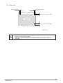
(5)Label specifications
SK1-31 prints label paper with black marks and without black marks.
Use label paper complying with the following conditions.
Item
Recommendable media
Roll diameter
Label core
Base paper width
Label width
Length
Label gap
Rolling up direction
Black mark size
Density of black mark
No black mark
With black mark
HW76B(Nippon Paper Ind.)
Length:
94µm
Thickness of base paper:
60µm
Color on base paper:
White
Total thickness:
154µm or less(incl. adhesive)
Φ102mm or less
Φ25.4(Internal dia.)×Φ31.4(External dia.)mm
57.5±0.5mm/59.5±0.5mm/79.5±0.5mm
54±0.5mm/56±0.5mm/76±0.5mm
25 to 350mm
3 to 6mm
0 to 6mm
Label surface is outside of a roll
Width:12mm or more
−
Length:4 to 6mm
Ink:Reflective ratio should be
−
7% or less.
12 or more
Paper feed
12 or more
4∼6
Label pitch
L1+L2
Label length (L1)
25 to 350
Black mark(Reverse side)
Paper feed
Label gap (L2)
3 to 6mm
Front(Label surface)
1.75 or more
1.75 or more
Black mark position
Note2,3
(Unit:mm)
Note 1. Above illustration shows the paper width 80.0mm..
Note 2. The position of black mark is decided by that of black mark.
Note 3. When 58mm/60mm width paper is used, the black mark sensor must be installed on left side.
50
SK1-21/31
(6)Printing area
3±2(Left margin)
3±2(Right margin)
2.5 or more(Upper margin)
Print area
2.5 or more(Lower margin)
(Unit:mm)
・The tolerance of the embedded sensor and initial printing position varies about
±2mm from calculated position.
・Take into account the tolerance of paper feed about ±2% when a label is
designed.
51
SK1-21/31
7.Maintenance
7- 1.Maintenance
Periodically clean the printer to maintain the printing quality and avoid failures. It is recommended
to maintain the printer every 6 months or 1 million lines of printing.
(1)Print head
When cleaning the thermal dot line on the print head, use a cotton swab with alcohol
(ethanol, methanol or Isopropyl alcohol) and wipe off stains and dust.
Thermal dot line
(2)Platen roller
When cleaning the platen roller, use a dry soft cloth and wipe off the stain with rotating
the roller.
(3)Sensor and peripherals
Clean the stain, dust and paper powder on the paper empty sensor and paper cover
sensor.
・ Prior to maintenance work, be sure to turn OFF the printer.
・ Avoid cleaning the print head immediately because the print head is hot.
Start maintenance work after the thermal head becomes cool.
・ Do not touch the print head with fingers directly. It may cause damage by
electrostatic discharge and contamination.
・ Do not touch the thermal head dot line with bare hands or metal objects.
・ Do not use volatile chemical agents, such as thinner and benzene.
・ Do not get moisture or spill liquids inside of the printer.
・ Turn ON the printer only after alcohol is completely dried.
52
SK1-21/31
7- 2.Service for trouble shooting
For maintenance and service, please contact your Sanei local distributors or the following address.
Sanei Electric Inc.
Overseas sales division
5F. Taisou-Ikebukuro Bldg
2-61-1 Ikebukuro, Toshima-Ku, Tokyo 171-0014, Japan
TEL: 81-3-3986-1188
FAX: 81-3-3988-5876
53
SK1-21/31
8.Command systems
Command systems are compatible with ESC/POS.
The details please refer to separate volume “command reference”.
8-1.Command table
1. Paper feed command
Command
Standard mode
CR
Carriage return / Line feed
LF
Carriage return / Line feed
FF
Page length printing
ESC C
ESC J
ESC j
ESC d
Set the page length
Printing and feed forward
Printing and feed backward
Printing and consecutive line feed
2.Tab command
Command
Standard mode
HT
Horizontal tab
ESC D
Set horizontal tab
3.Format command
Command
Standard mode
ESC 2
Set the initial linefeed value
ESC 3
Set the linefeed value
ESC SP
Set the left margin
GS L
Set the right margin
GS W
Set the printing area width
ESC $
Set absolute position of the
Printing area
ESC a
Align the position
Page mode
Retrieve page memory / Carriage return
Retrieve page memory / Carriage return
Printing in page mode and returning to
standard mode
(Setting only)
Move Y axis in the forward direction
Move Y axis in the backward direction
Consecutive line feed
Page mode
Page mode
(Setting only)
(Setting only)
(Setting only)
4.Character modification command
Command
Standard mode
Page mode
ESC !
Modify character specifications in a batch
ESC G
Specify the bold character / cancel
ESC E
ESC {
Specify inverse printing / cancel
Specify inverse printing / cancel
ESC Specify underline / cancel
GS !
Set a character size
GS B
Specify the black and white reverse character / cancel
54
SK1-21/31
5.Character Selection Command
Command
Standard mode
Page mode
ESC M
Choose a character font
ESC R
Choose an international character
ESC t
Choose the character code table
ESC &
Erase a download character
ESC ?
Specify and cancel a download character
ESC %
Choose an international character
6.Bit Image Command
Command
Standard mode
ESC *
Specify the bit image
GS *
Register the downloaded bit image
GS /
Print download bit image
DC2 V
Print Raster bit image
DC2 v
Print compressed raster bit image
7.Page Mode Command
Command
Standard mode
ESC L
Select the page mode
ESC S
(Invalid)
ESC FF
(Invalid)
CAN
Erase the print buffer
ESC T
(Invalid)
ESC W
(Invalid)
Page mode
Page mode
(Invalid)
Select the standard mode
Print all page mode memories.
Clear page mode memories
Select printing direction and initial position
Defining the print area
8.Peripheral Equipment Command
Command
Standard mode
Page mode
ESC =
Select the peripheral equipment
ESC c 3
Select valid and invalid for paper empty signal
ESC c 5
Valid and Invalid of panel switch
ESC i
Full cut
ESC m
Partial cut
GS V
Cut the paper
9. Response Command(Installed in Serial interface)
Command
Standard mode
Page mode
Valid / Invalid of automatic status transmission
GS a
Transmit status
GS r
GS E
Answer the string
GS R1
Check printer status
55
SK1-21/31
10.Kanji Command (2 byte code)
Command
Standard mode
Page mode
FS &
Specify the Kanji mode
FS .
Cancel the Kanji mode
FS C
Choose the Kanji code system
FS S
Set the inter character space
FS !
Specify the batch mode
FS Set and cancel the underline
FS W
Specify and cancel the double-height and double-width
FS 2
User defined character registration
11.Printing Image Registration Command
Command
Standard mode
Page mode
FS Q
Specification of image registration onto the nonvolatile memory
FS R
Image registration canceling in the nonvolatile memory
FS O
Printing the image registered in the nonvolatile memory
FS P
Canceling of printing of the image registered in the nonvolatile memory
12.Ruled Line Command
Command
Standard mode
Page mode
DC3 A
Choose ruled line buffer A
DC3 B
Choose ruled line buffer B
DC3 C
Clear the ruled line buffer
DC3 D
Write dot specification to the ruled line buffer
DC3 L
Write line specification of the ruled line buffer
DC3 +
Enable the ruled line printing mode
DC3 Disable the ruled line printing mode
DC3 P
Execute printing of 1 dot ruled line
13.Function Setting Command
Command Standard mode
Page mode
Initialization
ESC @
DC2 D
Reserve and release a download character registration area
DC2 G
Reserve and release a user-defined character registration area
Set printing density
DC2 ∼
DC2 K
Set the memory switch
14.Barcode Command
Command Standard mode
GS H
Set the HRI character printing
GS h
Set the barcode height
GS w
Set the barcode width
GS k
Print barcode
Page mode
56
SK1-21/31
15.2D Barcode Command(Option)
Command Standard mode
Page mode
GS Q
Print two dimensional barcode
(PDF417, MicroPDF417, DataMatrix, MaxiCode, QRCode )
GS S
Change the cell size
16.Label Command
Command Standard mode
DC2 L
Set the label
DC2 l
Detect marking position
DC2 B
Re-detect marking position
DC2 mrk
Set marking threshold
Page mode
57
SK1-21/31
8- 2.Data code table
PC437 system
High-order bit
0
Low-order bit
0
1
2
3
4
5
6
7
8
9
A
B
C
D
E
F
0000
0001
0010
0011
0100
0101
0110
0111
1000
1001
1010
1011
1100
1101
1110
1111
High-order bit
Low-order bit
1
2
3
4
5
6
7
8
9
0000 0001 0010 0011 0100 0101 0110 0111 1000 1001
DLE
DC2
DC3
EOT
ENQ
CAN
HT
LF
FF
CR
ESC
FS
GS
A
B
SP
!
"
#
$
%
&
'
(
)
*
+
,
.
/
0
1
2
3
4
5
6
7
8
9
:
;
<
=
>
?
@
A
B
C
D
E
F
G
H
I
J
K
L
M
N
O
P
Q
R
S
T
U
V
W
X
Y
Z
[
\
]
^
_
C
D
E
F
a
b
c
d
e
f
g
h
i
j
k
l
m
n
o
p
q
r
s
t
u
v
w
x
y
z
{
│
}
SP
«
¸
È
‚
‰
‡
Â
Á
Í
Î
Ë
Ô
Ó
Ï
ƒ
≈
…
Ê
∆
Ù
ˆ
Ú
˚
˘
ˇ
÷
‹
¢
£
¥
1010 1011 1100 1101 1110 1111
0
1
2
0000
0001
0010
·
Ì
Û
└
┴
┬
┸
┯
┰
α
β
Γ
≡
±
3
4
5
6
7
8
9
A
B
C
D
E
F
0011
0100
0101
0110
0111
1000
1001
1010
1011
1100
1101
1110
1111
˙
Ò
—
™
∫
¿
½
¼
¡
«
»
│
┤
┥
┨
┫
┃
┓
┛
┐
├
─
┼
┝
┠
┗
┏
┻
┳
┣
━
╋
┷
╂
┿
┘
┌
π
Σ
σ
μ
τ
φ
θ
Ω
δ
∞
Ø
∈
∩
÷
゚
・
√
²
SP
・SP indicates space.
・A code in the blank section is ignored.
・The content in a bold frame is a function
code.
Note: The character code table indicates bits arranged in the shape of a character and does not
represent an actual printing pattern.
58
SK1-21/31
KATAKANA
High-order bit
Low-order bit
0
1
2
3
4
5
6
7
8
9
A
B
C
D
E
F
0000
0001
0010
0011
0100
0101
0110
0111
1000
1001
1010
1011
1100
1101
1110
1111
High-order
bit
0
1
2
3
4
5
6
7
*
8
*
9
0000 0001 0010 0011 0100 0101 0110 0111 1000 1001
DLE
DC2
DC3
EOT
ENQ
CAN
HT
LF
FF
CR
ESC
FS
GS
A
B
SP
!
"
#
$
%
&
'
(
)
*
+
,
.
/
0
1
2
3
4
5
6
7
8
9
:
;
<
=
>
?
@
A
B
C
D
E
F
G
H
I
J
K
L
M
N
O
P
Q
R
S
T
U
V
W
X
Y
Z
[
¥
]
^
_
*
C
D
E
*
F
a
b
c
d
e
f
g
h
i
j
k
l
m
n
o
p
q
r
s
t
u
v
w
x
y
z
{
│
}
┼
┴
┬
┤
├
 ̄
─
│
┌
┐
└
┘
1010 1011 1100 1101 1110 1111
Low-order bit
0
1
2
0000
0001
0010
SP
。
「
ー
ア
イ
タ
チ
ツ
ミ
ム
メ
×
円
年
3
4
5
6
7
8
9
A
B
C
D
E
F
0011
0100
0101
0110
0111
1000
1001
1010
1011
1100
1101
1110
1111
」
、
・
ヲ
ァ
ィ
ゥ
ェ
ォ
ャ
ュ
ョ
ッ
ウ
エ
オ
カ
キ
ク
ケ
コ
サ
シ
ス
セ
ソ
テ
ト
ナ
ニ
ヌ
ネ
ノ
ハ
ヒ
フ
ヘ
ホ
マ
モ
ヤ
ユ
ヨ
ラ
リ
ル
レ
ロ
ワ
ン
゛
゜
™
©
®
ß
●
○
/
\
月
日
時
分
秒
〒
市
区
町
村
人
・SP indicates space.
・The code in the blank section is ignored.
・The content in a bold frame is a function
code.
*A character in a row marked with * is not printed in the SHIFT JIS CODE.
59
SK1-21/31
PC850 system
0
High-order bit
1
2
3
4
5
6
7
8
9
0000 0001 0010 0011 0100 0101 0110 0111 1000 1001
Low-order bit
0
1
2
3
4
5
6
7
8
9
A
B
C
D
E
F
0000
0001
0010
0011
0100
0101
0110
0111
1000
1001
1010
1011
1100
1101
1110
1111
High-order
bit
DLE
DC2
DC3
EOT
ENQ
CAN
HT
LF
FF
CR
ESC
FS
GS
A
B
SP
!
"
#
$
%
&
'
(
)
*
+
,
.
/
0
1
2
3
4
5
6
7
8
9
:
;
<
=
>
?
@
A
B
C
D
E
F
G
H
I
J
K
L
M
N
O
P
Q
R
S
T
U
V
W
X
Y
Z
[
\
]
^
_
C
D
E
F
a
b
c
d
e
f
g
h
i
j
k
l
m
n
o
p
q
r
s
t
u
v
w
x
y
z
{
│
}
«
¸
È
‚
‰
‡
Â
Á
Í
Î
Ë
Ô
Ó
Ï
ƒ
≈
…
Ê
∆
Ù
ˆ
Ú
û
ù
ˇ
Ö
Ü
ø
£
Ø
×
1010 1011 1100 1101 1110 1111
Low-order bit
0
1
2
3
4
5
6
7
8
9
A
B
C
D
E
F
0000
0001
0010
0011
0100
0101
0110
0111
1000
1001
1010
1011
1100
1101
1110
1111
á
í
ó
ú
ñ
Ñ
™
∫
¿
®
¬
¡
«
»
│
┤
Á
Â
À
©
┫
┃
┓
┛
┐
└
┴
┬
├
─
┼
ã
Ã
┗
┏
┻
┳
┣
━
╋
¤
Ð
Ð
Ê
Ë
È
Í
Î
Ï
┘
┌
Ì
Ó
ß
Ô
Ò
õ
Õ
µ
Þ
þ
Ú
Û
Ù
ý
Ý
¯
´
±
¶
§
÷
¸
º
¨
·
¹
³
²
・SP indicates space.
・A code in the blank section is ignored.
・The content in a bold frame is a function code
Note: The character code table indicates bits arranged in the shape of a character and does not
represent an actual printing pattern.
60
SK1-21/31