1
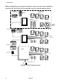
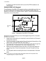
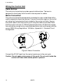
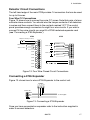
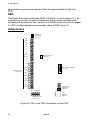
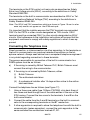
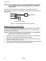
3. Installation
The terminals on the 9750 control unit main pcb are described as Safety
Extra-Low Voltage circuits (SELV), according to the definitions in Safety
Standard EN60 950.
The terminals on the built in communicator are described as SELV or Telecommunications Network Voltage (TNV) according to the definitions in
Safety Standard EN60 950.
Note: The SELV and TNV connections which are shown in Figure 16 are for reference only and do not appear on the 9750 main pcb.
It is important that the installer ensures that TNV terminals are connected
ONLY to the PSTN or other circuits designated as TNV circuits. SELV
terminals must be connected ONLY to other circuits designated as SELV
circuits. Strict adherence to the installation instructions will ensure that the
equipment continues to comply with safety regulations to which it was approved.
Connecting the Telephone Line
Direct connection, or interconnection via other apparatus, to the terminals on
the built in communicator can produce hazardous conditions on the telephone network. Always seek advice from a competent telephone engineer if
in any doubt regarding connection to these terminals.
The person responsible for connection of the built in communicator to a
PABX system must be as follows:
a) If the wiring is owned by British Telecom PLC, British Telecom must
connect the wiring to the communicator.
b) If the wiring is not owned by British Telecom, either:
(i) British Telecom
(ii)
The authorised maintainer
(iii) A professional installer after 14 days written notice to the authorised maintainer.
Connect the telephone line as follows (see Figure 17):
1. Using a three core cable (type 1/05mm CW1308), strip back 5mm of
two cores and feed through one of the cable entries in the rear of the
9750 casing. Connect the two cores to the terminals, A and B on the
built communicator.
2. Connect the cable from the A and B terminals on the built in communicator to the corresponding terminals on the BT master box.
3. If other apparatus is required to share the telephone line with the built in
communicator (series apparatus), connect the main apparatus to the
series switched line connections marked A1, B1.
496478
23