1
3. Installation
Wiring Keyswitches
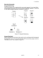
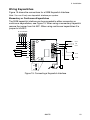
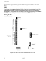
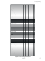
Figure 15 shows the connections for a 9928 Keyswitch Interface.
Note: You can fit only one keyswitch interface per system.
Momentary or Continuous Keyswitches
The 9928 keyswitch interface can be connected to either momentary or
continuous keyswitches, see Figure 15. When using a momentary keyswitch
remove the jumper from link M/C. When using continuous keyswitches fit a
jumper to link M/C.
0V 12V CLK DATA
9928
0V
Set A
12V
0V
Off
CLK
KS2
Set B
DATA
KS1
ET
RDY
Set A
PA
SET
Set B
TAMP
M/C
M/C
M/C
Figure 15. Connecting a Keyswitch Interface
496478
19