1
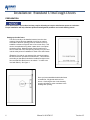
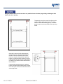
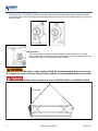
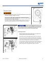
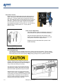
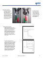
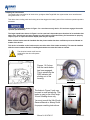
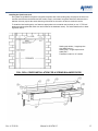
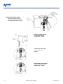
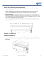
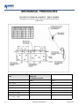
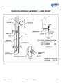
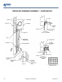
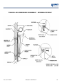
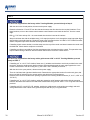
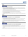
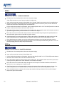
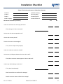
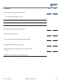
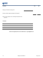
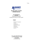
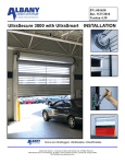
P/N: 6410T0015
Rev: 4/22/2010
Version 4.2
UltraTough M&I Mechanical
INSTALLATION
Doors are UltraRugged, UltraReliable, UltraAffordable.
Albany Door Systems - A Company of Albany International Corp. All Rights Reserved
1080 Maritime Drive, Port Washington, WI 53074 - 975-A Old Norcross Road, Lawrenceville, Georgia 30046
262-268-9885 www.albanydoors.com
STATEMENT OF WARRANTY
UltraTough M&I, UltraBig M&I, PosiDrive M&I High Speed Doors
EXCLUSIVE LIFETIME SBR FABRIC WARRANTY
Albany Door Systems warrants to the original owner of the door that the styrene-butadiene rubber (SBR) fabric door
panel (curtain) will be free of defects in materials and workmanship for the lifetime of the door. Door panels (curtains)
made of EPDM are warranted for a period of five (5) years. This warranty covers material failure under normal wear conditions; it does not cover labor, polyethylene terephthalate (PET) weave, windlok, roll strips, and windows after the first
twelve (12) months. Use of petroleum-based products on the door panel (curtain) will void this warranty.
ONE-YEAR WARRANTY ON MECHANICAL AND ELECTRICAL COMPONENTS
Albany Door Systems warrants to the original owner of the door that the mechanical and electrical components will be
free from defects in material and workmanship for a period of one (1) year from the date of shipment.. The warranty does
not cover fuses, heat lamp elements, bulbs, seals and straps.
Only defects brought to the attention of Albany Door Systems during the warranty period will be covered by this warranty.
Albany Door Systems will replace component parts covered by this warranty, which are found to be defective upon inspection by an Albany Door Systems representative. Installation or use of parts other than those authorized by Albany
Door Systems will void this warranty.
PARTS AND ASSEMBLIES sold separately by Albany Door Systems that fail due to defects in material or workmanship
within ninety (90) days from the date of shipment will be replaced under warranty provided installation has been carried
out in accordance with all Albany Door Systems procedures. This warranty is limited to providing a replacement part only.
This warranty does not cover freight, special charges, or any costs associated with the installation of the replacement part.
This warranty covers material failure under normal wear conditions; it does not cover damage caused by collision or other
abuse of the product. Adjustments made to the control panel or to the mechanical operation of the door without the authorization of Albany Door Systems will void this warranty. Any changes made to product configuration without the express
written approval from Albany Door Systems may null and void this warranty.
Albany Door Systems’ obligations under this warranty are limited to repairing or replacing the defective part including
labor and Albany Door Systems shall not be responsible for any other losses or damages due to the operation of any
door or parts covered by this warranty. Warranty parts will be shipped regular ground freight at the expense of Albany
Door Systems.
This warranty shall be void in its entirety if the failure of any product shall be caused by any installation, operation, or maintenance of the product which does not conform with the requirements set forth by the seller in the applicable product
manuals or is in the result of any cause other than a defect in the material or workmanship of the product.
No other oral or written representations made by Albany Door Systems or its agents are a part of this warranty unless
specifically set forth in writing by an authorized Albany Door Systems official.
THE ABOVE SET FORTH WARRANTY IS SELLER'S SOLE WARRANTY. SELLER MAKES NO OTHER WARRANTY OF ANY
KIND WHATSOEVER, EXPRESSED OR IMPLIED; AND ALL IMPLIED WARRANTIES OF MERCHANTABILITY AND FITNESS
FOR A PARTICULAR PURPOSE WHICH EXCEED THE AFORESTATED OBLIGATION ARE HEREBY DISCLAIMED BY
SELLER AND EXCLUDED FROM THIS AGREEMENT.
WARNING
Do not install, operate or service the product unless you have read and understand
the safety practices, warnings, installation and maintenance instructions contained
in this manual.
Albany Door Systems - A Company of Albany International Corp. All Rights Reserved
1080 Maritime Drive, Port Washington, WI 53074 - 975-A Old Norcross Road, Lawrenceville, Georgia 30045
262-268-9885 or 877-9252468
v4202010
2
Manual # 6410T0015
Version 4.2
INTRODUCTION
The contents of this manual are designed to help you install UltraTough M&I high speed doors.
DO NOT begin to install the high speed door unless you have read through the instructions in
this manual.
The safety alert symbol is used to identify safety information about hazards that can
result in personal injury. A signal word (DANGER, WARNING, or CAUTION) is used
with the safety alert symbol to indicate the likelihood and the potential severity of injury. In addition, a hazard symbol may be used to represent the type of hazard.
DANGER indicates a hazard that, if not avoided, will
result in death or serious injury.
WARNING indicates a hazard that, if not avoided,
could result in death or serious injury.
CAUTION indicates a hazard that, if not avoided,
might result in minor or moderate injury.
CAUTION, when used without the alert symbol, indicates a situation that could result in damage to the
door.
NOTICE is used to inform you of a method, reference, or procedure that could assist with specific
operations or procedures.
Other symbols that may be used in this manual are:
Lock Out / Tag Out
Rev. 4/22/2010
Crushing
Fire
Manual # 6410T0015
Shock
Read Manual
3
ALBANY DOOR SYSTEMS CONTACT INFORMATION
Port Washington, WI
1080 Maritime Drive, Port Washington, WI 53074
Phone: 262-268-9885 Fax: 262-268-9895
Technical Support: 262-268-9885
www.albanydoors.com / [email protected]
Email: [email protected]
Lawrenceville, GA
975 A Old Norcross Road, Lawrenceville, GA 30046
Phone: 262-268-9885 Fax: 262-268-9895
Technical Support: 262-268-9885
www.albanydoors.com / [email protected]
Email: [email protected]
4
Manual # 6410T0015
Version 4.2
Delivery and Inspection
TOOLS AND MATERIALS REQUIRED
Improper installation of anchoring devices or installation into aged or unsound concrete block, or other
wall material may result in premature wear, product
failure, property damage, or serious personal injury.
Personnel
Two people to install the door
One person qualified to operate forklift, hoist, or
crane
One electrician to install and connect the control
panel and all electrical wiring
Tools
Assorted wrenches
Tape measure
Carpenter‟s square
Level (4ft minimum recommended)
Lifting device (fork lift, hoist, crane)
Lock-Out Tag-out all electrical power supplied to the
door before making any electrical installations or
connections. Also Lock-out Tag-out any equipment
near the installation site if that equipment may be
inadvertently operated into the area used to assemble and install the door. Failure to properly deenergize electrical circuits and disable equipment during
installation and/or maintenance could result in
death or serious injury.
Lifting Straps
2 ladders or personnel lifts (tall enough to
reach above the door head)
Other tools as needed for the type of anchoring
chosen
Materials
Anchors appropriate for the type of wall the
door and accessories are to be installed
onto. Albany Door Systems recommends
through-bolting doors whenever possible.
Wire as specified on the electrical schematic
Electrical supplies needed to comply with all
regulating body electrical codes and standards.
Use proper lifting equipment and techniques. Properly secure all loads. Failure to properly secure all
lifting loads could result in death or serious injury.
Secure the work area so that persons
not working directly on the installation
do not enter the work area.
UNPACKING AND PREPARING
SITE PREPARATION
Electrical Supply
Qualified electrician must make all electrical
mountings and connections in accordance with
all applicable regulating body(s) electrical codes
and standards. The control box is equipped
with a 3-phase AC fused disconnect.
Door Opening
1.Are the door jambs and support wall structurally sound providing a flat surface for the side
columns to mount against?
2.Check the width and height of the door opening
and verify the measurements against the
dimensions of the door.
3.Is the opening square? Plumb?
4.Is the floor level across the opening?
Make all necessary structural repairs and improvements
to provide a “yes” answer to each of the questions above.
Rev. 4/22/2010
1.Inspect and unpack the components. Report any
damage immediately to Albany Door Systems at
(262)-268-9885. Refer to the serial number tag located on the door side frame.
2.DO NOT cut the banding which holds the door in a roll
until instructed to do so in a later procedure.
The door panel and roll assembly could be
damaged. Use evenly spaced padded supports to prevent rips, tears, or bending of
the roll assembly. Failure to protect the roll
assembly could result in damage to the
door.
Manual # 6410T0015
5
Installation: Standard UltraTough Doors
PREPARATION
Some wall surfaces are not ideal and may require shimming to keep the side frames square to each other.
Proper installation will help eliminate photocell misalignment problems and curtain binding issues.
Setting up the side frame
The door is usually to be installed centered over the door
opening. Also at this time establish a level line or mark on
each side of the door opening (must be marked in order to
establish a reference height in case of an uneven floor). This
can be accomplished using either a water level or an optical
measuring device. Measuring down from this mark to the
floor on each side of the door opening will tell you if your floor
is level at the points of installation for each of the side frames.
(Example: If on side A, you measure from your level mark to
the floor and it 46” and side B it measures 47”. This measurement tells you that Side A should be installed first right on the
floor and that Side B will have to be raised 1” in order to be
level with Side A). See figure 1.
Once you have established which side frame
to install first, fully plumb and level it as
shown. Centering the door in the doorway
opening will allow for minor variations in the
existing door opening.
6
Manual # 6410T0015
Version 4.2
Along the outside of each side frame there are predrilled holes for either plug welding or bolting the side
frame to the door opening.
Temporarily secure the second side frame to the
opening. Attach width gauge across the upper
section of both side frames (figure 4). This width
gauge is equal to the manufactured door opening
width.
Once this is done verify all dimensions are
plumb and square. The door width distance
should be the same between the two side
frames at any point along the door opening
height. Once this has been confirmed, permanently attach both side frames by either bolting
or welding. Plug weld or bolt the side frame to
the doorframe.
If plug welding the side frames you will also
have to tack weld inside leading edge of frame
to the door jamb across from the same location
as the plug welds.
Rev. 4/22/2010
Manual # 6410T0015
7
Preparing the header assembly for lifting
Loosen and remove the lower idler barrel bolt and move the idler barrel forward before lifting the header assembly.
You will also want to lower the bottom beam assembly below the idler barrel with the manual hoist prior to rigging the
header for lifting.
Lifting locations
There are eyebolts for lifting the header assembly into place located on the header
plates. Attach cable or chain that is rated for the weight of the header assembly. Be sure
to balance the header assembly before lifting into place.
The cable or chain used for lifting the header assembly must not exceed a
45 angle from vertical. Vertical lifting from the eyebolts is recommended whenever possible.
A falling header assembly can result in SEVERE INJURY and POSSIBLY DEATH!
45o or Less
8
Manual # 6410T0015
Version 4.2
Lifting with a fork lift
Never lift using the bottom beam or the idler barrel between the forks and
the header assembly, damage can occur.
Place the forks of the forklift up under the top roll and not the header
framework or the Idler Barrel. DAMAGE WILL OCCUR if the door is lifted
by the idler barrel or header framework.
Be careful to have the header assembly properly balanced on the forks.
Secure the header assembly to the forks to help prevent from falling.
Chain drive unit shown without chain for clarity only. The chain MUST be connected at all
times during the previous and following steps. Direct drive units
will be mounted in place at all times during these steps.
Installing the Header
Using the alignment tabs and the align pins on the installed side
frames, guide the header assembly into place.
Note that the idler barrel-bearing has been swung out of the way
Never leave the header assembly unattended without fully bolting
the header assembly to the side frames, or before removing lifting
device and or leaving general area of the door installation.
Once the header is aligned and set into place. Bolt the assembly to
the side frames. Small doors have 2 bolts per side; larger doors
have 3 bolts per side. These should be torque to 212 ft-lb.
Rev. 4/22/2010
Manual # 6410T0015
9
Drive Chain Tension
Shown here is a finished header assembly that has been installed. Also note the idler barrel has been bolted back into
place back. The drive chain tension is preset from the factory. This setting should be checked after the door is cycled a
few times. The drive chain is to be tensioned so the deflection of the slack side of the chain is equal to 2% of the distance between the shafts. For door over 12‟ x 12‟ this value is
3/8” (9.5 mm). For doors under 12‟ x 12‟ this value is
9/32” (7.1 mm).
Chain Tension Adjustment
If the Chain tension needs to be adjusted, loosen the 4
bolts that attach the operator to the header assembly.
Using the threaded adjustment bolts located on the
bottom of the attachment bracket, either raise or lower
the operator to achieve the proper tension.
Retighten the 4 bolts that attach the operator to the
header assembly.
Counter Balance Springs (optional)
Pre-charging Springs
The springs must be pre-charged with the door curtain in the full open position. This pre-charge
and pre-stretch amounts are listed on the spring end header end bracket. The spring is stretched
after making the pre-turns of the spring. Always charge springs in the up position as shown.
Spring charging can be dangerous if done improperly. This procedure must be performed by a
qualified person that possesses the knowledge to
carry out this task safely and correctly.
The spring pre-charge and pre-stretch amounts
indicated on the header end bracket are starting
points and further adjustments may be required.
Monitoring the springs for coil bind thru the first
couple of close cycles is mandatory. Coil binding
of the spring can cause permanent damage to the
spring and other components. Do not allow the
door to continue running if coil binding happens.
Additional pre-stretch will be required.
10
Manual # 6410T0015
Version 4.2
Hand Chain Operator
A manual hand chain is
provided to move the
door without power.
Lightly pull the red handle
of the hoist disengagement until it stops. The
control circuit is now interrupted and the door can
be opened or closed with
the hand chain only.
By lightly pulling the
green handle until it
stops, the control circuit is re-made and
the door is electrically
operational and the
hoist is disengaged
from the drive.
Closing the side frames
Open the side frame covers as
shown. Bring the curtain down with
the hoist so it travels behind the
idler barrel and down into the
guides of the side frame. (If necessary to get the bottom beam behind the idler barrel, remove the
bottom bolt on each side of the
idler barrel, and swing it down out
of the way.)
The next drawing shows the
guides closed and set to the proper
clearance gap. This gap is a minimum of ½” (13 mm). This gap
allows the curtain to travel within
the guide freely and may require
adjusting. Check the gap from top
to the bottom of the guide prior to
running the door. Loosening the
cover bolts and utilizing a pry bar
to hold the gap while the bolt is
tightened may be required.
Rev. 4/22/2010
Manual # 6410T0015
11
Installing the inertia brake
The inertia brake is supplied on all chain drive, springless UltraTough M&I door systems that are a manufactured
size greater than 12‟ x 12‟.
This device has a locking catch and locking wheel that triggers the braking action if the maximum operation speed is
exceeded.
The smaller inertia brake shown in Figure 1 is a one-time use only device. If it has been engaged it must be
replaced (P/N 6622T001).
The larger inertia brake shown in Figure 2 can be reset but is dependant upon how hard of an activation has
taken place. If this brake has been engaged you will need to consult the factory for instructions to properly
inspect, repair or replace this brake. Repair parts may be required.
Either of these brakes must be installed after the phase rotation has been verified to prevent accidental actuation of the device.
This device is installed on the bracket on the non-drive side of the header assembly. This must be installed
with the correct rotation direction. Installing backwards can cause the brake to activate.
The electrical control cutoff must be
wired before the door will operate
properly.
Figures 1 & 3 show
that the inertia brake
has been engaged.
This is evident by the
RED Indicator tab
sticking out of the
housing.
FIGURE 1
The brake in Figure 2 only may
be reset in most activations. This
brake is used on the UltraTough
XL and UltraBig doors only.
FIGURE 3
You must consult the UltraTough
Owners Manual or Albany Doors
for proper resetting instructions.
FIGURE 2
12
Manual # 6410T0015
Version 4.2
Installing the lintel brush seal
Every UltraTough M&I Door System is supplied complete with a lintel sealing strip, the purpose of which is to
seal the area between the header and the curtain. Keep in mind that if the guides had to be shimmed of the
wall then this may require the same shimming of the lintel for the seal to be able to reach the curtain.
To install the lintel sealing strip, use fasteners appropriate to the material used as lintel (or use ¼” TEK selftapping screws supplied with each door and located in the hardware carton). For further details refer to drawing shown below.
Sealing strip holder – length equal to
door width minus 1”
Sealing strip – length equal to door
width plus 1”
Fasteners located on 12” centers.
FULL ROLL COVER INSTALLATION FOR A SPRING BALANCED DOOR
Rev. 4/22/2010
Manual # 6410T0015
13
MOUNTING MOTOR COVER
Remove installation eyelets.
Mount the motor cover over the
mounting tabs using a 3/8” bolt.
NOTE: One jamb bracket
is required for doors
smaller than 12’ X 12’.
Loosen truss channel bolt
to attach motor cover
bracket.
NOTE: Motor cover bracket
mounts inward for doors
smaller than 12’ X 12’.
14
Manual # 6410T0015
Version 4.2
Mounting top cover support wall attachment angled flashing
Wall mount the 120 degree angle flashing 6” above the highest point of the header. This flashing may consist of several pieces that will overlap each other across the full width. Once mounted to the wall, caulk between the wall and angle.
NOTE: Corrugated sheet metal buildings may require additional material to seal or cutting of the sheet
metal so that this flashing can be installed behind the corrugated metal for a proper weather seal.
Top cover and end caps
The top cover ( item #5 ) is now ready to set into place. The top cover may consist of more then one piece
that will require then to be overlapped evenly across the top of the header. Fasten the covers with a couple
of tek screws just to hold the cover so that the end caps( items 6 & 7 ) can be fitted into place. Make sure all
these covers fit cleanly before screwing everything down.
Once all the covers are in place and secured, place a bead of caulking along all seams to provide the best
weather seal possible. Keep in mind these covers may need to be removed for service later on, so keep the
caulking neat and minimal.
Springless with Inertia Brake
Installation of inertia brake cover
The only difference between the covers for a door with springs and the covers for a door without springs
would be the spring covers and the end cover for the inertia brake. The front cover ( item #4 ) will cover the
whole span on the front of the header due to the absence of the springs. The inertia brake will have a smaller
cover ( items #8 & 9 ) compared to the spring sprocket cover. Everything else is basically the same for installation purposes
Rev. 4/22/2010
Manual # 6410T0015
15
MECHANICAL PROCEDURES
TRAVELING WINDBAR ASSEMBLY – DRIVE BARREL
This page is for reference only. Straps are attached to the barrel
at the factory.
OPENING WIDTH
(O.W.)
16
DISTANCE FROM OUTSIDE OF
ENDPLATE
TO STRAP LOCATION
DIM „C‟
DIM „D‟
O.W. <= 120‟‟
9 „‟
S/O
120„‟ < O.W. <= 180‟‟
18‟‟
S/O
180„‟ < O.W. <= 240‟‟
36‟‟
S/O
240„‟ < O.W. <= 300‟‟
18‟‟
42‟‟
300„‟ < O.W. <= 360‟‟
27‟‟
48‟‟
360„‟ < O.W. <= 480‟‟
33‟‟
60‟‟
Manual # 6410T0015
Version 4.2
TRAVELING WINDBAR ASSEMBLY – JAMB MOUNT
Rev. 4/22/2010
Manual # 6410T0015
17
TRAVELING WINDBAR ASSEMBLY – GUIDE MOUNT
18
Manual # 6410T0015
Version 4.2
TRAVELLING WINDBAR ASSEMBLY – WINDBAR STRAP
Rev. 4/22/2010
Manual # 6410T0015
19
STEP 1
If the door was supplied from the factory with a Traveling Windbar, proceed directly to Step 2.
With the door in the closed position, disconnect the power supply.
Determine dimension “A” and “B” from the chart and measure the drive barrel to the required locations. From
these locations, move to the closest center between curtain fasteners and mark the barrel 2” from the curtain
edge.
Drill a
5/16” hole and tap 3/8 – 16 screw threads into the drive barrel at all locations.
Wrap a hold-down bar with the windbar strap (1-1/2 wraps) and pierce a hole through the strap layers that aligns
with the hole in the hold-down bar. Fasten the strap to the drive barrel with a 3/8-16NC x 5/8” LG BHCS and flat
washer. Repeat this procedure with the remaining windbar strap(s).
If installing a jamb-mount windbar, route the straps over the top of the curtain and down between the curtain and
the bulkhead. Check that the straps are not twisted.
If installing a guide-mount windbar, feed the strap between the drive barrel and the curtain. This procedure may
require further closing of the door with the manual chain hoist to loosen the curtain tension.
If the door was supplied from the factory with a guide-mount 6-5/8” or 8-5/8” Traveling Windbar, proceed
directly to STEP 3.
If installing a 4” or a 4-1/2” O.D. windbar, fasten one (1) windbar track bracket to each hole provided in the windbar tracks. Orient the windbar track bracket with the slot protruding beyond the track edge opposite the curve.
Fasten each bracket to the track using one (1) 3/8-16NC x 5/8” LG BHCS per bracket.
With the door in the open position, disconnect the power supply.
There is a left-hand and right-hand windbar track. Determine the appropriate location for each track given, that
the curved side is furthest from the curtain and the stop bolt holes are at the bottom.
Determine the curtain to windbar track spacing required for the traveling windbar diameter (4”, 4-1/2”, 6-5/8” or 8
-5/8” O.D.).
If installing a 4” or a 4-1/2” O.D. windbar, unbolt the respective guide fasteners which align with the mounting
brackets. Discard these fasteners and attach the windbar track using the 3/8-16NC x 1-1/2” long HHCS and nuts
provided.
If installing a 6-5/8” or an 8-5/8” O.D. windbar, position the windbar track to the guides accordingly and weld
each guide bracket to the outside of the guide back plate with two (2) 2” long fillet welds.
20
Manual # 6410T0015
Version 4.2
STEP 2
APPLIES TO ALL JAMB-MOUNTED WINDBARS
Fasten one (1) windbar track bracket to each hole provided in the two (2) windbar tracks. Orient the windbar
track bracket with the slot protruding beyond the track edge opposite the curve. Fasten the bracket to the track
using one (1) 3/8 – 16 NC x 5/8” long BHCS per bracket.
With the door in the open position, disconnect the power supply.
There is a left-hand and right-hand windbar track. Determine the appropriate location for each track given, that
the curved side is furthest from the curtain and the stop bolt holes are at the bottom.
Determine the curtain to windbar track spacing required for the traveling windbar diameter
(4”, 4-1/2”, 6-5/8” or 8-5/8” O.D.)
Position the windbar track to the jamb accordingly and weld mounting bracket to the jamb or fasten thru the slot
provided
STEP 3
WINDBAR TUBE INSTALLATION APPLIES TO 4” OR 4-1/2” DIAMETER WINDBARS
Determine dimensions “C” and “D” from the chart and mark the lintel (jamb mount) or the spreader bar (guide
mount) at these dimensions from the outside of the end plates.
If installing a jamb-mounted windbar, weld a lintel bracket at each mark on the lintel, 6” from the curtain.
If installing a guide-mounted windbar, temporarily center and clamp a “windbar strap clamp” at the specified location on the lower front spreader bar to match drill the 5/16” diameter holes.
STEP 3a
WINDBAR TUBE INSTALLATION APPLIES TO 6-5/8” OR 8-5/8” DIAMETER WINDBARS
Determine dimensions “C” and “D” from the chart and mark the lintel (jamb mount) or the truss (guide-mount) at
these dimensions from the outside of the end plate spreader bar (guide mount) at
If installing a jamb-mounted windbar, weld a ratchet buckle at each mark on the lintel, 9” from the curtain (see
Detail B).
If installing a guide-mounted windbar, weld a ratchet buckle at each mark on the bottom of the truss (see Detail
A).
Rev. 4/22/2010
Manual # 6410T0015
21
STEP 4
APPLIES TO 4” OR 4-1/2” DIAMETER WINDBARS
With the door in the closed position, disconnect the power supply.
*Note: Roller wheels may come factory-installed in windbar tube.
Insert a roller wheel into each end of the windbar tube. “Snuggly” install a set screw and nut (nut supplied as a
spacer) in both ends of the windbar tube (do not over-tighten). With set screws in place, the roller wheels will
extend and retract without separating from the windbar tube.
Lift the windbar into the bottom of the tracks. Insert a stop bold (3/8-16NC x 3-1/2” LG HHCS) into the hole at the
bottom of each track and secure with a 3/8-16NC hex nut.
Route the windbar straps around the bottom of the windbar tube, then upward towards the lintel (jamb-mount) or
spreader bar (guide-mount). Check that there are no twists in the straps.
Route the loose end of each windbar strap between individual windbar strap clamps and temporarily fasten to
the lintel bracket (jamb-mount) or spreader bar (guide-mount).
Carefully raise the door to the open position. Examine the location of the windbar with respect to the top of its
tracks. If adjustments to the windbar straps are required, return the door to the closed position to do so.
Once adjustments are complete, secure the windbar strap and clamps to the lintel bracket (jamb-mount) or
spreader bar (guide-mount) with the fasteners provided. Trim excess strap material leaving at least 1-1/2” of extra strap hanging below the strap clamps and fasteners.
STEP 4a
APPLIES TO 6-5/8” OR 8-5/8” DIAMETER WINDBARS
With the door in the closed position, disconnect the power supply.
Insert a roller wheel into each end of the windbar tube.
Lift the windbar into the bottom of the tracks. Insert one stop bolt (3/8-16NC x 3-1/2” LG HHCS) into the holes at
the bottom of each track and secure with 3/8-16NC hex nuts.
Route the windbar straps around the bottom of the windbar tube, then upward towards the lintel for jamb-mount
or spring truss for guide-mount. Check that there are no twists in the straps.
Route the loose end of each windbar strap through the slot in the spool of individual ratchets on the lintel for
jamb-mount or on the spring truss for guide-mount.
Carefully raise the door to the open position, examine the location of the windbar with respect to the top of its
tracks. If adjustments to the windbar straps are required, return the door to the closed position to do so.
Once the adjustments are complete, trim excess strap material, leaving a minimum of three (3) full wraps of
strap on the spool of the ratchets.
22
Manual # 6410T0015
Version 4.2
Truck Guard with Gussets Installation
1.Remove the flat bar from the side column.
2. Install the light curtain to the flat bar using
the hardware included.
3. Once the light curtain is secured, reinstall
the flat bar to the side column.
4. Repeat on opposite side.
See next page for exploded view of the
light curtain and guide gusset.
Rev. 4/22/2010
Manual # 6410T0015
23
Truck Guard with Gussets Installation
TOP VIEW
ITEM #
24
2
DESCRIPTION
Guard, light curtain flat bar
8
1/4-20 x 5/8 HHCS, zinc
6
15
1/4 flat washer, zinc
6
19
1/4 lock washer, zinc
6
21
Light curtain, SG14 Receiver
1
22
Light curtain, SG14 Transmitter
1
23
Nut, #6, zinc
3
24
6-32 x 1 BHCS
3
25
26
#6 flat washer, zinc
#6 lock washer, zinc
3
3
Manual # 6410T0015
QTY
1
Version 4.2
Retractile Cable Installation
This picture shows the
mounting of the standard
retractile cable mount to
the side frame. The position of the mount is to be
installed at the half open
height position of the
door. The cord grip and
mount plate are supplied
in the hardware box. The
retractile cable will already be attached to the
bottom beam of the door.
Proper adjustment of the cable is required to keep it from catching on photocell
brackets or in the case of the lower picture, the guide gussets. The cord should be
tight enough so as not to sag while in the full closed position. You should also
take great care when pulling the cable thru the strain relief that you do not create
additional coils in the cable as this will cause the cable to twist badly during door
cycling. The cable must travel cleanly without twisting on itself.
This picture shows the
mounting of the strain
relief incorporated with
an extension bracket.
This is only used on
doors with guide gussets.
This will mount at the
half open position of the
door. The extension
bracket will hang the retractile cable to the curtain side of the side
frame so that it extends
the cable away from the
guide gussets.
Rev. 4/22/2010
Manual # 6410T0015
25
Truck Guard Installation
1.Remove lower sets of bolts from front
covers.
2. Install light curtain to front side frame
cover using two screws provided and
the tapped holes in the guide cover.
3. Place angle over lower bolt holes in
front cover orienting as shown and reinstall the bolts.
4. Repeat on opposite side.
26
Manual # 6410T0015
Version 4.2
Installation Checklist
Please fill out below and return to Albany Door Systems
Customer
Installation Date(s):
Location:
Door Serial #(s):
Contact:
Contact Phone #:
Install Company:
Contact & Phone #:
Mechanical Installation (All Doors)
Yes
No
Is the door secured to the wall using thru-bolts?
If No, what type of anchor was used?
Are the door roll and rear spreader level?
Are the side columns plumb?
Does the door have counterweights?
If Yes, are the straps routed properly?
Is the door caulked or sealed to the wall?
Are there any visible gaps between the door and the wall?
If No, did the customer contact approve of door to wall seal?
Is there any visible damage to the door?
If Yes, what is the damage?
Was Customer Service notified of the damage?
Was the customer contact notified of the damage?
Rev. 4/22/2010
Manual # 6410T0015
27
Electrical Installation
Yes
No
Were the factory supplied cables (motor, encoder & 7-wire) long
enough?
If No, which cables were too short?
If No, was Customer Support contacted and new cables sent?
Were the schematics easy to read for electrical hook-up?
What type of conduit was used to route the cables to the door?
Is the conduit routed to the bottom of the control box?
If No, did the customer approve this?
If No, why?
If Yes, who was the customer contact that approved?
28
Manual # 6410T0015
Version 4.2
Door Start-Up
Yes
No
Was the door start-up procedure easy to follow?
If No, what problem(s) did you run into?
Was Customer Support notified of these issues?
Is the Reversing Edge working?
Are the front and rear light curtains (or photo-eyes) working?
Do the bottom bar breakaway switches work?
Does the door‟s self-repair feature work when the door is broken
away?
If the door has counterweights, does the egress work?
Rev. 4/22/2010
Manual # 6410T0015
29
Activation
Yes
No
What type of activation is being used?
Was the activation supplied by Albany Door Systems?
Did the customer approve of the mounting and operation of the
activators?
Comments
Please email digital pictures of the installed door to: [email protected]
30
Manual # 6410T0015
Version 4.2
Rev. 4/22/2010
Manual # 6410T0015
31