1
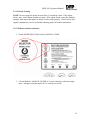
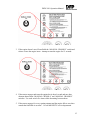
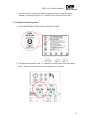
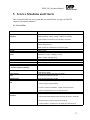
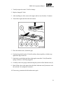
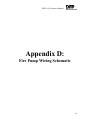
DEUTZ Fire Protection
Engine Operation Manual
DFP4 2011 T10
DFP4 2011 T20
Published by
DEUTZ Corporation
Norcross, GA
Printed in USA
Copyright Notice
© 2007 DEUTZ Corporation
All Rights Reserved
This manual or any of its parts may not be reproduced in any
way without prior written consent from DEUTZ Corporation.
Written by
Adam Riles
Document Number
030-5264
Revision Notice
Revision 1.
Revision History
Revision Level
1
Release Date
Sep-07
Notes
First Release
Table of Contents
1. General……………………………………………………………………………1
1.1. About this Manual…………………………………………………………….1
1.1.1. Notices in this Manual…………………………………………………1
1.2. Deutz Diesel Engines…………………………………………………………1
1.2.1. Care and Maintenance…………………………………………………1
1.2.2. Safety Considerations………………………………………………….1
1.3. Service………………………………………………………………………...2
1.4. Asbestos……………………………………………………………………….2
2. Engine and Fire Pump Unit Description………………………………………..3
2.1. Model………………………………………………………………………….3
2.1.1. Engine Rating Plate…………………………………………………….3
2.1.2. Position of the Engine Rating Plate…………………………………….3
2.1.3. Fire Pump Rating Plate…………………………………………………4
2.1.4. Location of the Fire Pump Rating Plate………………………………..4
2.1.5. Engine Serial Number………………………………………………….5
2.1.6. Cylinder Numbering……………………………………………………5
2.1.7. Fuel Delivery Lock…………………………………………………….5
2.2. Engine Illustrations…………………………………………………………….6
2.2.1. Operation Side……………………………………………………….…6
2.2.2. Exhaust Side……………………………………………………………7
2.3. Oil Circuit………………………………………………………………….…..8
2.3.1. Lube Oil Circuit Schematic………………………………………….…8
2.4. Fuel System Schematic……………………………………………………..….9
2.4.1. Fuel System…………………………………………………………..…9
2.5. Cooling System………………………………………………………………...10
2.5.1. Oil Pan Heater………………………………………………………..…10
3. Engine Operation…………………………………………………………………11
3.1. Commissioning……………………………………………………………….11
3.1.1. Adding Engine Oil…………………………………………………….11
3.1.1.1. Internal Engine Oil Fill-Up………………………………………11
3.1.2. Adding Fuel……………………………………………………………12
3.1.3. Other Preparations……………………………………………………..12
3.1.4. Additional Maintenance Work…………………………………………13
3.2. Starting………………………………………………………………………..13
3.2.1. Electric starting……………………………………………………….. 13
3.2.2. Without Cold Start Assistance…………………………………………14
3.2.3. Manual Solenoid Operation……………………………………………16
3.3. Monitoring Engine Operation…………………………………………………17
3.3.1. Tachometer / Hour Meter………………………………………………17
3.3.2. Oil Pressure Indicator……………………………………………….….18
3.3.3. Coolant Temperature Gage…………………………………………….19
3.3.4. Volt Meter………………………………………………………………19
3.4. Shutting Off the Engine………………………………………………………..20
3.4.1. Electrical Shut-off………………………………………………………20
3.4.2. Mechanical Shut-off…………………………………………………….22
3.5. Operating Conditions…………………………………………………………..23
3.5.1. High Ambient Temperature and Altitude………………………………23
4. Operating Media…………………………………………………………….…….23
4.1. Lube Oil………………………………………………………………………..23
4.1.1. Quality…………………………………………………………………..24
4.1.2. Viscosity………………………………………………………………...24
4.2. Fuel……………………………………………………………………………..25
4.2.1. Quality…………………………………………………………………...25
4.2.2. Winter-Grade Fuel………………………………………………………25
5. Service Schedules and Charts……………………………………………………..27
5.1. Service Plan……………………………………………………………………..27
5.2. Maintenance Chart………………………………………………………………28
5.3. Maintenance Work Completed…………………………………………………29
6. Service and Maintenance…………………………………………………………..29
6.1. Lubrication System……………………………………………………………...29
6.1.1. Checking the Oil Level…………………………………………………..30
6.1.2. Changing the Engine Oil…………………………………………………30
6.1.3. Changing the Oil Filter…………………………………………………..32
6.2. Fuel System…………………………………………………………………….34
6.2.1. Replacing the Fuel Filter………………………………………………..34
6.2.2. Cleaning the Fuel Filter Strainer………………………………………...36
6.3. Belt Drives……………………………………………………………………...37
6.3.1. Belt Cover……………………………………………………………….37
6.3.2. Checking the V-belt……………………………………………………..38
6.3.3. Tensioning the Alternator Belt(s)……………………………………….40
6.3.4. Changing the Alternator Belt(s)…………………………………………40
6.4. Adjustments……………………………………………………………………42
6.4.1. Checking the Valve Clearance………………………………………….42
6.4.2. Adjusting the Valve Clearance…………………………………………43
6.4.2.1. Valve Clearance Adjustment Schematic…………………………..43
6.5. Maintenance of Accessories…………………………………………………...44
6.5.1. Air Cleaner……………………………………………………………...44
6.5.2. Battery…………………………………………………………………..45
6.5.2.1. Checking the Battery and Connectors……………………………...45
6.5.2.2. Checking the Electrolyte Level………………………………….…46
6.5.2.3. Checking the Electrolyte Density……………………………….….47
6.5.3. Alternator…………………………………………………………….….48
6.5.4. Transportation Shackles………………………………………………....48
6.6. Engine Cleaning………………………………………………………………...49
6.6.1. Cleaning the Engine……………………………………………………..49
7. Faults, Causes and Remedies………………………………………………………50
7.1. Fault Tables……………………………………………………………………..50
8. Technical Specifications……………………………………………………………52
8.1. Engine Specifications and Settings……………………………………………..52
8.1.1. Power Curves………………………………………………………….…55
8.2. Oil Volumes……………………………………………………………………..55
8.3. Torque Wrench Settings………………………………………………………...55
9. Tools and Parts……………………………………………………………………..56
9.1. Spare Parts List………………………………………………………………….56
9.2. Tools…………………………………………………………………………….57
10. Service………………………………………………………………………………58
10.1. Knowing It’s DEUTZ………………………………………………………….58
11. Notes………………………………………………………………………………...60
APPENDIX A………………………………………………………………………...…61
Fire Pump Layout Schematic
APPENDIX B…………………………………………………………………………...62
Engine Construction and Materials
APPENDIX C…………………………………………………………………………...63
Fire Pump Connection Map
APPENDIX D…………………………………………………………………………...64
Fire Pump Wiring Schematic
APPENDIX E…………………………………………………………………………...65
Fire Pump Start-up and Installation Check List
DFP4 2011 Operation Manual
1. General
1.1. About this Manual
This manual contains instructions for the DEUTZ DFP4-2011 series engines. Reading
this manual will provide you with information enabling you to avoid accidents, preserve
the manufactures warranty and maintain the engine.
1.1.1. Notices in this Manual
This symbol is used to communicate all safety warnings. Please
follow all warnings in this manual carefully. In addition please
follow all state and federal regulations associated with the use of this
product.
1.2. DEUTZ Diesel Engines
DEUTZ engines are the product of many years of research and development. The
resulting know-how coupled with stringent quality standards, guarantee their long service
life, high reliability and low fuel consumption. As a result, DEUTZ diesel engines meet
the highest standards for environmental protection.
1.2.1. Care and Maintenance
Sound care and maintenance practices will ensure that the engine continues to meet the
requirements placed on it. Recommended service and maintenance intervals must be
observed and carried out.
1.2.2. Safety Considerations
Please abide by the following:
1. Shutdown the engine before carrying out maintenance or repair
work
2. Ensure that the engine cannot be started accidentally
3. Replace any guards or panels that may have been removed
4. Observe industrial safety regulations when running the engine in
an enclosed environment
1
DFP4 2011 Operation Manual
1.3. Service
In the event of a breakdown or for spare part inquiries please contact one of our
authorized service representatives. Our trained specialists will carry out repairs quickly
and professionally using genuine spare parts.
Original parts from DEUTZ AG are always produced in accordance with state-of-the-art
technology. Please turn to the end of this manual for further service information.
1.4. Asbestos
DEUTZ original parts are asbestos-free
2
DFP4 2011 Operation Manual
2. Engine and Fire Pump Unit Description
2.1. Model
Each DEUTZ engine has a Rating Plate that contains information about your engine (see
section 2.1.1. below).
2.1.1. Engine Rating Plate
The DEUTZ rating plate contains performance information and the following:
A. Model Number
B. Engine Serial Number
2.1.2. Position of the Engine Rating Plate
The rating plate C is attached to the valve cover (see below).
3
DFP4 2011 Operation Manual
2.1.3. Fire Pump Rating Plate
The DEUTZ fire pump rating plate contains performance information for your particular
model of fire pump.
2.1.4. Location of the Fire Pump Rating Plate
The fire pump rating plate is located on the rear support leg as shown.
4
DFP4 2011 Operation Manual
2.1.5. Engine Serial Number
The Engine serial number is also stamped on the engine as seen in the drawing below.
2.1.6. Cylinder Numbering
The cylinders are numbered consecutively, beginning at the flywheel.
2.1.7. Fuel Delivery Lock
Adjustments to the governor are to be carried out by authorized DEUTZ
SERVICE specialists only.
The manufacturer shall not be held liable for damages resulting from adjustments made
to the governor by the operator. The lock screws are protected by the following
methods:
1. Locking paint
2. Tamper resistant heads
5
DFP4 2011 Operation Manual
2.2. Engine Illustrations
The purpose of this section is to identify the components of your DEUTZ engine.
2.2.1. Operation Side
1.
2.
3.
4.
5.
6.
7.
8.
9.
10.
11.
12.
13.
14.
15.
Air-intake pipe
V-belt pulley on crankshaft
Narrow V-belt
“Energized to stop” solenoid
Timing belt cover
Manual shut off lever
Speed control lever
Oil fill point (on side of crankcase)
Oil dipstick
Fuel Lift pump with hand primer
Spin-on fuel filter
spin-on oil filter
Injection pumps
Oil cooler connections
Injectors
6
DFP4 2011 Operation Manual
2.2.2. Exhaust Side
16.
17.
18.
19.
20.
21.
22.
23.
Valve cover with built in crankcase ventilation
Exhaust manifold
Flywheel housing
Starter
Crankcase
Turbocharger
Alternator (not shown in actual position)
Intake Manifold
7
DFP4 2011 Operation Manual
2.3. Oil Circuit
The following section contains information regarding the oil circuit of your engine.
2.3.1. Lube Oil Circuit Schematic
1.
2.
3.
4.
5.
6.
7.
8.
9.
10.
11.
12.
13.
14.
15.
16.
17.
18.
19.
20.
Oil pan
Oil-intake pipe
Oil pump
Main oil duct
Oil-cooled cylinders
Cylinder head cooling neck
Oil duct for rocker arm lubrication
Rocker arm
Oil manifold for the thermostat
Outlet to external engine oil cooler
Return from external engine oil cooler
Thermostat housing with slide thermostat
Oil duct to oil filter
Oil filter
Oil duct to cam, con-rod and crankshaft bearings
Spray nozzle for piston cooling
Oil return via crankcase to oil pan
Lube Oil supply to turbocharger
Turbocharger
Return from turbocharger to oil pan
8
DFP4 2011 Operation Manual
2.4. Fuel System Schematic
The following section contains information regarding the fuel system of your engine.
2.4.1. Fuel System
1.
2.
3.
4.
5.
6.
7.
8.
9.
10.
Fuel line from tank to fuel pump
Fuel lift pump (with built in pre-filter)
Fuel line from filter to injection pump
Easy-change fuel filter
Fuel line from fuel lift pump to easy-change fuel filter
Injection pump
Fuel distribution pipe
High pressure injection line
Injectors
Fuel return line to tank
9
DFP4 2011 Operation Manual
2.5. Cooling System
NOTE: Please follow all the maintenance and service procedures outlined in section 6.1
for your engine’s lubrication system.
Engine coolant (i.e. water, Ethylene Glycol, inhibitors etc.) are NOT required
for this engine.
The DFP4-2011 series engines are oil cooled and do NOT require typical water/Glycol
based coolant of any kind. The crankcase lubricating oil is used as the engine coolant.
The oil is cooled by the shell and tube style heat exchanger. As the oil passes through the
shell side it’s cooled by the raw water that is flowing through the tube side. As the oil
exits the heat exchanger it is circulated back through the engine and the process repeats.
The heat exchanger is connected to the engine using hydraulic style hoses. It does not
have any openings nor is an expansion tank required. The oil is drained and filled via the
crankcase. It is not required to drain/change the oil in the heat exchanger during an oil
change. For more information please refer to section 6.1, Lubrication System.
2.5.1. Oil Pan Heater
NOTE: The installation contractor is responsible for connecting the oil pan heater to the
pump AC outlet.
DO NOT drain the oil from the oil pan until the oil pan heater is
disconnected.
DO NOT connect the oil pan heater until the engine is properly filled with oil.
The Deutz DFP4-2011 engines are equipped with an oil pan heater that keeps the oil
warm, which assists with engine cranking. It also helps the engine achieve its maximum
rated horsepower faster.
10
DFP4 2011 Operation Manual
3. Engine Operation
3.1. Commissioning
This section contains information regarding the operation of your engine.
3.1.1. Adding Engine Oil
3.1.1.1. Initial Engine Oil Fill-Up
NOTE: If the person operating the engine does not warm up the engine until the
thermostat opens, the oil level may lie above the “Max” mark on the dipstick when
delivered. The correct level can then only be assessed after the engine has been warmed
up.
Please follow the steps below to add engine oil:
1. Add oil to the engine until the oil level reaches “Max” indicated on the engine
dipstick.
2. In addition, top off the oil quantity in the supply hoses and external oil cooler.
See section 8.2 for quantities.
3. Allow the engine to run warm until the thermostat opens (at approximately 95
degrees C)
11
DFP4 2011 Operation Manual
4. Allow the engine to run for an additional 2 minutes
5. Switch off the engine, wait 5 minutes to allow the oil to drain back to the oil pan.
6. Check the oil level, and if necessary, top off with oil to the “Max” mark on the
dipstick.
3.1.2. Adding Fuel
Use only commercial-grade diesel fuel. For fuel grade, see section 4.2. Use summer or
winter-grade fuel, depending on the ambient temperature.
•
•
•
•
Never fill the tank while the engine is running.
Ensure cleanliness!
Do not spill fuel!
DO NOT use BIO-DIESEL; bio-diesel can cause the fuel
injection components to stick if the engine is not run for an
extended period of time.
3.1.3. Other Preparations
•
•
•
Check battery and cable connectors, (see section 6.7.1)
Remove Transport Shackles, if fitted: (see section 6.7.3)
After all engine preparations have been done conduct a trial run for about 10
minutes with the engine UNLOADED.
12
DFP4 2011 Operation Manual
NOTE: During and after the trial run check for the following:
•
•
•
•
Leaks
Oil level (see section 6.1.2)
Top off with oil; if necessary (see section 3.1.1.)
Re-tension the V-belt (see section 6.5)
3.1.4. Additional Maintenance Work
When commissioning a new or reconditioned engine all of the following MUST be done:
•
•
•
•
•
•
•
Change the lube oil (see sections 6.1.1. & 6.1.2.)
Change the oil filter cartridge (see section 6.1.3.)
Change the fuel filter cartridge (see section 6.2.1.)
Check V-belts and re-tension as needed (see section 6.5)
Check engine for leaks
Check engine mounts, retighten if necessary, (see section 9.2)
Check valve clearance, adjust if necessary, (see sections 5.1 & 6.6.1)
3.2. Starting
This section illustrates the method for starting your engine.
Before starting the engine, be mindful of the warnings below:
When manually starting the engine, make sure that the cooling water
valve is open to the engine’s heat exchanger.
Make sure that nobody is standing in the immediate vicinity of the engine
or driven components.
After any repair work: Check that all guards have been replaced and
that all tools have been removed from the engine.
CAUTION: If the speed governor has been REMOVED, the engine must
NOT be tested under any circumstances.
13
DFP4 2011 Operation Manual
3.2.1. Electric Starting
NOTE: Do not engage the starter for more than 15 seconds at a time. If the engine
doesn’t start, wait a minute and then try again. If the engine doesn’t start after multiple
attempts, then inspect the engine to ensure it’s been setup properly. Please refer to your
engine’s maintenance, service and trouble shooting guides for further information.
3.2.2. Without cold start assistance
1. Put the MODE SELECTOR switch to MANUAL START.
2.
Lift and hold the “MANUAL CRANK A” switch, releasing it when the engine
starts. Attempt to start the engine for 15 seconds (see below).
14
DFP4 2011 Operation Manual
3. If the engine doesn’t start, lift and hold the “MANUAL CRANK B” switch and
release it once the engine starts. Attempt to start the engine for 15 seconds.
4. If the starter engages and turns the engine but it doesn’t crank and run; then
alternate between the “MANUAL CRANK A” and “MANUAL CRANK B”
switches. Use each switch five times while alternating between them.
5. If the starter engages for every starting attempt and the engine fails to run; then
consult the fault table in section 7.1 or call the DEUTZ service department.
15
DFP4 2011 Operation Manual
6. If the starter fails to engage and crank the engine then try starting the engine
manually as outlined in section 3.2.3 entitled “Manual Solenoid Operation”.
3.2.3. Manual Solenoid Operation
1. Put the MODE SELECTOR switch to MANUAL START.
2. Lift and hold the manual crank “A” solenoid lever and release it once the engine
starts. Attempt to start the engine for no longer than 15 seconds.
16
DFP4 2011 Operation Manual
3. If the engine does not start then repeat step 2 above using the manual crank “B”
solenoid lever.
4. If the starter engages and turns the engine but it doesn’t crank and run; then
alternate between the “MANUAL CRANK A” and “MANUAL CRANK B”
solenoid levers. Use each switch five times while alternating between them.
5. If the starter engages for every starting attempt and the engine fails to run; then
consult the fault table in section 7.1 or call the DEUTZ service department.
3.3. Monitoring Engine Operation
This section contains information about monitoring the operation of your DEUTZ engine.
3.3.1. Tachometer / Hour Meter
The tachometer displays the speed at which your engine is running. Built into the
tachometer is a digital display for engine operation hours. This display will only count
up while the engine is running, see below.
17
DFP4 2011 Operation Manual
3.3.2. Oil Pressure Indicator
The pointer must indicate a minimum oil pressure (3.0 bar or 43psi) while the engine is
running.
18
DFP4 2011 Operation Manual
3.3.3. Coolant Temperature Gage
NOTE: The pointer will typically indicate that the engine is operating in the 93-110°C or
200-230°F range. If the indicator displays an abnormally high temperature (above 250°F
or 121°C) then the engine is starting to overheat. If this occurs, shut the engine down and
refer to the fault table in section 7.1.
3.3.4. Volt Meter
The two volt meters, pictured below, monitor the voltage of the primary and secondary
engine battery. While the engine is running the normal voltage should read:
•
13 to 14.5 Volts for a 12V system
•
26 to 28 Volts for a 24V system
19
DFP4 2011 Operation Manual
3.4. Shutting Off the Engine
The information in this section pertains to shutting down your DEUTZ engine.
3.4.1. Electric Shut-Off
NOTE: If possible, do not switch the engine off while fully loaded
If the cooling water manual by-pass valve was opened during manual
starting, make sure it’s CLOSED after shutdown.
If the engine was started with the MODE SELECTION switch in the
AUTOMATIC position, the engine can only be stopped if the switch is in
the AUTOMATIC POSITION; otherwise, engine damage can occur.
20
DFP4 2011 Operation Manual
Please follow the step(s) below to properly shutdown your engine:
1. Return the mode selector switch back to the AUTOMATIC START position.
2. Lift and hold the MANUAL STOP switch until the engine stops.
NOTE: The battery charge light will illuminate when the engine stops.
21
DFP4 2011 Operation Manual
3.4.2. Mechanical Shut-Off
Please follow the step(s) below to properly shutdown your engine:
NOTE: If possible, do not switch the engine off while fully loaded. If this is not
possible, allow it to idle for approximately 2 minutes before shutdown.
1. Return the mode selector switch back to the AUTOMATIC START position
2. Move the shut-off lever 1 until the engine comes to a stop. (NOTE: The charge
battery light will illuminate when the engine stops.)
22
DFP4 2011 Operation Manual
3.5. Operating Conditions
The following information pertains to the operating conditions that your DEUTZ engine
may be in.
3.5.1. High Ambient Temperature and Altitude
As the ambient temperature and/or altitude increases the air density decreases. As a
result, the following engine characteristics will be IMPAIRED:
•
•
•
•
Engine maximum output
Exhaust gas quality
Increased Coolant temperature
Starting behavior (in extreme cases):
The Engine can be used at altitudes up to 91m (300ft) and temperatures up to 25°C
(77°F) without a decrease in performance. If the engine is to be used at higher altitudes
and temperatures then the amount of injected fuel must be REDUCED. This will
DECREASE engine power per NFPA regulations as follows:
•
•
Deduct 1% for each 100m (328 ft) above 91 m (300 ft)
Deduct 1% for each 5.6°C (10°F) above 25°C (77°F)
If you have any doubts about the operation of your engine under these or similar
conditions, ask your equipment supplier. Otherwise please contact DEUTZ SERVICE.
4. Operating Media
The information in this section explains the lube oil and fuel that is used in your DEUTZ
engine.
4.1. Lube Oil
NOTE: Only use 15W40 oil in your DEUTZ engine.
Lube Oils are categorized and rated according to their performance and quality. Oil
specifications are designated by the American Petroleum Institute (API) and the
European Automobile Manufacturers Association (ACEA)
23
DFP4 2011 Operation Manual
4.1.1. Quality
The following are the approved API and ACEA lube oils for your engine:
Approved API Oils:
Minimum: CF-4
Approved ACEA Oils:
Minimum: E1-96
4.1.2. Viscosity
Oil changes that are governed by the seasons can be avoided by using multi-grade lube
oils. Multi-grade oils, particularly light-flowing oils, help reduce fuel consumption.
This engine is equipped with an oil pan heater. Since it is designed and intended to
operate continuously the engine oil will always be warm. Therefore, 15W40 viscosity oil
can be used year round. Otherwise please use the chart below to determine the proper
viscosity of oil that is to be used in your engine.
24
DFP4 2011 Operation Manual
4.2. Fuel
The information in this section refers to the fuel that should be used in your DEUTZ
engine.
4.2.1. Quality
Use commercially available diesel fuel with less than 1.0% sulfur content. Fuels with a
sulfur content greater than 1% are not allowed. The following are the approved fuel
specification / standards to be used with your DEUTZ Fire Protection Engine:
•
•
EN 590: 2004
ASTM D 975-96; 1-D and 2-D
4.2.2. Winter-Grade Fuel
Diesel fuels are never to be mixed with gasoline (petrol)!
Mix in tank only! Fill with the appropriate amount of Kerosene first, and then
add the diesel fuel.
At low temperatures waxing may occur in the fuel system thus reducing engine
efficiency. If the ambient temperature is less than 0°C or 32°F, winter grade fuel
(suitable down to -15°C or 5°F) should be used. This type of fuel is usually available
from filling stations well in advance of the cold months. Diesel fuel containing additives
(Super diesel) is often on sale and for use down to temperatures of -20°C or -4°F.
•
At temperatures below -15°C (5°F) to -20°C (-4°F), Kerosene should be added to
the diesel fuel. The relevant percentages are given in the diagram below.
25
DFP4 2011 Operation Manual
If summer-grade diesel fuel must be used at temperatures below 0°C or 32°F, up to 60%
kerosene can be added. In most cases, adding a flow improver (additive) can be used to
provide the fuel with adequate resistance to the cold temperatures. Please contact
DEUTZ SERVICE for more information regarding fuel additives.
26
DFP4 2011 Operation Manual
5. Service Schedules and Charts
This section describes the service plan that you should follow to keep your DEUTZ
engine in top running condition.
5.1. Service Plan
Item
THE ITEMS BELOW ARE TO BE CHECKED EVERY YEAR
General
Inspection
Check the engine for loose or damaged fittings, clamps, guards
insulating blankets or wiring. Repair or replace as necessary.
Inspect V-belts for looseness or wear and tight connections.
Battery
Engine Oil
Oil Filter
Exhaust
system
Engine Crankcase Breather
Fuel Filter
Fuel Pre-filter Element
Fuel Tank
Cooling Loop Solenoid and
Y-Trap (Not supplied by DEUTZ)
Power Wiring
Engine Control
Panel
Heat Exchanger
Engine Operation
Test
Clean battery terminal posts, check for tight connections and
maintain electrolyte level .
NOTE: Replace as needed but do not exceed 5 years
Replace oil
Replace oil filter
Visually inspect the exhaust system hangers, supports and
flexible pipes for signs of leakage or rusting.
Repair or replace damaged piping.
Clean the engine crankcase breather
Replace the fuel filter
Clean / change pre-filter element
Drain water and sediment from the fuel tank
Check for proper operation
Inspect and clean terminals on the starter, alternator
and the battery isolator.
Inspect the connections and tighten if necessary.
Be careful not to ground any circuits
Inspect the heat exchanger conduits
1. Start the engine: Run the engine for no less than 30 minutes
2. Check for proper gauge readings
3. Check for noises and vibrations. Tighten loose components.
Engine Over-speed Test
Post-operation
Inspection
4. Perform backpressure test on the exhaust system.
Perform over-speed test using the "Over speed" switch
1. Stop the engine
2. Verify that the Mode Selector switch has been returned to "Automatic"
3. Ensure that the fuel tank is at least two-thirds full
4. Check for leaks in coolant hoses, fuel supply and return lines etc.
27
DFP4 2011 Operation Manual
The items below are to be checked every 5 years in addition to the yearly maintenance
schedule.
Item
THE ITEMS BELOW ARE TO BE CHECKED EVERY 5 YEARS
General Inspection
Replace V-belts
Air Filter
Batteries
Fuel Lines
Injectors
Valves Clearance
Cooling System
Replace air filter
Replace batteries
Replace fuel supply and fuel return lines
Check
Adjust if necessary
Clean
5.2. Maintenance Chart
Stop the engine before carrying out any maintenance work.
The maintenance chart shown below is supplied as a self-adhesive label with each engine.
It should be placed where it can be seen clearly on the engine or driven equipment.
Please check to ensure that this is or has been done. If necessary, ask your engine or
equipment supplier for a fresh supply of labels.
NOTE: Routine work should be carried out according to the schedule outlined in section
5.1.
28
DFP4 2011 Operation Manual
5.3. Maintenance Work Completed
Please use the chart below to keep a log of the maintenance that has been done on your
engine.
Op.
Hours
50-150*
125
375
625
875
1125
1375
1625
1875
2115
2375
2625
Date
Signature
Op.
Hours
250
500
750
1000
1250
1500
1750
2000
2250
2500
2750
Date
Signature
* Break-in Service
6. Service and Maintenance
This section describes the different maintenance procedures that are required for your
engine.
6.1. Lubrication System
The following information pertains to the maintenance of your engines’ lubrication
system.
29
DFP4 2011 Operation Manual
6.1.1. Checking the Oil Level
Please follow the steps below to check your engine oil:
1. Switch the engine off
2. Wait 5 minutes for the oil to drain back into the oil pan
3. Remove the oil dipstick
4. Wipe the dipstick with a non-fibrous, clean cloth
5. Insert the dipstick fully and remove again
6. Check the oil level and fill up to “MAX” on the dipstick (if necessary)
a. If the oil level is only just above the “MIN” mark, then more oil must be
added.
NOTE: The Oil level should not be allowed to fall below the “MIN” mark or above the
“Max” mark.
6.1.2. Changing the Engine Oil
Use caution when draining hot oil: Risk of scalding!
Collect the oil in a container. Do not allow the drained oil to run into the soil.
Dispose of the oil in accordance with environmental regulations.
30
DFP4 2011 Operation Manual
To change the oil please follow the steps below:
1. Start the engine
2. Allow the engine to warm up
3. Ensure that the engine or vehicle is level
a. Lube oil temperature should be approximately 80°C (176°F)
4. Switch the engine off
5. Place an oil tray under the engine
6. Unscrew the oil drain plug
7. Drain the oil
31
DFP4 2011 Operation Manual
8. Fit the oil drain plug with a new seal ring and tighten firmly (for torque, see
section 8.2)
9. Pour in fresh lube oil
a. For grade / viscosity information see section 4.1
b. For quantity information see section 8.2
10. Check the oil level, see section 6.1.2
6.1.3. Changing the Oil Filter
Please follow the steps below to change the oil filter:
Risk of scalding!
1. Unscrew the lube oil filter cartridge using a commercial tool and spin it off.
2. Catch any oil that may spill out.
32
DFP4 2011 Operation Manual
3. Clean any dirt from the filter carrier sealing surface
4. Lightly oil the rubber gasket of the new lube oil filter cartridge
5. Manually screw in the new cartridge until the gasket is flush.
6. Tighten the lube oil filter cartridge with another half-turn by hand
7. Check the oil level, see section 6.1.2
8. Check the oil pressure, see section 3.3.1
9. Check the lube oil filter cartridge seal for leaks
33
DFP4 2011 Operation Manual
6.2. Fuel System
The following section provides information about the maintenance of the fuel system.
NOTE: The fuel system does not have to be bled, but there is a manual hand pump built
into the fuel lift pump. This hand pump can be used to prime the system and reduce
starter engagement time.
6.2.1. Replacing the Fuel Filter
Keep open flames away when working on the fuel system.
Do not smoke!
1. Close the fuel shut-off valve
2. Unscrew the fuel filter cartridge using a commercial tool and spin it off.
3. Catch any fuel that may spill out.
34
DFP4 2011 Operation Manual
4. Clean any dirt from the filter carrier sealing surface
5. Apply a light film of oil or diesel fuel to the rubber gasket of new fuel filter
cartridge.
6. Manually screw in the new cartridge until the gasket is flush.
7. Tighten the fuel filter cartridge with another half-turn by hand
8. Open the fuel shut-off valve
9. Check for leaks
35
DFP4 2011 Operation Manual
6.2.2. Cleaning the Fuel Filter Strainer
Keep open flames away when working on the fuel system.
Do not smoke!
Please follow the steps below to properly clean the fuel strainer:
1. Close the fuel shut-off valve
2. Loosen and unscrew the hexagonal nut 1
3. Remove the fuel strainer cover 2 (the cover and strainer are one unit)
4. Clean the fuel strainer 2 with diesel fuel. Replace with a new part if necessary
5. Place seal 3 into position
6. Mount the fuel strainer cover 2
7. Tighten the hexagonal screw 1
8. Check for leaks
36
DFP4 2011 Operation Manual
6.3. Belt Drives
The following section contains information about your engine belts
6.3.1. Belt Cover
DO NOT operate the engine without the Belt Cover secured in place.
The drawing below illustrates the belt cover secured properly in place.
37
DFP4 2011 Operation Manual
6.3.2. Checking the V-belt
Check the tension and change belts with the engine OFF.
Reinstall the belt guard before restarting the engine.
Please follow the steps below to check the V-belt.
NOTE 1: Use a tension gauge to check the belt (see section 8.3)
NOTE 2: After installing new belts, run the engine for 15 minutes and then check the belt
tension again.
38
DFP4 2011 Operation Manual
1. Visually inspect the entire V-belt for damage
2. Replace damaged V-belts
3. After installing new belts, turn on the engine and let it run for about 15 minutes
4. Turn off the engine and check the belt tension
5. Place the indicator arm (1) into the gage
6. Position the guide (3) on the V-belt (2), midway between pulleys, with the stop
against the edge of the belt
7. Push slowly on the black pad (4) at right angles toward the V-belt (2) until the
spring is heard or is felt being triggered.
8. Carefully remove the gauge without altering the position of the indicator arm (1)
9. Read off the value on the gauge where the black indicator arm (1) intersects with
the scale (5). For settings see section 9.1
10. If necessary, pretension the belt and measure again
39
DFP4 2011 Operation Manual
6.3.3. Tensioning the Alternator Belt(s)
Follow these steps to properly tension the engines’ alternator belt:
1. Loosen the bolts labeled (1), (2) and (3) in the above diagram
2. Adjust the alternator labeled (4) in the direction of the arrow by turning bolt (3)
until the correct belt tension is achieved.
3. Then retighten bolts (1), (2) and (3)
6.3.4. Changing the Alternator Belt(s)
Check the tension and change belts only with the engine OFF.
Reinstall the belt guard before running the engine.
40
DFP4 2011 Operation Manual
Please follow the steps below, using the above diagram as a reference, to properly change
the engine’s alternator belt:
1. Loosen bolts (1), (2) and (3)
2. Adjust the alternator (4) in the direction indicated by the arrow by turning bolt (3)
3. Remove and replace the belt
4. Adjust the alternator (4) in the direction of the arrow by turning bolt (3) until the
correct tension is obtained
5. Then retighten bolts (1), (2) and (3)
41
DFP4 2011 Operation Manual
6.4. Adjustments
The following section contains information on adjustments that should be made to your
engine at given service and maintenance periods.
6.4.1. Checking the Valve Clearance
Using the above diagram, please follow the steps below to adjust your engines valve
clearance:
1. Remove the valve cover
2. Position the crankshaft as directed by the schematic in section 6.4.2.1.
3. Before adjusting the valve clearance, allow the engine to cool down for at least 30
minutes. The oil temperature should be below 80 degrees C
4. Check the valve clearance labeled (1) between the rocker arm / tappet contact face
(2) and valve stem (3) with a feeler gage (6) (see diagram below).
NOTE: There should only be a slight amount of resistance when the feeler gage is
inserted. See section 8.1 for the permissible valve clearance.
42
DFP4 2011 Operation Manual
6.4.2. Adjusting the Valve Clearance
Use the above diagram(s) and the steps below to properly adjust the valve clearance.
1. Release locknut (4)
2. Use an Allen key (7) to turn the set screw (5) so that the correct clearance is
attained after locknut (4) has been tightened.
3. Check and adjust the valve clearance on all cylinders.
4. Reinstall the valve cover, with a new gasket, if necessary.
6.4.2.1. Valve Clearance Adjustment Schematic
Crankshaft Position 1:
Turn the crankshaft until both valves in
cylinder 1 overlap (with the exhaust valve
about to close and the inlet valve about to
open). Adjust the clearance of the valves
(marked in black) on the schematic. After
adjusting each rocker arm, mark them with
chalk to indicate that they have been
adjusted.
Crankshaft Position 2:
Turn the crankshaft one full revolution (360
degrees). Then adjust the clearance of the
valves (marked in black) indicated on the
schematic.
43
DFP4 2011 Operation Manual
6.5. Maintenance of Accessories
The following section describes the service and maintenance of your engine’s
accessories.
6.5.1. Air Cleaner
DO NOT attempt to open or disassemble the air filter
NO maintenance of any kind is to be done with the disposable air filter that is supplied
with the engine. The filter is to be removed and a new one installed in its place. Please
see section 9 entitled “Tools and Parts” for the correct part number when ordering a new
air filter.
1. Remove the air filter 1 by loosening the clamp beneath it.
2. Then install the new filter and tighten the clamp to prevent it from becoming
loose.
44
DFP4 2011 Operation Manual
6.5.2. Battery
The following sections describe the service and maintenance of your engines’ battery.
NOTE: 12V units have 2 batteries
24 V units have 4 batteries
Only use 8D size batteries with the engine. For other questions regarding
engine batteries please contact the DEUTZ service department.
6.5.2.1. Checking the Battery and Connectors
Use the above diagram and the steps below to check the battery and its connectors.
1. Keep the battery clean and dry
2. Loosen the clamp bolts and remove them from the battery posts
3. Clean the terminal posts (+ and -) and clamps.
4. Grease the posts with acid-free and acid resistant grease.
5. Place the clamps back onto the posts (ensure good contact with the posts)
6. Tighten the clamp bolts so they are hand tight
45
DFP4 2011 Operation Manual
6.5.2.2. Checking the Electrolyte Level
•
The gases emitted by the battery are explosive! Keep sparks and open
flames away from the battery!
•
Do not allow battery acid to come in contact with skin or clothing!
•
Wear protective goggles!
•
Do not rest tools on the battery!
Please follow the steps below to check the electrolyte level in the battery.
For batteries with testers:
1. Remove the sealing caps (1)
2. Check to see if the electrolyte level reaches the bottom surface of the tester (2)
3. If necessary top off the battery with distilled water
4. Put the tester back into place
5. Screw the sealing caps back into place
46
DFP4 2011 Operation Manual
For batteries without testers:
1. Remove the sealing caps (1)
2. The electrolyte should be 10 to 15mm above the top of the plates
3. If necessary top off the battery with distilled water
4. Screw the sealing caps back into place
6.5.2.3. Checking the Electrolyte Density
•
Measure the density of the electrolyte in each of the cells using a commercial
hydrometer.
•
The hydrometer reading indicates the battery’s state of charge.
•
The temperature of the electrolyte should be +20°C (68°F) when taking the
measurement.
The following chart is used to determine the charge status of the battery based on the
electrolyte density.
Electrolyte Density
in [kg/l]
in [۫Be' (Baume' scale)*
Charge status
Normal
1.28
1.2
Tropical
1.23
1.12
Normal
32
24
Tropical
27
16
well charged
semi-charged, re-charge
1.12
1.08
16
11
dis-charged, immediately charge
* NOTE: The Baume’ scale is out of date and is rarely used today.
47
DFP4 2011 Operation Manual
6.5.3. Alternator
Notes on the three phase system:
•
Never disconnect cables between the battery, alternator and regulator while the
engine is running.
•
However, if it’s necessary to start and operate the engine without a battery then
disconnect the regulator from the alternator before starting.
•
Be sure not to confuse the battery terminals (e.g. positive “+” and negative “-”)
•
Replace a defective charge pilot lamp bulb immediately
•
Cover up the alternator and regulator before washing the engine
•
Do not touch live leads against the frame if you have a motor with a three phase
electrical system.
•
In the case of electric welding, connect the welder grounding cables directly to the
work piece being welded.
6.5.4. Transportation Shackles
Follow the guidelines below to transport your engine safely
Always use the proper lifting tackle (1) when transporting the engine.
48
DFP4 2011 Operation Manual
6.6. Engine Cleaning
The following section contains guidelines for cleaning your engine.
6.6.1. Cleaning the Engine
Turn the engine OFF before cleaning.
Preparation:
1. Switch off the engine
2. Remove the engine covers (replace them after cleaning)
3. Cover the electrical / electronic components and connectors (e.g. alternator,
starter, governor and solenoid)
4. Clean with compressed air to dislodge loose particles
Cleaning with a cold-cleaning solution:
1. Spray the engine with a commercial cold-cleaning solution and allow it to react
for approximately 10 minutes.
2. Spray the engine clean with a strong water jet, repeat if necessary.
3. Allow the engine to run warm so the remaining water can evaporate.
Cleaning with a high-pressure devise:
1. Clean the engine with a jet stream (max spray pressure of 60 bar or 870 psi), max
temperature of 90°C or 194°F).
2. Allow the engine to run warm so that remaining water evaporates.
49
DFP4 2011 Operation Manual
7. Faults, Causes and Remedies
The following section contains information that will help with the diagnoses of common
problems that could occur with your engine.
NOTE:
•
Faults are often caused by the engine not being properly operated or maintained.
•
Each time a fault occurs, check whether all operating and servicing regulations
have been followed.
•
If you cannot find and fix a problem, please contact DEUTZ SERVICE.
7.1. Fault Tables
Use the table(s) on the following page to diagnose and correct common problems that
could occur with your engine.
50
DFP4 2011 Operation Manual
Engine does not start or is difficult to start
Engine starts, but runs irregularly or fails
Engine becomes excessively hot. Temperature warning system responds
Engine output is below normal
Engine does not run on all cylinders
Engine oil pressure is below normal
Engine oil consumption is excessive
Engine smokes:
Blue
White
Black
Cause
●
Engine drive shaft and/or connection to water pump is jammed
●
●
Below starting limit temperature
●
●
Oil level too low
● ●
● ●
Oil level to high
●
●
Incorrect lube oil SAE class or quality
● ●
●
●
Fuel quality not as per operating manual
● ●
● Air cleaner clogged / turbocharger defective
●
● Turbo hose / pipe leaking
●
Cooling water not flowing thru cooler
●
Raw water temperature too high
●
Resistance in cooling system too great / through flow quantity too small
●
Battery defective or discharged
●
Cable connections, starter, electrical circuit loose or oxidized
●
Starter defective or pinion does not engage
● ●
●
●
● Incorrect valve clearance
●
● ●
Incorrect valve leaks
● ●
● ● ●
●
● Injector defective
Recommended Action
Ch
Check
A
Adjust
Rp
Replace
Cl
Clean
T
Top off
Rd
Reduce
Section
Engine Operation
Operating Media
Combustion Air
Cooling System
Electrics
Engine
Ch
Ch
T
Ch
Rp
Rp
Ch / Rp
Ch
Ch / Rp
Ch
Ch
Ch / T
Ch
Ch
A
Ch
Ch / Rp
51
DFP4 2011 Operation Manual
8. Technical Specifications
This section provides technical information about your engine.
8.1. Engine Specifications and Settings
The following section contains technical data for the following engine(s):
•
•
DFP4-2011-T20
DFP4-2011-T10
52
DFP4 2011 Operation Manual
DFP4-2011-T20
General
Physical Data
Cylinders
Cylinder arrangement
4
Length
718 mm
28.3 in
Vertical in-line
Width
553 mm
21.8 in
Bore
94 mm
3.7 in
Height
703 mm
27.7 in
Stroke
112mm
4.4 in
Weight, dry
247kg
543.4 lb
Max bending @ housing
900 Nm
663.3 lb-ft
Cylinder Displacement
0.777 liter
47.4 in³
Total displacement
3.108 liter
189.6 in³
Compression ratio
17.5 : 1
Combustion system
Direct injection
Aspiration
Turbocharged
Fuel System
Lift pump suction head, max
Max force @ flywheel:
Axial
1500 N
337.8 lb
Radial
3700 N
833.3 lb
Certified Gross Power
1.5m
60 in
Engine RPM
1470
1760
2100
2350
2650
2800
14.0 GPH
Kw
38
51
53
54
59
60
61
300 mbar
120 in. H2O
Hp
51
69
71
72
78
81
81
Max restriction in fuel return line
200 mbar
80 in. H2O
Max restriction in fuel pre-filter
200 mbar
80 in. H2O
Lift pump flow @ max rpm
53.1/h
Max restriction in fuel supply line
Fuel filter type
Replaceable cartridge
Combustion Air System
Combustion air flow @ max rating
370.0m³/h
217.7 CFM
Max allowable clean restriction
50 mbar
20 in. H2O
Max allowable dirty restriction
65 mbar
26 in. H2O
Exhaust System
Exhaust gas flow @ max rating
Exhaust temp @ max rating
Max allowable back pressure
965.0 m³/h
3000
Certified Fuel Consumption
g/kw-hr
260
255
231
236
249
253
275
lb/hp-hr
0.427
0.418
0.379
0.388
0.408
0.416
0.452
Liters/hr
11.6
15.4
14.4
15.1
17.0
18.0
19.8
Gal/hr
3.1
4.1
3.8
4.0
4.5
4.8
5.2
m³/h
160
200
265
300
350
390
425
CFM
94
118
156
177
206
230
250
Combustion Air
567.9 CFM
620°C
1148°F
75.0 mbar
30 in. H2O
Exhaust Gas
m³/h
450
550
730
850
970
1075
1170
CFM
265
324
430
500
571
633
689
Cooling System
Type
External oil coolng
Coolant heat rejection % of gross power
Max coolant temp @ engine outlet
140°C
Max coolant operating pressure
7 bar
Lubrication type
Oil flow at max rpm
Oil flow at max rpm
Filter volume
GPM
284°F
60°F
9
9
9
10
13
14
16
101.5 psi
90°F
11
11
11
12
15
16
18
Forced-feed lubrication
40.0 l/min
10.6 GPM
Lubrication System
Lubrication type
Raw Water Flow
Water Temp:
63%
Heat Rejection to Coolant
kW
22.6
30
31.8
33.5
36.6
38
39.5
BTU/min
1285
1705
1809
1904
2080
2161
2247
Forced-feed lubrication
40.0 l/min
10.6 GPM
Certifications
0.4 liter
0.423 qt
U.S. EPA Non Road Tier 2
European COM 2 (37-75kW)
Electrical
Starter motor
Voltage drop, battery (+), max
12V, 2.3kw
24V, 4.0 kw
1.0V
53
DFP4 2011 Operation Manual
DFP4-2011-T10
General
Physical Data
Cylinders
Cylinder arrangement
4
Length
718 mm
28.3 in
Vertical in-line
Width
553 mm
21.8 in
Bore
94 mm
3.7 in
Height
703 mm
27.7 in
Stroke
112mm
4.4 in
Weight, dry
247kg
543.4 lb
Max bending @ housing
900 Nm
663.3 lb-ft
Cylinder Displacement
0.777 liter
47.4 in³
Total displacement
3.108 liter
189.6 in³
Compression ratio
17.5 : 1
Combustion system
Direct injection
Aspiration
Turbocharged
Fuel System
Lift pump suction head, max
Max force @ flywheel:
Axial
1500 N
Radial
3700 N
337.8 lb
833.3 lb
Certified Gross Power
1.5m
60 in
Engine RPM
1760
2100
2350
2650
2800
14.0 GPH
Kw
34
41
45
45
54
54
300 mbar
120 in. H2O
Hp
45
55
60
60
72
72
Max restriction in fuel return line
200 mbar
80 in. H2O
Max restriction in fuel pre-filter
200 mbar
80 in. H2O
Lift pump flow @ max rpm
53.1/h
Max restriction in fuel supply line
Fuel filter type
Replaceable cartridge
Combustion Air System
Combustion air flow @ max rating
370.0m³/h
217.7 CFM
Max allowable clean restriction
50 mbar
20 in. H2O
Max allowable dirty restriction
65 mbar
26 in. H2O
Exhaust System
Exhaust gas flow @ max rating
Exhaust temp @ max rating
Max allowable back pressure
965.0 m³/h
3000
Certified Fuel Consumption
g/kw-hr
255
231
236
249
253
275
lb/hp-hr
0.418
0.379
0.388
0.408
0.416
0.452
Liters/hr
10.1
11.1
12.6
13.1
16.0
17.6
Gal/hr
2.7
2.9
3.3
3.5
4.2
4.7
Combustion Air
m³/h
200
265
300
350
390
425
CFM
118
156
177
206
230
250
567.9 CFM
620°C
1148°F
75.0 mbar
30 in. H2O
Exhaust Gas
m³/h
550
730
850
970
1075
1170
CFM
324
430
500
571
633
689
Cooling System
Type
External oil coolng
Coolant heat rejection % of gross power
Max coolant temp @ engine outlet
140°C
Max coolant operating pressure
7 bar
Lubrication type
Oil flow at max rpm
Oil flow at max rpm
Filter volume
GPM
284°F
60°F
7
7
9
10
13
14
101.5 psi
90°F
9
9
11
12
14
16
34
1935
Forced-feed lubrication
40.0 l/min
10.6 GPM
Lubrication System
Lubrication type
Raw Water Flow
Water Temp:
63%
Heat Rejection to Coolant
kW
19.7
23.5
26
27
33
BTU/min
1120
1337
1479
1536
1877
Forced-feed lubrication
40.0 l/min
10.6 GPM
0.4 liter
0.423 qt
Certifications
U.S. EPA Non Road Tier 2
European COM 2 (37-75kW)
Electrical
Starter motor
Voltage drop, battery (+), max
12V, 2.3kw
24V, 4.0 kw
1.0V
54
DFP4 2011 Operation Manual
8.1.1. Power Curves
8.2. Oil Volumes
Oil Volumes
Initial Fill Volume
Oil Change Volume (with filter)
Liters / Quarts
Liters / Quarts
12 / 12.7
10.4 / 11.0
8.3. Torque Wrench Settings
Please use the chart below to properly tighten the various fasteners on your engine.
Installation location
valve cover
Rocker arm adjustment screw
Mounting Foot
Air Intake Pipe
Exhaust Manifold
Oil drain plug
Oil pan
Injection line attachment
Injection attachment
Lube Oil Filter Cartridge
Fuel Filter Cartridge
Total [Nm]
8.5
21
106
21
22
55
21
30
21
27
27
Comments
TORX
55
DFP4 2011 Operation Manual
9. Tools and Parts
9.1. Spare Parts List
DEUTZ Part #
117-4416
117-4482
134-0488
117-9565
030-0484
118-2151
118-2382
428-7121
118-2153
118-2390
428-7122
428-6257
428-6967
428-1876
428-7258
428-1429
428-6917
030-5299
417-9928
030-3687
030-0482
030-3153
030-XXXX
030-4890
118-2482
118-2876
428-1437
030-0492
030-0477
NA
417-4542
427-2765
417-4821
428-6928
427-0946
Vendor Part #
NA
NA
NA
NA
D065003
NA
NA
NA
NA
NA
NA
Part Description
oil filter
fuel filter with water separator
fuel pre-filter (in fuel lift pump)
v-belt
air filter
12V alternator
12V starter
12V shutdown solenoid
24V alternator
24V starter
24V shutdown solenoid
Fuel Injection System:
NA
a. Injector
NA
b. Injection Pump
NA
c. High Pressure Pipe
NA
d. Fuel Lift Pump
NA
e. Low Pressure Return Pipe
NA
f. Low Pressure Supply Pipe
NA
Stub Shaft
Thermostat
Cooling System:
36631762
a. Oil Cooler Hose (Qty 2x)
b. Water Flex Connector
3500047
c. Oil Pan Heater (120V)
d. Oil Pan Heater (240V)
EKS-518-201503
e. Oil Cooler
NA
Oil Pressure Switch
NA
Oil Temperature Switch
NA
Turbocharger
Speed Control
ESSE-2
Crank Termination / Over Speed Switch
Control Panel & Instruments
Batteries
Governor Spring For Engine Running at:
NA
a. 3000 and 2800 RPM
NA
b. 2650 RPM
NA
c. 2350 RPM
NA
d. 2100 RPM
NA
e. 1760 and 1470 RPM
56
DFP4 2011 Operation Manual
9.2. Tools
TORX
A TORX BN. 8189 screw set is used with engines in the 2011 series. This system was
chosen because of the many advantages it offers:
•
•
•
Outstanding accessibility to bolts
High load transfer when loosening and tightening
Almost impossible for the socket to slide off or break, thereby practically ruling
out the risk of injury.
TORX tools can be ordered from DEUTZ.
V-belt tension gage
The V-belt tension gauge can be obtained under order number 8115 from DEUTZ.
57
DFP4 2011 Operation Manual
10. Service
This section provides information about servicing and parts.
10.1. Knowing it’s DEUTZ
DEUTZ has always stood for excellence in motor construction, pioneering many
developments in the industry. As an independent motor manufacturer, we offer – world
wide – a comprehensive range of diesel and gas motors ranging from 4kW to 7,400kW.
Our products are tailored to meet our customers’ requirements.
Over 1.4 million reliable DEUTZ motors are in use world wide. We are determined to
preserving the high standard of performance and reliability of our motors. DEUTZ is
represented worldwide through a network of service partners who will meet the needs of
our customers, regardless of their location.
This Sales and Service index (pictured below) provides you with an overview of the
DEUTZ partners in your area, including the parts and services that they offer. Your
DEUTZ partner will be happy to help you even when no direct product responsibility is
mentioned.
This index is constantly updated. Please ask your DEUTZ service partner for the latest
edition or visit our website for more information:
On the web at:
http://www.deutz.com
Deutz Corp.
3883 Steve Reynolds Blvd.
Norcross, Ga, 30093
Phone: (770) 564-7100
OR
DEUTZ AG
Ottostrasse 1
D-51149 Koln (Porz)
Entwicklungszentrum
Phone: 0049-221-822-0
Telefax: 0049-221-822-5304
Telex: 8812-0-khd d
DEUTZ AG – at your service.
58
DFP4 2011 Operation Manual
59
DFP4 2011 Operation Manual
11. Notes
Warnings to be placed on equipment:
Warnings in the Manual:
Or
60
DFP4 2011 Operation Manual
Appendix A:
Fire Pump Layout Schematic
61
DFP4 2011 Operation Manual
Appendix B:
Standard Equipment, Engine
Construction and Materials list
62
Item
Description
BASIC CONFIGURATION
MOUNTING
Details
Inline 4 Cylinder, Direct Injection
Type
Pedastal Feet with Rubber Isolators
Cooling and Lubrication
(The lubrication system also serves as the cooling medium)
HEAT EXCHANGER
Type
Oil to water, Shell to tube
Type
Gear Rotor
Drive
Toothed Timming Belt
LUBE OIL FILTER
Type
Spin-on 0.4L
ENGINE HEATER
Type
120V, 150 Watt Immersion Oil pan Heater
LUBRICATION / COOLANT PUMP
Fuel System
Type
Piston
Drive
Type
Engine Camshaft
Unit pump (1 per cylinder)
Drive
Engine Camshaft
INJECTOR
Type
5 Hole Nozzle
AIR CLEANER
Type
Dry Type, Disposable
FUEL FILTER
Type
Spin-on, 0.6L with water separator
FUEL PUMP
INJECTION PUMP
Engine Components
Type
1 Piece Block Type
CYLINDER HEAD
Material
Type
Gray Cast Iron
One Piece - Vertical Inline
Material
Drive
Grey Cast Iron
Toothed Timing Belt and Pulley
Material
Material
Steel with Bimetal Bearings
Nodular Cast Iron
Balance
Integral Counterweights
CYLINDER BLOCK
CAMSHAFT
CRANKSHAFT
Item
Description
Type
Re-entrant Bowl
Details
PISTON
Material
Type
Alluminum Alloy
Standard: 12V, 55 Amp
Optional: 24V, 35 Amp
ALTERNATOR
Drive
Belt Drive
STARTER
Type
Standard: 12V, 2.3kw
FLYWHEEL
Type
SAE 8/10 Industrial Over Center Clutch style
GOVERNOR
Type
Flyweight and Spring
THROTTLE CONTROL
Type
Factory pre-set for required speed and power
Optional: 24V, 4.0 kw
Engine Control Panel and Components
INSTRUMENT PANEL
Type
RUN-STOP CONTROL
Type
OVERSPEED CONTROL
Type
Includes Tachometer, hourmeter, Oil Pressure gage,
Coolant Temp gage, Dual Voltmeters, Overspeed Test and
Reset switches, Dual Start Switches and Shutdown switch,
Charge Indicator Light
Standard: 12V Energized to shutdown solenoid
Optional: 24V Energized to shutdown solenoid
Woodward ESSE-1 with 67% overspeed test and starter
lockout function.
DFP4 2011 Operation Manual
Appendix C:
Fire Pump Connection Map
63
DFP4 2011 Operation Manual
Appendix D:
Fire Pump Wiring Schematic
64
DFP4 2011 Operation Manual
Appendix E:
Fire Pump Manufacturer
And
Installation Contractor
Start-up and Installation
Check Lists
65
DEUTZ FIRE PROTECTION ENGINE / PUMP CHECKLIST
TO BE COMPLETED BY ORIGINAL EQUIPMENT MANUFACTURER OF INSTALLING CONTRACTOR AND
SUBMITTED TO DEUTZ CORPORATION PRIOR TO SCHEDULING START-UP INSPECTION
DEUTZ FIRE PROTECTION
Warranty Department
3883 Steve Reynolds Blvd.
Norcross, GA 30093
Email: [email protected]
Part 1: JOBSITE PROJECT & EQUIPMENT DATA
Facility Name:
Mailing Address:
City:
Postal Code:
State/Region:
Country:
Contact Name:
Phone #:
Fax #:
Email Address:
Jobsite Address:
City:
Postal Code:
State/Region:
Country:
ENGINE INFORMATION
Model:
S/N:
Speed (RPM):
Rating:
OEM MANUFACTURER OF FIRE PUMP PACKAGE
Name:
Model:
Rating(gpm/lpm):
CONTROLLER INFORMATION
Name: (mfr)
S/N:
Pressure: (psi)
Model:
Speed: (RPM)
S/N:
INSTALLATION CONTRACTOR
Name:
Phone #:
City:
Postal Code:
Page 1 of 2
Engine Installation Checklist_Aug 28_2007
DEUTZ FIRE PROTECTION ENGINE / PUMP CHECKLIST
Part 2: CHECKLIST FOR PUMP REPRESENTATIVE OR INSTALLING CONTRACTOR*
Initial
Date
A.) Engine-Pump alignment check; Service coupling/shaft as required.
B.) Unit properly mounted & secured; base grouted.
C.) Controller wiring connected to engine instrument panel.
D.) Batteries serviced and charged 24 hours; connected to engine.
E.) Cooling water connections properly installed on engine heat exchanger,
both inlet and outlet; Confirm cooling water by-pass solenoid operation
F.) Exhaust system properly sized, routed and connected to engine.
G.) Cooling system filled to proper level with DEUTZ approved coolant. **NOT
APPICABLE TO OIL COOLED 2011** (See DEUTZ engine operation manual)
H.) Add DEUTZ approved engine oil to proper level. (see DEUTZ engine operation
manual)
I.) Fuel lines (both supply and return) connected to fuel tank and engine.
J.) Fuel tank filled with clean #2 diesel fuel; drain water & sediment from tank.
K.) Engine jacket water heater connected to correct AC power (after item G) or oil
pan heater on 2011 engines (after item H).
L.) Air inlet filter installed on engine; fresh air supply adequate for engine combustion
and room ventilation.
*These items are to be completed before DEUTZ CORPORATION FIRE PUMP START-UP AND INSTALLATION inspection
START-UP PERFORMED BY:
Company Name:
Mailing Address:
City:
Postal Code:
State/Region:
Country:
Phone #:
Email Address:
Distributor Name:
Individual Performing Start-up:
Date:
Page 2 of 2
Engine Installation Checklist_Aug 28_2007
DEUTZ FIRE PROTECTION START-UP AND INSTALLATION CHECK LIST
RETURN COMPLETED FORM TO:
DEUTZ FIRE PROTECTION
Warranty Administration Department
3883 Steve Reynolds Blvd
Norcross, GA 30093
Contact: 1-800-241-9886
Email: [email protected]
CUSTOMER AND PUMP LOCATION INFORMATION
NAME:
Mailing Address:
City:
Postal Code:
State/Region:
Country:
Contact Name:
Phone #:
Fax #:
Email Address:
Jobsite Address:
City:
Postal Code:
State/Region:
Country:
ENGINE INFORMATION
Model:
S/N:
Speed: (RPM)
Rating:
PUMP INFORMATION
Name: (mfr)
Rating:(gpm):
Model:
S/N:
Pressure: (psi)
Speed: (RPM)
OEM MANUFACTURER OF FIRE PUMP PACKAGE
Name: (mfr)
City:
CONTROLLER INFORMATION
Name: (mfr)
INSTALLATION CONTRACTOR
Name:
State:
Model:
Phone #:
City:
State:
Page 1of 3
Fire Pump Start up_Aug 28_2007
DEUTZ FIRE PROTECTION START-UP AND INSTALLATION CHECK LIST
CHECK LIST
BEFORE ENGINE RUN
Oil level, engine crankcase (see operators manual for
Prime low pressure side, fuel system
Check external bolts, fittings, coupling, etc.
approved oils & volumes)
Coolant level, (see operators manual for approved coolant &
volumes)
Begin hour meter reading (hrs):
Coolant protection, (Not applicable to oil cooled 2011)
Coolant hoses checked for tightness and proper
installation
Check belt tightness
Air intake system, check tightness, etc.
Exhaust System, check tightness, etc.
Fuel supply and return line connections, check
tightness, etc
Fuel tank full, other
What is hose length from fuel tank to engine.
Fuel suction hose diameter:
Fuel return line diameter:
Describe exhaust system
Total length of pipe
Diameter of pipe
Number of elbows 45 o
90o
Exhaust back pressure
inches of HG
Rain protection:
Yes
No
Includes flex pipe and supported by building structure:
Yes
No
Engine block heater connected to dedicated power
supply:
Yes
No
N/A
DURING ENGINE RUN
Check speed, (RPM):
Check for oil leaks; oil pressure (psi):
Check for coolant leaks
Coolant Temperature (oF ):
Coolant loop pressure gauge reading (psi ):
Verify raw water flow (discharge)
Check for external exhaust leaks
Check for fuel leaks
Test High coolant temperature alarm
Test Low oil pressure alarm
Test Over-speed shutdown
Engine gauges functioning properly
AFTER ENGINE RUN
hour meter reading at start of test (hrs):
hour meter reading at end of test (hrs):
Stamp start-up date on upper right corner of engine name plate
Review with customer on who to contact for engine parts and service
Customer acceptance of a maintenance contract Yes
No
Pending
Coolant level full
GENERAL
Room air supply and ventilation equipment complete and adequate. List total dimension of inlet air
opening
Wx
H
List total dimension of discharge air opening
Wx
H
Controller wired per supplier’s instructions, “1” terminal in instrument panel used for cooling water solenoid
Batteries filled, secured and connected:
Cable size:
Total length of battery cable (include pos & neg):
Size of batteries:
Number of batteries:
Page 2of 3
Fire Pump Start up_Aug 28_2007
FIRE PUMP START-UP AND INSTALLATION CHECK LIST (Draft)
START-UP PERFORMED BY:
Company Name:
Mailing Address:
City:
Postal Code:
State/Region:
Country:
Phone #:
Email Address:
Distributor Name:
Individual Performing Start-up:
Date:
GENERAL COMMENTS
Page 3of 3
Fire Pump Start up_Aug 28_2007