1
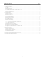
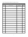
MANUAL
FOR BOILER OPERATION AND INSTALLATION
VIADRUS HERCULES U 24
Updating date 39/2007
Table of contents
page
1. Technical information................................................................................................................................................... 3
1.1 Usage ...................................................................................................................................................................... 3
1.2 Boiler advantages.................................................................................................................................................... 3
1.3 VIADRUS HERCULES U 24 boiler technical date ............................................................................................... 4
1.4 Basic boiler dimensions .......................................................................................................................................... 7
2. Assembly manual.......................................................................................................................................................... 8
2.1 Boiler construction.................................................................................................................................................. 8
2.2 Rules and directives................................................................................................................................................ 9
2.3 Positioning possibilities ........................................................................................................................................ 10
2.4 Delivery and accessories....................................................................................................................................... 11
2.5 Assembly technique.............................................................................................................................................. 11
2.6 Boiler commissioning ........................................................................................................................................... 13
2.6.1 Verification activities before commissioning ................................................................................................ 13
2.6.2 Boiler commissioning .................................................................................................................................... 13
2.7 Regulation and control elements........................................................................................................................... 14
2.8 Equipment for surplus heat withdaral ................................................................................................................... 14
2.9 Equipment for heat withdrawal – accumulation tank ........................................................................................... 15
3. Manual for operation .................................................................................................................................................. 16
3.1 Boiler operation by user........................................................................................................................................ 16
3.2 Boiler cleaning - maintenance .............................................................................................................................. 16
3.3 IMPORTANT NOTICE ....................................................................................................................................... 18
4. Instruction for product disposal after its service life................................................................................................... 19
5. Guarantee and the liability for defects ........................................................................................................................ 19
2
Dear customer,
we thank you that you have bought VIADRUS HERCULES U 24 universal boiler, thus having shown your
confidence in ŽDB GROUP a.s., KKCG Industry Group member, Heating technique division VIADRUS.
For you to get used to a correct way of hadling your new product from the beginning please read at first this
manual for its usage. Please follow the stated information whereby a longlife and trouble-free boiler operation will
be guaranteed for both your and our satisfaction.
1. Technical information
VIADRUS HERCULES U 24 is cast-iron low-pressure boiler designed for combustion of solid fuels – light coal,
hard coal and coke. As a complement fuel it is possible to use wood.
Combustion of other materials, like plastics is impermissible.
1.1 Usage
Three-sectional size of VIADRUS HERCULES U 24 boiler is suitable for heat sources reconstruction in
independent tenements, for smaller residentian premises and leisure amentities. Bigger sizes of boiler (4 – 10 sections)
meet the demands on heating of family houses, shps, schoolds, etc.
The boiler is manufactured as a hot-water boiler with both natural and forced heating water circulation and working
overpressure up to 4 bar. Before dispatch the boiler is tested for tightness by applying 8 bar testing overpressure.
The boiler is designed for heating both closed and open heating systems.
1.2 Boiler advantages
1. Long lifetime of the cast-iron heat exchange and all other parts with regard to the quality of used materials.
2. Long-term verified construction.
3. Sophisticated manufacturing technology on the automatic forming lines with a constant and verified quality of the
manufacturing process (ISO 9001, ISO 14 001).
4. Combustion efficiency 80 %.
5. Easy operation and maintenance.
6. Output graduation according to the sections number.
VIADRUS U 24
Pressure
loss
independence
onprůtoku
pz – Q flow
Závislost tlakové ztráty na
pz-Q
4000
Pressure
Pzp(Pa)
Tlaková loss
ztráta
z (Pa)
3500
3000
10sections
článků
9 sections
článků
8 sections
článků
7 sections
článků
6 sections
článků
5 sections
článků
4 sections
články
3 sections
články
0.2
0.4
2500
2000
1500
1000
500
0
0.0
0.6
0.8
-3
3. -1
FlowPrůtok
rate Q Q (10 m s )
Figure. no. 1 Hydraulic loss of boiler drum
3
1.0
1.2
1.3 VIADRUS HERCULES U 24 boiler technical date
Tab. no. 1 Dimensions, technical parameters – coke as fuel
granularity 24 – 60 mm, fuel moisture max. 15 %
caloric value of fuel: 26 - 30 MJ.kg-1
Number of sections
Nominal heat output
Fuel consumption at the nominal output
Minimum heat output
Fuel consumption at minimum heat output
Combustion chamber volume
Burning tim at the nominal output
Flue gases temperature at nominal heat
output
Flue gases temperature at minimum heat
output
Flue gases mass flow rate at nominal heat
output
Flue gases mass flow rate at minimum heat
output
Efficiency
Boiler class according to EN 303 - 5
Waer space volume
Weight
Combustion chamber depth
Connecting dimensions of smoke flue
Boiler dimensions: height x width
depth L
Filing opening dimensions
Maximum working water overpressure
Minimum working water overpressure
Testing water overpressure
Boiler hydraulic loss
Minimum output water temperature
Control range of water temperature
Noise level
Required chimney draugt
Boiler connections – heating water
– regurn water
Cooling water temperature for safety aftercooling exchanger
Cooling water overpressure for safety aftercooling exchanger
pc
kW
kg/h
kW
kg/h
l
hod
3
16
2,4
4,8
0,72
40,1
4
25
3,75
7,5
1,125
49,9
5
38
5,7
11,4
1,71
59,7
6
46
6,9
13,8
2,07
69,5
7
52
7,8
15,6
2,34
79,3
8
58
8,7
17,4
2,61
89,1
9
66
9,9
19,8
2,97
98,9
10
74
11,1
22,2
3,3
108
4
°C
200 – 280
°C
120 - 190
g/sec
7,55
11,8
17,94
21,71
24,54
27,38
31,15
34,93
g/sec
2,27
3,54
5,38
6,51
7,36
8,21
9,35
10,48
78,7
462
660
88,5
512
770
98
562
880
176
107,8
612
990
%
l
kg
mm
mm
mm
mm
mm
bar
bar
bar
mbar
°C
°C
dB
mbar
“
“
80
3
39,5
262
220
49,3
312
330
59,1
362
440
156
68,9
412
550
1076 x 642
635
766
857
968
245x 195
4
0,5
8
See Fig. no. 1
60
60 – 85
Does not exceed the level 65 dB (A)
0,22
0,25
0,28
0,3
0,32
0,35
6/4
6/4
302
413
0,2
524
°C
5 – 20
bar
2–6
4
1079
0,4
Tab. no. 2 Dimensions, technical parameters – hard coal as fuel
granularity 24 – 60 mm, fuel moisture max. 15 %
Calorific value of fuel: 26 - 28 MJ.kg-1
Number of sections
Nominal heat output
Fuel consumption at the nominal heat output
Minimum heat output
Fuel consumption at minimum heat output
Combustion chamber volume
Burning time at nominal heat output
Flue gases temperature at nominal heat output
Flue gases temperature at minimum heat output
Flue gases mass flow rate at nominal heat output
Flue gases mass flow rate at minimum heat
output
Efficiency
Boiler class according to EN 303 - 5
Water space volume
Weight
Combustion chamber depth
Smoke flue connecting dimesion
Boiler dimensions: height x widht
depth L
Filling opening dimensions
Maximum working water overpressure
Minimum working water overpressure
Testing water overpressure
Boiler hydraulic loss
Minimum output water temperature
Control range of water temperature
Noise level
Required chimney draught
Boiler connections – heating water
– return water
Cooling water temperature for safety aftercooling exchanger
Cooling water temperature for safety aftercooling exchanger
pc
kW
kg/h
kW
kg/h
l
hod
°C
°C
g/sec
3
18
2,93
5,4
0,88
40,1
4
25
4,07
7,5
1,22
49,9
5
32
5,2
9,6
1,56
59,7
2,55
3,54
4,53
7
46
7,48
13,8
2,24
79,3
4
250 – 270
130 – 200
5,52 6,51
g/sec
8,49
11,8
15,1
18,4
%
l
kg
mm
mm
mm
mm
mm
bar
bar
bar
°C
°C
dB
mbar
“
“
39,5
262
220
302
0,15
8
53
8,63
15,9
2,59
89,1
9
60
9,76
18
2,93
98,9
10
67
10,9
20,1
3,27
108
7,5
8,49
9,486
25
28,3
31,62
59,1 68,9
88,5
98
362 412
512
562
440 550
770
880
156
176
1076 x 642
413 524 635
766
857
968
245x 195
4
0,5
8
See. Fig. no. 1
60
60 – 85
Does not exceed the level 65 dB (A)
0,16 0,17 0,20 0,24
0,28
0,32
6/4
6/4
107,8
612
990
49,3
312
330
6
39
6,35
11,7
1,91
69,5
21,71
79
3
78,7
462
660
°C
5 – 20
bar
2–6
5
1079
0,35
Tab. no. 3 Dimensions, technical data – hard coal as fuel
granularity 24 – 60 mm, fuel moisture max. 15 %
calorific value of fuel: 14 – 18 MJ.kg-1
Number of sections
Nominal heat output
Fuel consumption at nominal heat output
Minimum heat output
Fuel consumption at minimum heat output
Combustion chamber volume
Burning time at nominal output
Flue gases temperature at nominal heat
output
Flue gases temperature at minimum heat
output
Flue gases mass flow rate at nominal output
Flue gases mass flow rate at minimum heat
output
Efficiency
Boiler class acccording to EN 303 - 5
Water space volume
Weight
Combustion chamber depth
Smoke flue connecting dimensions
Boiler dimensions: height x width
depth L
Filling opening dimensions
Maximum working water overpressure
Minimum working water overpressure
Testing water overpressure
Boiler hydraulic loass
Minimum output water temperature
Control range of water temperature
Noise level
Required chimney draught
Boiler connections – heating water
– return water
Cooling water temperature for safety aftercooling exchanger
Cooling water overpressure for safety aftercooling exchanger
pc
kW
kg/h
kW
kg/h
l
hod
3
13
3,29
3,9
0,99
40,1
4
19
4,8
5,7
1,44
49,9
5
25
6,33
7,5
1,9
59,7
6
31
7,85
9,3
2,36
69,5
7
37
9,37
11,1
2,81
79,3
8
43
10,89
12,9
3,27
89,1
9
49
12,4
14,7
3,6
98,9
10
55
13,9
16,5
4,18
108
4
°C
220 – 250
°C
110 – 120
g/sec
5,89
8,6
11,33
14,05
16,77
19,48
22,2
24,92
g/sec
1,78
2,58
3,4
4,22
5,03
5,84
6,66
7,48
78,7
462
660
88,5
512
770
98
562
880
176
107,8
612
990
%
l
kg
mm
mm
mm
mm
mm
bar
bar
bar
°C
°C
dB
mbar
78
3
39,5
262
220
49,3
312
330
302
413
0,13
0,14
59,1
362
440
156
68,9
412
550
1076 x 642
635
766
857
968
245x 195
4
0,5
8
See Fig. no. 1
60
60 – 85
Does not exceed the level 65 dB (A)
524
0,15
0,2
0,22
“
“
6/4
6/4
°C
5 – 20
bar
2–6
6
0,28
0,3
1079
0,32
1.4 Basic boiler dimensions
L
L1
D
mm
mm
mm
3
302
4
413
5
524
121
156
6
635
7
766
Fig. no. 2 Basic boiler dimensions
7
8
857
9
968
138
176
10
1079
1
2
3
4
5
6
7
8
upper part of shell
left side part of shell
stoking door
right front part of shell
left front part of shell
draught regulator
ash door
tertiary air rosette
9
10
11
12
13
14
15
tertiary air closure
tilting grate
cleaning cover
right side part of shell
back part of shell
input water pipe
safety overpressure
equipment
16
17
18
19
20
21
boiler drum
smoke adapter
smoke control rod
output water pipe
thermomanometer
combustion space
partition
Fig. no. 3 Basic boiler parts
2. Assembly manual
2.1 Boiler construction
The main boiler part is the cast-iron sectional boiler drum made of the grey cast-iron according to ČSN EN 1561,
quality 150.
The pressure parts meet the strenght demands according to ČSN EN 303- 5 Boilers for central heating – part 5: Solid
fuel boilers for central heating with either manual or automatic supply and maximum nominal heat output 300 kW –
terminology, requirements, testing and marking.
The boiler drum is assembled of sections by means of pressed boiler nipples with 56 mm diameter and secured by
anchor bolts. The boiler sections create the feed space, combustion and ash space, water space and convectional space.
The heating water input and output is situated at the rear boiler part.
There is placed the smoke adapter and heating water connection at the upper part of rear boiler section and the return
water connection at the bottom part. The water connections is possible to connect by means of thread pipes. The stoking
door (possibility of left-right opening the stoking doors see Fig. no. 4), ash door and cleaning cover are connected to the
front boiler section. Under the ash pan door there is installed the tilting grate.
There are placed the combustion space barriers behind the clearing cover. Their quantity differs for each size of
boiler (see Tab. no. 4).
8
The whole boiler drum is insulated by the health harmless mineral insulation, which reduces the losses caused by
heat transmission into the environment. The boiler sell is coloured by a good quality comaxit spray.
Tab. no. 4 Quantity of combustion space barriers
Size of boiler
3 sec. 4 sec. 5 sec.
Single channel barier of
1
combustion space (pc)
Double channel barier of
1
1
combustion chamber (pc)
6 sec.
7 sec.
8 sec.
9 sec.
10 sec.
1
1
-
-
1
1
1
2
2
2
Fig. no. 4 Left-right opening the stoking doors
2.2 Rules and directives
The solid fuel boiler can be installed by the company holding a valid certification for its installation and
maintenance. There must be made lay-out according to the valid rules for the boiler installation. Before the boiler
installation to the older heating system the installation company must make the flush (cleaning) of the whole heating
system. The heating system must be filled with water meeting the requirements ČSN 07 7401: 1992, especially its
hardness must not exceed the required parameters.
Recommended values
hardness
mmol/l
Ca2+
mmol/l
Concentration of whole Fe + Mn
mg/l
*) recommended value
1
0,3
(0,3)*
The producer doesn´t recommend to use the anti-freeze mixture.
a) concerning the heating system
ČSN 06 0310
Central heating, Lay-out and assembly
ČSN 06 0830
Safety equipments for central heating and hot service water preparation
ČSN 07 7401
Water, steam for heating energy equipments with working steam pressure up to 8 MPa
ČSN EN 303–5 Boilers for central heating - Part 5: Central heating solid fuel boiler with manual or automatic
supply, with nominal output not more than 300 kW – terminology, requirements, testing and
marking
b) concerning the chimney
ČSN 73 4201
Chimneys and smoke flue projecting
c) concerning the fire regulations
ČSN 06 1008
Fire safety of heating equipments.
ČSN 73 0823
Fire-technical nature of material. Combustibility grade of building materials.
9
2.3 Positioning possibilities
VIADRUS HERCULES U 24 boiler is approved for installation in non-residential premises (like celars,
corridors, etc.).
Boiler positoning with regard to the fire regulations:
1. The boiler can be installed on a fire-proof floor (Fig. no. 5)
− Place the boiler on fire-proof base exceeding the boiler platform by 20 mm on sides and only up to the boiler drum
depth.
− If the boiler is positioned in a cellar, we recommend to install it on a retaining wall minimum 50 mm hight.
− Install the boiler in the middle of the retaining wall.
2. Safety distance from the combustible materials
− When installing and operating the boiler it is necessary to keep a safety distance 200 mm from combustible
materials with combustibility grade B, C1 a C2 (according to ČSN 06 1008)
− For easily flammable materials with combustibility grade C3, which burn quickly and by themselves, also after the
ignition source removal (like. Paper, millboard, stiff paper, asphalt and tar boards, wood and fireboards, plastics and
flooring materials) the safety distance is doubled, it means to 400 mm
− The safety distance it is necessary to double also in case that the combustibility grade of building material wasn´t
proved.
Quantity of sections
L mm]
3
302
4
413
5
524
6
635
7
766
8
857
9
968
10
1079
Fig. no. 5 Boiler base dimensions
Tab. no. 5 Combustibility grade of building materials and products
Combustibility degrees of
building materials and
products
A – incombustible
B – combustible with difficulty
C1 – hardly combustible
C2 – medium combustible
C3 – easily combustible
Building materials and products ranked in combustibility degrees i
(extract from ČSN 73 0823)
Granite, sandstone, concrete, bricks, ceramic tiles, mortars, fireproof plasters,...
Acumin, izumin, heraklit, lignos, boards and basalt wools, fiberglass boards,...
Beech and oak wood, hobrex boards, plywood, werzalit, formica, sirkolit,...
Pinewood, larch, whitewood, chipboard and cork boards, rubber flooring,...
Asphaltboard, fireboards, cellulos materials, polyurethane, polystyrene, polyethylene, PVC,...
Boiler positioning with regard to the necessary handling space:
− Basic environment AA5/AB5 according to ČSN 33 2000-3
− In front of the boile there must be left a minimum handling area of 1000 mm
− The minimum distance between the rear part of boiler and the wall 400 mm
− At least from one side part keep the acces area to the back boiler part of minimum 400 mm
Fuel positioning:
− It is interdicted to store the fuel behind the boiler or next to the boiler within a distance smaller than 400 mm
10
− It is interdicted to store the fuel between two boilers in the boiler-room.
− The producer recommends to keep the distance between the boiler and fuel min. 1000 mm or to store the fuel in a
different romm that where the boiler is installed.
The selection of the right boiler size
The selection of the right boiler size, it means the heating output, is very important condition for economic operation
and the right boiler function. The boiler must be selected so that the heating output conforms to the heating loss of the
object. The nominal output of the boiler is counted according to the valid rules for outside temperature –12 °C, -15 °C
and –18 °C. The boiler selection with too high heating output (overrating) results in tarring and ratting of boiler. It is not
useful to use the boiler with higher output than the heating loss of the boject.
Chimney draught
The chimney with the right chimney draught is the fundamental prerequisite for the right boiler function. It
influences the boiler output as well as its efficiency. The boiler can be connected to the venting unit with the sufficient
chimney draught, see. Chapter no. 1.3. and if the revision by the certified organization is made.
2.4 Delivery and accessories
VIADRUS HERCULES U 24 boiler is delivered according to the purchase order on the pallet, where the whole
boiler drum is placed and on the sides it is attached the wrapped boiler shell. The accessories are put inside the boiler
drum, accessible by opening the stoking door. The boiler is packed in a transport package and must not be tilted over
during the transport
Standard boiler delivery:
• boiler on a pallete with an adequate number of sections
• boiler shell including the ash pan adequately sized
• cleaning tools (hook, brush with a handle, spike - 2 pcs,
straight threated rivet – 2 pcs)
• thermomanometer (1 pc)
• fillin and discharging cock Js 1/2“ (1 pc)
• complete draught regulator (1 pc) for version 8 - 10
sect. (2 pcs)
• plug Js 6/4“ blind (2 pcs)
•
•
•
•
•
•
•
•
choke screw (1 pc)
spring (1 pc)
joining material for shells
joining material for smoke flap rod
connecting tube 6/4“ (2 pcs)
operating wrench (1 pc)
overpressure safety device (Caleffi type 544)
commercial and technical documentation
2.5 Assembly technique
Boiler drum installation – overpressure safety device
1. Fit the boiler drum on the retaining wall (substruction).
2. Mount to the boiler drum system outlet the connecting tube G 6/4“, connect the second end with heating system.
3. Mount to the boiler drum system outlet the connecting tube G 6/4“ and connect the second end with the heating
system.
4. Connect (according to Fig. no. 9) the overpressure safety device with the return and heating connecting tube and
with the cooling water inlet and with the surplus heat outlet. It is necessary to mount before the overpressure safety
device the filter according to the Fig. no. 10. We recommend that you use 4 pcs of straight screwing with flat sealing
with inner and outer thread to connect the overpressure safety device.
5. Mount the discharging valve to 1/2“ thread in connecting tube of heating water according to Fig. no. 9.
6. Sdet the smoke tube to the smoke adapter and insert it into the chimney. The diameter of smoke tube is 160 mm for
sizes with 3 – 7 sections and pro sizes 8 – 10 sections it is 180 mm.
7. Screw the draught regulator into the opening in upper part of front section. The boiler draught regulator adjustment
procedure is described in the manual enclosed to the particular regulator. For version with 8 – 10 sections there are
used two draft controllers. The second draft controller has to be screwed into the opening in the upper part of the
rear section (Fig. 9).
8. Blind the threated opening JS 6/4“ in the fron section with JS 6/4“ plug. Place the sealing under the plug.
Assembly of shells
1.
2.
Take the shells out of the cardboard cover.
Mount the relevant joining material on the sheet metal components according to Fig. no. 6.
- connecting spindle 13 pc
11
3.
4.
- spring clamp
13 pc
- screw C 4,8 x 13
11 pc
- tang
1 pc
- washer
1 pc
- nut M5
1 pc
Jacket the VIADRUS HERCULES U 24 according to the Fig. no. 6.
Set on the anchor bolts the side parts of shell. Into the upper part of shell insert the thermomanometer and lead the
capillary to the back valve above the insulation of shell upper part and smoke control. It is necessary to keep in
mind that the capilar won´t touch the boiler drum. Screw the back part of shell to its side parts. Finally set on the
front left part of shell and front right part of shell.
1
2
3
4
5
6
7
upper part of shell
left side part of
shell including
insulation
front left part of
shell
front right part of
shell
right side part of
shell
back part of shell
thermomanometer
Fig. no. 6 Boiler shell assembly
Assembly of smoke operation rod
Assembly of smoke operation rod according to Fig. no. 7. Insert the rod into the opening in the upper part of shell
and fix it by use of pin for smoke flap (see Fig. no. 7), set on the washer, spring, washer and fasten down by spring.
Open the stoking door and mount on the upper part of shell.
Note: The opening the stoking door will cause the change of smoke adapter barrier position and the flue gas is
diversed by the shorting opening to the chimney.
1
2
3
4
5
6
7
Fig. no. 7 Assembly of smoke operation rod
12
Smoke adapter
Smoke adapter barrier
Smoke operation rod
Uppera part of shell
Spring pin
Washer
Spring
Cleaning tool assembly
Use the leather gloves and commong assembly tools for assembly or disassembly of the brush and spike point
(if they are included in the delivery).
A change in the direction of opening the stoking door (see Fig. no. 8)
1. To dismount the stoking door by unscrewing the nuts M8.
2. To dismount the shut of stoking door by unscrewing the nuts M8.
3. To secure the shut of stoking door on the place where there was the stoking door mounted on the hinge.
4. Turn the stoking door by 180o. Unscrew the protecting board of stoking door by loosening the nuts M8 and turn it by
180o. Secure the protecting board of stoking door by means of M8 nuts.
5. The latch of stoking door must also be turned by 180o.
6. The stoking door prepared in this way must be secured on the place where there was originally positioned the shut of
stoking door.
1 – Stoking door
2 – Stoking door hinge
3 – Stoking door shut
4 – Nut M8
5 – Washer 8
6 – Protecting board of stoking door incl. insulation
7 – Stud bolt M8 x 25
8 – Elastic straight pin 8 x 30
9 – Latch
Fig. no. 8 Change in direction of opening the stoking door
2.6 Boiler commissioning
This boiler can only be commissioned by a professional assembly firm authorized to do this activity.
2.6.1 Verification activities before commissioning
Before the boiler put into operation it is necessary to check:
a) filling the heating system with water (thermomanometer check) and the system tightness
b) connection to the chimney – this connection can only be done with the agreement of a chimney firm (chimney
revision)
c) draught regulator and thermostatic valve functionality
2.6.2 Boiler commissioning
1.
2.
3.
4.
Fire a boiler
Bring the boiler to the necessary operating temperature. The recommended output water temperature is 80 C.
Adjust the draught regulator including the chain length (according to the enclosed draught regulator manual).
Check the functionality of ovepressure safety device Caleffi.
13
5.
7.
8.
9.
Operate the boiler in the operating condition according to the relevant standards.
Check again the boiler tightness.
Acquaint the user with the operationg and maintenance.
Make a record in the Guarantee certificate.
2.7 Regulation and control elements
The ash pan door choke regulates the combustion air inlet under the boiler grate. It is operated by a draught
regulator or manually by the choke setscrew. The second draught regulator (for 8, 9, 10 sectional versions) regulates the
rear choke. The regulator must be set on the same temperature as the regulator in the front part of boiler.
The stoking door choke serves the secondary air supply into the combustion space.
Tertiary air choke serves the air supply to the combustion channels. Keep it open on 5 mm. for burning the hard and
soft coal.
To check the heating water temperature and water pressure in the heating system there is compound equipment –
thermomanometer. The thermomanometer sensor well is placed in the upper part of front boiler section.
2.8 Equipment for surplus heat withdaral
The overpressure safety device serves as surplus heat withdrawal in case that the maximum water
temperature 95 C is exceeded.
In case that the boiler is overheated (the output water temperature is higher than 95 C) and the system is equipped
with the overpressure safety device, the overpressure safety device creates the cold water circuit which is maintained
until the temperature has dropped below the limit value. At this moment both discharging cooling device and the cold
water inlet supplied to the system close up.
1 – overpressure
safety device
Caleffi type 544
2 – cooling water
inlet 1/2“
3 – overpressure
safety device
sensor
4 – heating water
outlet
5 – heating water
inlet
6 – surplus heat
outles 1/2“
Fig. no. 9 Connectiong scheme for overpressure safety device
Technical data of the pressure relief device (Caleffi valve, type 544)
Switch-on temperature:
Switch-off temperature:
Maximum temperature:
Maximum pressure on the boiler side:
Maximum pressure on the water refilling side:
Max. discharge flow UP 1 bar:
Threads mating dimension:
Probe thread:
Probe capillary length:
100 °C (+0° - 5 °C)
60 °C
110 °C
6 bar
6 bar
1800 kg/h
1/2“ with inside thread
1/2“ with external thread
1300 mm
Installation
The pressure relief device can be installed in any position. The connection of distributions to the pressure relief
device incl. the filter connection must be sealed with the supplied siseal sealing cement. The probe is mounted at the
outlet into the heating water flange. Refilling of the system must be connected directly to the water main. It is
recommended to use the closing valves at heating water inlet and outlet.
14
Important
It is impossible to reverse the flows therefore it is necessary to follow the indication of filling and discharging on the
valve.
1
1 – overpressure safety device sensor
2 – heating water outlet
3 – overpressure safety device Calleffi 544
4 – surplus heat outlet
5 – return water inl
6 – cooling water inlet
7 – filter
2
3
7
4
5
6
7
Fig. no. 10 Hydraulic diagram of pressure relief device connection
In case of using an open expansion tank it is not necessary to use a pressure relief device against overheating.
Every heat source in an open heat system must be connected with an open expansion tank positioned at the highest
point of the heat system. The expansion tanks must be rated in the way that they can contain the changes in water
volume resulting from heating and cooling.
The open expansion tanks must be equipped with non-closable bleeder and a overflow pipes. The overflow pipe
must be designed in the way that it safely drains off the maximum flow volume entering the system. This can be
achieved by rating the overflow pipes by one DN higher than that of the filling piping. The expansion tanks and their
connecting pipes must be designed and positioned in the way that freezing is reliably inhibited.
1
2
3
4
5
6
7
8
Heat source
Expansion tank
Safety piping
Expansion piping
Overflow piping
Filling piping
Water level limiter
Reverse piping
Fig. no. 11 The examples of open expansion tanks connection
2.9 Equipment for heat withdrawal – accumulation tank
In case that the required volume of heating system exceeds 300 l, we recommend to install the accumulation tank.
The calculation of the minimum volume of stack heat exchanger:
where:
Vsp
accumulation tank volume in l
Vsp = 15Tb x QN (1-0,3 x (QH/Qmin)
15
QN
Tb
QH
Qmin
nominal heat output in kW
burning time in hours
thermal load of buildings in kW
the minimum heat output in kW
The dimensions of accumulation tanks for central heating boilers that are operated with individual prescribed fuels,
must be set according to the output, which needs the biggest accumulation tank. This type of accumulation tank isn´t
necessary in case that the calculated volume doesn´t exceed 300 l.
3. Manual for operation
3.1 Boiler operation by user
COKE
The most suitable fuel is coke of 24 – 60 granularity
Burning time at the nominal output is 4 hours.
SOFT COAL
The most suitable fuel is sort coal with 24-60 mm
granularity.
Burning time at nominal output is 4 hours.
HARD COAL
The most suitable fuel is hard coal of 24 – 60 mm
granularity. Burning time at nominal output is 4 hours.
ADDITIONAL FUEL – WOOD
Using this fuel it is not reached the nominal output.
Firing
1.
2.
3.
4.
5.
6.
7.
8.
Check the water volume in the heating system on thermomanometer.
Open the closing fittings between the boiler and the heating system.
Clean the grate and ash-pan.
Insert the kindling and wood trough the ash door on the cleaned grate all over its depth.
Light the kindling throught the ash door.
Close the ash door and opet fully the choke. For 8 – 10 sectional version open the rear choke too.
Put the basic fuel bed on the burning wood.
After its good burning put another fuel up to the lower edge of stoking door and balance the fuel to the equal levels
on all the depth of the boiler.
Operation
1.
2.
3.
4.
5.
6.
7.
After having achieved the heating water temperature regulate the combustion air inlet. The boiler output is
regulated by choke, which regulates the secondary air inlet under the grate either manually or by use of the draught
regulator. Adjust the regulator so that the ash door choke is nearly closed ath the moment of achieving the required
heating water temperature.
According to the heat requirement and according to the burning intensity it is necessary to refill the boler by fuel
during the boiler operation. Stoke in the way making sure that the fuel layer is equally high along the whole depth
of the boiler.
When using coke, hard coal and soft coal it is necessary to open partially the stoking door choke for a primary air
inlet. The teriary air inlet choke must be opened at 5 mm.
To switch-over to the night inhibition regime clean the grate and let the newly stoked fuel well burn. Close the ash
door choke. The stoking door choke must be always open. The draught regulator can be disconnected in this case
(close the choke totally).
The morning re-putting into operation make by opening the ash door choke, together with poking up the grate after
the ash door opening.
The ash door must be closed during the boiler operation.
If necessary, clean the ash pan (the gloves needed).
3.2 Boiler cleaning - maintenance
1.
2.
Remove the ash from the ash-pan during the boiler operation even several times a day according the the fuel type,
because the full ashpan inhibits the correct combustion air allocation under the fuel and causes the unequal fuel
burning on a grate. All the rests in heating chamber, specially the cinder, do remove before every new firing and at
the morning re-putting into boiler operation. The ash must be placed into the non-flammable container with cover.
Use the protecting aids and be personal safety minded during the work.
At burning coke, hard coal and soft coal clean monthly by the help of boiler brush the walls of the boiler inside the
hopper, smoke adapet (Fig. no. 12), space for tertiary air inlet (unscrew the closing plate – Fig. no. 13).
16
1 – Screw with hexagonal head M5 x 14
2 – Washer 5
3 – Cleaning cover of smoke adapter
4 – Smoke adapter cleaning cover insulation
Fig. no. 12 Smoke adapter cleaning
1 – Screw with hexagonal head M8 x 35
2 – Rosette
3 – Screw with cylindrical head M6 x 16
4 – Closing plate
Fig. no. 13 Closing plate dismounting
3.
4.
5.
After finishing the heating season it is necessary to clean the smoke flues of the boiler. Unscrew the cleaning cover,
take out the combustion space barriers, clean the smoke flues by use of the appropriate cleaning tools (Fig. no. 14).
After cleaning insert the combustion space barriers back so that the rear part of boiler stays open and screw down
the cleaning cover.
If there settles tarry lodgement on the combustion space walls while using the fuels with higher evolution of
gas,remove it by use of scrape or the dry bigger piece of wood (eventually coke) when putting the boiler into
operation on max. working temperature
After the heating season finishing service the taps of the smoke flap and all doors.
17
1 – Screw M4 x 5
2 – Draught regulator plug
with chain
3 – Front left and right part of
shell incl. insulation
4 – Stoking door
5 – Door tap
6 – Nut M8
7 – Washer Ø 8
8 – Stoking door hinge
9 – Nut M8
10 – Washer Ø 8
11 – Cleaning cover
12 – Combustion space
barrier
Fig. no. 14 Cleaning cover dismounting
3.3 IMPORTANT NOTICE
1. The boiler can be operated only by adult persons acquainted with this operation manual. It is inadmissible to
leave the children unattended by adults near the boiler. The boiler construction invervention, which can
endanger the attendant´s safety, eventually the housemate´s safety, is inadmissible.
2. If there occurs a danger or flammable vapours and gases development and penetration into the boiler room,
or at works accompanied by the temporary development of the fire or explosion (gluing the floor covering,
painting with combustible painting colours), the boiler must be duly closed down before the works start.
3. It is FORBIDDEN to use the flammable liquids for VIADRUS HERCULES U 24 boiler firing.
4. It is FORBIDDEN to overheat the boiler during its operation. Fill the boiler under the lower edge of stoking
door. Open the stoking door by use of plastic handle and half-open the ash door to smoke vent the smoke
gases.
5. It is forbidden to put the flammable materials on the boiler or in its near distance.
6. When cleaning the ashes at VIADRUS HERCULES U 24 boiler there must not be put any flammable
materials within minimally 1500 mm distance from the boiler.
7. When operating the boiler at the temperature lower than 60 C the boiler drum can be bedewed, which means
the low-temperature corrosion and reduction of boiler drum service life. Therefore we recommend to operate
the boiler at the temperature of 60 C and higher.
8. After the heating season termination it is necessary to clean the boiler, smoke-flues and smoke adapter
properly. Spread the graphitic grease on swivel taps, smoke flap mechanism and on other flexible parts of
boiler. Keep the boiler room clean and dry.
9. Possible corrosion marks on boiler drum don´t mean a defect and they don´t affect the boiler function.
The list of contractual service organizations is attached separately.
18
4. Instruction for product disposal after its service life
ŽDB GROUP a.s., KKCG Industry Group member is a contracting partner of the firm EKO–KOM a.s. with the
client number EK–F00060715.
The packages comply with ČSN EN 13427.
We recommend to dispose the packages in the following way:
plastic foil, cardboard cover, use a salvage point
metal strapping tape, use a salvage point
wooden base, is designated for a single usage and no longer can be used as a product. Its disposal is subject to
Act. 94/ 2004 Sb. a 185/2001 Coll.as amended.
Whereas the boiler is constructed from common metal materials, we recommend to dispose the individual parts as
follows:
the heat exchanger (grey cast-iron), use a junk
distribution pipes, shells, use a junk.
other metal parts, use a junk
insulation material ROTAFLEX, through a firm engaged in waste collection and disposal.
In case that the product has lost its serviceability, you can use the back collection service (if this is introduced). If
the originator has declared that it is the waste and it will be handled according to the legislative provisions valid
in the particular country.
5. Guarantee and the liability for defects
ŽDB GROUP a.s., KKCG Industry Group member, heating technique division VIADRUS provides the
guarantee:
– For boilers 24 months after the boiler putting into operation, but maximum 30 months after the date it was
dispatched from the manufacturing factory.
– For boiler drum 5 years after the date its dispatch from the manufacturing factory.
In case of possible complaint of boiler shell, the customer is obliged to sumit the packing label of the boiler shell.
It is placed on the cardboard, in which the shell has been dispatched.
The user is obliged to entrust the commissioning to the professional assembly firm and a fault rectification
to a contractual service accredited by the ŽDB GROUP a.s., KKCG Industry Group member, heating technique
division VIADRUS, otherwise the guarantee for a boiler proper fnction does not apply.
“VIADRUS HERCULES U24 boiler quality and completeness certificate” serves after its filling as
a “Guarantee certificate
A regular boiler maintenance must be done by its user.
Every notification of fault must be conveyed immediately after its detection, always in writing or via the
telephonic advice.
If the above instructions are not observed, the guarantee provided by the manufacturer will not be recognized.
The manufacturer reserves the right to make modifications within the product innovations, that needn´t be
included in this manual.
The guarantee doesn´t apply to:
- the faults caused by a wrong assembly (see chapter 2.5) or wrong product operation (see chapter 3.1) and faults
cause y wrong maintenance (see chapter 3.2).
- Product damage arisen during the transport or other mechanical demage
- Faults cause by rought storage
- Faults caused by the failure to observe the water quality in the heating system, see chapter 2.2.
- Faults caused by the failure to observe the instructions stated in this manual.
19
Information for customer
Packaging edentification
Assessment reference
PE Plastic sacks, folie, corrugaled board, iron and plastic fix line
Identification od principál materials used. Paper, Polyethylene, iron, wood
Part 1: Summary of assessment
Standard/Report
Assessment requirement
1.1 Prevention by source
reduction
ensure below maximum permitted levels for
1.2 Heavy metals and
components
(CR 13695-1:2000)
1.3 Other noxious/hazardous ensure in compliance with
(CR 13695-2:2002, EN 13428:2000)
substances
ensure reusability in all terms of the
2 Reuse
standard for the functional packaging unit
(EN 13429:2000)
ensure recyclability in all term sof the
3.1 Recovery by material
standard for the functional packaging unit
recycling
(EN 13430:2000)
ensure that calorific gain is achievable for
3.2 Recovery in the form of
the functional packaging unit
energy
(EN 13431:2000)
ensure compost ability in all terms of the
3.3 Recovery by composting standard for the functional packaging unit
(EN 13432:2000)
Claim
Note
YES
YES
YES
NO
YES
YES
Iron - NO
NO
NOTE Conformity with EN 13427 requires affirmative responses to sections 1.1; 1.2; 1.3 and to at least one of
3.1; 3.2; 3.3. In addition, where a claim of reuse is made section 2 should also record affirmative
responses.
Part 2: Statement of conformity
In the light of the assessment results recorded in part I above, this packaging is claimed to comply with the
requirements of EN 13427:2000.
20
Intended for user
ŽDB GROUP a.s. KKCG Industry Group member
závod Topenářská technika VIADRUS
Bezručova 300
735 93 Bohumín
Guarantee certificate and Quality and completeness certificate
VIADRUS HERCULES U 24
Boiler serial number
..............................……….
Boiler output
.....................................
User (Surname, name)
…………………………………………………………………………………………
Adress (street, town, postcode)
…………………………………………………………………………………………
Telephone/Fax
…………………………………………………………………………………………
Boiler complies with requirements
ČSN EN 303-5
Boilers for central heating – Part 5: Solid fuels boilers for central heating, with manual or
automatic supply, with max. 300 kW nominal heat output – Terminology, requirements,
testing and marking.
Adjustment according to the operation and installation manual will be carried out by a contracting service organization.
The guarantee certificate isn’t valid without having been filled in.
The user declares that: the boiler boiler adjusted by the qualified assembly firm didn´t show out any fault during the
testing:
• Received the “Operation and installation manual” with properly filled Guaratee certificate and Quality certificate
• Has beed acquainted with the boiler operation and maintenance
……………………………………..
Date of production
……………………………………..
Manufacturer´s stamp
……………………………………..
Checked by (signature)
……………………………………..
Installation date
……………………………………...
Assembly firm
(stamp, signature)
……………………………………..
User´s signature
…………………………………….
Boiler commissioning date
……………………………………..
Contracting service organization
(signature, stamp)
……………………………………..
User´s signature
21
22
Intended for service organization
ŽDB GROUP a.s. KKCG Industry Group member
závod Topenářská technika VIADRUS
Bezručova 300
735 93 Bohumín
Guarantee certificate and Quality and completeness certificate
VIADRUS HERCULES U 24
Boiler serial number
..............................……….
Boiler output
.....................................
User (Surname, name)
…………………………………………………………………………………………
Adress (street, town, postcode)
…………………………………………………………………………………………
Telephone/Fax
…………………………………………………………………………………………
Boiler complies with requirements
ČSN EN 303-5
Boilers for central heating – Part 5: Solid fuels boilers for central heating, with manual or
automatic supply, with max. 300 kW nominal heat output – Terminology, requirements,
testing and marking.
Adjustment according to the operation and installation manual will be carried out by a contracting service organization.
The guarantee certificate isn’t valid without having been filled in.
The user declares that: the boiler boiler adjusted by the qualified assembly firm didn´t show out any fault during the
testing:
• Received the “Operation and installation manual” with properly filled Guaratee certificate and Quality certificate
• Has beed acquainted with the boiler operation and maintenance
……………………………………..
Date of production
……………………………………..
Manufacturer´s stamp
……………………………………..
Checked by (signature)
……………………………………..
Installation date
……………………………………...
Assembly firm
(stamp, signature)
……………………………………..
User´s signature
…………………………………….
Boiler commissioning date
……………………………………..
Contracting service organization
(signature, stamp)
……………………………………..
User´s signature
23
24
Intended for manufacturer
ŽDB GROUP a.s. KKCG Industry Group member
závod Topenářská technika VIADRUS
Bezručova 300
735 93 Bohumín
Guarantee certificate and Quality and completeness certificate
VIADRUS HERCULES U 24
Boiler serial number
..............................……….
Boiler output
.....................................
User (Surname, name)
…………………………………………………………………………………………
Adress (street, town, postcode)
…………………………………………………………………………………………
Telephone/Fax
…………………………………………………………………………………………
Boiler complies with requirements
ČSN EN 303-5
Boilers for central heating – Part 5: Solid fuels boilers for central heating, with manual or
automatic supply, with max. 300 kW nominal heat output – Terminology, requirements,
testing and marking.
Adjustment according to the operation and installation manual will be carried out by a contracting service organization.
The guarantee certificate isn’t valid without having been filled in.
The user declares that: the boiler boiler adjusted by the qualified assembly firm didn´t show out any fault during the
testing:
• Received the “Operation and installation manual” with properly filled Guaratee certificate and Quality certificate
• Has beed acquainted with the boiler operation and maintenance
……………………………………..
Date of production
……………………………………..
Manufacturer´s stamp
……………………………………..
Checked by (signature)
……………………………………..
Installation date
……………………………………...
Assembly firm
(stamp, signature)
……………………………………..
User´s signature
…………………………………….
Boiler commissioning date
……………………………………..
Contracting service organization
(signature, stamp)
……………………………………..
User´s signature
25
26
Annex to the guarantee certificate for customer- the user
Record of accomplished guarantee and post-guarantee repairs and regular product checks
Record
date
Contracting service
organization
(stamp, signature)
Carried out activity
27
Customer´s
signature
ŽDB GROUP a. s., člen KKCG Industry,
závod Topenářská technika VIADRUS
Bezručova 300, 735 93 Bohumín
tel.: +420 596 083 050, fax: +420 596 082 808, 596 082 822
28