1
IntraStack 6014DSB
2
Install Expansion units (if any)
Up to two expansion units can be added to the IntraStack 6014DSB, allowing up to 4
connections in a single, logical stack.
Initial expansion units for the IntraStack 6014DSB include the following:
•
•
IntraStack 6016DSE — 16 port, 10/100TX expansion unit
IntraStack 6008FXE — 8 port, 100Base-FX fiber expansion unit
To install an expansion unit, refer to "Installing Expansion Units" in Chapter 2 of the
IntraStack 6014DSB's User's Manual.
3
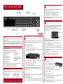
Install MII Expansion Modules (if any)
The IntraStack's two optional Media Independent Interface (MII) expansion slots on
the switch's front panel allow for the addition of various types of media access
modules, including: 10/100TX, 100Base-FX and 10Base-FL.
The MII expansion modules are sold separately and comply with IEEE 802.1 and
802.1u specifications.
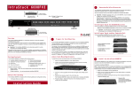
IntraStack Front Panel
MII Opening Brack
Overview
This guide provides instructions for mounting, installing, and configuring your IntraStack
6014DSB Ethernet switch.
This guide assumes you are familiar with installing and managing Ethernet switches. If
you are not familiar with installing and managing Ethernet switches, refer to the IntraStack
6014DSB User's Manual included in your package for more detailed instructions.
1
The IntraStack can be installed in a standard 19-inch equipment rack. It can also be
placed on a horizontal surface with support capabilities of 12 pounds (5.4 kilograms).
To install the IntraStack in an equipment rack:
2. Remove an MII cover bracket from the front of one of the MII expansion slots.
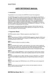
2. Locate a rack-mounting bracket (supplied) and place it over the mounting holes
on one side of the unit, as shown below.
The IntraStack 6014DSB is shipped with the following items:
(1) User's Manual
7. Tighten the thumbscrew on the MII opening bracket's cover.
(1) Quick Installation Guide (this card)
(1) IntraStack Web Browser Management
Manual Addendum
(1) Registration card
4
3. Insert six screws (supplied) into the holes and tighten with a Phillips screwdriver.
4. Repeat the two previous steps for the unit's other side.
•
Network cables — refer to Step #5 ("Connect to the Network") to determine the
cables you need to connect the IntraStack to the network.
•
Phillips screwdriver — for rack-mounting the IntraStack.
5. Place the IntraStack in an equipment rack.
6. Secure the IntraStack by screwing its mounting brackets to the equipment rack.
▲
Default Settings
Important: Make sure the switch is supported until it is secured to the equipment
rack. Failure to do so could cause the switch to fall, resulting in personal injury or
damage to the unit, or both.
The IntraStack 6014DSB is shipped with the following default configuration settings:
IP address: 0.0.0.0
Subnet mask: 0.0.0.0
Default gateway: 0.0.0.0
•
•
•
4. Slide the MII module into the slot until it stops, then push the module in until it se
with the connector.
6. Place the MII opening bracket over the MII expansion slots.
Additional materials required:
•
•
•
3. Align the bottom of an MII module with the rails on the inside of the expansion sl
5. Repeat steps 2 - 4 to install another MII expansion module.
(1) MII opening bracket
(2) MII cover brackets
(2) Rack-mounting brackets
(16) Standard Phillips screws
The MII expansion modules are hot-swappable; you can install and or/remove a
module without turning the switch's power off.
Equipment Rack Installation
1. Place the IntraStack on a flat, stable surface.
IntraStack 6014DSB Ethernet switch
Goldcard™ connector
Power cord
Stack-mounting pins
To install an MII module:
1. Remove the MII opening bracket from the front of the MII expansion slots by
unscrewing the bracket's thumbscrew.
Package Contents
(1)
(1)
(1)
(2)
Rack Mount or Prepare for Desktop Placement
Auto-negotiation: enabled
Spanning Tree: enabled
Switching mode: store-and-forward
Quick Installation Guide
Connect Power Cord
To connect the IntraStack's power cord:
1. Plug one end of the supplied power cord into
the connector on the unit's rear panel.
2. Plug the other end into a grounded AC outlet.
3. Turn the power switch to the "on" position.
The front-panel LEDs blink and the power light illuminates and remains on.
4. Turn the switch's power off.
Desktop Placement
The IntraStack has four rubber feet on the bottom of the chassis that enable desktop/
free-standing installation of the unit.
For free-standing/desktop placement:
1. Place the IntraStack on a flat, stable, horizontal surface with a minimum area of
17.1" x 13.5" (434.3 mm x 342.9 mm) and support capabilities of 12 lbs. (5 kg.).
IntraStack Power Sequence
The following power-on sequence must be followed when an expansion unit is installe
1. Power on the expansion unit(s) first.
2. Power on the IntraStack 6014DSB last.
The following power-off sequence must be followed when an expansion unit is install
1. Power off the expansion unit(s) first.
5
Connect to the Network
To connect the IntraStack to an Ethernet network:
1. Make sure the IntraStack is not powered on.
6
Configure for Management
LED Indicators
To use the IntraStack 6014DSB as a managed switch, it must be configured with an IP
address. This can be accomplished in one of two ways:
2. Connect network devices to the switch, following the cable guidelines below.
3. Power on the IntraStack.
•
automatically using BootP (default)
•
manually via the Console port
BootP Configuration
The IntraStack 6014DSB is shipped with BootP/TFTP support. BootP allows the
switch to be automatically configured with an IP address when the switch is connected to the network and is powered on, if your network contains a BootP server
configured with available, valid IP addresses.
1.
Make sure your network has a BootP server configured with a valid IP address
entry for the IntraStack.
2.
When the IntraStack is connected to the network and is first powered on, it
automatically transmits a BootP request across the network (up to 10 times) until it
receives a valid IP address from the BootP server.
3.
After an IP address is received, the switch can be managed via in-band access.
Refer to Chapter 4 in the IntraStack 6014DSB User's Manual for more information.
If an IP address is NOT received, the switch will need to be manually configured
with an IP address via the Console port. See "Console Configuration" below.
10/100 Port cabling procedures
▲ Important: The IntraStack 6014DSB must be located within 100 meters of its
attached 10Base-T or 100Base-TX devices.
Console Configuration
1.
2.
Using an RS-232 cable, connect a stand-alone terminal or a PC with a terminal
emulator to the Console port on the IntraStack.
Make sure both units are powered on.
If using a PC with a terminal emulator, make sure it is configured with the
following terminal settings:
• Bits Per Second: 9600
• Data Bits: 8
• Parity: None
• Stop Bits: 1
• Flow Control Hardware: None
▲
Important: For information on using the front panel LEDs to troubleshoot problems with your network or the IntraStack, see Appendix A, "Troubleshooting," in the
IntraStack 6014DSB User's Manual.
Technical Specifications
Network Management
SNMP-compatible management software, HTTP management software,
Telnet software
Connectors
RS-232 (DB-9), RJ-45, MII (Media Independent Interface)
Spanning Tree Support
IEEE 802.1d
MII 10/100TX Expansion Port Cabling Procedures
MAC Address Table Size 8000
3.
After connecting the terminal to the switch, the Local Management Interface Main
Menu appears on the screen.
4.
Type c to open the Configuration Menu.
The "Enter Password" prompt appears.
5.
Type Asante at the "Enter Password" prompt.
The password is case-sensitive; enter it exactly as shown.
MII 100Base-FX Expansion Port Cabling Procedures
6.
Press return.
The Configuration Menu appears.
7.
Type i to open the Switch IP Configuration Menu.
The Switch IP Configuration Menu appears.
8.
Type i to select the option "Set IP Address."
9.
Enter the IP address to be assigned to the switch at the prompt, then press return.
▲
Important: Depending on your network configuration, you may also need to set
subnet mask and default router information. See “System IP Configuration” in
Chapter 5 of the IntraStack 6014DSB User's Manual for instructions.
MII 10Base-FL Expansion Port Cabling Procedures
10. Type q to return to the Configuration Menu.
Dimensions
17.1" x 13.5" x 1.75" (434.3 x 342.9 x 44.5 mm) — 1.5 RU high
Weight
12 lbs. (5.4 kg.)
Power Specifications
Voltage Range
Frequency
Max. Current Range
100 - 240 VAC
60/50 Hz
2A
Environment
Temperature: 0° to 45° C, Relative Humidity: 5% to 85% non-condensing
Standards Compliance
Safety
Emissions
MIB II, RMON, BootP, DHCP, IEEE 802.3, IEEE 802.3u, IEEE 802.1d
UL, CSA, VDE, TUV
FCC Class A, EN55022, CE
Redundant Power
Supply
Asanté RPSU 6000 (part number 99-00454-07) [sold separately]
Asking for Assistance
Telephone .................................
Fax............................................
Fax-Back...................................
Bulletin Board Service (BBS) ....
ARA BBS (guest login)..............
(800) 622-7464
(408) 432-6018
(800) 741-8607
(408) 432-1416
(408) 432-1416
AppleLink mail/BBS .............................ASANTE
FTP Archive ............................... ftp.asante.com
Internet mail [email protected]
World Wide Web Site .....http://www.asante.com
Technical Support Hours: 6:00 a.m. to 5:00 p.m. Pacific Standard Time, Monday-Friday