1
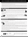
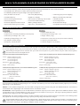
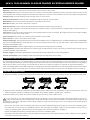
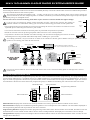
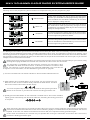
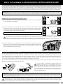
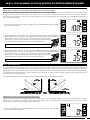
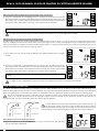
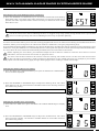
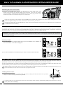
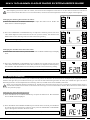
T
MX-V 3-CHANNEL 2.4GHZ RADIO SYSTEM USER'S GUIDE
User's Guide
1
MX-V 3-CHANNEL 2.4GHZ RADIO SYSTEM USER'S GUIDE
TAbLE Of CONTENTS
Introduction.........................................................................................................................................................................................................................................Page 2
Packaging............................................................................................................................................................................................................................................Page 2
Service and Support ......................................................................................................................................................................................................................Page 3
Safety .....................................................................................................................................................................................................................................................Page 3
FCC Compliance Statement ......................................................................................................................................................................................................Page 3
2.4GHz Frequency Band Precautions ...................................................................................................................................................................................Page 4
Transmitter Precautions ...............................................................................................................................................................................................................Page 4
Receiver Precautions .....................................................................................................................................................................................................................Page 4
Servo Connectors ............................................................................................................................................................................................................................Page 4
System Features ..............................................................................................................................................................................................................................Page 5
System Specifications ...................................................................................................................................................................................................................Page 5
Servo Recommendations............................................................................................................................................................................................................Page 5
Transmitter Battery Specifications ..........................................................................................................................................................................................Page 5
Transmitter and Receiver Diagrams ......................................................................................................................................................................................Page 6
Transmitter and Receiver Diagram Descriptions ............................................................................................................................................................Page 7
Transmitter Low Voltage Alarm ................................................................................................................................................................................................Page 7
Battery Installation ...........................................................................................................................................................................................................................Page 7
Receiver Connections and Mounting ....................................................................................................................................................................................Page 8
LCD and Programming Keys .....................................................................................................................................................................................................Page 8
Transmitter and Receiver Binding...........................................................................................................................................................................................Page 9
Throttle Fail Safe Programming ............................................................................................................................................................................................ Page 10
Programming Menus Overview ............................................................................................................................................................................................ Page 10
Dual Rate .......................................................................................................................................................................................................................................... Page 11
End Point Adjustment ................................................................................................................................................................................................................. Page 11
Exponential ...................................................................................................................................................................................................................................... Page 13
Anti-Lock Braking .......................................................................................................................................................................................................................... Page 14
Servo Trim ........................................................................................................................................................................................................................................ Page 15
Model Select ................................................................................................................................................................................................................................... Page 16
Servo Sub-Trim .............................................................................................................................................................................................................................. Page 16
Servo Reversing ............................................................................................................................................................................................................................ Page 17
Model Naming ............................................................................................................................................................................................................................... Page 18
Voltage Monitor ............................................................................................................................................................................................................................. Page 18
Modulation Type ........................................................................................................................................................................................................................... Page 18
Troubleshooting Guide .............................................................................................................................................................................................................. Page 19
Glossary of Terms......................................................................................................................................................................................................................... Page 19
Index .................................................................................................................................................................................................................................................... Page 21
Notes................................................................................................................................................................................................................................................... Page 23
INTRODUCTION
Congratulations! We appreciate your purchase of the Airtronics MX-V 3-Channel 2.4GHz FHSS-2 radio control system. This User's
Guide is intended to acquaint you with the many unique features of your new radio control system. Please read this User's Guide
carefully so that you may obtain maximum success and enjoyment from the operation of your new radio control system.
The MX-V 3-Channel 2.4GHz FHSS-2 radio control system has been designed for the entry level user, but still retains the easy
programming, precise control and ergonomic layout found in our higher-end systems. The MX-V boasts a number of features that
will make it perfect for use with both cars, trucks and boats. We wish you the best of success and fun with your new purchase.
Additional Airtronics 2.4GHz receivers can be purchased and paired with the MX-V transmitter. Please note that due
to differences in the implementation of 2.4GHz technology among different manufacturers, only Airtronics brand 2.4GHz
FHSS-2 surface receivers are compatible with your radio control system. Please visit your local Airtronics dealer or our website at
http://www.airtronics.net for more information.
PACKAGING
The packaging of your MX-V 3-Channel 2.4GHz FHSS-2 radio control system has been specially designed for the safe transportation
and storage of the radio control system's components. After unpacking your radio control system, do not discard the packaging
materials. Save the packaging materials for future use if you ever need to send your radio control system to us for service or to
store your radio control system if you don't plan on using it for an extended period of time.
2
T
MX-V 3-CHANNEL 2.4GHZ RADIO SYSTEM USER'S GUIDE
SERVICE AND SUPPORT
If you have any questions or concerns, we're here to help. If you encounter a problem with your radio control system, first check
the Troubleshooting Guide on page 19. If the Troubleshooting Guide is unable to help, please contact us directly.
In North America Only:
Global Services
18480 Bandilier Circle
Fountain Valley, CA 92708
Telephone: 1-714-963-0329
Fax: 1-714-964-6236
Email: [email protected]
If you purchased your radio outside of North America, please contact your regional Airtronics/Sanwa agent for service and support.
SAfETY
This is a high-output, full-range radio control system that should well exceed the range needed for any surface model. For safety,
the user should perform a range test at the area of operation to ensure that the radio control system has complete control of the
model at the farthest reaches of the operational area. Rather than operating the model, we recommend that the user enlist the
help of a fellow modeler to walk the model to the farthest reaches of the track (or for boats, to walk the shore line well in excess
of the operational distance of the boat), then test for proper operation.
• Be certain to read this User's Guide in its entirety.
• 'Safety First' for yourself, others and your equipment.
• Observe all the rules of the field, track or lake where you operate your radio control equipment.
• If at any time during the operation of your model, should you feel or observe erratic operation or abnormality, end your operation
as quickly and safely as possible. DO NOT operate your model again until you are certain the problem has been corrected.
TAKE NO CHANCES.
• Your model can cause serious damage or injury. Please use caution and courtesy at all times.
• Do not expose the radio control system to water or excessive moisture.
• Waterproof the receiver and servos by placing them in a water-tight radio box when operating R/C model boats.
• If you have little to no experience operating R/C models, we recommend you seek the assistance of an experienced modeler
or your local hobby shop for guidance.
• The Low Voltage Alarm will sound when the transmitter battery voltage drops to the minimum threshold of 4.6 volts. If this
occurs, stop using the transmitter as soon as is safely possible, then replace the transmitter batteries.
This radio control system operates on the 2.4GHz frequency band. The 2.4GHz connection is determined by the transmitter
and receiver pair. Unlike ordinary crystal-based systems, your model can be used without frequency control.
fCC COMPLIANCE STATEMENT
This equipment has been tested and found to comply with the limits for a Class B digital device, pursuant to Part 15 of the FCC
Rules. These limits are designed to provide reasonable protection against harmful interference in a residential installation. This
equipment generates, uses, and can radiate radio frequency energy and, if not installed and used in accordance with the operating
instructions, may cause harmful interference to radio communications. However, there is no guarantee that interference will not
occur in a particular installation.
If this equipment does cause harmful interference to radio or television reception, which can be determined by turning the
equipment OFF and ON, the user is encouraged to try to correct the interference by one or more of the following measures:
• Reorient or relocate the receiving antenna.
• Increase the separation between the equipment and the receiver.
• Connect the equipment into an outlet on a circuit different from that to which the receiver is connected.
• Consult the dealer or an experienced technician for help.
This device complies with Part 15 of the FCC Rules and with RSS-210 of Industry Canada. Operation is subject to the following
two conditions:
1) This device may not cause harmful interference, and....
2) This device must accept any interference received, including interference that may cause undesired operation.
Changes or modifications made to this equipment not expressly approved by Airtronics may void the FCC authorization to
operate this equipment.
RF Exposure Statement:
This transmitter has been tested and meets the FCC RF exposure guidelines when used with the Airtronics accessories supplied
or designated for this product, and provided at least 20cm separation between the antenna the user's body is maintained. Use of
other accessories may not ensure compliance with FCC RF exposure guidelines.
3
MX-V 3-CHANNEL 2.4GHZ RADIO SYSTEM USER'S GUIDE
2.4GHZ fREqUENCY bAND PRECAUTIONS
• The 2.4GHz frequency band may be used by other devices, or other devices in the immediate area may cause interference on
the same frequency band. Always before use, conduct a bench test to ensure that the servos operate properly. Also, conduct
checks with the transmitter as distant as possible from your model.
• The response speed of the receiver can be affected if used where multiple 2.4GHz radio controllers are being used, therefore,
carefully check the area before use. If response seems slow during use, stop your model immediately and discontinue use.
• If the 2.4GHz frequency band is saturated (too many radio controllers on at once), as a safety precaution, the radio control
system may not bind. This ensures that your radio control system does not get hit by interference. Once the frequencies have
been cleared, or the saturation level has dropped, your radio control system should be able to bind without any problems.
TRANSMITTER PRECAUTIONS
• To prevent possible damage to your servos or a runaway model, turn the transmitter ON first, then turn
the receiver ON. After running your model, turn the receiver OFF first, then turn the transmitter OFF.
• Before use, double-check that the transmitter and receiver batteries have sufficient power.
• The transmitter features an internal antenna installed inside the front portion of the transmitter.
Do NOT cover the front of the transmitter in any way during use! Doing so can block the RF signal, resulting in loss
of control of your model.
• During use, hold the transmitter so that its orientated as close to vertical as possible at all times. This provides the best RF
signal between the transmitter and the receiver. Try not to ever 'follow' your model with the transmitter, as this can result in a
weakened RF signal.
• Do not expose the transmitter or any other components to excessive heat, moisture, fuel, exhaust residue, etc.
• Do not press the Bind Button during use. The signal is interrupted while the Bind
Button is pressed. It may also require a short time to restore the signal after
releasing the Bind Button, which can be dangerous.
• If the outer case becomes dirty, it can be cleaned with a soft dry cloth. If the outer case becomes
soiled, it can be cleaned with a damp cloth and liquid detergent.
• Do not use any solvents to clean the outer case. Solvents will damage the finish.
RECEIVER PRECAUTIONS
• The antenna wire is delicate, therefore, handle with care. Do not pull on the antenna wire with force.
• Do not cut the antenna wire shorter or extend the antenna wire.
• The antenna wire can be bent into gentle curves, however, do not bend it acutely, or repeatedly bend it, or the antenna wire
can be damaged.
• The antenna wire should be installed into a vertical plastic tube per your particular model's assembly
instructions. Keep the receiver antenna as far away from the motor, battery and ESC as possible.
• There is a danger of runaway operation if connectors shake loose during use. Make sure that the receiver,
servo(s) and switch connectors are securely fitted.
• The receiver is susceptible to vibration, shock and moisture. Take appropriate measures to protect against vibration and
moisture. Failure to take appropriate measures could result in runaway operation or damage to the receiver. We suggest
wrapping the receiver in shock-absorbing foam or securing it with double-sided foam tape when installing it into your model.
• When installing the receiver and routing the receiver antenna, avoid contact with any carbon or metal chassis components.
Contact between metal parts mounted on a model can result in electrical noise, which can adversely effect receiver
performance and possibly result in runaway operation or damage to your model.
• With electric-powered models, be sure to fit any brushed motors with a noise suppression capacitor. Without a noise suppression
capacitor, excessive electrical noise generation can cause runaway operation and/or result in damage to your model.
• The receiver does not feature BEC circuitry. If using an electronic speed control, verify that it features BEC circuitry to drop
the receiver voltage between 4.8v to 7.4v.
SERVO CONNECTORS
The receiver included with your radio control system uses Airtronics 'Z' connectors, which are electronically compatible with the
servos of other radio control system manufacturers. The connectors are rugged, but should be handled with care.
- = Negative (Black)
+ = Positive (Red)
S = Signal (Blue)
If using another brand of servo, double-check the polarity
of the servo connector prior to plugging it into the receiver.
When unplugging the servo connector, don't pull on the servo wire itself. This could result in damage to the servo wire pins
in the plastic plug. Always grasp the plastic connector itself.
4
T
MX-V 3-CHANNEL 2.4GHZ RADIO SYSTEM USER'S GUIDE
SYSTEM fEATURES
• 3-Channel Full-Range 2.4GHz FHSS-2 Digital Proportional Computer Radio for Cars, Trucks and Boats
• Compatible with all Airtronics 2.4GHz FHSS-2 Surface Receivers
• 4-Cell Battery Holder for Lighter Weight and Improved Balance
• Easy-to-Read LCD Screen
• Anti-Lock (ABS) Braking
• Textured grip to prevent slipping
• 10 Model Memory
• Digital Trim Display
• Battery-Less Memory Retention
• Servo Reversing All Channels
• Servo Sub-Trim Steering and Throttle
• Throttle Fail Safe
• Dual Rate Steering
• 3-Character Model Naming
• Low Voltage Alarm
• End Point Adjustment All Channels
• Battery Voltage Monitor
• Over 1000 Foot Range
• Exponential Steering and Throttle
• Ergonomic, Comfortable Feel
• Compatible with Analog or Digital Servos
SYSTEM SPECIfICATIONS
Transmitter:
Receiver:
• Model: MX-V
• Model: 92625 (RX-37E)
• Output Power: 100mW (FH2/FH2F) / 10mW (DS2)
• Nominal Input Voltage: 4.8v ~ 7.4v
• Nominal Input Voltage: 4.8v ~ 6.0v
• Weight: 0.25oz (7.1gr)
• Operating Voltage Range: 4.0v ~ 9.6v
• Dimensions: 1.18 x 1.04 x 0.57in (30.0 x 26.5 x 14.5mm)
• Dry Weight: 11.64oz (330gr)
• Frequency: 2.4GHz FHSS-2
• Frequency: 2.4GHz FHSS-2
• Fail Safe Support: Yes (Throttle )
SERVO RECOMMENDATIONS
We recommend using Airtronics brand servos with your MX-V 3-Channel 2.4GHz FHSS-2 radio control system. These are a few
of our more popular servos. Visit your local Airtronics dealer or www.airtronics.net for pricing, availability and more selection.
Both analog and digital servos will work with your radio control system. To get the most out of your radio control system,
we recommend the use of digital servos.
94722 (SDX-1322) Digital Standard Ball Bearing Servo
94775M (SDX-772) Digital High-Power Metal Gear Dual Ball Bearing Servo
Torque: 50oz/in (3.6kg/cm @ 4.8v)
61oz/in (4.4kg/cm @ 6.0v)
Speed: 0.17 sec/60º @ 4.8v
0.14 sec/60º @ 6.0v
Dimensions: 1.54 x 0.79 x 1.42in
(39.1 x 20.0 x 36.0mm)
Weight: 1.55oz (43.9gr)
Torque: 124oz/in (8.9kg/cm @ 4.8v)
151oz/in (10.9kg/cm @ 6.0v)
Speed: 0.17 sec/60º @ 4.8v
0.13 sec/60º @ 6.0v
Dimensions: 1.54 x 0.78 x 1.50in
(39.0 x 20.0 x 37.4mm)
Weight: 1.93oz (56gr)
94746M (SDX-801) Digital Metal Gear Low-Profile Dual Ball Bearing Servo
94780M (SDX-901) Digital High-Power Metal Gear Dual Ball Bearing Servo
Torque: 80oz/in (5.8kg/cm @ 4.8v)
89oz/in (6.4kg/cm @ 6.0v)
Speed: 0.10 sec/60º @ 4.8v
0.08 sec/60º @ 6.0v
Dimensions: 1.59 x 0.83 x 1.04in
(40.4 x 21.1 x 26.4mm)
Weight: 1.77oz (50gr)
Torque: 361oz/in (26.0kg/cm @ 4.8v)
423oz/in (30.5kg/cm @ 6.0v)
Speed: 0.19 sec/60º @ 4.8v
0.15 sec/60º @ 6.0v
Dimensions: 1.60 x 0.83 x 1.50in
(40.6 x 21.1 x 38.1mm)
Weight: 2.33oz (66gr)
TRANSMITTER bATTERY RECOMMENDATIONS
The transmitter's Operating Voltage Range is 4.0 ~ 9.6 volts. This allows you to use several different battery options (not included),
depending on your preference.
Alkaline - In the default configuration, the transmitter is designed to be powered using four 'AA' Alkaline batteries. This results in
a transmitter that is lightweight and well-balanced for unmatched comfort.
Ni-Cd/Ni-MH - Rechargeable Ni-Cd or Ni-MH batteries of desired capa city can be used in place of the Alkaline batteries. Using
rechargeable Ni-Cd or Ni-MH batteries is more convenient and cheaper in the long run. The higher capacity batteries will also
provide longer usage time than most Alkaline batteries.
Li-Po or Li-Fe - A 2 cell Li-Po battery pack or a 2 cell Li-Fe battery pack can be used to power the transmitter. These battery packs
are popular due to their light weight and high capacity for long usage time between charges.
Rechargeable batteries will need to be charged with a dedicated charger outside of the transmitter. Transmitter power
output, range and speed are the same, regardless of the battery voltage and type used. If using a Li-Po or Li-Fe battery pack,
please obverse the warnings in the Battery Installation section on page 7.
5
MX-V 3-CHANNEL 2.4GHZ RADIO SYSTEM USER'S GUIDE
TRANSMITTER AND RECEIVER DIAGRAMS
Use the diagrams below to familiarize yourself with the different parts of your MX-V 3-Channel 2.4GHz FHSS-2 transmitter and
92625 (RX-37E) receiver. Descriptions of these parts can be found in the Transmitter and Receiver Layout Descriptions section
on the next page.
The transmitter antenna is mounted internally and is located in the front portion of the transmitter. When you're driving
your model, hold the transmitter so that it's orientated as close to vertical as possible at all times and try not to 'follow' your
model with the transmitter. This provides the best RF signal between the transmitter and the receiver. Do NOT cover the front of
the transmitter in any way during use! Doing so can block the RF signal, resulting in the loss of control of your model.
Throttle Trim
Switch
Steering Trim
Switch
Dual Rate
Switch
Power Indicator
Auxiliary Lever
Antenna (Inside Case)
Steering Wheel
Power Switch
Bind Button
Throttle Trigger
Grip
RIGHT SIDE VIEw
LCD Screen
Battery Compartment
RECEIVER
Antenna Wire
TOP VIEw
Bind LED
Programming Keys
Bind Button
Battery/Switch Harness
Auxiliary (Channel 3)
Throttle (Channel 2)
Steering (Channel 1)
= Signal
6
= Positive
= Negative
T
MX-V 3-CHANNEL 2.4GHZ RADIO SYSTEM USER'S GUIDE
TRANSMITTER AND RECEIVER DIAGRAM DESCRIPTIONS
Antenna: Transmits the signal from the transmitter to the receiver in the model.
Antenna Wire: Receives the transmitter signal. The antenna wire should be installed through a nylon tube (antenna tube) in the
vertical position for the best reception. Do not alter the length of the antenna or the operation of the receiver will be compromised.
Auxiliary Lever: Controls Auxiliary channel 3 High and Low servo travel.
Battery Compartment: Houses the four 'AA' Alkaline cells that power the transmitter.
Bind Button: Used in the process of binding the transmitter and receiver.
Bind LED: Displays the current status of the receiver.
Dual Rate Switch: Used to adjust Steering Dual Rate quickly and easily while your driving.
Grip: The grip is molded in an ergonomic shape for increased comfort, control and feel. It's moulded with a textured surface to
help prevent slipping.
LCD Screen: The heart of the programming and display features of the transmitter. All programming and transmitter display
functions are shown on the LCD screen.
Power Indicator: Illuminates red, indicating the transmitter is turned ON.
Power Switch: Turns the transmitter ON and OFF.
Programming Keys: The programming keys consist of four different keys - the MENU UP key, the MENU DOWN key, the INCREASE
key and the DECREASE key. These four keys are used to program the functions of your transmitter, select saved models and
change the Modulation Type.
Steering Trim Switch: Used to adjust Steering Trim quickly and easily while you're driving.
Steering Wheel: Proportionally operates the model's right and left steering control. The steering wheel features a foam grip for
increased comfort, control and feel.
Throttle Trigger: Controls the speed of the model, both forward and backward, or the model's brake.
Throttle Trim Switch: Used to adjust Throttle Trim quickly and easily while you're driving.
TRANSMITTER LOw VOLTAGE ALARM
The transmitter features a Low Voltage Alarm to warn you when the transmitter batteries need to be replaced or recharged (if
using rechargeable batteries). The Low Voltage Alarm will sound when the transmitter batteries reach 4.6 volts. If the Low Voltage
Alarm sounds while you are driving, you should stop as soon as it's safe, then replace or recharge the transmitter batteries.
If the Low Voltage Alarm sounds after replacing or recharging the transmitter batteries, there may be a problem with the transmitter.
If this occurs, please contact Airtronics Customer Service using the information in the Service and Support section on page 3.
bATTERY INSTALLATION
1) Remove the battery cover from the bottom of the transmitter by pushing firmly on the battery cover in the direction of the arrow.
2) Install four fresh 'AA' Alkaline batteries into the battery holder, making sure that the polarity is correct. The direction that each
battery should be installed is molded into the bottom of the battery holder (+ positive and - negative).
3) Slide the battery cover back onto the transmitter and push it firmly until it 'clicks' closed.
If you choose to use rechargeable batteries (as described in the Transmitter Battery Recommendations section on
page 5), they will need to be charged with a dedicated charger outside of the transmitter. Transmitter power output, range
and speed are the same, regardless of the battery voltage and type used. If using a Li-Po or Li-Fe battery pack, please observe
the following warnings:
• Do not use a 3S Li-Po or 3S Li-Fe battery pack or the transmitter will be damaged. Use only a 2S Li-Po or 2S Li-Fe battery pack.
• You will need to remove the dry cell battery holder in the transmitter and solder a plug on the transmitter's power wires to
match your battery pack. Please observe correct polarity (red + positive and black - negative).
• Observe all safety precautions provided with your Li-Po or Li-Fe battery pack.
• Damage to the transmitter and/or receiver caused by improper use, wrong battery type, incorrect voltage or reverse polarity
will not be covered under warranty.
7
MX-V 3-CHANNEL 2.4GHZ RADIO SYSTEM USER'S GUIDE
RECEIVER CONNECTIONS AND MOUNTING
Use the diagram below to make the connections to the 92625 (RX-37E) 3-Channel 2.4GHz FHSS-2 receiver included with your MX-V
3-Channel 2.4GHz FHSS-2 radio control system.
The receiver's Nominal Input Voltage is 4.8 ~ 7.4 volts. A 2 cell Li-Po or 2 cell Li-Fe battery pack can be used to power the
receiver without the use of a voltage regulator. In addition, this allows you to take advantage of the higher torque and speed
provided by using 7.4 volt digital servos.
Use a 2 cell Li-Po or 2 cell Li-Fe battery pack ONLY if your servos are rated to handle the higher voltage.
Antenna
Wire
If you're using an Electronic Speed Control with BEC circuitry, verify that it reduces the voltage to
between 4.8 and 7.4 volts before making your connections and turning your radio control system ON.
Antenna
Tube
• We suggest binding the transmitter and receiver and making all receiver connections to check for correct
operation prior to mounting the receiver in your model.
• The receiver should be mounted as far away from any electrical components as possible.
• Route the receiver antenna up through a plastic tube so that it is in the vertical position.
• To protect the receiver from vibration and other damage, we recommend wrapping the receiver in shock
absorbing foam or using double-sided foam tape when installing it in your model.
As a safety precaution, set your model on a stand so the wheels are off the ground before turning on your radio control
system or connecting your motor for the first time.
Receiver
Switch (Included)
'AA' Dry Cell Battery Holder (Included),
4.8v ~ 6.0v Ni-Cd/Ni-MH or 2S Li-Po or 2S Li-Fe
Batt
Switch
Receiver
Auxiliary
CH3
To Battery
GLOw/GAS
OR MSC
SETUP
To Motor
Steering
CH1
Steering
Servo CH1
Throttle
Servo CH2
Auxiliary
Servo CH3
ESC
ESC
SETUP
Do not use servos rated for 4.8 or 6.0 volts with a 2S Li-Po or Li-Fe receiver battery pack or damage to the servos
could result.
LCD AND PROGRAMMING KEYS
The transmitter features four programming keys that are used to facilitate transmitter programming. The programming keys
consist of four different keys - the MENU UP key, the MENU DOWN key, the INCREASE key and the DECREASE key. These four
keys are used to program the functions of your transmitter, select saved models and change the Modulation Type. This section
summarizes the functions of each of the four programming keys, in addition to describing the main areas of the LCD screen
Model Number
Voltage Monitor
Programming Window
Menu Selections
Menu Selections
Model Number: Displays the model that is currently loaded into memory. Up to 10 different models can be stored.
Menu Selections: Displays the available Programming Menus. The currently Active menu will flash. The information displayed in
the Programming Window will vary based on the menu selected.
Programming Window: Displays transmitter programming information. When the transmitter is turned ON, the BATT menu will
be selected, the current model number will be shown and the Voltage Monitor will display the transmitter's current voltage.
Voltage Monitor: Displays the current voltage of the transmitter batteries. When the transmitter batteries reach 4.6 volts, the Low
Voltage Alarm will sound.
8
T
MX-V 3-CHANNEL 2.4GHZ RADIO SYSTEM USER'S GUIDE
LCD AND PROGRAMMING KEYS
Selecting menus and programming the transmitter is accomplished using the four programming keys.
PROGRAMMING KEY
NAME
FUNCTION
MENU DOWN
Cycles down through the list of menus and sub-menu
functions you would like to make programming changes to.
Press the MENU UP and MENU DOWN keys at the same
time to display the Voltage Monitor.
MENU UP
Cycles up through the list of menus and sub-menu functions
you would like to make programming changes to. Press
the MENU UP and MENU DOWN keys at the same time to
display the Voltage Monitor.
INCREASE
Increases Programming Values and used to select models.
Press the INCREASE and DECREASE keys at the same time
to reset Programming Values to default.
DECREASE
Decreases Programming Values and used to select models.
Press the INCREASE and DECREASE keys at the same time
to reset Programming Values to default.
TRANSMITTER AND RECEIVER bINDING
The Binding function allows you to bind the transmitter and receiver pair. When new, it is necessary to pair the transmitter and
receiver to prevent interference from radio controllers operated by other users. This operation is referred to as 'binding'. Once
the binding procedure is complete, the setting is remembered even when the transmitter and receiver are turned OFF, therefore,
this procedure usually only needs to be done once. Bind codes are unique to each transmitter and receiver pair, so you can bind
multiple receivers to the same transmitter.
Before beginning the binding procedure, connect the switch harness, servos and the receiver battery to your receiver, using
the diagram on page 8. Make sure that both the transmitter and the receiver are turned OFF.
The transmitter is compatible with FH2 receivers, however, the transmitter is also
compatible with FH2F and DS2 receivers. To bind the transmitter to an FH2F or DS2
receiver (not common in North America), the transmitter Modulation Type must first be
changed. For more information, see the Modulation Type section on page 18.
1) Turn the transmitter ON. The Power Indicator on the transmitter will illuminate red.
2) While holding down the Bind Button on the receiver, turn the receiver ON. The
Bind LED on the receiver will flash slowly. Release the Bind Button. The Bind
LED on the receiver will continue to flash slowly.
You must complete step 3 below within 10 seconds after pressing the Bind
Button on the receiver or you will need to start the binding procedure over.
3) Quickly press the Bind Button on the transmitter. The Bind LED on the receiver will flash
rapidly, go out momentarily, then illuminate solid blue, indicating the binding procedure
is complete.
When the binding procedure is successful, the Bind LED on the receiver will stay solid blue when both the transmitter and
receiver are turned ON. If the Bind LED on the receiver is flashing rapidly or not illuminated at all, the transmitter and receiver
are not paired. In this case, turn both the transmitter and receiver OFF, then repeat the binding procedure again.
Under some circumstances, the receiver may not operate after turning the transmitter and receiver ON. If this occurs,
perform the binding procedure again.
9
MX-V 3-CHANNEL 2.4GHZ RADIO SYSTEM USER'S GUIDE
THROTTLE fAIL SAfE PROGRAMMING
The Throttle Fail Safe function automatically moves the throttle servo to a predetermined position in the event that the signal
between the transmitter and the receiver is interrupted, whether due to signal degradation or to low transmitter battery voltage.
For example, the Throttle Fail Safe function can be set so that the throttle returns to idle or the brake engages so that your model
doesn't run away if the signal is lost.
The Throttle Fail Safe function will not operate if the receiver loses power, for example, if the receiver battery comes loose
or if the receiver battery is drained.
Setting the Throttle Fail Safe Position:
1) Turn the transmitter ON, then turn the receiver ON. The Power Indicator on the transmitter should be illuminated and the Bind
LED on the receiver should also be illuminated.
2) Move the transmitter steering wheel and throttle trigger to verify correct servo movement.
3) Move the throttle trigger to the desired Throttle Fail Safe position. While holding the throttle trigger in the desired position, press
and HOLD the Bind Button on the receiver. After approximately 2 seconds, the Bind LED will begin to flash slowly. Continue
holding the Bind Button until the Bind LED begins to flash rapidly (approximately 2 more seconds). Once the Bind LED begins
to flash rapidly, release the Bind Button.
4) Turn the transmitter OFF to test the Throttle Fail Safe operation. The throttle servo should move to the position that you set
previously in step 3.
Clearing the Throttle Fail Safe Setting:
1) To clear the currently programmed Throttle Fail Safe setting, re-bind the transmitter and receiver pair.
PROGRAMMING MENUS OVERVIEw
When the transmitter is turned ON, the Voltage Monitor will be displayed. To cycle through the different Programming Menus,
press the MENU UP or MENU DOWN keys. The currently selected Programming Menu will flash.
When you make Programming Value changes, those changes are reflected immediately. There is no need to 'save' your
changes.
If you're in a Programming Menu when you turn the transmitter OFF, the Voltage Monitor will be displayed when the transmitter is
turned back ON. If you adjust the Steering Trim, Throttle Trim, or Steering Dual Rate using either of the three switches, the value
will be displayed on the LCD screen for approximately 5 seconds, then revert to the last menu you were in.
Use the flow chart below to familiarize yourself with the layout of the various Programming Menus available. Each is available by
repeatedly pressing the MENU UP or MENU DOWN keys.
D/R-ST
EPA-ST R/L
EXP-ST
EPA-TH F/B
EXP-TH
ALB-TH
TRIM-ST
MODEL
TRIM-TH
SUB-T-ST
REV-ST
SUB-T-TH
REV-TH
EPA-AUX H/L
MENU
NAME
BATT
REV-AUX
MENU NAME
MENU DESCRIPTION
PAGE #
D/R
Dual Rate
Adjust Steering Dual Rate
Page 11
EPA
End Point Adjustment
Adjust Steering, Throttle and Auxiliary End Points
Page 11
EXP
Exponential
Adjust Steering and Throttle Exponential
Page 13
ALB
Anti-Lock Braking
Program Throttle Anti-Lock Braking
Page 14
TRIM
Servo Trim
Adjust Steering and Throttle Servo Trim
Page 15
MODEL
Model Select
Select Programmed Models 1 Through 10
Page 16
SUB-T
Servo Sub-Trim
Adjust Steering and Throttle Servo Sub-Trim
Page 16
REV
Servo Reversing
Adjust Steering, Throttle and Auxiliary Servo Travel Direction
Page 17
NAME
Model Name
Name Your Models
Page 18
BATT
Voltage Monitor
Displays Transmitter Battery Voltage and Current Model Number
Page 18
10
T
MX-V 3-CHANNEL 2.4GHZ RADIO SYSTEM USER'S GUIDE
D/R - DUAL RATE
The Dual Rate function allows you to change the control authority of your model's steering by changing the amount of servo
travel relative to control input. For example, by increasing the Dual Rate, you can make the steering servo travel more which might
prevent your model from pushing during turns. If your model oversteers during turns, you can reduce the amount of Dual Rate.
IMPORTANT: Prior to programming the Dual Rate function, you should adjust the Left and Right Steering End Points, using the
End Point Adjustment function. For more information, see the End Point Adjustment section below.
Adjusting the Steering Dual Rate Percentage Value:
1) Press the MENU UP or MENU DOWN keys to open the D/R menu. D/R will flash
and ST 100% will be displayed.
2) Press the INCREASE or DECREASE keys to change the Steering Dual Rate
percentage value. When the Steering Dual Rate percentage value is decreased,
steering servo travel is decreased. When the Steering Dual Rate percentage value
is increased, steering servo travel is increased.
D/R ST setting range is 0% to 100%. The default setting is 100%.
Dual Rate is a percentage of End Point Adjustment. For example, if you set the Steering Dual Rate percentage value to
100%, the steering will travel the same amount as defined by your Steering End Point Adjustment programming. If you
set the Steering Dual Rate percentage value to 50%, the steering will travel half that amount.
3) Steering Dual Rate can be adjusted at any time while driving using the Dual Rate
Switch. Press the Dual Rate Switch forward to increase the Steering Dual Rate
percentage value and press the Dual Rate Switch backward to decrease the
Steering Dual Rate percentage value.
EPA - END POINT ADjUSTMENT
The End Point Adjustment function allows you to adjust servo travel in each direction. This makes it possible to balance servo
travel in both directions and set the maximum desired amount of servo travel. For example, on a gas-powered model, if you pull
the throttle trigger and the carburetor does not open completely, you can increase the Throttle Forward End Point Adjustment so
that the carburetor opens completely. Another example is with steering. If your model turns sharper to the right than to the left,
you can increase the Steering Left End Point Adjustment to balance the steering.
The End Point Adjustment function can be adjusted for the Steering channel (Left and Right), the Throttle channel (Forward and
Brake) and Auxiliary Channel 3 (High and Low).
Throttle
Steering
If you're using an electronic speed control, the
Throttle Forward and the Throttle Brake End Point
Adjustment percentage values are both generally set to
100%, although the Throttle Forward direction may need
to be increased to achieve full power. In some cases the
End Point Adjustments can also be set directly via the
electronic speed control.
WARNING: End Point Adjustment percentage values should not be increased to the point where your linkages and/or servos
bind when moved all the way in either direction. Binding will cause the servos to 'buzz', draining the receiver battery quickly
and eventually damaging the servos.
Before making End Point Adjustments, the servo horns need to be centered. Install the servo horns onto the servos, making
sure that they're as close to being centered as possible, then use the Servo Sub-Trim function to center the servo arms
exactly. For more information, see the Servo Sub-Trim section on page 16.
11
MX-V 3-CHANNEL 2.4GHZ RADIO SYSTEM USER'S GUIDE
EPA - END POINT ADjUSTMENT
Adjusting the Steering End Point Adjustment Percentage Values:
Your model’s turning radius can differ from left to right because of variations in linkage, suspension balance, tire diameter or
weight distribution. In such cases, Left Steering servo travel and Right Steering servo travel are adjustable using the End Point
Adjustment function.
1) Press the MENU UP or MENU DOWN keys to open the EPA menu. EPA will flash
and ST L or ST R 100% will be displayed.
2) Rotate the steering wheel to the left and release it. ST L should be displayed. Press
the INCREASE or DECREASE keys to increase or decrease the Steering Left End
Point Adjustment percentage value. Increasing the percentage value
will increase steering servo travel in that direction and decreasing the
percentage value will decrease steering servo travel in the that direction.
EPA ST L setting range is 0% to 150%. The default setting is 100%.
3) Rotate the steering wheel to the right and release it. ST R should be displayed.
Press the INCREASE or DECREASE keys to increase or decrease the Steering Right
End Point Adjustment percentage value. Increasing the percentage
value will increase steering servo travel in that direction and decreasing
the percentage value will decrease steering servo travel in the that direction.
EPA ST R setting range is 0% to 150%. The default setting is 100%.
Adjusting Throttle End Point Adjustment:
Your model's carburetor may not open completely or it may open too much and cause the throttle servo to bind. If you're using
an electronic speed control, the electronic speed control may not command full power or the brake may not engage adequately.
In such cases, Throttle Forward servo travel and Throttle Brake servo travel can be independently adjusted using the End Point
Adjustment function.
1) From within the EPA menu, press the MENU UP or MENU DOWN keys to display
TH F or TH B 100%.
2) Pull the throttle trigger and release it. TH F should be displayed. Press the
INCREASE or DECREASE keys to increase or decrease the Throttle Forward End
Point Adjustment percentage value. Increasing the percentage value
will increase throttle servo travel in that direction and decreasing the
percentage value will decrease throttle servo travel in the that direction.
EPA TH F setting range is 0% to 150%. The default setting is 100%.
3) Push the throttle trigger and release it. TH B should be displayed. Press the
INCREASE or DECREASE keys to increase or decrease the Throttle Brake End Point
Adjustment percentage value. Increasing the percentage value will
increase throttle servo travel in that direction and decreasing the
percentage value will decrease throttle servo travel in the that direction.
EPA TH B setting range is 0% to 150%. The default setting is 100%.
12
T
MX-V 3-CHANNEL 2.4GHZ RADIO SYSTEM USER'S GUIDE
EPA - END POINT ADjUSTMENT
Adjusting the Auxiliary Channel 3 End Point Adjustment Percentage Values:
Auxiliary Channel 3 can be used for a number of different uses. One of the more common uses would be for the reverse function
in a glow-powered monster truck. Often, the transmission only requires a small amount of travel, but the servo binds because
of too much servo travel. In such a case, Auxiliary High servo travel and Auxiliary Low servo travel are adjustable using the End
Point Adjustment function.
1) From within the EPA menu, press the MENU UP or MENU DOWN keys to display
AUX H or AUX L 100%.
2) Push the Auxiliary Lever down. AUX L should be displayed. Press the INCREASE or
DECREASE keys to increase or decrease the Auxiliary Low End Point Adjustment
percentage value. Increasing the percentage value will increase
auxiliary servo travel in that direction and decreasing the percentage
value will decrease auxiliary servo travel in the that direction.
EPA AUX L setting range is 0% to 150%. The default setting is 100%.
3) Push the Auxiliary Lever up. AUX H should be displayed. Press the INCREASE or
DECREASE keys to increase or decrease the Auxiliary Low End Point Adjustment
percentage value. Increasing the percentage value will increase
auxiliary servo travel in that direction and decreasing the percentage
value will decrease auxiliary servo travel in the that direction.
EPA AUX H setting range is 0% to 150%. The default setting is 100%.
EXP - EXPONENTIAL
The Exponential function allows you to vary the amount of servo travel in relation to the movement of the steering wheel and
throttle trigger near the Neutral positions to change the way those functions react to control movement. Decreasing the Exponential
percentage values will soften the control feel around Neutral and increasing the Exponential percentage values will heighten the
control feel around Neutral. Using a lower negative value allows for smoother control. Using a higher positive value may result
in more 'twitchy' control response.
The Exponential function can be adjusted for the Steering channel and the Throttle channel.
Adjusting the Steering Exponential Percentage Value:
Steering Exponential can be variably adjusted from Mild through Linear to Quick to allow you to set the most effective steering
response for your model. Generally, if your model over-steers, reduce the Exponential percentage value, and if your model
under-steers, increase the Exponential percentage value.
1) Press the MENU UP or MENU DOWN keys to open the EXP menu. EXP will flash
and ST 0% will be displayed.
13
MX-V 3-CHANNEL 2.4GHZ RADIO SYSTEM USER'S GUIDE
EXP - EXPONENTIAL
Adjusting the Steering Exponential Percentage Value, Continued:
2) Press the INCREASE or DECREASE keys to change the Steering Exponential
percentage value. Decreasing the Steering Exponential percentage value will make
the steering less sensitive around Neutral and increasing the Steering Exponential
percentage value will make the steering more sensitive around Neutral.
EXP ST setting range is -100% (Mild) to 100% (Quick). The default setting is 0% (Linear).
Changes to the Steering Exponential percentage value affects the Left and Right sides equally.
Adjusting the Throttle Exponential Percentage Value:
Throttle Exponential can be variably adjusted from Mild through Linear to Quick. In general, reduce the Exponential percentage
value on a slippery track or with a model that has a higher-torque motor or engine to help prevent your model from spinning out
during acceleration. Increase the Exponential percentage value on a high-grip track where your model is less likely to spin out, or
with a model that has a lower-torque motor or engine.
1) From within the EXP menu, press the MENU UP or MENU DOWN keys to display
TH 0%.
2) Press the INCREASE or DECREASE keys to change the Throttle Exponential
percentage value. Decreasing the Throttle Exponential percentage value will make
the throttle less sensitive around Neutral and increasing the Throttle Exponential
percentage value will make the throttle more sensitive around Neutral.
EXP TH setting range is -100% (Mild) to 100% (Quick). The default setting is 0%
(Linear).
Changes to the Throttle Exponential percentage value affects the Forward and Brake sides equally.
ALb - ANTI-LOCK bRAKING
The Anti-Lock Braking function makes it possible to achieve stable braking even on a slippery surface. With stable braking, your
model is better able to trace an exact line under braking. When the Anti-Lock Braking function is Active, the throttle servo will pulse
when you apply brake. Three Pulse Rate values are available to suit your particular model, track conditions and driving style.
The Anti-Lock Braking function is primarily used on gasoline or glow (nitro) models that feature a throttle servo. It can be
used on an electric model that uses an electronic speed control, however, if your electronic speed control features a
reverse function, the Anti-Lock Braking function will not operate properly.
Use the fastest Pulse Rate value that allows your model's tires to not
slip and loose traction under the hardest braking. Be aware that using
the Anti-Lock Brake function will never result in your model losing traction
under braking. It only improves braking under less than ideal conditions.
With ABS ON
With ABS OFF
Activating the Anti-Lock Braking Function:
1) Press the MENU UP or MENU DOWN keys to open the ALB menu. ALB will flash
and TH OFF will be displayed.
14
T
MX-V 3-CHANNEL 2.4GHZ RADIO SYSTEM USER'S GUIDE
ALb - ANTI-LOCK bRAKING
Activating the Anti-Lock Braking Function, Continued:
2) Press the INCREASE or DECREASE keys to choose the desired Anti-Lock Braking
Pulse Rate value. The Pulse Rate value determines how fast the throttle servo
pulsates the brake. Experimentation will be necessary to determine which Pulse
Rate value to use.
ALB setting range is OFF, SLW (Slow), NOR (Normal) and FST (Fast). The default setting is OFF.
Due to the nature of the Anti-Lock Braking function, we suggest using a high-quality, strong throttle servo. If your throttle
servo is not strong enough, the Anti-Lock Braking function may not operate optimally.
TRIM - SERVO TRIM
The Servo Trim function allows you to view the currently programmed Servo Trim value for the steering and throttle channels and,
if desired, allows you to change the Trim values from within the TRIM menu, using the programming keys.
The transmitter features Digital Trim Memory. Any amount of Steering or Throttle Trim that you set during use by pressing the Trim
Switches or using the TRIM menu is automatically stored in memory for that specific channel and for that specific Model Number.
The Trim values for each model will automatically be loaded when the transmitter is turned ON.
Before adjusting the Trim values, you should first adjust the servo Sub-Trim values to center the servo horns. For more
information, see the Servo Sub-Trim section on pages 16 and 17.
The Servo Trim function should not be used to center the steering and throttle servos. Use the Servo Sub-Trim function
for that. The Servo Trim function is used to make trim adjustments to your model during use. For example, if your models
always pulls to the left while driving, apply enough Steering Right Trim to make you model drive straight.
Changing the Steering Servo Trim Values:
1) Press the MENU UP or MENU DOWN keys to open the TRIM menu. TRIM will flash
and ST 0 will be displayed.
2) Press the INCREASE or DECREASE keys to adjust the Steering Servo Trim value
either Right or Left. The actual direction will differ based on the steering channel's
Servo Reversing setting.
TRIM ST setting range is R25 to L25. The default setting is 0.
Changing the Throttle Servo Trim Values:
1) From within the TRIM menu, press the MENU UP or MENU DOWN keys to display
TH 0.
2) Press the INCREASE or DECREASE keys to adjust the Throttle Servo Trim value
either Forward or Brake. The direction will differ based on the throttle channel's
Servo Reversing setting.
TRIM TH setting range is F25 to B25. The default setting is 0.
15
MX-V 3-CHANNEL 2.4GHZ RADIO SYSTEM USER'S GUIDE
TRIM - SERVO TRIM
Controlling the Servo Trim Function:
1) Steering and Throttle Servo Trim can be adjusted at any time while driving. Trim
Switch Trm1 controls the Steering Right and Left Servo Trim and Trim Switch
Trm2 controls the Throttle Forward and Brake Servo Trim. When you press the Trim
Switches, the Servo Trim values change in 1º increments.
Each time you press a Trim Switch a single audible tone is heard and the Servo Trim value will be displayed on the LCD
screen for approximately 5 seconds, then revert to the last menu you were in.
Pressing the INCREASE and DECREASE keys at the same time will NOT reset the Servo Trim values to zero, since there is
no 'default' Servo Trim setting.
MODEL - MODEL SELECT
The Model Select function allows you to store and retrieve Programming Data for any model 1 through 10. If you're using your
transmitter with more than one model, use the Model Select function to load the Programming Data for the particular model that
you wish to drive. The currently selected Model Number is displayed next to the Voltage Monitor.
WARNING: Model Programming Data changes immediately upon selection. Do not attempt to attempt to select a different
model when your model's receiver is turned ON under actual operational conditions. You may lose control of your model or the
servos may be damaged.
Selecting a Model:
1) Press the MENU UP or MENU DOWN keys to open the MODEL menu. MODEL will
flash and MODEL 1 S01 will be displayed.
2) Press the INCREASE or DECREASE keys to select the desired Model Number.
SUb-T - SERVO SUb-TRIM
The Servo Sub-Trim function allows you to fine-tune the Neutral trim setting for the steering and throttle channels, making it
possible to center the Trim Switches while ensuring the steering and throttle servo horns remain centered.
It's not unusual that when you center a servo and install the servo horn, the servo horn is not perfectly centered. The Servo Sub-Trim
function allows you to center the servo horn perfectly, without altering the servo End Point travel.
Before using the Servo Sub-Trim function you should make sure that the Steering and Throttle Trim values are set to '0'. For
more information, see the Servo Trim section on pages 15 and 16.
Installing the Servo Horn:
1) Install the servo horn (or servo saver) onto your servo, making sure that the servo horn (or servo
saver) is as close to being centered as possible.
In some cases, you can get the servo horn (or servo saver) closer to being centered by rotating the servo horn (or servo
saver) 180º and reinstalling it.
16
T
MX-V 3-CHANNEL 2.4GHZ RADIO SYSTEM USER'S GUIDE
SUb-T - SERVO SUb-TRIM
After adjusting the Servo Sub-Trim values, use the End Point Adjustment function to set the desired amount of maximum
servo travel in both directions. For more information, see the End Point Adjustment section on pages 11 through 13.
Changing the Steering Servo Sub-Trim Value:
1) Press the MENU UP or MENU DOWN keys to open the SUB-T menu. SUB-T will
flash and ST 0 will be displayed.
2) Press the INCREASE or DECREASE keys to adjust the Steering Servo Sub-Trim
value either Right or Left to center the servo horn (or servo saver). The direction will
differ based on the steering channel's Servo Reversing setting.
SUB-T ST setting range is R25 to L25. The default setting is 0.
Changing the Throttle Servo Sub-Trim Value:
1) From within the SUB-T menu, press the MENU UP or MENU DOWN keys to display
TH 0.
2) Press the INCREASE or DECREASE keys to adjust the Throttle Servo Sub-Trim
value either Forward or Brake to center the servo horn (or adjust it's Neutral point).
The direction will differ based on the steering channel's Servo Reversing setting.
SUB-T TH setting range is F25 to B25. The default setting is 0.
REV - SERVO REVERSING
The Servo Reversing function allows you to electronically switch the direction of servo travel. For example, if you rotate the steering
wheel to the right and your model turns left, you can use the Servo Reversing function to make your model turn right. The Servo
Reversing function can be adjusted for the Steering channel, Throttle channel and Auxiliary channel 3.
When you change the direction of Steering or Throttle servo travel, the servo horn may no longer be centered. If this occurs,
use the Servo Sub-Trim function to center the servo horn(s). For more information, see the Servo Sub-Trim section above
and on the previous page.
Changing the Servo Reversing Values:
1) Press the MENU UP or MENU DOWN keys to open the REV menu. REV will flash
and ST NOR will be displayed.
2) Press the MENU UP or MENU DOWN keys to choose which channel you would like
to change the Servo Reversing value for, then press the INCREASE or DECREASE
keys to change the direction of servo travel.
REV setting range is NOR and REV. The default setting for all channels is NOR.
17
MX-V 3-CHANNEL 2.4GHZ RADIO SYSTEM USER'S GUIDE
NAME - MODEL NAMING
The Model Naming function allows you to name each of the 10 different models. This makes it easy to keep track of multiple
models. The Model Name can consist of up to 3 upper-case letters, numbers or symbols, or a combination of all three.
Before naming your model, use the Model Select function to choose the Model Number you would like to name. For more
information, see the Model Select section on page 16.
Changing the Model Name:
1) Press the MENU UP or MENU DOWN keys to open the NAME menu. NAME will
flash and MODEL 1 S01 will be displayed.
2) Turn the steering wheel right or left to select the character you would like to change.
The currently selected character will flash.
3) Press the INCREASE or DECREASE keys to select the desired character.
4) Repeat steps 2 and 3 to change any desired remaining characters.
bATT - VOLTAGE MONITOR
The Voltage Monitor function displays the transmitter's battery voltage in 0.1 volt increments. The current model number is
also displayed.
A Low Voltage Alarm warns you when the transmitter batteries need to be replaced or recharged (if using rechargeable
batteries). The Low Voltage Alarm will sound when the transmitter batteries reach 4.6 volts. If the Low Voltage Alarm sounds
while you are driving, you should stop as soon as it's safe, then replace or recharge the transmitter batteries.
Viewing the Transmitter Battery Voltage:
1) Press the MENU UP or MENU DOWN keys to open the BATT menu. BATT will flash
and the current model number, along with the transmitter batteries' voltage, will be
displayed.
The BATT menu is the transmitter's default menu. Each time the transmitter is turned ON, the BATT menu will be displayed.
In addition, the BATT menu can be displayed at any time from within any other menu by pressing the MENU UP and MENU
DOWN keys at the same time.
MODULATION TYPE
The transmitter's Modulation Type can be changed to match the receiver you're using. For example, if you're using a Sanwa
DS2 receiver with your transmitter, you would need to change the Modulation Type to DS2 prior to binding the transmitter and
receiver. Modulation Type is model-specific, meaning that you can have one model use FH2 Modulation and another model use
DS2 Modulation, etc.
Changing the Modulation Type:
1) With the transmitter OFF, press and HOLD the MENU UP key, then turn the
transmitter ON. The current Modulation Type will be displayed.
2) Press the INCREASE or DECREASE keys to change the Modulation Type to one that matches the Modulation Type of your
receiver. Choose from the following Modulation Types: FH2, FH2F and DS2.
3) Turn the transmitter OFF, then turn it back ON.
FH2F and DS2 Modulation Types are not used in North America. These Modulation Types are typically used in France
and Japan, respectively.
18
T
MX-V 3-CHANNEL 2.4GHZ RADIO SYSTEM USER'S GUIDE
TROUbLESHOOTING GUIDE
This troubleshooting guide can help you diagnose and solve some of the more common problems that you may encounter with
your MX-V 3-Channel 2.4GHz FHSS-2 radio control system. If you cannot solve the problem using this troubleshooting guide, please
contact Airtronics Customer Service using the information in the Service and Support section on page 3.
PRObLEM
CAUSE
SOLUTION
Batteries not installed correctly
Reinstall batteries, observing correct polarity
Batteries are dead
Replace batteries
There's an internal problem
Contact Airtronics Customer Service
Modulation Type incorrect
Change Modulation Type to match receiver
Too much time elapsed after pressing
receiver Bind Button
Quickly press the transmitter Bind Button after
releasing the receiver Bind Button
Attempting to bind incompatible receiver
Use only Airtronics 2.4GHz FHSS-2 surface receivers
Using electronic speed control
Disconnect ESC and use dry cell battery for binding
procedure, then reconnect ESC after binding
Batteries not installed correctly
Reinstall batteries, observing correct polarity
Batteries dead
Replace or recharge batteries
Loose switch connection
Double-check all connections including switch
Audible alarm beeps continuously
Low transmitter battery voltage
Replace transmitter batteries
Servo movement is slow
Low receiver battery voltage
Replace or recharge receiver batteries
Control linkages binding
Adjust control linkages to operate smoothly
Servo does not move when using Trim Switch
Trim is outside of operational range
Reset trim to zero and center the servo horn and
control linkages
Inadequate transmitting range
Low transmitter battery voltage
Replace transmitter batteries
Low receiver battery voltage
Replace or recharge receiver batteries
Receiver antenna not mounted correctly
in your model
Mount receiver antenna as recommended
Servo(s) move the wrong direction
Incorrect Servo Reversing setting
Change Servo Reversing setting
Servo Horn(s) not centered
Servo horn not installed correctly
Turn servo horn 180º and reinstall
Servo Sub-Trim out of adjustment
Adjust Servo Sub-Trim to center servo horn
Control linkage(s) bind
To much servo travel
Decrease servo travel using EPA function
LCD appears dark or hard to read
Transmitter left in direct sunlight too long
Place transmitter in shade.
Throttle servo pulsates
ABS function is ON
This is normal under braking with ABS function ON
Model veers right or left without control input
Steering out of trim
Use Steering Trim Switch to adjust Steering Trim so
model drives straight
Throttle servo or ESC moves to programmed
position without input
Throttle out of trim
Use Throttle Trim Switch to adjust Throttle Neutral point
Cannot select characters when naming model
Not using steering wheel
Turn steering wheel right or left to highlight desired
characters
Transmitter does not turn ON
Transmitter will not bind to receiver
Receiver won't power ON
GLOSSARY Of TERMS
Activate: To turn a particular function ON.
Antenna: Transmits the signal from the transmitter to the receiver in the model. The antenna is mounted internally and is located
in the front portion of the transmitter. Do NOT cover the front of the transmitter in any way during use! Doing so can block the RF
signal, resulting in the loss of control of your model.
Antenna Wire: Receives the transmitter signal. The antenna wire should be installed through a nylon tube (antenna tube) in the
vertical position for the best reception. Do not alter the length of the antenna or the operation of the receiver will be compromised.
Auxiliary Lever: Controls Auxiliary channel 3 High and Low servo travel.
Anti-Lock Braking: Makes it possible to achieve stable braking even on slippery surfaces. With stable braking, your model is
better able to trace an exact line under braking.
Battery Compartment: Houses the four 'AA' Alkaline cells that power the transmitter. Alternatively, the transmitter can be powered
using four 'AA' Ni-Cd or Ni-MH rechargeable batteries or a 2S Li-Po or 2S Li-Fe battery pack.
Battery Eliminator Circuitry (BEC): A circuit typically found in an electronic speed control that eliminates the need for a separate
receiver battery by using the battery pack that powers the model to also power the receiver and the servos.
19
MX-V 3-CHANNEL 2.4GHZ RADIO SYSTEM USER'S GUIDE
GLOSSARY Of TERMS
Binding: The act of pairing the transmitter and receiver to prevent interference from transmitters operated by other users. The
transmitter and receiver must be paired so that the two can 'talk' to each other. Once the binding procedure is complete, the
setting is remembered even when the transmitter and receiver are turned OFF.
Bind Button: Used in the process of binding the transmitter and receiver.
Bind LED: Displays the current status of the receiver.
Brake Side: Refers to the throttle trigger stroke that engages the brakes on your model (pushing the throttle trigger).
Decrease Key: Decreases Programming Values and used to select models. Press the INCREASE and DECREASE keys at the
same time to reset Programming Values to default.
Digital Trim Memory: Allows the transmitter to store Trim values in its memory. Any amount of Trim that you set during use using
the Trim Switches is automatically stored in memory for that specific channel and for that specific model. The Trim values for
each model will automatically be loaded when the transmitter is turned ON.
Dual Rate: Used to change the control authority of your model's steering by changing the amount of servo travel relative to
control input.
DS2 Modulation: A Modulation Type typically used in Japan. This Modulation Type is not used in North America.
End Point Adjustment: Used to adjust the desired amount of servo travel in both directions independently. This makes it possible
to balance servo travel in both directions.
Exponential: Allows you to vary the amount of servo travel in relation to the movement of the steering wheel and throttle trigger
near the Neutral positions to change the way those functions react to control movement.
Fail Safe: Automatically moves the throttle servo to a predetermined position in the event that the signal between the transmitter
and the receiver is interrupted, whether due to signal degradation or low transmitter battery. This helps prevent the chance of a
runaway model, should the transmitter lose power or the signal between the transmitter and receiver be lost.
FH2 Modulation: Frequency Hopping 2nd generation FHSS technology. FH2 modulation is safe, fast and reliable.
FH2F Modulation: A Modulation Type typically used in France. This Modulation Type is not used in North America.
FHSS: Frequency Hopping Spread Spectrum. FHSS is a Modulation Type which transmits data across the entire frequency
spectrum by transmitting data on different channels at an extremely fast interval.
Forward Side: Refers to the throttle trigger stroke that opens the throttle and powers your model (pulling the throttle trigger).
Grip: The grip is molded in an ergonomic shape for increased comfort, control and feel. It's moulded with a textured surface to
help prevent slipping.
High Side: Refers to the position of Auxiliary channel 3 servo movement (pushing the Auxiliary Lever up).
Increase Key: Increases Programming Values and used to select models. Press the INCREASE and DECREASE keys at the same
time to reset Programming Values to default.
Low Side: Refers to the position of Auxiliary channel 3 servo movement (pushing the Auxiliary Lever down).
Low Voltage Alarm: Warns you when the transmitter batteries need to be replaced or recharged (if using rechargeable batteries).
The Low Voltage Alarm will sound when the transmitter batteries reach 4.6 volts. If the Low Voltage Alarm sounds while you are
driving, you should stop as soon as it's safe, then replace or recharge the transmitter batteries.
LCD Screen: The heart of the programming and display features of the transmitter. All programming and transmitter display
functions are shown on the LCD screen.
Menu Selections: Displays the available Programming Menus. The currently Active menu will flash. The information displayed in
the Programming Window will vary based on the menu selected.
Menu Down Key: Cycles down through the list of menus and sub-menu functions you would like to make programming changes
to. Press the MENU UP and MENU DOWN keys at the same time to display the Voltage Monitor.
Menu Up Key: Cycles up through the list of menus and sub-menu functions you would like to make programming changes to.
Press the MENU UP and MENU DOWN keys at the same time to display the Voltage Monitor.
Model Naming: Used to name the different models you have saved in the transmitter. This makes it easy to keep track of multiple
models. The Model Name can consist of up to 3 letters, numbers or symbols.
Model Number: Displays the model that is currently loaded into memory. Up to 10 different models can be stored.
Model Select: Used to store and retrieve Programming Data for any model 1 through 10. If you have Programming Data stored
for more than one model, use the Model Select function to load the Programming Data for the particular model that you wish to
drive. The currently selected Model Number is displayed next to the Voltage Monitor.
Operating Voltage: The safe voltage that the transmitter can operate within. Exceeding the minimum operating voltage can
result in loss of power to the device. Exceeding the maximum operating voltage can result in damage to the device.
Output Power: The power (in Milliwatts) that your transmitter transmits a signal. Output power is defined by government
guidelines and differs by region.
Power Indicator: Illuminates red, indicating the transmitter is turned ON.
20
T
MX-V 3-CHANNEL 2.4GHZ RADIO SYSTEM USER'S GUIDE
GLOSSARY Of TERMS
Power Switch: Turns the transmitter ON and OFF.
Programming Keys: The programming keys are used to program the functions of your transmitter, select saved models and
change the Modulation Type.
Programming Window: Displays transmitter programming information. When the transmitter is turned ON, the BATT menu will
be selected, the current model number will be shown and the Voltage Monitor will display the transmitter's current voltage.
Servo Reversing: Used to electronically switch the direction of servo travel. For example, if you move the steering wheel to the
right and your model turns left, you can use the Servo Reversing function to make your model turn right.
Servo Sub-Trim: Used to correct the Neutral trim setting for the servos, making it possible to center the Trim Switches while
ensuring the servo horns remain centered.
Steering Trim Switch: Used to adjust the Steering Trim quickly and easily while you're driving.
Steering Wheel: Proportionally operates the model's right and left steering control. The steering wheel features a foam grip for
increased comfort, control and feel.
Suppression Capacitor: Primarily used on brushed electric motors, a suppression capacitor helps eliminate electrical noise that
could interfere with the operation of your radio control system.
Temperature Range: The range in temperature of the outside air that the transmitter can safely and reliably operate in.
Throttle Trigger: Controls the speed of the model, both forward and backward, or the model's brake.
Throttle Trim Switch: Used to adjust Throttle Trim quickly and easily while you're driving.
Voltage Monitor: Displays the current voltage of the transmitter batteries. When the transmitter batteries reach 4.6 volts, the Low
Voltage Alarm will sound.
Z-Connector: The type of servo and battery connector used by Airtronics. The Z-Connector is a universal connector which is
electronically compatible with the components of other radio control system manufacturers.
INDEX
Symbols
D
2.4GHz Frequency Band, Precautions 4
Decrease Key. See Programming Keys, Overview
Decrease Key, Definition of 20
Digital Trim Memory. See Servo Trim, Overview
Digital Trim Memory, Definition of 20
DS2 Modulation. See Modulation Type, Changing
DS2 Modulation, Definition of 20
Dual Rate, Definition of 20
Dual Rate, Programming 11
Dual Rate Switch, Definition of 7
Dual Rate Switch, Diagram of 6
A
Activate, Definition of 19
Alarms. See Low Voltage Alarm, Overview
Antenna - Transmitter, Definition of 7, 19
Antenna - Transmitter, Diagram of 6
Antenna - Transmitter, Orientation of 6
Antenna Wire - Receiver, Definition of 7, 19
Antenna Wire - Receiver, Diagram of 6
Antenna Wire - Receiver, Orientation of 8
Anti-Lock Braking, Definition of 19
Anti-Lock Braking, Programming 14
Auxiliary Lever, Definition of 7, 19
Auxiliary Lever, Diagram of 6
B
Battery Compartment, Definition of 7, 19
Battery Compartment, Diagram of 6
Battery Eliminator Circuitry (BEC), Definition of 19
Battery - Receiver, Installation 8
Battery - Transmitter, Installation 7
Battery - Transmitter, Recommendations 5
Bind Button, Definition of 7, 20
Bind Button - Receiver, Diagram of 6
Bind Button - Transmitter, Diagram of 6
Binding. See Transmitter and Receiver Binding
Binding, Definition of 20
Bind LED, Definition of 7, 20
Brake Side, Definition of 20
C
Customer Service Information 3
E
Electronic Speed Control, Connections 8
End Point Adjustment, Definition of 20
End Point Adjustment, Programming 11
Exponential, Definition of 20
Exponential, Programming 13
F
Fail Safe, Definition of 20
Fail Safe, Programming 10
FCC Compliance Statement 3
Features. See System Features
FH2F Modulation. See Modulation Type, Changing
FH2F Modulation, Definition of 20
FH2 Modulation. See Modulation Type, Changing
FH2 Modulation, Definition of 20
FHSS, Definition of 20
Flow Chart. See Programming Flow Chart
Forward Side, Definition of 20
G
Grip, Definition of 20
Grip, Diagram of 6
21
MX-V 3-CHANNEL 2.4GHZ RADIO SYSTEM USER'S GUIDE
INDEX
H
R
High Side, Definition of 20
Receiver Fail Safe. See Throttle Fail Safe, Programming
Receiver Precautions 4
Receiver Specifications 5
Receiver, Using 7.4 Volt Servos 8
RF Exposure Statement 3
I
Increase Key. See Programming Keys, Overview
Increase Key, Definition of 20
Input Voltage. See System Specifications
L
LCD Screen, Definition of 7, 20
LCD Screen, Diagram of 6
LCD Screen, Overview 8
Li-Po and Li-Fe Batteries, Using with Receiver 8
Li-Po and Li-Fe Batteries, Using with Transmitter 5
Low Side, Definition of 20
Low Voltage Alarm, Definition of 20
Low Voltage Alarm, Overview 7
M
Menu Down Key. See Programming Keys, Overview
Menu Down Key, Definition of 20
Menu Selections, Definition of 20
Menu Selections, Overview 8
Menu Up Key. See Programming Keys, Overview
Menu Up Key, Definition of 20
Model Naming, Changing the Model Name 18
Model Naming, Definition of 20
Model Number, Overview 8
Model Select, Definition of 20
Model Select, Selecting a Model 16
Modulation Type, Changing 18
N
Ni-Cd/Ni-MH, Using with Transmitter 5
Nominal Input Voltage, Receiver 5
Nominal Input Voltage, Transmitter 5
O
Operating Voltage, Definition of 20
Operating Voltage Range, Transmitter 5
Output Power, Definition of 20
Output Power, Transmitter 5
P
Packaging 2
Power Indicator, Definition of 7, 20
Power Indicator, Diagram of 6
Power Switch, Definition of 7, 21
Power Switch, Diagram of 6
Precautions. See 2.4GHz Frequency Band Precautions
See Transmitter Precautions
See Receiver Precautions
See Transmitter Battery Precautions
Programming Flow Chart 10
Programming Keys, Definition of 7, 21
Programming Keys, Diagram of 6
Programming Keys, Overview 9
Programming Window, Definition of 21
Programming Window, Overview 8
R
Receiver Binding. See Transmitter and Receiver Binding
Receiver Connections and Mounting 8
22
S
Safety 3
Servo Connectors 4
Servo Recommendations 5
Servo Reversing, Definition of 21
Servo Reversing, Programming 17
Servo Sub-Trim, Definition of 21
Servo Sub-Trim, Programming 16
Servo Trim, Programming 15
Steering Trim Switch, Definition of 7, 21
Steering Trim Switch, Diagram of 6
Steering Wheel, Definition of 7, 21
Steering Wheel, Diagram of 6
Suppression Capacitor, Definition of 21
System Features 5
System Specifications 5
T
Temperature Range, Definition of 21
Throttle Fail Safe, Programming 10
Throttle Trigger, Definition of 7, 21
Throttle Trigger, Diagram of 6
Throttle Trim Switch, Definition of 7, 21
Throttle Trim Switch, Diagram of 6
Transmitter and Receiver Binding 9
Transmitter Battery Installation 7
Transmitter Battery Precautions 7
Transmitter Battery Recommendations 5
Transmitter, Changing the Modulation Type 18
Transmitter Features Diagrams 6
Transmitter Precautions 4
Transmitter Specifications 5
Troubleshooting Guide 19
V
Voltage Monitor, Definition of 21
Voltage Monitor, Overview 8
Z
Z-Connector. See Servo Connectors
Z-Connector, Definition of 21
T
MX-V 3-CHANNEL 2.4GHZ RADIO SYSTEM USER'S GUIDE
NOTES
23
MX-V 3-CHANNEL 2.4GHZ RADIO SYSTEM USER'S GUIDE
Airtronics is Distributed Exclusively in North America by:
Global Hobby Distributors
18480 Bandilier Circle
Fountain Valley, CA 92708
Telephone: (714) 963-0329
Fax: (714) 964-6236
Email: [email protected]
http://globalservices.globalhobby.com
http://www.airtronics.net
Features and Specifications are Subject to Change Without Notice.
All contents © 2011 Airtronics, Inc.
All Rights Reserved. Revision 1 12.21.2011
24