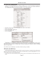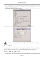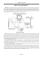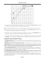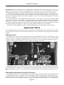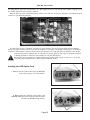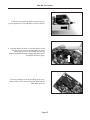
1
Owner’s Manual and UV22HR® License Agreement
v1.1 – March 2003
2-channel portable • 44.1/48/88.2/96 kHz sampling
24-bit A/D Converter with mic/instrument preamp
Mini•Me User’s Guide
Table of Contents
Warnings ...........................................................................................................................4
Registration & Warranty Information ...............................................................................5
Service Information...........................................................................................................5
Declarations of Conformity...............................................................................................6
Licensing & Legal Information ..........................................................................................7
Owner’s record .................................................................................................................7
User’s Installation Notes ...................................................................................................8
About This Manual ............................................................................................................8
The Manual
Table of Contents..............................................................................................................9
Introducing the Mini•Me.................................................................................................11
Front Panel Features
Back Panel Features
Unit Features ..................................................................................................................11
Unpacking .......................................................................................................................13
Operation........................................................................................................................13
Quick Start ......................................................................................................................................................14
Detailed Operation .........................................................................................................14
Analog Input Selector
Line Input
Microphone Input
Instrument Input
Metering..........................................................................................................................................................15
Sample Rate and Resolution Selector
USB Input and Output ....................................................................................................16
Operating System and ASIO Driver Support
Operating Systems currently supported
Macintosh OS 9.x
USB Audio with Sound Manager ....................................................................................................................17
USB Audio with ASIO Driver
Macintosh OS X ..............................................................................................................................................18
Windows 98SE, Me, 2000 and XP
Soft Limit and Push-IT.....................................................................................................20
Using Soft Limit and Push-IT circuits ..............................................................................................................21
Applying the UV22HR Process .......................................................................................22
Outputs ...........................................................................................................................22
AES/EBU
S/PDIF
USB Audio
Analog Output ................................................................................................................................................23
Headphone Out
Application Notes ......................................................................................................23-25
Adjusting Push-It
Adjusting the Microphone Preamp Gain Structure
Installing the USB Option Card
Specifications ..................................................................................................................26
Page 3
Mini•Me User’s Guide
This manual was written by Jim Keller and revised by Richard Elen.
Edited and produced by Richard Elen.
SoftLimit and UV22HR are Registered Trademarks, and Push-IT is a Trademark, of Apogee Electronics
Corporation. All other trademarks are property of their respective holders.
Technology within the Mini-Me may be covered by one or more patents that are the property of Apogee
Electronics Corporation.
Registered User Customer Support:
For customer support, please call (310) 915-1000 and ask for Tech Support,
or email [email protected].
Technical Support is available to registered owners – be sure to return your registration card or use the on-line
registration form at http://www.apogeedigital.com/register.html
Features and specifications subject to change without notice.
© 2000 APOGEE ELECTRONICS CORPORATION
3145 Donald Douglas Loop South
Santa Monica,
California 90405-3210 USA
Tel: +1 310/915-1000
Fax: +1 310/391-6262
Email: [email protected]
Web: http://www.apogeedigital.com/
This manual is copyright ©2002 by APOGEE ELECTRONICS CORPORATION. All rights reserved. Under copyright laws, this manual may not be duplicated in whole or in part without the written consent of Apogee.
Page 4
Mini•Me User’s Guide
Warnings
CAUTION: To reduce the risk of electrical shock, do not remove the cover. No user serviceable parts inside;
refer servicing to qualified personnel. To change the operating voltage or change the firmware EPROM, it is
necessary to remove the cover of the unit. As a result, such operations must be carried out only by technicallyqualified personnel.
WARNING: To reduce the risk of fire or electrical shock, do not expose this appliance to rain or moisture.
This symbol, wherever it appears, alerts you to the presence of uninsulated dangerous voltage inside
the enclosure—voltage that may be sufficient to constitute a risk of shock. Operations indicated with
this symbol should be carried out only by technically-qualified personnel.
This symbol, wherever it appears, alerts you to important operating and maintenance instructions in
the accompanying literature. Read the manual.
Environmental warnings
•
•
•
•
•
•
•
•
•
Never touch the AC plug with wet hands.
Do not use this unit in damp areas or near water.
Avoid damaging the AC plug or cord and potentially causing a shock hazard.
If liquids spill into or onto the Mini•Me , disconnect the power and return to your dealer for servicing.
This unit should only be connected to an AC power supply of the correct voltage. Check with your dealer
if in doubt.
Precautions should be taken so that the grounding or polarization of the AC power is not defeated.
Unplug the AC cord when the unit is unused for long periods of time.
This unit should only be cleaned as recommended by the manufacturer, or damage to the finish may result.
To avoid potential damage to your unit, only use in areas where proper ventilation and moderate temperatures are assured.
Power warning
AC voltage ratings for electrical power vary from area to area. Severe damage to your unit is possible
if your Mini•Me is configured incorrectly for your local power. If in doubt, consult an Apogee dealer. A
label adjacent to the power connector indicates the voltage to which the unit was set on leaving the
factory.
FCC warning
This equipment has been tested and found to comply with the limits for a Class A digital device, pursuant to
Part 15 of the FCC rules. These limits are designed to provide reasonable protection against harmful interference when operated in a commercial environment. This equipment generates, uses, and can radiate radio frequency energy and, if not installed and used in accordance with the instruction manual, may cause
harmful interference to radio communications. Operation of this equipment in a residential area is likely to cause harmful interference, in which case the user will be required to take whatever measures may
be required to correct the interference at his own expense.
Copyright Notice
The Apogee Mini•Me is a computer-based device, and as such contains and uses software in ROMs. This
software, and all related documentation, including this Owner’s Manual, contain proprietary information which
is protected by copyright laws. All rights are reserved. No part of the software and its related documentation
may be copied, transferred, or modified. You may not modify, adapt, translate, lease, distribute, resell for profit or create derivative works based on the software and its related documentation or any part thereof without
prior written consent from Apogee Electronics Corporation, U.S.A.
Page 5
Mini•Me User’s Guide
Registration and Warranty Information
Be sure to register your Mini•Me , either by filling in the enclosed Registration Card or
by completing the on-line registration form at our Web site: http://www.apogeedigital.com/register.html. If you do so, Apogee can contact you with any update information. As
enhancements and upgrades are developed, you will be contacted at the registration
address. Firmware updates are free for the first year of ownership unless otherwise stated.
Please address any inquiries to your dealer or directly to Apogee at:
APOGEE ELECTRONICS CORPORATION, 3145 Donald Douglas Loop South, Santa Monica, CA 90405, USA.
TEL: (310) 915-1000, FAX: (310) 391-6262
email: [email protected]. Web: http://www.apogeedigital.com/
APOGEE ELECTRONICS CORPORATION warrants this product to be free of defects in material and manufacture under normal use for a period of 12 months. The term of this warranty begins on the date of sale to the
purchaser. Units returned for warranty repair to Apogee or an authorized Apogee warranty repair facility will be
repaired or replaced at the manufacturer’s option, free of charge. All units returned to Apogee or an authorized Apogee repair facility must be prepaid, insured and properly packaged. Apogee reserves the right to
change or improve design at any time without prior notice. Design changes are not implemented retrospectively, and the incorporation of design changes into future units does not imply the availability of an upgrade
to existing units.
This warranty is void if Apogee determines, in its sole business judgment, the defect to be the result of abuse,
neglect, alteration or attempted repair by unauthorized personnel.
The warranties set forth above are in lieu of all other warranties, expressed or implied, and Apogee specifically disclaims any and all implied warranty of merchantability or of fitness for a particular purpose. The buyer
acknowledges and agrees that in no event shall the company be held liable for any special, indirect, incidental
or consequential damages, or for injury, loss or damage sustained by any person or property, that may result
from this product failing to operate correctly at any time.
USA: Some states do not allow for the exclusion or limitation of implied warranties or liability for incidental or
consequential damage, so the above exclusion may not apply to you. This warranty gives you specific legal
rights, and you may have other rights which vary from state to state.
Service Information
If the Mini•Me is kept in a clean environment free of excess dust, moisture and heat, it will give years of trouble-free service.
The Mini•Me contains no user-serviceable components: refer to qualified service personnel for repair or
upgrade. Your warranty will be voided if you tamper with the internal components. If you have any questions
with regard to the above, please contact Apogee.
In the event your Mini•Me needs to be upgraded or repaired, it is necessary to contact Apogee prior to shipping, and a Return Materials Authorization (RMA) number will be assigned. This number will serve as a reference for you and helps facilitate and expedite the return process. Apogee requires that shipments be pre-paid
and insured — unless otherwise authorized in advance. IMPORTANT: Any shipment that is not pre-paid or is
sent without an RMA number will not be accepted.
Page 6
Mini•Me User’s Guide
Declarations of Conformity
Declaration of Conformity—FCC
Apogee Mini•Me
This device complies with Part 15 of the FCC Rules. Operation is subject to the following two conditions:
(1) This device may not cause harmful interference, and
(2) This device must accept any interference received, including interference that may cause undesired operation.
This equipment has been tested and found to comply with the limits of a Class B digital device, pursuant to
Part 15 of the FCC Rules. These limits are designed to provide reasonable protection against harmful inteference in a residential installation. This equipment generates, uses and can radiate radio frequency energy and,
if not installed and used in accordance with the instructions, may cause harmful interference to radio communications. If this equipment does cause harmful interference to radio or television reception, which can be determined by turning the equipment off and on, the user is encouraged to try to correct the interference by one or
more of the following measures:
1. Re-orient or relocate the receiving antenna.
2. Increase the separation between the equipment and receiver.
3. Connect the equipment into an outlet on a different circuit from that to which the receiver is connected.
4. Consult the dealer or an experienced radio/TV technician for help.
NOTE: The use of non-shielded cable with this equipment is prohibited.
CAUTION: Changes or modifications not expressly approved by the manufacturer responsible for compliance
could void the user’s authority to operate the equipment.
Apogee Electronics Corporation, 3145 Donald Douglas Loop South, Santa Monica, CA 90405.
Betty Bennett, CEO.
Industry Canada Notice
This Class B digital apparatus meets all requirements of the Canadian Interference-Causing Equipment
Regulations.
Cet appareil numérique de la classe B respecte toutes les exigences du Règlement sur le matérial brouilleur
du Canada.
Declaration of Conformity – CE
Apogee Electronics Corporation hereby declares that the product, the Mini•Me , to which this declaration
relates, is in material conformity with the following standards or other normative documents:
• EN50081-1/EN55022; 1995
• EN50082-1/IEC 801-2, 3, 4; 1992
following the provisions of:
• 73/23/EEC – Low Voltage Directive
• 89/336/EEC – EMC Directive
Declaration of Conformity – Japan
Apogee Electronics Corporation hereby declares that the Mini•Me , to which this declaration relates, is in material conformity with the VCCI Class A standard.
Declaration of Conformity – Australia
Apogee Electronics Corporation hereby declares that the Mini•Me is in material conformity with AN/NZS standard requirements.
Page 7
Mini•Me User’s Guide
Licensing and Legal Information
Carefully read the following legal agreement prior to using the UV22HR process provided in the Mini•Me.
Use of UV22HR constitutes your acceptance of these terms. If you do not agree to the terms of the agreement,
promptly return the Mini•Me and the accompanying items, including written materials and containers to the
location where you obtained them for a full refund.
1. License Grant APOGEE ELECTRONICS CORPORATION (“Apogee”) hereby grants to you, the Purchaser
(either as an individual or entity), a personal, non-transferable, and non-exclusive right to use the UV22HR
Process provided with this license. You agree you will not copy the materials accompanying the Mini•Me. The
material contained in this manual consists of information that is the property of Apogee and is intended solely
for use by the purchasers of the equipment described in this manual. Apogee expressly prohibits the duplication of any portion of this manual or the use thereof for any purpose other than the operation or maintenance
of the equipment described in this manual without the express written permission of Apogee.
2. Copyright You acknowledge that no title to the intellectual property in the Mini•Me is transferred to you.
You further acknowledge that title and full ownership rights to the Mini•Me will remain the exclusive property
of Apogee, and you will not acquire any rights to the UV22HR process except as expressly set forth above.
3. Reverse Engineering You agree that you will not attempt (and, if you are a corporation, you agree to use
your best efforts to prevent your employees and contractors from attempting) to reverse compile, modify,
translate or disassemble the UV22HR Process Software in whole or in part.
4. Customer Remedies Apogee’s entire liability and your sole and exclusive remedy shall be, at Apogee’s
option, either to (a) correct the error, (b) help you work around or avoid the error or (c) authorize a refund or
replacement (at Apogee’s option), so long as the Mini•Me, documentation and all accompanying items are
returned to Apogee according to the instructions on the Warranty Information page opposite, with a copy of
your receipts.
CAUTION
Any changes or modifications not expressly approved by APOGEE ELECTRONICS CORPORATION could void
your authority to operate this equipment under the FCC rules.
OWNER’S RECORD
The serial number is located on the rear panel of the unit. We suggest you record the serial number in the space
provided below. Refer to it whenever you call an authorized Apogee Electronics repair facility or the manufacturer. Please be sure to return your completed warranty card immediately!
Mini•Me
Serial No. ________________
Purchase Date __________________
Factory Firmware Revision ________________
Dealer____________________________________________________
Phone ____________________________________________________
Address ___________________________________________________
Page 8
Mini•Me User’s Guide
User’s Installation Notes
Space left blank for user tracking of factory modifications, option installations, software upgrades, manual revisions/ addenda, internal settings, etc.
About This Manual
This manual was written to help you to use this product to its fullest potential. Although the Mini•Me is inherently simple to operate, it may contain features that may not be obvious from the front panel. Therefore, reading this manual is recommended to unlock the full value of this product.
This manual was also written to prevent misuse of this product. Should you run into a problem when operating the Mini•Me, the solution is hopefully contained in the following pages. We expect that this manual will
serve as the basis of your diagnosis of problems encountered and hope it will be used as such prior to any calls
to technical support at Apogee.
Remember — before calling technical support at Apogee, you must register this product either by sending
in the registration card or by registering on the Apogee Web site (http://www.apogeedigital.com). The technical support specialist will refer to the manual during your call and will expect that you have read it and understand the product to some degree.
If you have any suggestions on how to improve this owner’s manual, please forward them to
[email protected] or fax them to +1-310-391-6262.
Page 9
Mini•Me User’s Guide
This page intentionally left blank
Page 10
Mini•Me User’s Guide
Introducing The Mini•Me
Front Panel
•
•
•
•
•
•
•
•
•
Left and Right Analog line/mic selection and Mic Gain knob.
Input Meter LEDs.
Line input level trim pots.
Soft Limit and Push-IT switches.
Sample rate and resolution selection knob.
Power/+48 volt LED indicator.
Power/+48 volt switch.
Headphone monitor mix knob.
Headphone volume knob.
Rear Panel
•
•
•
•
•
•
Power supply/battery input.
AES/EBU output.
S/PDIF output.
USB Audio connector. (If USB Option Card is installed)
1/8 in Mini headphone jack output.
Left and Right analog input (universal XLR/TRS sockets).
Unit Features
The first converters that Apogee ever made were portable reference units. They rapidly became the choice of
mastering engineers, because of their superb audio quality. Best-loved of early Apogee converter designs was
the AD-1000, with its two channels of mic pre and unparalleled flexibility in the studio or in the field.
The Portable Answer
Now, by popular demand, Apogee has returned to home territory with the release of a new portable 2-channel A/D converter with built-in mic/instrument preamps, featuring a special low-power, wide range supply-voltage design for maximum flexibility – in the studio or in the field.
The Apogee Mini•Me is a completely new design. Its looks recall the AD-1000, with its purple knobs and
sturdy extruded case, but inside is a completely new, 21st-century design. Everything is better, from its 24-bit,
96 kHz sampling capability to its direct computer interfacing via USB – so you can use almost any software you
choose. But this compact unit is not a toy. It delivers true Apogee professional-quality audio performance, from
input to output.
Page 11
Mini•Me User’s Guide
The New Compact Vision
The smooth lines of the Mini•Me front panel begin to tell the story. Left and right input level controls feature a click stop at the far left that activates a preset line/cal level, set with multi-turn trimmers. Accurate LED
indicators between the input level controls give a clear display of available headroom.
Mic/Instrument Preamps
The mic preamps are a high-quality design by the team that created our award-winning and widely praised
Trak2 preamps. And, like the Trak2, the Mini•Me accepts mic, line and instrument-level inputs. Phantom power
is of course provided, and universal XLR/TRS connectors select the instrument input automatically when you
plug in a TRS jack.
Compressor/Limiter
Apogee has long been famed for our Soft Limit process, designed to maximize digital level without overs –
but with the Mini•Me, there’s a major new twist: we’ve added Push-IT – a unique new three-curve stereo compressor/ limiter circuit. It’s ideal when you need extra punch, or require a safety net for the unexpected when
making live recordings. This powerful new circuitry takes Apogee’s dynamics control to a whole new level – from
the people who invented soft limiting for digital conversion.
44.1–96 kHz Sample Rates
A single control selects the sample rate and word length. The Mini•Me’s converters output a full 24-bit signal at any of the standard rates: 44.1, 48, 88.2 and 96 kHz sampling. In addition, select 16- or 20-bit outputs at
44.1 or 48 kHz using Apogee’s industry standard UV22 HR system for word-length reduction.
Apogee UV22HR
If you are producing recording for 16-bit CD – or 20-bits for many DVD-Video projects – then you need a
method of reducing the high resolution 24-bit output of a modern conversion system to 16 or 20 bits. Apogee
UV22HR Encoding – the latest and most powerful development of Apogee’s original UV22 process – is an
entirely different approach to word-length reduction. UV22HR does its job without sonic compromise, and without adding a sound of its own, preserving the sound stage and tonal balance of the original high-resolution
source. The effects are even audible on original 16-bit recordings.
UV22HR Encoding adds an inaudible, algorithmically-generated concentration of energy around 22 kHz.
Technically, it’s known as “Sub-Nyquist-band dither”. Much as the bias on an analog tape recorder smooths out
magnetic tape recording non-linearities, UV22HR silently captures resolution beyond 20 bits on a standard, 16bit CD. In addition, this inaudible carrier smooths the rough edges of even the most inexpensive CD player or
external converter. UV22HR makes your recordings sound better on all listening systems.
The truly unique statistical properties of UV22HR guarantee a constant white noise floor, very similar in character to analog tape noise, no matter what the input source. If you listen to a UV22HR encoded recording, you
can hear a stable, accurate sound stage and faithful tonal balance more than 24dB into the noise – just as you
do on analog tape.
Yet the UV22HR’s low audible noise floor sits at the theoretical limit for a 16-bit or 20-bit system. Nothing is
lost – but a great deal is gained. In listening test after listening test, engineers and reviewers alike choose UV22
over all other systems. Many thousands of CD titles have already been mastered using Apogee UV22 and
UV22HR processors. Apogee’s process is today in use in the vast majority of US mastering houses, and it is
estimated that as many as 80% of the hit records mastered in the United States today utilize the system. And
while others have tried to imitate UV22HR, none have succeeded in delivering its superior performance.
Plug and play with Optional USB Card
The Mini•Me’s USB interface carries two channels of audio at up to 24-bits and 48 kHz sampling, from the
Mini•Me to the computer and back again for monitoring. Using an operating system that supports USB Audio
Devices (including Windows 98SE, Me, 2000 and XP, and Macintosh OS 9.x and 10.x), simply select the option
in your recording application’s preferences. ASIO drivers are also supplied for reduced latency.
Even if you get the sample rates mismatched between the Mini•Me and your computer, the unit will convert
sample rates automatically. And if you select, for example, 24-bit on the unit and 16-bit on the computer,
UV22HR will automatically be applied to the signal sent to the USB port (44.1/48 kHz sampling only).
Page 12
Mini•Me User’s Guide
Standard Interfaces
The Mini•Me includes AES/EBU (XLR) and S/PDIF (RCA/coaxial) outputs which are available simultaneously,
clocked by a high-stability reference crystal oscillator, making the Mini•Me an ideal master clock.
Direct/Return Mix Monitor
A comprehensive mono/stereo monitor section allows you to balance the direct sound you’re recording with
audio returned via the USB port.
Battery Power
The Mini•Me ’s low power consumption makes it ideal for battery operation. The standard power unit included) supplies 12v DC at up to 1.25A (connector is center-positive), but the unit can be run on sources from 6 to
14 volts DC. Several suitable battery packs are available from third-party suppliers.
Unpacking
Your Mini•Me is packed in a foam lined shipping container. Please be sure to save the container and foam for
any future shipments of the unit.
Included Accessories
The following accessories are shipped with the Mini•Me .
•
•
•
Universal 12-volt power supply
Operation manual (this document)
Warranty Card
Optional Accessories
Carrying Case
A carrying case is available, complete with strap and extra pockets for batteries (optional), tapes, etc. The
carrying case is made of rugged black nylon, contains a main pouch for the Mini•Me that features protective
flaps with zippers to allow cable access to the rear panel. The extra pockets are ideal for stowing other options
or personal items.
USB Option Card
The USB Option Card may be retrofitted on any Mini-Me delivered without this option. Please refer to the
“Application Notes” section of this manual for installation instructions.
Operation
Your Mini•Me is shipped ready to use in conjunction with AES/EBU and S/PDIF digital systems. In order to
use the Mini•Me with USB Audio, you must first download the driver from our website at
http://www.apogeedigital.com/usb.
All Apogee products spend at least two days ‘burning-in’ at the factory before delivery. This burn-in procedure involves powered operation at elevated temperatures to isolate units that would possibly fail due to component defects.
We recommend that you read this entire manual to get the most out of your new Mini•Me .
Page 13
Mini•Me User’s Guide
Quick Start
Connect left and right analog inputs to the rear XLR or 1/4 in connectors. These inputs are to the far right
as you look at the rear panel (If necessary, refer to rear panel diagram on p.11 for location. See below for detail
on different analog sources and which input connection should be used.)
Connect the digital output from the AES/EBU male XLR connector, S/PDIF female coaxial connector, or USB
connector on the rear panel to your desired recording device. (See USB Audio section overleaf for detailed
information on USB Audio operation. Refer to rear panel diagram for location of connections.)
Connect the power cable from the supplied power adapter, or from your optional battery pack, to the power
input on the rear panel of the unit. (Refer to rear panel diagram for location.)
Set the front panel power switch to the center “On” position. (See front panel diagram, p.11, for location.)
Select the desired sample rate and resolution on the “Sample Rate” knob. (See front panel diagram for location.)
Set the left and right input knobs to line or mic level, depending on analog source. For line level operation,
rotate the knobs fully counter-clockwise and set your level with the multi-turn trimpots. (See front panel diagram for location. See below for detail on mic/line level operation and level settings.)
Your Mini•Me should now be supplying digital audio, and input activity level will be shown on the level/headroom meters. You can monitor this signal through the headphone outputs.
Detailed Operation
Analog Input Selector
There are three different types on analog input available on the Mini•Me : Microphone (with switchable +48
volt phantom power), line level, and instrument (Hi-Z) input. All three variations of input share the same universal XLR/TRS connector. There are two of these connectors on the rear panel, one each for left and right
channel.
Line Input
To select line level input, turn the input knob for the appropriate channel to its detent position – fully counter
clockwise. When the input knob is in this position, line input level is adjusted with the recessed “cal/line” multiturn trim pots on the front panel. Turning the pots clockwise will increase the gain. It is important to note that
adjusting these pots will change the factory calibration of the unit for line input mode. The factory calibration
of +4dB equals –16dBFs (see “Meters” section) is suitable for most line input levels
Microphone Input
To select microphone inputs for the Mini•Me , the input knob must be switched out of its detent line input
status by turning the knob clockwise. Once the knob is switched out of line level input, it will control gain supplied to the incoming microphone signal. Turning the knob clockwise will increase the gain. Up to 65dB of gain
is available.
To turn on phantom power (+48 volts) for use with condenser microphones, press and hold the power switch
on the front panel all the way to the right (in its momentary position) for two seconds. The green power LED
will change to red to indicate that phantom power is enabled. When phantom power is on, +48 volts will be
supplied to any channel that is in microphone input mode. Switching a channel to line input or inserting a 1/4
inch jack into a channel will bypass phantom power only for that channel. Switching both left and right input
knobs to line input mode will turn off phantom power.
Instrument Input
Instrument input (Hi-Z) mode is automatically selected when a 1/4 in jack is inserted into the analog input
jack on the rear panel. If the Mini•Me is in line input mode, then the level can be adjusted with the recessed
“cal/line” adjustment pot. If the Mini•Me is in microphone input mode, then the level can be adjusted with the
input knob. When using the Hi-Z inputs, we recommend that levels be set with the input knobs as opposed to
the recessed “cal/line” pots. This will provide quick level adjustment and not alter the level/calibration of the
line inputs.
Page 14
Mini•Me User’s Guide
*Note: When sending a line input into the Mini•Me, it is important not to use the 1/4 in inputs, as these
inputs have additional gain, as is required for instrument inputs such as guitars or keyboards. If your
source for line input is 1/4 inch, we suggest a 1/4 in to XLR cable to enable proper connection to the
Mini•Me.
Metering
The front panel metering LEDs indicate the level of the input signal after A/D conversion. The numbers by
each LED (-40, -12, and -2) represent the digital headroom in units in what is referred to as digital full-scale
(dBFs). To get a clear picture of how digital levels relate to analog levels, see the figure below.
The red “over” LED’s will illuminate when three consecutive full-scale samples are output by the A/D converter chip.
Sample Rate and Resolution Selector
The Mini•Me is capable of sample rates of 44.1 kHz, 48 kHz, 88.2 kHz and 96 kHz. All of these sample rates
are available at 24-bit resolution. At sample rates of 44.1 kHz and 48 kHz, the 24-bit word length may reduced
down to 16- or 20-bit resolution via Apogee’s UV22HR dithering algorithm.
The unit also features digital black settings at all four sample rates. Choosing one of these settings will supply sync information only on all digital outputs. No digital audio will be output from the Mini•Me in these
modes.
To choose a sample rate/resolution combination, use the “Sample Rate” knob on the front panel. This knob
has twelve positions, each of which stops at positions similar to the hours on a clock. Sample rates are silkscreened in black, while the resolution has a colored background silk-screen.
Examples:
•
•
•
If you need to record with a 44.1 kHz sample rate and 16-bit resolution, then set the “Sample Rate” knob
to the one o’clock position.
If you need to record with a 88.2 kHz sample rate and 24-bit resolution, then set the “Sample Rate” knob
to the ten o’clock position.
To use the Mini•Me as a clock source only for 48 kHz recording, set the “Sample Rate” knob to the six
o’clock position for 48 kHz digital black.
Page 15
Mini•Me User’s Guide
USB Input & Output
A Mini•Me equipped with the USB Option Card offers digital I/O for use with computer operating systems
that support USB Audio devices. The audio can be handled in the operating system in different ways. Refer to
your platform and OS below for detailed information on setup options for the Mini•Me.
The Mini•Me also offers a unique feature that enables the unit to run at a different sample rate and bit depth
than the computer recording software. The USB Audio I/O section of the Mini•Me follows the sample rate
and resolution settings on the computer, while the AES and S/PDIF outputs follow the settings of the “sample rate” knob on the front panel.
For example, this can be used to send a 16-bit/44.1 kHz signal out of the AES output to a CD burner while
simultaneously sending a 24-bit/48 kHz signal out of the USB Audio port to the computer. In this case, the analog inputs are converted at 44.1 kHz and sent through UV22HR, to dither the AES and S/PDIF outputs to 16bit. The USB Audio section receives the 44.1 kHz signal before the dithering process, where it is still a 24-bit
signal. The data is processed with a sample rate converter to derive a sample rate of 48 kHz. The result is a 24bit/48 kHz signal that is sent out the USB port to the computer. The sample rate selction knob on the front of
the Mini•Me will be set to 16-bit /44.1 kHz, while the settings in the computer will be 24-bit/48 kHz.
Another example could be the ability for the Mini•Me to send a 24-bit/96 kHz signal out of the AES port,
while at the same time sending a 16-bit/44.1kHz signal into a DAW via USB. In this instance, set the sample rate
knob on the front panel of the Mini•Me to 24-bit/96 kHz and set the computer to 16-bit/44.1 kHz.
When the computer is set to 16-bit, the Mini•Me sends the USB Audio signal through UV22HR for word
length reduction before it is output to the computer.
The basic concept is that the Mini•Me AES and S/PDIF outputs will always follow the front panel setting, while the USB Audio outputs will always follow the settings on the computer.
For minimal chances of error in recording, we recommend that the computer settings for sample rate are the
same as that of the Mini•Me front panel settings.
Connect the Mini•Me to the computer with a USB cable.
IMPORTANT: The Mini•Me should be plugged directly into a USB port on the computer. It is not
recommended to plug the Mini•Me into a USB port on the keyboard or into a USB hub.
Operating System and ASIO Driver Support
The Apogee Mini•Me can operate via USB in one of two ways: by using the operating system’s support for
USB Audio, and via an ASIO driver for the appropriate operating system. The functionality of these two
approaches varies from one operating system to another, but in general we recommend the use of the ASIO
driver where available, especially in the case of Windows. Software driver development and OS support are
both continuous processes, and support will develop over time. For the latest drivers and information, visit
the Apogee web site’s USB page at http://www.apogeedigital.com/usb/
Operating Systems Currently Supported
As of August 2002, the following operating systems are completely or partially supported, either directly by
the OS or via the ASIO driver:
Macintosh OS 9.1 and later
Macintosh OS X (10.1.x and later)
Windows 98 Second Edition (98SE)
Windows Millennium Edition (Me)
Windows 2000
Windows XP
Macintosh OS 9.x
For Macintosh OS 9.1 and later, the Mini•Me can send and receive USB Audio through Apple’s Sound
Manager or via the custom USB Audio ASIO driver written for the Mini•Me.
Page 16
Mini•Me User’s Guide
USB Audio with Sound Manager
•
Having connected the Mini•Me to your computer via USB, turn it on. To insure that the Mac recognizes the
Mini•Me, go to the Apple menu and choose “Apple System Profiler”. Click on the “Volumes and Devices”
tab. The Mini•Me should show up labeled “Apogee” as one of the USB devices.
•
•
•
•
•
Open the “Sound” Control Panel (in the Apple menu under “Control Panel”).
Click on the “Input” tab.
Choose “External Mic… USB Audio”
Click on the “Output” tab.
Choose “USB Audio”
The Mini•Me is now configured for use with your recording software as a “Sound Manager” option. In your
recording application, open the hardware driver preferences and select “Sound Manager”. Note that different
applications will label this option in different ways. Consult your application’s manual for details on selecting
input and output drivers.
Note: When using Sound Manager, only 16-bit, 44.1 kHz recording is available.
USB Audio with ASIO Driver
The Apogee USB ASIO Driver for Macintosh OS 9.x consists of two parts: an extension that is placed in the
Extensions folder and an ASIO Driver that is placed in the ASIO folder of the recording application. You can
download these items from the Apogee web site.
• UnStuff the archive and manually drag and drop the two items to their destinations. Now restart your computer.
Page 17
Mini•Me User’s Guide
•
•
•
Connect the Mini•Me to the computer with a USB cable.
Power on the Mini•Me. To ensure that the Mac recognizes the Mini•Me, go to the Apple menu and choose
“Apple System Profiler”. Click on the “Volumes and Devices” tab. The Mini•Me should show up labeled
“Apogee” as one of the USB devices.
In your application, select the audio hardware preferences. Exactly what this looks like will depend on the
application; the example shown here is from Logic.
Bring up the control panel (by clicking the button in this case) and you will see the following.
Note that drivers are continually being revised and updated to provide better performance, and occasionally additional features. Visit http://www.apogeedigital.com/usb/ regularly for updates. Registered
users will receive notification of updates via email.
Macintosh OS X
Beginning with version 10.2.3, the MiniMe is natively supported in OS X. No drivers are required; simply
connect the MiniMe via USB, and it will appear as an interface option in all CoreAudio compatible applications.
For certain applications, it may be necessary to configure the Audio Midi utility included with OS X.
Windows 98SE, Me, 2000 and XP
Note that there are some limitations with OS support for the Mini•Me under Windows operating systems.
In particular, playback does not operate correctly with the native Microsoft drivers. Recording operates
Page 18
Mini•Me User’s Guide
correctly, but note that under Windows Me, the built-in drivers do not support 24-bit recording.
We strongly recommend the use of the Windows Mini•Me ASIO driver. The same driver is utilized for all supported Windows versions. This driver offers operating system-wide support for the Mini-Me, allowing it to function correctly even with applications that do not use ASIO.
•
Download the driver from the Apogee web site, expand the ZIP archive to your hard drive, and locate and
double-click on the setup application. You will see a welcome screen; follow the instructions to complete
installation. At the end of the installation process, you will be asked to restart your computer.
•
If you are installing new drivers over previous ones, the installer will inform you of this fact and will offer
to remove the old drivers for you (recommended) or let you do it yourself (advanced users only).
You will now be able to access the Mini•Me for input and/or output via your application. Exactly how this
appears will vary – see the example below from Cubase to get the general idea.
Additional support is being developed. See http://www.apogeedigital.com/usb/ for more information.
Page 19
Mini•Me User’s Guide
Soft Limit and Push-IT™
Soft Limit is an analog process that acts as a guard against digital ‘overs’ that can result from high-level transients in the incoming audio signal. When enabled, Soft Limit will round out peaks in the incoming signal in order
to eliminate the undesirable effects of clipping the A/D converter chip. This rounding will begin on peaks at
about –4dBFs and gradually smooth them out up to 0dBFs in order to safeguard the audio signal. This process
will not only eliminate digital ‘overs’, but it will also help to get a few extra dB of gain to tape or disk. See the
illustration below for a visual representation of how this circuit works.
Push-IT is a unique gain control circuit consisting of a compressor and limiter that are integrated with Soft
Limit. All compressors and limiters adjust gain and are controlled by a detection circuit known as a sidechain.
Every sidechain has a certain response time, and as a result it is possible for occasional fast transients to evade
the limiting action. When used with Push-IT’s limiter, Soft Limit smoothes out any transients that may slip by the
limiter’s response time. You have the ability to chain this limiter with either of the two different Push-IT compression circuits. When used, Push-IT provides significant extra “punch” and gives the user almost total security from overloading the digital outputs.
The main differences between the two compression surves are the attack and release times. These parameters are adaptive and adjust according to the characteristics of the signal. Compression curve number one has
much quicker attack and release times. This circuit will lend itself well to percussive instruments, acoustic guitars, and sources with fast attack.
Compression curve number two has slower attack and release times. This circuit is better suited for bass guitar and vocals, which tend to have slower transient peaks.
The graph below illustrates the various compression and limiting curves generated by the combination of
Soft Limit and Push-IT. Soft Limit is engaged by the three-position toggle switch in the upper center of the front
panel. This is labeled “OFF” to the left – neither Soft Limit (SL) nor Soft Limit + Compression (SLC) enabled;
“SL” for the center position – Soft Limit only; and “SLC” to the right – Soft Limit + Compression (SLC) enabled.
In the SLC position, the lower “Curve” switch is used to select curve 1, 2 or 3.
Page 20
Mini•Me User’s Guide
3
(curve starts at –14 on the left axis) This shows the response curve of SLC setting Compression 3. Top switch
in far right “SLC” position, bottom switch far right in curve “3” position.
off (curve runs from the origin, bottom left, to +0/-0) Circuit bypassed. Top switch in far left “off” position.
SL (curve runs from the origin to +2/-0) This shows the response curve of Soft Limit only. Top switch in center “SL” position. The bottom switch position is not relevant.
2
(curve starts at -25.5 on the left axis) This shows the response curve of SLC setting Compression 2. Top
switch in far right “SLC” position, bottom switch in middle curve “2” position.
1
(curve starts at the origin and exits right at about -1.5 dBFS) This shows the response curve of Soft
Limit/Limit 1 circuit. Top switch in far right “SLC” position, bottom switch in far left curve “1” position.
Using Soft Limit and Push-IT Circuits
Soft Limit and Push-IT settings are controlled by the two switches in the middle of the front panel (see front
panel diagram for location.)
Soft Limit: To turn on Soft Limit only, flip the top switch to the middle “SL” (Soft Limit) position. See the
graph above for the curve that corresponds to this setting.
Soft Limit/Limit 1: To use “Soft Limit” in conjunction with the Push-IT limiter, flip the top switch to the “SLC”
(Soft Limit and Compression) position. With the top switch in this position, the bottom switch’s function will be
enabled to select one of the three available Push-IT settings. For Soft Limit/limit, set this switch to the far left
curve “1” setting. See the graph above for the curve that corresponds to this setting.
Soft Limit/Limit/Compression 2: To use the first compression setting in addition to the Soft Limit/limit circuit, set the top switch to the far right “SLC” position and the bottom switch to the center curve “2” setting.
See the graph above for the curve that corresponds to this setting.
Soft Limit/Limit/Compression 3: To use the second compression setting in addition to the Soft Limit/limit
circuit, set the top switch to the far right “SLC” setting and the bottom switch to the far right curve “3” setting. See the graph above for the curve that corresponds to this setting.
Note that when the top switch is in the “SL” position, the bottom switch is disabled because Push-IT is not
active. When the top switch is in the “off” position, both circuits are bypassed. See page X? for advanced details
on adjusting the PushIT circuit.
Page 21
Mini•Me User’s Guide
Applying the UV22HR Process
UV22HR Encoding is best applied as the final step in the signal chain before the actual mastering device.
Using the Mini•Me as the A/D converter to capture an analog mix to digital for Compact Disc, for example, you
would set the word length to 16 bits.
Notes
•
•
•
•
Because UV22HR is essentially a “once only” process, we do not recommend that you use it more than once
on a signal. Multiple passes through the UV22HR process could degrade the noise floor of the system at
the upper frequencies and produce artifacts.
Recordings to be used in a sample or sound effects disc can be UV22HR encoded if pitch shifting is not likely to be employed, or if pitch shifting upward only is to be used. Pitch shifting downward on processed signals risks making the normally ultrasonic UV22HR energy concentration audible.
You can use UV22HR in conjunction with a wide range of both lossy and lossless compression technologies
used in DVD mastering, such as Dolby AC-3, DTS, and MLP (Meridian Lossless Packing). In addition, UV22HR
is a very useful technique when used in conjunction with Internet audio delivery systems such as ‘MP3’
(MPEG1 Layer III), Real Audio, QuickTime and other systems, where the ability of UV22HR to maintain highresolution quality and detail at the 16-bit level means smaller, better-sounding files and streaming audio signals, offering more effective use of available bandwidth.
As maximizing word length is generally regarded as more important than increasing sample rate, there is
little if any need to provide word-length reduction from 24 bits at sample rates above 48 kHz: in virtually all
cases, where high sample rates are available, so is 24-bit operation. For this reason, we do not provide
UV22HR operation at high sample rates. This policy may be revised if there is sufficient demand.
Outputs
Digital Outputs
AES/EBU: The industry standard AES/EBU (Audio Engineering Society/European Broadcast Union) format. Two
channels of audio data as well as sync information are carried in the same cable. Simply connect the AES output of the Mini•Me to the AES input of the receiving device. Set the receiving device to ‘digital in’. If the receiving device does not automatically switch its sync source to digital in, manually select the AES input as its source.
The AES output is capable of what is commonly referred to as “single-wire” operation at higher sample
rates. That is, at 88.2 and 96 kHz, the single AES output on the rear panel of the Mini•Me will output both left
and right channels. This differs from the older AES format for high speeds, which is referred to as “double-wire”
or “double-wide”. These “double-X” formats required two AES connectors for 88.2K and 96K transfer, essentially using one connector for each channel, and are now generally obsolete.
S/PDIF: S/PDIF (Sony/Philips Digital Interface Format) is a popular digital interface format found on virtually all
DAT recorders and many pro and semi-pro pieces of equipment. Like AES/EBU, two channels of audio data as
well as sync information are carried in the same cable. Simply connect the S/PDIF output of the Mini•Me to the
S/PDIF input of the receiving device. Set the receiving device to ‘digital in’. If the receiving device does not
automatically switch its sync source to digital in, manually select the S/PDIF input as its source.
The S/PDIF output is also capable of single-wire operation at higher sample rates.
USB Audio: The Mini•Me offers USB Audio digital output for use with computer operating systems that support USB Audio devices. The audio can be handled in the operating system in different ways. Refer to your platform and OS on page X? for detailed information on setup options for the Mini•Me. Remember, even if you get
the sample rates mismatched between the Mini•Me and your computer, the unit will convert sample rates automatically. And if you select, for example, 24-bit on the unit and 16-bit on the computer, UV22HR will automatically be applied to the signal sent to the USB port (44.1/48 kHz sampling only).
Once you’ve followed the setup procedure on page X? for the Mini•Me to receive USB Audio from the computer, you’re computer will be set up to receive USB Audio from the Mini•Me.
Page 22
Mini•Me User’s Guide
Analog Output
Headphone Out: The headphone section of the Mini•Me is designed to offer flexible monitoring of the recording process. This output is a 1/8 inch mini headphone jack on the rear panel. You have the ability to monitor the
analog inputs (before A/D conversion), the USB Audio return from the computer, or a mix of both signals.
To monitor the inputs, turn the “Mix” knob on the front panel fully counter clockwise to the “Direct” position. To monitor the USB Audio return from the computer, turn the knob fully clockwise to the “USB” position.
This knob is designed to blend the two signals together in order to mix direct and USB signals for the headphone monitor output.
Another useful feature of the headphone monitoring section is the ability to switch the direct audio signal
output from a stereo to a mono signal. To toggle between mono and stereo, simply push in and release the
“Mix” knob. It is handy to use the mono setting when monitoring the direct signal of one channel, as it allows
the signal to play from both left and right sides of the headphones. This mono setting only affects the direct
audio signal feeding the headphone outputs; the digital outputs and USB I/O are not affected.
The volume for the headphone output is the knob labeled “Mon” on the far right of the front panel.
Application Notes
The following adjustments require the removal of the top panel of the Mini•Me. Unscrew and remove the upper
pair of hex bolts from the front and rear panels and lift the cover off vertically to expose the main circuit board
asembly.
Adjusting Push-IT
The ratios for the compressors in the PushIT circuit are user adjustable. There are two small trim pots on the
main circuit board in positions R165 and R166 (see picture below for detail of location). You’ll notice that R166
is labeled “Preset 2” and R165 is labeled “Preset 3”. The “Preset 2” trim pot adjusts the settings for curve “2”
compressor circuit while the “Preset 3” trim pot adjusts the settings for curve “3”.
With these trim pots, you can adjust the ratio from 1:1 to 1:3. Each trim pot has the same range; the difference between the two compressors is in the time constant. With the trim pot turned counter clockwise all the
way, the compressor ratio is 1:1 – essentially turned off. With the trim pot set all the way clockwise, the ratio is
1:3.
Adjusting the Microphone Preamp Gain Structure
The Mini-Me includes sets of internal jumpers that adjust the gain structure of the microphone preamp (line
and instrument inputs are not affected). The standard setting allows for maximum gain – permitting the use of
low-output microphones such as ribbon types, or recording very quiet sounds; while the lower-gain setting minimizes the chances of overloading the mic input stage in very high sound pressure levels – for example while
Page 23
Mini•Me User’s Guide
recording drums, explosive sound effects, etc. We suggest that you only change these jumper settings if you
are actually experiencing overload conditions.
Remove the top cover as described above. Now look to the rear of the unit, adjacent to the universal input
connectors (see illustration below).
You will see four pairs of jumpers, two pairs for each channel. You can configure each channel independently if you wish, but be sure to move all four jumpers for a channel. The jumpers each plug on to three-pin
connectors. Each jumper connects the frontmost and center pin for high gain (factory default) or the center
and rearmost pin for reduced gain. To reposition a jumper, grasp it with a pair of tweezers and pull
it directly upwards to remove it, then replace it over the desired pins.
Be sure that all four jumpers for a given channel are set the same way (all to the front or all to the
rear). Any other jumper positions will produce undefined results.
Installing the USB Option Card
1. Remove the two TOP screws from the Mini•Me
front panel, using a 1/16” hex wrench.
2. Remove the two TOP rear panel screws, and
LOOSEN ONLY the bottom two rear panel screws
and the four XLR Mounting Screws.
Page 24
Mini•Me User’s Guide
3. Pull the rear panel back (without removing it) to
provide clearance for the USB Option Card connecter.
4. Insert the USB Connecter (on the USB Option Card)
into the square cutout of the Mini•Me rear panel,
ensure that connector pins under the card are
properly aligned (indicated at right), and gently press
the Option Card into place.
5. Secure the Option Card by installing the two provided screws in the locations indicated. Re-install the
Mini•Me Top Cover.
Page 25
Mini•Me User’s Guide
Specifications
Inputs
Analog Inputs (two 3-pin/1/4 in TRS connectors on rear panel)
Line Level:
–10dBu (consumer) to +4dBu
Microphone Level:
Mic amp gain range 12-65 dB.
Instrument Level:
Instrument input impedance is 2.2MΩ.
Digital Input (USB connector on rear panel)
USB
USB Audio from computer available at resolutions up to 24-bit and sample rates up to 48 kHz.
Outputs
Analog Output
Headphones (1/8 in mini stereo headphone jack on rear panel):
0.3 Watts/Channel RMS out.
Digital Outputs
AES/EBU (male XLR on rear panel):
Sample rates from 44.1-96 kHz
Resolutions of 16, 20 and 24-bit.
(16 and 20 bit resolutions available only at 44.1 and 48 kHz sample rates)
Single-wire operation at 88.2 and 96 kHz
Digital black
S/PDIF (female coaxial connector on rear panel):
Sample rates from 44.1–96 kHz.
Resolutions of 16, 20 and 24-bit.
(16 and 20 bit resolutions available only at 44.1 and 48 kHz sample rates)
Single-wire operation at 88.2 and 96 kHz.
Digital black
USB Audio (USB connector on rear panel):
For use with a USB-capable computer
running a supported operating system and software application.
Sample rates up to 48 kHz.
Resolutions up to 24-bit.
Dynamic range
105 dB
THD+Noise
–94 dB
Sample rates
44.1–96 kHz ±10%
Freq. Response
20 Hz – 20 kHz ±0.2 dB @ 44.1 kHz Fs
Inputs
Mic/line (XLR), instrument (TRS) (universal skts)
Min/Maximum input level (CAL/LINE)
–6/28 dBu
Mic amp gain range
12–65 dB
Mic input impedance
1.2 kΩ
Line input impedance
10 kΩ
Instrument input impedance (1/4in connector) 2.2MΩ
Digital interfaces
USB Audio I/O, AES/EBU, S/PDIF
Headphone monitor
0.3W/channel RMS out, 1/8in jack
Power input 6-16 v dc, 5.5W
Power supply
External, universal voltage in, 12v dc out
USB power
Derived from interface
Size (w x d x h)
5.4in x 9.8in x 1.5in
Weight
2 lb
Page 26