1
Operation/Reference Guide
NXB-KNX
NetLinx KNX Interface
Control System Accessories
Initial Release: 5/15/2008
AMX Limited Warranty and Disclaimer
This Limited Warranty and Disclaimer extends only to products purchased directly from AMX or an AMX Authorized Partner which
include AMX Dealers, Distributors, VIP’s or other AMX authorized entity.
AMX warrants its products to be free of defects in material and workmanship under normal use for three (3) years from the date of
purchase, with the following exceptions:
•
Electroluminescent and LCD Control Panels are warranted for three (3) years, except for the display and touch overlay components are warranted for a period of one (1) year.
•
Disk drive mechanisms, pan/tilt heads, power supplies, and MX Series products are warranted for a period of one (1) year.
•
AMX lighting products are guaranteed to switch on and off any load that is properly connected to our lighting products, as long
as the AMX lighting products are under warranty. AMX also guarantees the control of dimmable loads that are properly connected to our lighting products. The dimming performance or quality there of is not guaranteed, impart due to the random combinations of dimmers, lamps and ballasts or transformers.
•
AMX software is warranted for a period of ninety (90) days.
•
Batteries and incandescent lamps are not covered under the warranty.
•
AMX AutoPatch Epica, Modula, Modula Series4, Modula CatPro Series and 8Y-3000 product models will be free of defects in
materials and manufacture at the time of sale and will remain in good working order for a period of three (3) years following the
date of the original sales invoice from AMX. The three-year warranty period will be extended to the life of the product (Limited
Lifetime Warranty) if the warranty card is filled out by the dealer and/or end user and returned to AMX so that AMX receives it
within thirty (30) days of the installation of equipment but no later than six (6) months from original AMX sales invoice date. The
life of the product extends until five (5) years after AMX ceases manufacturing the product model. The Limited Lifetime Warranty
applies to products in their original installation only. If a product is moved to a different installation, the Limited Lifetime Warranty
will no longer apply, and the product warranty will instead be the three (3) year Limited Warranty.
All products returned to AMX require a Return Material Authorization (RMA) number. The RMA number is obtained from the AMX
RMA Department. The RMA number must be clearly marked on the outside of each box. The RMA is valid for a 30-day period. After
the 30-day period the RMA will be cancelled. Any shipments received not consistent with the RMA, or after the RMA is cancelled, will
be refused. AMX is not responsible for products returned without a valid RMA number.
AMX is not liable for any damages caused by its products or for the failure of its products to perform. This includes any lost profits, lost
savings, incidental damages, or consequential damages. AMX is not liable for any claim made by a third party or by an AMX Authorized Partner for a third party.
This Limited Warranty does not apply to (a) any AMX product that has been modified, altered or repaired by an unauthorized agent or
improperly transported, stored, installed, used, or maintained; (b) damage caused by acts of nature, including flood, erosion, or earthquake; (c) damage caused by a sustained low or high voltage situation or by a low or high voltage disturbance, including brownouts,
sags, spikes, or power outages; or (d) damage caused by war, vandalism, theft, depletion, or obsolescence.
This limitation of liability applies whether damages are sought, or a claim is made, under this warranty or as a tort claim (including
negligence and strict product liability), a contract claim, or any other claim. This limitation of liability cannot be waived or amended by
any person. This limitation of liability will be effective even if AMX or an authorized representative of AMX has been advised of the
possibility of any such damages. This limitation of liability, however, will not apply to claims for personal injury.
Some states do not allow a limitation of how long an implied warranty last. Some states do not allow the limitation or exclusion of incidental or consequential damages for consumer products. In such states, the limitation or exclusion of the Limited Warranty may not
apply. This Limited Warranty gives the owner specific legal rights. The owner may also have other rights that vary from state to state.
The owner is advised to consult applicable state laws for full determination of rights.
EXCEPT AS EXPRESSLY SET FORTH IN THIS WARRANTY, AMX MAKES NO OTHER WARRANTIES, EXPRESSED OR
IMPLIED, INCLUDING ANY IMPLIED WARRANTIES OF MERCHANTABILITY OR FITNESS FOR A PARTICULAR PURPOSE. AMX
EXPRESSLY DISCLAIMS ALL WARRANTIES NOT STATED IN THIS LIMITED WARRANTY. ANY IMPLIED WARRANTIES THAT
MAY BE IMPOSED BY LAW ARE LIMITED TO THE TERMS OF THIS LIMITED WARRANTY. EXCEPT AS OTHERWISE LIMITED
BY APPLICABLE LAW, AMX RESERVES THE RIGHT TO MODIFY OR DISCONTINUE DESIGNS, SPECIFICATIONS, WARRANTIES, PRICES, AND POLICIES WITHOUT NOTICE.
Table of Contents
Table of Contents
Overview ............................................................................................................1
Product Specifications ............................................................................................. 1
Installation ..........................................................................................................3
Wiring and Connections............................................................................................ 3
Ethernet 10/100 Base-T RJ-45 Wiring Configuration ................................................ 3
PoE (Power Over Ethernet) ............................................................................................. 4
KNX Connector......................................................................................................... 4
Configuration .....................................................................................................5
Overview .................................................................................................................. 5
Determining the IP Address of the NXB-KNX........................................................... 5
Bonjour (Zero-Configuration) Client ................................................................................ 5
Accessing the WebConsole ............................................................................................. 6
Admin Menu ............................................................................................................. 6
Security Settings ....................................................................................................... 7
Enable / Disable Security Settings ................................................................................. 7
Login Information............................................................................................................ 7
Logging Into the Configuration Manager (With Security Enabled).................................. 8
IP Settings................................................................................................................. 8
Port Settings............................................................................................................. 9
Clock Manager........................................................................................................ 10
Clock Manager - Mode Manager................................................................................... 10
Clock Manager - Daylight Savings ................................................................................. 11
Clock Manager - NIST Servers ....................................................................................... 12
Application Upgrade............................................................................................... 13
Current Application Information ................................................................................... 13
Browse for new Application Upload File ....................................................................... 13
Firmware Upgrade.................................................................................................. 14
Current Firmware Information....................................................................................... 14
Browse for new Firmware Upload File .......................................................................... 14
Programming - Telnet Commands ....................................................................15
Overview ................................................................................................................ 15
Establishing a Terminal Connection Via Telnet ....................................................... 15
Terminal Commands ............................................................................................... 16
NXB-KNX NetLinx KNX Interface
i
Table of Contents
ii
NXB-KNX NetLinx KNX Interface
Overview
Overview
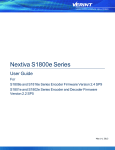
The NetLinx NXB-KNX interface (FG2031-01) allows AMX NetLinx Integrated Controllers the ability to
control, integrate and communicate with homes and buildings that utilize the KNX communication protocol.
KNX is the world’s first open, royalty-free, and platform independent standard for home and commercial
building control.
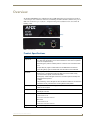
(front)
(rear)
FIG. 1 NXB-KNX Interface
Product Specifications
NXB-KNX Specifications
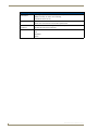
Front Panel
Components:
• Status LED (green): Blinks once a second to indicate that the unit has powered up.
Any state other than blinking once a second indicates the unit is either not powered,
or has not completed boot up.
• KNX LED (green): Solid on indicates power is on and the unit is connected to KNX
bus.
• Output LED (red): Lights to indicate traffic from the NXB-KNX to the KNX bus.
• Input LED (yellow): Lights to indicate traffic from the KNX bus to the NXB-KNX.
Rear Panel
Connectors:
• KNX 2-pin captive-wire connector:
• Ethernet Port - 10/100 Ethernet with PoE. LEDs show communication activity,
connection status, speeds, and mode information:
SPD (speed) - Yellow LED lights On when the connection speed is 100 Mbps and
turns Off when the speed is
10 Mbps.
L/A (link/activity) - Green LED lights On when the Ethernet cables are connected and
terminated correctly, and blinks when receiving Ethernet data packets.
Power Requirements: • PoE powered – no local Power Supply needed
• IEEE 802.3af Compliant
Memory:
• 64 Mbytes of RAM
Dimensions (HWD):
With feet:
• 256 Mbytes of FLASH
• 1.66" x 5.54" x 4.10"
• 4.216 cm x 14.07 cm x 10.42 cm
Without feet:
• 1.52" x 5.54" x 4.10"
• 3.861 cm x 14.07 cm x 10.42 cm
Weight:
NXB-KNX NetLinx KNX Interface
1.45 lbs. (0.65 kg)
1
Overview
NXB-KNX Specifications (Cont.)
Operating
Environment:
• Operating Temperature: 32°F - 104°F (0°C - 40°C)
• Relative Humidity: 5% to 85% non-condensing
• Intended for indoor use only
Included Accessories: • Rubber feet
• Green 2-Pin 5mm Phoenix connector with captive screws
Other AMX
Equipment:
Certifications:
• AC-DIN-CS3 DIN Rail Mounting Bracket (FG532-01)
• PS-POE-AF PoE Injector (FG423-80)
• FCC Class B
• CE
• IEC60950
• RoHS
2
NXB-KNX NetLinx KNX Interface
Installation
Installation
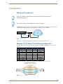
Wiring and Connections
To avoid any damage to the electronic component, installation must be performed in
an ESD safe environment.
Do not connect power to the NXB-KNX until the wiring is complete.
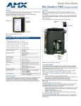
The NXB-KNX is installed between the NetLinx Master and the KNX control bus, and passes NetLinx control
commands to the KNX control bus via 2-wire twisted pair cabling, as indicated in FIG. 1:
NetLinx Master
KNX
Control
Bus
NXB-KNX
PoE injector
Ethernet 10/100
2-wire twisted pair
FIG. 1 NXB-KNX installation
After you have completed the installation, consult the Configuration section on page 5.
Ethernet 10/100 Base-T RJ-45 Wiring Configuration
The table below describes the pinouts, signals, and pairing for the Ethernet 10/100 Base-T connector and
cable.
Ethernet Pinouts and Signals
Pin
Signals
Connections
Pairing
Color
1
TX +
1 --------- 1
1 --------- 2
White-Orange
3 --------- 6
White-Green
2
TX -
2 --------- 2
3
RX +
3 --------- 3
Orange
4
no connection
4 --------- 4
Blue
5
no connection
5 --------- 5
White-Blue
6
RX -
6 --------- 6
Green
7
no connection
7 --------- 7
White-Brown
8
no connection
8 --------- 8
Brown
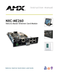
FIG. 2 diagrams the RJ-45 pinouts and signals for the Ethernet RJ-45 connector and cable.
FIG. 2 Straight-Through Wiring
NXB-KNX NetLinx KNX Interface
3
Installation
PoE (Power Over Ethernet)
The NXB-KNX uses CAT5/CAT6 wire via the Ethernet port for PoE power.
Use the PS-POE-AF Power over Ethernet Injector (FG423-80) to simplify wiring and installation by
eliminating the need for an AC outlet at each point of installation.
The NXB-KNX can be placed up to approximately 330’ (100 meters) from PoE
Injector.
If used with a non PoE-capable Ethernet switch (such as the NXA-ENET24), then an optional PSPOE-AF Power-over-Ethernet (PoE) power supply is required to provide power to the NXB-KNX.
If the NXB-KNX is used with a PoE-capable Ethernet switch (such as the NXA-ENET24PoE), then
no PoE Injectors are required.
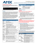
KNX Connector
The KNX connector on the rear panel is a 2-pin captive-wire connector that provides communication between
the NXB-KNX and the KNX control system via 2-wire shielded twisted pair cabling (FIG. 3).
-
KNX
Control
Bus
+
2-wire twisted pair
FIG. 3 KNX Connector wiring diagram
4
NXB-KNX NetLinx KNX Interface
Configuration
Configuration
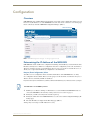
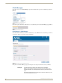
Overview
NXB-KNX units have a built-in WebConsole that allows you to make various configuration settings via a web
browser on any PC that has access to the NXB-KNX device. The web console consists of a series of web pages
that are collectively called the "NXB-KNX Configuration Manager" (FIG. 1).
Click here to log in
Hover mouse here to access
the Admin drop-down menu
FIG. 1 NXB-KNX Configuration Manager - IP Settings Page (initial view)
Determining the IP Address of the NXB-KNX
NXB-KNX units feature a built-in zero-configuration networking client that allows you to determine the unit’s
IP address via Bonjour or a similar zero-configuration client. Zero-configuration (or Zeroconf, also known as
"Bonjour") technology provides a general method to discover services on a local area network. In essence, it
allows you to set up a network without any configuration, as described below.
Bonjour (Zero-Configuration) Client
You will need a zero-configuration client to determine the IP address of the NXB-KNX. There are many
zero-configuration clients available. However, for the purposes of this document, we will refer to Bonjour for
Windows. It is free and widely available for download.
If you don’t already have it installed on your PC, download and install Bonjour for Windows before you begin.
The NXB-KNX is set to DHCP by default.
1. With Bonjour for Windows running on a PC that has access to the LAN that the NXB-KNX resides on,
connect the NXB-KNX to the network (see Wiring and Connections section on page 3).
2. In Bonjour, you will see the unit join the network at power up.
3. In Bonjour, double-click on the NXB-KNX link to access the selected unit's Configuration Manager (IP
Settings page).
4. The unit’s IP Address is displayed in the IP Settings page (FIG. 2).
At this point you can assign a new IP Address if necessary.
NXB-KNX NetLinx KNX Interface
5
Configuration
FIG. 2 Bonjour for Windows - example screen
As shown in FIG. 2, Bonjour for Windows operates as a plug-in to Internet Explorer
(version 7 shown), and is displayed in the IE Explorer Bar. If you have installed
Bonjour for Windows, but don’t see the Bonjour toolbar icon, you may need to
"unlock" and expand the toolbars to see it.
Accessing the WebConsole
From any PC that has access to the LAN that the NXB-KNX resides on:
1. Open a web browser and type the IP Address of the target NXB-KNX unit in the Address Bar.
2. Press Enter to access the WebConsole for the specified NXB-KNX unit. The initial view is the IP Settings
page (FIG. 1).
Note that this view is display-only, because you have not yet logged in. You must log in before making
changes to the IP Settings page, and to access the other pages described in this section.
Admin Menu
There are several configuration pages included in the Configuration Manager, all of which are accessed via the
Admin drop-down menu (FIG. 3):
FIG. 3 NXB-KNX Configuration Manager -Admin menu
Click on an option in this menu to access each of the configuration pages, as described in the following subsections:
6
NXB-KNX NetLinx KNX Interface
Configuration
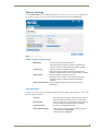
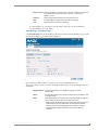
Security Settings
Select Security Settings from the Admin drop-down menu to open the Security Settings page (FIG. 4). Use
the options on the page to specify security options and login information for this NXB-KNX unit.
FIG. 4 Security Settings page
Enable / Disable Security Settings
Web Security:
Click this checkbox to enable Web Security.
When Web security is enabled, a username and password are
required to access any system Web pages (default = disabled).
Telnet Security:
Click this checkbox to enable Telnet Security.
With Telnet Security enabled, a username and password are
required to establish a Telnet or SSH connection (default = disabled).
Admin Security:
Click this checkbox to enable Admin Security.
With Admin Security enabled, a username and password are
required to modify any system configuration item (default =
disabled).
Restore Factory Defaults: Click to restore all security settings to their factory default
(all disabled).
Login Information
Use this set of options to specify a Username and Password. These will be required only if one or more of the
Security Settings are enabled.
Username:
Enter the Username that will be required to login to this unit if
security is enabled. The default Username is "administrator".
New Password:
Enter a new password that will be required to login to this unit if
security is enabled. The default Password is "password".
Confirm Password:
Re-enter the new password in this field.
Restore Factory Defaults:
Click to restore the login information to the factory defaults:
• Default Username = administrator
• Default Password = password
NXB-KNX NetLinx KNX Interface
7
Configuration
Click Accept to save your changes. Note that changes on this page take effect immediately.
Click Cancel to cancel any changes.
Logging Into the Configuration Manager (With Security Enabled)
Login is only required if the Web and/or Admin security options have been enabled on the unit.
1. Click the Login link in the upper-right corner of the initial page (FIG. 1). This invokes the Login popup
page (FIG. 5).
FIG. 5 NXB-KNX Configuration Manager - Login popup page
Enter the default login information:
Username = administrator
Password = password
2. Click the Login button.
Once you have successfully logged into the Configuration Manager, the IP Settings page is displayed, and can
be edited as needed.
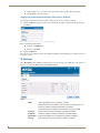
IP Settings
Select IP Settings from the Admin drop-down menu to open the IP Settings page (FIG. 6). Use the options on
the page to specify network/IP settings for this NXB-KNX unit.
FIG. 6 IP Settings page
DHCP:
Click to toggle DHCP on this unit (default = enabled).
Note that DHCP must be enabled in order for the zero-configuration client (i.e.
Bonjour for Windows) to detect the NXB-KNX on the network.
See the Bonjour (Zero-Configuration) Client section on page 5 for details.
Hostname:
8
Enter a Hostname for this unit (enabled only if DHCP is disabled).
IP Address:
Enter an IP Address for this unit (enabled only if DHCP is disabled).
Subnet Mask:
Enter a Subnet Mask for this unit (enabled only if DHCP is disabled).
Gateway:
Enter a Gateway for this unit (enabled only if DHCP is disabled).
NXB-KNX NetLinx KNX Interface
Configuration
Domain Suffix: Enter the Domain Suffix for this unit.
DNS 1, 2, 3:
Enter up to three DNS addresses for this unit.
Reboot:
Click to initiate a system reboot. IP Settings changes only take effect after a
reboot.
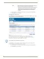
Port Settings
Select Port Settings from the Admin drop-down menu to open the Port Settings page (FIG. 7). Use the options
on the page to specify various Port settings for this NXB-KNX unit.
FIG. 7 Port Settings page
The options on this page provide inputs for enabling and disabling of HTTP, HTTPS, Telnet, SSH and FTP
ports, and allow you to change each port number from it’s standard default assignment.
HTTP Port Number:
Default = enabled, default port number = 80.
HTTPS Port Number:
Default = enabled, default port number = 443.
Telnet Port Number:
Default = enabled, default port number = 23.
SSH Port Number:
Default = enabled, default port number = 22.
FTP Port Number:
Default = enabled, default port number = 21.
Restore Factory Defaults: Click to restore all Port settings to the factory defaults.
Reboot:
NXB-KNX NetLinx KNX Interface
Click to initiate a system reboot. Port changes only take effect after a
reboot.
9
Configuration
Clock Manager
Hover the cursor over the Clock Manager option in the Admin menu to open the Clock Manager sub-menu
(FIG. 8).
FIG. 8 Clock Manager sub-menu
Each of the options listed in the submenu are also accessible via options on the Clock Manager page (FIG. 9).
FIG. 9 Clock Manager options
Clock Manager - Mode Manager
Select the main Clock Manager entry in the Admin Menu, or select Mode from the Clock Manager sub-menu,
and the Mode Manager page will be displayed (FIG. 10):
FIG. 10 Clock Manager - Mode Manager page
The options on the Mode Manager page provide inputs for selecting the current mode of the system time:
Time Synch:
Use the radio buttons to select either Network Time or StandAlone.
Note: If using StandAlone mode, the time will be valid only until the unit is
rebooted. Once the unit is rebooted, the time will be lost, and will have to be
reset.
Note that the Daylight Savings and NIST Servers tabs are enabled only if Network Time is selected as the mode.
10
NXB-KNX NetLinx KNX Interface
Configuration
Re Sync Period: Select the desired re-synch period for the clock from this drop-down menu. Resynch period options include 5 minutes, 15 minutes, 1, 2 and 4 hours
(default = 1 hour).
Timezone:
Select the appropriate Time Zone from the drop-down menu.
Date:
Use these fields to manually enter today’s date (mm/dd/yyyy).
Time:
Manually enter the current time (hh:mm:ss).
Click Accept to save your changes. Note that changes on this page take effect immediately.
Click Cancel to cancel any changes.
Clock Manager - Daylight Savings
Select Daylight Savings from the Clock Manager sub-menu (or from the main Clock Manager page), and the
Daylight Savings Manager page will be displayed (FIG. 11):
FIG. 11 Clock Manager - Daylight Savings Manager page
Note that this tab is enabled only if Network Time is selected (on the Mode Manager page).
The options on this page allow you to enable and disable daylight savings, and specify daylight savings start
and end times.
Daylight Savings: Use these radio buttons to turn daylight savings time on and off
(default = Off).
Offset:
Use these drop-down menus to specify the amount of time to offset the clock
for daylight savings.
Starts:
These options allow you to specify when to start using daylight savings time.
Select a month and time to start from the drop-down menus.
• Select Fixed to start daylight savings at a specific Day, Month and Time (an
additional field for Day is provided when this radio button is selected).
• Select Occurrence to start daylight savings at a specified occurrence
(additional fields for Week of the Month, and Day of the Week are
provided).
NXB-KNX NetLinx KNX Interface
11
Configuration
Ends:
These options allow you to specify when to stop using daylight savings time.
Select a month and time to start from the drop-down menus.
• Select Fixed to end daylight savings at a specific Day, Month and Time (an
additional field for Day is provided when this radio button is selected).
• Select Occurrence to end daylight savings at a specified occurrence
(additional fields for Week of the Month, and Day of the Week are
provided).
Click Accept to save your changes. Note that changes on this page take effect immediately.
Click Cancel to cancel any changes.
Clock Manager - NIST Servers
Select NIST Servers from the Clock Manager sub-menu (or from the main Clock Manager page), and the
NIST Server Manager page will be displayed (FIG. 12):
FIG. 12 Clock Manager - NIST Server Manager page
Note that this tab is enabled only if Network Time is selected (on the Mode Manager page).
The options on this page allow you to select the NIST server that will be queried at each clock
synchronization, and allow you to add more NIST servers to the list.
Only one NIST server is selectable at any given time.
To add a NIST server, enter the NIST Server Name, IP Address and Location in the fields provided.
To remove a NIST server from the list, click the Remove button.
Click Accept to save your changes. Note that changes on this page take effect immediately.
Click Cancel to cancel any changes.
12
NXB-KNX NetLinx KNX Interface
Configuration
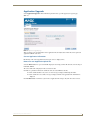
Application Upgrade
Select Application Upgrade from the Admin drop-down menu to open the Application Upgrade page
(FIG. 13).
FIG. 13 Application Upgrade page
This page allows you view information on the application file currently loaded on this unit, and to upload an
application .JAR file to the unit.
Current Application Information
Information on the current application loaded on the device is displayed here.
Browse for new Application Upload File
Select the Browse button to open a standard file display for traversing your PC's file structure, and selecting an
individual .JAR file.
The selected file name is displayed in the associated text box.
Click the Accept button to initiate the download of the selected .JAR file to the unit.
If the download fails for any reason, an error message is displayed indicating the failure.
If the download is successful, a message is displayed and the new application file information is
displayed.
Click the Reboot button to initiate a system reboot. Application file changes only take effect after a reboot.
NXB-KNX NetLinx KNX Interface
13
Configuration
Firmware Upgrade
Select Firmware Upgrade from the Admin drop-down menu to open the Firmware Upgrade Manager page
(FIG. 14). Use the options on the page to upgrade the firmware on this NXB-KNX unit.
FIG. 14 Firmware Upgrade Manager page
This page allows you view information on the firmware version currently loaded on this unit, and to upload a
firmware .JAR file to the unit.
Current Firmware Information
Information on the current firmware loaded on the device is displayed here.
Browse for new Firmware Upload File
Select the Browse button to open a standard file display for traversing your PC's file structure, and selecting an
individual .JAR file.
The selected file name is displayed in the associated text box.
Click the Accept button to initiate the download of the selected .JAR file to the unit.
If the download fails for any reason, an error message is displayed indicating the failure.
If the download is successful, a message is displayed.
Click the Reboot button to initiate a system reboot. Firmware changes only take effect after a reboot.
System information will not be updated until after a system reboot.
14
NXB-KNX NetLinx KNX Interface
Programming - Telnet Commands
Programming - Telnet Commands
Overview
The NXB-KNX supports Telnet communications. This type of terminal communication can be accessed
remotely, via TCP/IP.
Telnet is an insecure form of terminal communication, since it does not require a physical connection to the
device to connect. Further, the Telnet interface exposes information to the network (which could be intercepted
by an unauthorized network client).
It is recommended that you make initial configurations as well as subsequent
changes via the Web Console. Refer to the Configuration section on page 5.
Refer to the Terminal Commands section on page 16 for a listing of all commands available in a terminal
session.
Establishing a Terminal Connection Via Telnet
1. In your Windows taskbar, go to Start > Run to open the Run dialog.
2. Type cmd in the Open field and click OK to open an instance of the Windows command interpreter
(Cmd.exe).
3. In the CMD (command), type "telnet" followed by a space and the NXB-KNX’s IP Address info.
Example: >telnet XXX.XXX.XXX.XXX
4. Press Enter.
Unless Telnet security is enabled, a session will begin with a welcome banner:
Welcome to NetLinx vX.XX.XXX Copyright AMX Corp. 1999-2006
>
If Telnet security is enabled, type in the word login to be prompted for a Username and
Password before gaining access to the NXB-KNX.
5. Enter your username to be prompted for a password.
If the password is correct you will see the welcome banner.
If the password is incorrect, the following will be displayed:
Login: User1
Password: *****
Login not authorized. Please try again.
After a delay, another login prompt will be displayed to allow you to try again.
If after 5 prompts, the login information is not entered correctly, the following message will
be displayed and the connection closed:
Login not allowed. Goodbye!
If a connection is opened, but a valid a username / password combination is not
entered (i.e. just sitting at a login prompt), the connection will be closed after one
minute.
NXB-KNX NetLinx KNX Interface
15
Programming - Telnet Commands
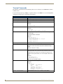
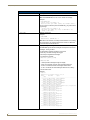
Terminal Commands
The Terminal commands listed in the following table can be sent directly to the NXB-KNX via Telnet
terminal session.
In your terminal program, type "Help" or a question mark ("?") and <Enter> to access the Help Menu,
and display the Program port commands described below:
Terminal Commands
Command
Description
----- Help -----
(Extended diag messages are OFF)
? or Help
Displays this list of commands.
DATE
Displays the current date and day of the week.
Example:
>DATE
10/31/2004 Wed
DISK FREE
Displays the total bytes of free space available.
Example:
>DISK FREE
The disk has 2441216 bytes of free space.
DNS LIST <D:P:S>
Displays the DNS configuration of a specific device including:
• Domain suffix·
• Configured DNS IP Information
Example:
>DNS LIST [0:1:0]
Domain suffix:amx.com
The following DNS IPs are configured
Entry 1-192.168.20.5
Entry 2-12.18.110.8
Entry 3-12.18.110.7
ECHO ON|OFF
Enables/Disables echo (display) of typed characters.
GET JAVA HEAP
Display the amount of memory allocated for Java pool.
This is the current Java memory heap size as measured in Megabytes.
Example: a value of 5 = 5 MB.
GET ETHERNET MODE
Displays the current ethernet configuration setting.
Settings are either "auto" in which the ethernet driver will discover it's
settings based on the network it is connected to OR <speed> and
<duplex> where speed is either 10 or 100 and duplex is either full or
half.
Example:
>GET ETHERNET MODE
Ethernet mode is auto.
Note: See SET ETHERNET MODE.
GET IP
Displays the current IP configuration.
Example:
>GET IP
IP Settings
HostName
Type
IP Address
Subnet Mask
Gateway IP
MAC Address
IPSEC ON|OFF|STATUS
16
MLK_INSTRUCTOR
DHCP
192.168.21.101
255.255.255.0
192.168.21.2
00:60:9f:90:0d:39
Enables/Disables IPSec security or displays current setting.
NXB-KNX NetLinx KNX Interface
Programming - Telnet Commands
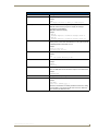
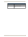
Terminal Commands (Cont.)
Command
MEM
Description
Displays the largest free block of the NXB-KNX’s memory.
Example:
>MEM
The largest free block of memory is 11442776 bytes.
MSG ON|OFF
Enables/Disables extended diagnostic messages.
• MSG On sets the terminal program to display all messages
generated by the NXB-KNX.
• MSG OFF disables the display.
Example:
> MSG ON
Extended diagnostic information messages turned on.
> MSG OFF
Extended diagnostic information messages turned off.
PING [ADDRESS]
Pings an address (IP or URL), to test network connectivity to and confirms the presence of another networked device. The syntax is just like
the PING application in Windows or Linux.
Example:
>ping 192.168.29.209
192.168.29.209 is alive.
PWD
Displays the name of the current directory.
Example:
pwd
The current directory is doc:
REBOOT
Reboots the NXB-KNX.
Example:
>REBOOT
Rebooting...
RELEASE DHCP
Releases the current DHCP lease for the NXB-KNX.
Note: The NXB-KNX must be rebooted to acquire a new DHCP lease.
Example:
>RELEASE DHCP
SECURITY SETUP
Modify system security settings.
SET DATE
Prompts you to enter the new date for the NXB-KNX.
Example:
>SET DATE
Enter Date: (mm/dd//yyyy) ->
Note: Due to the absence of a battery-backed real-time clock, setting
the current date is only valid for the life of the current run. When the
unit is rebooted, the date will be lost.
NXB-KNX NetLinx KNX Interface
17
Programming - Telnet Commands
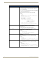
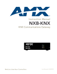
Terminal Commands (Cont.)
Command
SET DNS
Description
Sets up the DNS configuration.
This command prompts you to enter a Domain Name, DNS IP #1,
DNS IP #2, and DNS IP #3.
Then, enter Y (yes) to approve/store the information in the NXB-KNX.
Entering N (no) cancels the operation.
Note: The device must be rebooted to enable new settings.
Example:
>SET DNS
-- Enter New Values or just hit Enter to keep current
settings -Enter
Enter
Enter
Enter
Domain Suffix:
DNS Entry 1 :
DNS Entry 2 :
DNS Entry 3 :
amx.com
192.168.20.5
12.18.110.8
12.18.110.7
You have entered: Domain Name: amx.com
DNS Entry 1: 192.168.20.5
DNS Entry 2: 12.18.110.8
DNS Entry 3: 12.18.110.7
Is this correct? Type Y or N and Enter -> Y
Settings written. Device must be rebooted to enable
new settings
SET JAVA HEAP
Set the amount of memory allocated for the Java pool. This is the current Java memory heap size as measured in Megabytes.
Valid values = 2 - 8
This setting does not take effect until the next reboot.
SET ETHERNET MODE <CMD>
This command sets the current ethernet configuration settings auto OR speed = 10 | 100, duplex = full | half.
Example:
set ethernet mode auto
set ethernet mode speed=100 duplex=full
Note: See GET ETHERNET MODE.
SET FTP PORT
Enables/Disables the NXB-KNX’s IP port listened to for FTP
connections.
Note: The NXB-KNX must be rebooted to enable new settings.
Example:
>SET FTP PORT
FTP is enabled
Do you want to enable (e) or disable (d) FTP (enter e or d):
FTP enabled, reboot the NXB-KNX for the change to take affect.
SET HTTP PORT
Sets the NXB-KNX’s IP port listened to for HTTP connections.
Note: The NXB-KNX must be rebooted to enable new settings.
Example:
>SET HTTP PORT
Current HTTP port number = 80
Enter new HTTP port number (Usually 80) (0=disable HTTP):
Setting HTTP port number to
New HTTP port number set, reboot the NXB-KNX for the change
to take affect.
18
NXB-KNX NetLinx KNX Interface
Programming - Telnet Commands
Terminal Commands (Cont.)
Command
SET HTTPS PORT
Description
Sets the NXB-KNX’s IP port listened to for HTTPS connections.
Note: The NXB-KNX must be rebooted to enable new settings.
Example:
>SET HTTPS PORT
Current HTTPS port number = 443
Enter new HTTPS port number (Usually 443) (0=disable HTTPS):
Once you enter a value and press the ENTER key, you get the following message:
Setting HTTPS port number to
New HTTPS port number set, reboot the NXB-KNX for the change
to take affect.
SET IP
Sets the IP configuration.
Enter a Host Name, Type (DHCP or Fixed), IP Address, Subnet Mask,
and Gateway IP Address.
Note: For NetLinx Central Controllers, the "Host Name" can only
consist of alphanumeric characters.
• Enter Y (yes) to approve/store the information into the NXB-KNX.
• Enter N (no) to cancel the operation.
Note: The NXB-KNX must be rebooted to enable new settings.
Example:
>SET IP
--- Enter New Values or just hit Enter to keep current settings --Enter Host Name:
MLK_INSTRUCTOR
Enter IP type. Type D for DHCP or S for Static IP and then Enter:
DHCP
Enter Gateway IP:
192.168.21.2
You have entered: Host Name
MLK_INSTRUCTOR
Type
DHCP
Gateway IP 192.168.21.2
Is this correct? Type Y or N and Enter -> y
Settings written. Device must be rebooted to enable new settings.
SET LOG COUNT
Sets the number of entries allowed in the message log.
Note: The NXB-KNX must be rebooted to enable new settings.
Example:
>SET LOG COUNT
Current log count = 1000
Enter new log count (between 50-10000):
Once you enter a value and press the ENTER key, you get the following message:
Setting log count to
New log count set, reboot the NXB-KNX for the
change to take affect.
SET SSH PORT
Sets the NXB-KNX’s IP port listened to for SSH connections.
Note: The NXB-KNX must be rebooted to enable new settings.
Example:
>SET SSH PORT
Current SSH port number = 22
Enter new SSH port number (Usually 22) (0=disable SSH):
Once you enter a value and press the ENTER key, you get the following message:
Setting SSH port number to 22
New SSH port number set, reboot the NXB-KNX for
the change to take affect.
NXB-KNX NetLinx KNX Interface
19
Programming - Telnet Commands
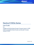
Terminal Commands (Cont.)
Command
SET TELNET PORT
Description
Sets the NXB-KNX’s IP port listened to for Telnet connections.
Note: The NXB-KNX must be rebooted to enable new settings.
Example:
>SET TELNET PORT
Current telnet port number = 23
Enter new telnet port number (Usually 23)(0=disable Telnet):
Once you enter a value and press the ENTER key, you get the following message:
Setting telnet port number to 23
New telnet port number set, reboot the NXB-KNX for the
change to take affect.
SET TIME
Sets the current time.
Example:
>SET TIME
Enter Date: (hh:mm:ss) ->
Note: Due to the absence of a battery-backed real-time clock, setting
the current time is only valid for the life of the current run. When the
unit is rebooted, the time will be lost.
SHOW LOG
Displays the log of messages stored in the NXB-KNX's memory.
The NXB-KNX logs all internal messages and keeps the most recent
messages. The log contains:·
•
•
•
•
Entries starting with first specified or most recent
Date, Day, and Time message was logged
Which object originated the message
The text of the message:
SHOW LOG [start] [end]
SHOW LOG ALL
- <start> specifies message to begin the display.
- If start is not entered, the most recent message will be first.
- If end is not entered, the last 20 messages will be shown.
- If <ALL> is entered, all stored messages will be shown, starting
with the most recent.
Example:
>SHOW LOG
Message Log for System 50 Version: v2.10.75
Entry
Date/Time
Object
Text
----------------------------------------------------------------1: 11-01-2001 THU 14:14:49 ConnectionManager
Memory Available = 11436804 <26572>
2: 11-01-2001 THU 14:12:14 ConnectionManager
Memory Available = 11463376 <65544>
3: 11-01-2001 THU 14:10:21 ConnectionManager
Memory Available = 11528920 <11512>
4: 11-01-2001 THU 14:10:21 TelnetSvr
Accepted Telnet connection:socket=14 addr=192.168.16.110 port=2979
5: 11-01-2001 THU 14:05:51 Interpreter
CIpEvent::OnLine 10002:1:50
6: 11-01-2001 THU 14:05:51 Interpreter
CIpEvent::OnLine 128:1:50
7: 11-01-2001 THU 14:05:51 Interpreter
CIpEvent::OffLine 128:1:50
8: 11-01-2001 THU 14:05:51 Interpreter
CIpEvent::OnLine 96:1:50
9: 11-01-2001 THU 14:05:51 Interpreter
CIpEvent::OffLine 96:1:50
10: 11-01-2001 THU 14:05:51 Interpreter
CIpEvent::OnLine 128:1:50
11: 11-01-2001 THU 14:05:51 Interpreter
CIpEvent::OnLine 96:1:50
12: 11-01-2001 THU 14:05:51 Interpreter
CIpEvent::OnLine 5001:16:50
13: 11-01-2001 THU 14:05:51 Interpreter
CIpEvent::OnLine 5001:15:50
14: 11-01-2001 THU 14:05:51 Interpreter
20
NXB-KNX NetLinx KNX Interface
Programming - Telnet Commands
Terminal Commands (Cont.)
Command
Description
SHOW HEAP
Displays heap usage statistics.
SHOW MEM
Displays the memory usage for all memory types.
TIME
Displays the current time on the NXB-KNX.
Example:
>TIME
13:42:04
NXB-KNX NetLinx KNX Interface
21
Programming - Telnet Commands
22
NXB-KNX NetLinx KNX Interface
Programming - Telnet Commands
NXB-KNX NetLinx KNX Interface
23
AMX. All rights reserved. AMX and the AMX logo are registered trademarks of AMX. AMX reserves the right to alter specifications without notice at any time.
©2008
5/08
It’s Your World - Take Control™
3000 RESEARCH DRIVE, RICHARDSON, TX 75082 USA • 800.222.0193 • 469.624.8000 • 469-624-7153 fax • 800.932.6993 technical support • www.amx.com