1
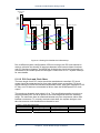
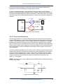
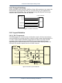
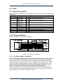
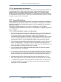
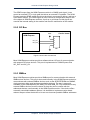
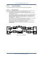
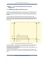
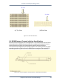
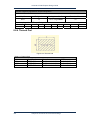
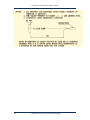
Advantech SOM-Express Design Guide
5.4.3.2 RGB Output Current Balance Path
Analog R, G and B (red, green and blue) traces should be designed to be as short as
possible. Careful design, however, will allow considerable trace lengths with no
visible artifacts. GNDRGB is an "analog current balance path" for the RGB lines. In
terms of layout, GNDRGB should follow 2 traces that encapsulate the RGB traces all
the way to the D-shell connector (VGA Port) and should not be tied to ground until
connected to the Right Angle D-type connector.
15~30 mils wide
VGA Connector
SOM-Express
12 mils wide
VGA_R
VGA_G
VGA_B
RGBGND
RLC
D-Sub 15
RGBGND
"? " :ground via on RGBGND balance path
Figure 5-21 RGB Output Layout Guidelines
58
Chapter 5 Carrier Board Design Guidelines