1
Contractor SECTION
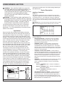
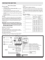
Control Panel to supply the correct voltage and control signals by
the manufacturer. The installer must connect the control lines for
the VFMQ storage heaters and the outdoor temperature sensor.
The outdoor temperature sensor is a low voltage device connected
to terminals W1 and W2. Properly sized 2-conductor wire should
be strain relieved and connected to the W1, and W2 terminals.
Care should be taken to separate the low voltage wiring from the
high voltage wiring as dictated by the relevant electrical code.
The storage heater control lines are 208/240VAC control lines that
must be run separately to the supply lines to the VFMQ storage
heaters. Properly sized 2-conductor wire should be strain relieved
and connected to the terminals marked Z1 and Z2 to control the
charging of the VFMQ storage heaters.
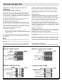
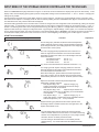
The connections at terminals L and N should not be interchanged
The LL (runtime), LF (charge release), LZ (additional charging)
and KU (heating curve switching) pilot wires must be connected in
phase with L (charging)
Should a phase be connected to terminal W1, W2, Z1 or Z2 due to
a mistake in the wiring, the unit will be destroyed.
Calculating the Control Output
•
•
•
The maximum control output of the Storage Heater Controller
charge control is 300 W.
The control output of the heating system depends on the device
type and number of devices. It can be calculated by adding the
control outputs of all storage heaters.
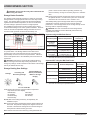
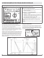
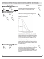
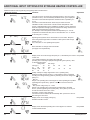
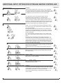
LF: Activated when LF (charge release) terminal is activated
LZ: Activated when LZ (runtime) terminal is activated
KU: Activated when KU (heating curve switching) terminal is
activated
ED: Activated when the control signal is output
ATM: Activated in external temperature averaging operation
(ATM (external temperature averaging) = Ja)
Abw: Activated in period of absence (Abw) mode
SUT:Activated when the control signal is suppressed
in the daytime characteristic curve
D: Activated in direct activation mode
SUS: Activated when the control signal is suppressed and the
effective external temperature (ATW) is higher than the value
set for E2
: Weekly programme display “WeP=Ja”
:“LSU (charge synchronisation with timer) = Ja
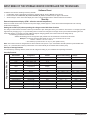
LED operating mode display:
If display is:
Not lit – operator mode is active
Green light – technician menu display mode is active
Red light – technician menu setting mode is active
Orange light (brief) – software has been reset
Figure 10
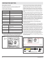
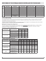
The following table shows the control outputs of selected storage heater types. Device type Control output per device
VFMQ 10 Watts
Storage Heater Controller Set-Up
Explanation of multi-function display items
LL: Activated when LL terminal is activated
Figure 9
10
www.dimplex.com