1
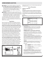
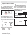
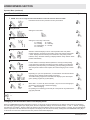
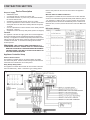
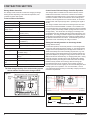
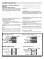
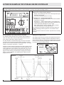
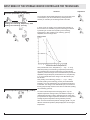
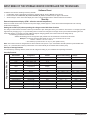
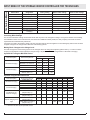
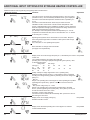
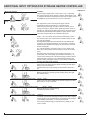
Contractor SECTION
Scope of supply
•
•
•
•
•
•
•
Device Description
208/240VAC, 60Hz
4 x terminals rated to a maximum of 240V, 30A
24V terminal and return, to power a dry contact that indicates
the current electrical rate.
A dipswitch to select/invert the logic of the dry contact.
A set of 3 dipswitches to set the number of hours from the start
of the peak rate to the start of the midday reduced rate period,
1-8 hours.
A set of 3 dipswitches to set the duration of the midday reduced
rate period, 1-8 hours.
A dipswitch to select the relay delay mode (random or stepped).
that the user prefers for the 4 circuits connected to the appliance
controller.
Mid-Peak Offset and Mid-Peak Duration
The Appliance Controller will use its internal timer to allow selected
circuits to be activated during the Mid-Peak period defined by switch
1-6. Switches 1-3 define the time, in hours, between the end of the
Off-Peak period and the start of the Mid-Peak period. Switches 4-6
define the time, in hours, between the start and end of the Mid-Peak
period.
DIP Switch Settings
Function
The appliance controller will supply power the connected appliance
during the Off-Peak periods and Mid-Peak periods (if selected by
the user). The appliance controller will provide power based on the
settings input with the DIP switch selectors located on the appliance
controller circuit board. To access these settings the enclosure
must be opened.
Warning: THIS CONTROL PANEL CONTAINS UP TO 5
SEPARATE CIRCUITS. ENSURE THAT ALL CIRCUITS HAVE
BEEN DE-ACTIVATED AT THE SOURCE BEFORE OPENING
THE ENCLOSURE. FAILURE TO DO SO COULD RESULT IN
ELECTRIC SHOCK OR DEATH
Appliance Controller Setup
External Switch Indicator
The Appliance controller relies on an external switch to indicate
the current rate period. Switch 8 selects the logic that the external
switch will use to indicate the current rate period.
Relay Startup Delay Pattern
The Appliance Controller will not allow all of the circuits to become
active simultaneously. Switch 7 selects the type of delay pattern
Figure 4
7