1
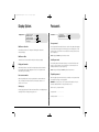
7211 Digital English Cover 10/4/02 5:16 pm Page 2
Setup Guide
Guide d'installation
Setup-Anleitung
Guía de programación
Guida per
l'impostazione
www.dedicatedmicros.com
7211 Digital English Cover 10/4/02 5:16 pm Page 3
Warning: Do not move the unit whilst the power is connected.
Important note: Do not place heavy items on the Digital Sprite 2.
7211 Digital English Cover 10/4/02 5:16 pm Page 4
7211 DigitalManual Update
10/4/02
5:12 pm
Page 1
Contents
•
•
•
•
•
Introduction
Important Safeguards
Installing Digital Sprite 2
Quick Install
Connecting External Devices
- Connecting Telemetry Cameras
- Connecting Storage Devices
- Connecting to an Ethernet Network
- Connecting 485-bus Devices
- Connecting Audio Devices
- Recording Audio
• Configuring Digital Sprite 2
- Using the Menus
- Time, Date & Language
- Camera Viewing
- Schedule
- Camera Recording
- Record Schedule
- Alarm Setup
- Activity Setup
- Display Options
- Passwords
- System Options
- Camera Setup
- Alarm and Presets
- Activity Camera Setup
• Appendix 1 - Configuring for tape archive
• Notes
Introduction
1
3
4
5
6
6
7
9
10
12
12
13
13
14
15
16
16
17
19
20
21
21
22
24
25
26
27
30
What is Digital Sprite 2?
Digital Sprite 2 is a cost effective and easy to use video multiplexer, digital video
recorder, single channel audio recorder, and network video transmitter in a one
box solution.
A video multiplexer?
•
•
•
•
Designed with security in mind
Easy to use
Operates like a traditional multiplexer, not a PC
All the feature you would expect from a Dedicated Micros multiplexer:
- Main and Spot monitor
- Multiscreen displays
- Activity detection
- Alarm handling
- Schedules for day, night, and weekend
- User defined record rates
- 485-bus networking
A digital video recorder?
• Playback and record simultaneously, without affecting recording
• 31 days or more of 24 hour time-lapse recordings in one box*.
• Instant access to images recorded on the hard disk with no tapes.
Single channel audio recorder?
• Record a single channel of audio stream along with the images.
Network transmission?
• View live and playback images across the network.
• No extra software to buy, Network Viewing software for Windows™ provided.
• Copy images across the network
*Refers to the 320GB model
1
7211 DigitalManual Update
10/4/02
5:12 pm
Page 2
Features:
Installation
Auto detect cameras on power up
Auto detect external storage on power up
Default 24-hour recording at S-VHS quality
Loop-through connections
Audio
✔
✔
✔
✔
Operation
Play, record, copy and transmit simultaneously
Hidden camera option
Control via IR remote control
✔
✔
✔
Playback
VCR style playback
Full, Quad, and PIP playback
✔
✔
Events
Activity detection
Alarms
Event log with preview window
Autocopy events to Zip® and Jaz®*
Pre and Post event times
✔
✔
✔
✔
✔
Telemetry
Coaxial – BBV, Dennard, Pelco
Serial – Ultrak, Ademco/VCL, JVC, Dennard, Panasonic,
Aritech/Kalatel, Sensormatic, Pelco-P
DTMF/485-bus – Dedicated Micros
Telemetry presets on alarm
Record audio in real time
✔
Remote keyboard control (optional)
Remote keyboard compatible
Control of multiple units
Telemetry controller
✔
✔
✔
Network viewing
Live viewing
Playback viewing
Up to 5 network users at once
Telemetry control
Copy images across networks
E-mail on event activation
✔
✔
✔
✔
✔
✔
External storage devices
Zip® and Jaz®*
RAID
Hewlett Packard DDS
Yamaha/Plextor CDR (check for compatible models)
✔
✔
✔
✔
The manual has two parts:
✔
✔
✔
✔
1. An operators card
– giving details of installation and operation.
2. A Setup guide (this document)
– giving details of configuring the Digital Sprite 2 and external devices.
*Check for compatible models and availability for models.
2
7211 DigitalManual Update
10/4/02
5:12 pm
Page 3
Important Safeguards
Read Instructions
All the safety and operating instructions should be read before the unit
is operated.
Power Sources
This unit should be operated only from the type of power source
indicated on the manufacturer’s label.
Servicing
Do not attempt to service this unit yourself as opening or removing
covers may expose you to dangerous voltage or other hazards.
Refer all servicing to qualified service personnel.
Ventilation
Ensure unit is properly ventilated to protect from overheating.
WARNING
To prevent fire or shock hazard, do not expose this equipment to rain or
moisture. The lightning flash with arrowhead symbol within an equilateral
triangle is intended to alert the user of this equipment that there are dangerous
voltages within the enclosure which may be of sufficient magnitude to constitute
a risk of electric shock.
REGULATORY NOTES FCC AND DOC INFORMATION
(USA and Canadian Models Only)
WARNING: This equipment has been tested and found to comply with the limits
for a Class A digital device, pursuant to part 15 of the FCC rules. These limits are
designed to provide reasonable protection against harmful interference when the
equipment is operated in a commercial environment. This equipment generates,
uses, and can radiate radio frequency energy and, if not installed and used in
accordance with the instruction manual, may cause harmful interference to radio
communications. Operation of this equipment in a residential area is likely to
cause harmful interference in which case the user will be required to correct the
interference at their own expense.
If necessary, the user should consult the dealer or an experienced radio/television
technician for corrective action. The user may find the following booklet prepared
by the Federal Communications Commission helpful: “How to Identify and
Resolve Radio-TV Interference Problems”.
This booklet is available from the US Government Printing Office, Washington,
DC20402, Stock No. 004-000-00345-4.
This reminder is provided to call the CATV system installer’s attention to Art.
820-40 of the NEC that provides guidelines for proper grounding and, in
particular, specifies that the cable ground shall be connected to the grounding
system of the building, as close to the point of cable entry as practical.
CE Mark
This product is marked with the CE symbol and indicates compliance
with all applicable directives.
Directive 89/336/EEC.
A “Declaration of Conformity” is held at Dedicated Micros Ltd.,
11 Oak Street, Swinton, Manchester M27 4FL.
3
7211 DigitalManual Update
10/4/02
5:12 pm
Page 4
Installing
Before you start:
A quick overview of digital recording
Check the contents of the box:
Digital multiplex recorders work in exactly the same way as analogue multiplexers
except that they use hard disks and digital tape to store video, instead of VCR tapes.
❑
❑
❑
❑
❑
❑
❑
Digital Sprite 2
IR remote handset
PSU
Mains cable with three pin plug fitted (North America)
Mains cable without plug fitted (other regions)
Rack mount kit (rack mount ears, rear supports, and fixing screws)
485-bus cable
Choosing a location for installation
Digital Sprite 2 is designed to be rack or desk mounted. The following precautions
must be taken when installing Digital Sprite 2:
• Openings in the unit’s case are provided for ventilation. To prevent
overheating, these openings should not be blocked or covered.
• When stacking units, ensure there is at least a 1/2" (1.5 cm) gap between
each unit.
• Ensure there is a 1" (3cm) gap on either side of the unit.
• Ensure the unit is not located in an area where it is likely to be subjected to
mechanical shocks.
• The unit should be located in an area with low humidity and a minimum of
dust. Avoid places like damp basements or dusty hallways.
• If using external storage, refer to the manufacturer’s instructions for
placement details.
Analogue recording uses time-lapse recording to extend the length of time
recorded onto a 3-hour tape - recording fewer pictures every second.
Adjusting the number of pictures recorded every second also extends the length
of time recorded onto the hard disk of a Digital Sprite 2. However, other factors
also determine the amount of time that can be stored on the disk of a digital
multiplex recorder:
• The image quality
• The record rate
• The hard disk capacity
Image quality
Digital multiplex recorders store images in a compressed format, allowing images
to be recorded more efficiently. The higher the compression, the smaller the file
size, but the image quality will suffer. Digital Sprite 2 can compress images
between 6KB and 45KB.
Kilobytes and gigabytes are units of storage:
1GB = 1024 Megabytes (MB)
1MB = 1024 Kilobytes (KB)
With analogue recording, the image quality is dependent on the type of VCR
being used; VHS or S-VHS. Digital Sprite 2 allows the image quality to be altered
by adjusting the image size, for example, VHS quality is 14KB, S-VHS is 18KB, and
greater than S-VHS is 25KB*.
Using a larger image size will fill the hard disk faster than a smaller image size, as
more space is required to store it. To achieve the same amount of recording time
when a larger image size is used requires the record rate (PPS) to be reduced.
* Note that as for all digital recording, image quality can vary for different scene types, S-VHS
quality may be 18KB in one scene, but it may be 30KB or more to get the same quality in a
scene with more detail.
4
7211 DigitalManual Update
10/4/02
5:12 pm
Page 5
Quick install
Record rate
The record rate is the amount of pictures recorded to disk in a second, or pictures
per second (PPS). This is a system wide figure, so whether 1 or 16 cameras are
recorded, the record rate remains the same. The update rate per camera can be
worked out using the record rate:
Update rate
=
Digital Sprite 2 can be installed in as little as 4 steps, and being plug-and-play,
cameras will be detected and recorded automatically.
No. of cameras
Record rate
A table of common record rates can be found in Appendix 2.
Hard disk capacity
STEP 1. Connect cameras
Analogue VCRs use 3-hour tapes which record a finite number of images. Unlike a
VCR, the number of images that can be recorded to a digital multiplex recorder can
be increased by using a larger capacity hard disk. Digital Sprite 2 has a range of hard
disk sizes, at the time of writing 80, 160, and 320GB disk sizes are available.
Using a larger hard disk will allow image quality, recording rate, or recording time
to be increased. For example, an 80GB disk can record for 8 days at the default
settings (24-hour time-lapse mode at S-VHS quality).
Tip: As a rule-of-thumb recording at the default settings* will use 10GB of
storage per day, i.e. an 80GB unit will record for 8 days.
Calculating recording time
Digital Sprite 2 calculates the recording time automatically when the record rate
and image quality are entered. Alternatively, an interactive record calculator is
available for download from our web site:
www.dedicatedmicros.com
* 24-hour time-lapse mode, 6PPS, and S-VHS quality images, 18KB
Connect cameras to the video inputs marked VID1 to VID9 (9-way unit) or VID16
(16-way unit). Use the bottom row of connectors for looping through to other equipment.
STEP 2. Connect monitors
Connect the video output marked MON A to the Main monitor (digital playback
and multiscreens).
Connect the video output marked MON B to the optional Spot monitor (analogue
full-screen images).
STEP 3. Connect the external devices
If external devices need to be connected to Digital Sprite 2, go to the next section
– ‘Connecting external devices’, before proceeding to Step 4.
STEP 4. Connect power
Once the Digital Sprite 2 is in its final position and all external devices have been
fitted and powered, connect the PSU to the rear of the unit and apply the power.
The power-up procedure may take up to one minute before Digital Sprite 2 can
be used.
will now record all cameras in a 24-hour time-lapse mode
without any further programming!
5
7211 DigitalManual Update
10/4/02
5:12 pm
Page 6
Connecting external devices
Digital Sprite 2 uses 485-Bus networking to interconnect Dedicated Micros
products and accessories. Storage devices can be connected to the SCSI port, and
telemetry cameras can be connected to the serial port. Devices that can be
connected to Digital Sprite 2 include:
Telemetry cameras
Storage devices
Ethernet networks
485-Bus devices
Audio devices
Serial telemetry
Digital Sprite 2 currently supports a number of domes using serial telemetry. Serial
telemetry requires a twisted-pair connection from the Digital Sprite 2’s serial port to
the dome. Serial telemetry can be star configured – from the Digital Sprite 2 serial
port to each receiver, or delta configured – each receiver daisy chained together, or
a combination of the two. Each receiver needs to be addressed according to its
camera number – consult your receiver documentation for details.
Serial port connection
The serial port on Digital Sprite 2 is a 9-way male D-type connection. A 9-way Dtype female plug is required with the following pin-outs:
Connecting telemetry cameras
Digital Sprite 2 has in-built coaxial, serial (RS-232/485), and 485-Bus telemetry,
and DTMF telemetry using an optional telemetry adaptor. A remote keyboard is
used to control telemetry from the Digital Sprite 2.
The brand of telemetry must be set in the ‘Alarms and Presets’ menu.
Coaxial telemetry
Digital Sprite 2 currently supports Pelco Coaxitron* and BBV, using a BBV RX-100
protocol converter allows control of most major manufacturer’s domes.
*The Tour, Patrol, and Auto-pan features are not available when using Pelco coaxitron domes on a
Digital Sprite 2. If you require these features you must use either a BBV RX-100 protocol converter
or serial telemetry.
Viewed from the solder side.
PIN
RS-232
RS-485
1
2
3
4
5
6
7
8
9
nc
RX
TX
GND
GND
nc
RTS
CTS
nc
Data A
nc
nc
GND
GND
nc
nc
nc
Data B
nc = no connection
Note: The serial port must be configured for serial telemetry in the System
Options menu.
6
7211 DigitalManual Update
10/4/02
5:12 pm
Page 7
485-Bus/DTMF telemetry
2. External CD Writer.
Dedicated Micros telemetry receivers can be controlled using 485-Bus or DTMF
(telephone tones). When using 485-Bus telemetry the receiver is connected
directly to the 485-Bus connectors on the back of the unit. When using DTMF
telemetry a telemetry adaptor (TAD3) is required to convert the telemetry
commands into DTMF tones. DTMF and 485-Bus telemetry can be configured in a
star or delta configuration.
Images can be copied from the internal hard disk onto an external SCSI CD writer.
All images are digitally signed for authentication purposes before being
transferred to CD. The contents of the entire CD are also digitally signed. A small
CD playback program is also recorded to allow these images to be played back on
a third party PC without having to install any extra software.
Connecting storage devices
Yamaha CRW 2200 SX – VK
Images are recorded to the internal hard disk for instant playback and searching
by the operator. The capacity of the internal disk affects the amount of images
and time that can be recorded. For example, a 80GB Digital Sprite 2 can record
for 8 days at default record rates, but a 320GB Digital Sprite 2 can record for 31
days at the same record rates.
The internal hard disk is a temporary storage device as the images are constantly
being overwritten after a certain period of time. If images need to be kept for
longer then external storage is required. The 50-way high density SCSI-2 port on
the rear of the Digital Sprite 2 is used to connect to external storage devices.
There are three types of external storage devices which can be used:
Compatible CD writers at the time of writing include:
Yamaha CRW 3200 SX – VK
Plextor Plexwriter PX-W1210-TSE
The table below shows the record time on CD for typical record rates.
CD-R 640MB
1PPS
2PPS
3PPS
6PPS
12PPS
25PPS
9h 46m
4h 49m
3h 12m
1h 36m
48m
23m
Note: You may need to purchase a SCSI cable to attach the CD writer to the Digital
Sprite 2. The connection on the Digital Sprite 2 is a 50-pin HD SCSI-2.
1. RAID – Redundant Array of Independent Disks
RAID units contain hard disks which adds to the internal storage, effectively
extending the amount of images which can be recorded before being overwritten.
RAID units give protection if a fault occurs. If a disk fails in a RAID the images will
continue to record to another disk in the array. RAID also allows faulty disks to be
hot-swapped – replaced whilst the RAID is powered.
7
7211 DigitalManual Update
10/4/02
5:12 pm
Page 8
3. Iomega Zip® and Jaz® disks*
4. External tape storage
Images can be copied from the internal hard disk or RAID onto removable Zip® or
Jaz® disks for longer-term storage. All images are digitally signed before being
transferred to disk. These images can be played back on a Windows™ PC with a Zip
or Jaz drive connected and DM Playback software installed.
Images recorded to the internal disk can be automatically archived to Hewlett
Packard DDS. This allows a ‘tape-a-day’ recording solution, similar to that of a
multiplexer and VCR. The disk size does not have to be large when using tapes
to archive images, although the disk size determines what is instantly accessible
from the Digital Sprite 2.
Note: PC playback is available to download from our web site, the unit itself, and
is included with the unit on Disk.
Zip® and Jaz® disks are available in different disk capacities, the table below shows
the recording times at typical recording rates (at S-VHS image quality, 18KB):
1PPS
2PPS
3PPS
6PPS
12PPS
Iomega Zip® 100MB
1h 30m
45m
30m
15m
7m
25PPS
3m
Iomega Zip® 250MB
3h 46m
1hr 53m
1h 15m
37m
18m
9m
Iomega Jaz® 1GB
15h 4m
7h 32m
5h 1m
2h 30m
1h 15m
36m
Iomega Jaz® 2GB
30h 8m
15h 4m
10h 2m
5h 1m
2h 30m
1h 12m
To play back images recorded to tape you will need to use a second tape unit
connected to a Windows™ PC. PC playback* software is required to play back
the images on the PC.
Note: Due to the mechanical wear of tape drives and tapes we have found that they
are not generally as reliable as using disk and RAID storage alone, therefore we
would not recommend using tape storage unless there is no other option available.
The table below shows the number of hours a tape will last for when used at
different record rates (at S-VHS images quality, 18KB)
6hr
Times indicate all cameras being copied to the disk.
* Iomega SCSI Zip® and Jaz® disk drives may not be available in all countries,
check with your PC peripheral supplier first.
12hr
48hr
72hr
168hr
HP DDS-3 12GB
25PPS
14PPS
7PPS
3PPS
2PPS
1PPS
HP DDS-4 20GB
25PPS
23PPS
11PPS
5PPS
3PPS
1PPS
See Appendix 1 for details of configuring Digital Sprite 2 for tape archiving.
* PC playback software is provided with the unit
8
24hr
7211 DigitalManual Update
10/4/02
5:12 pm
Page 9
Connecting multiple external devices
Connecting to an Ethernet network
Up to seven storage devices can be daisy chained from the SCSI port on the rear
of the Digital Sprite 2. Each device must have a unique address and the last
device on the chain must be terminated, check with the device documentation
for details of addressing and termination.
Digital Sprite can be connected to a standard 10-baseT Ethernet network allowing
full control of the Digital Sprite 2 from a remote location.
Network connection
Note: Only one tape drive can be connected to the SCSI bus.
To connect a Digital Sprite 2 to a network you will need the following items:
• A RJ-45 network cable (CAT5 or equivalent).
The table below gives capacity and typical uses of each storage device.
• A static IP address and Subnet mask (some networks may also require a
Default gateway, consult the network administrator for advice).
External storage
Capacity
Description
Typical use
RAID
Currently up to
375GB*
Disk array with
fault tolerance
Longer term storage
with instant access
CD-R
640MB
Removable media
Clip storage
Iomega Zip®
100 or 250MB
Removable media
Event or clip storage
2. Tap the menu button until the ‘System Options’ page is displayed.
Iomega Jaz®
1 or 2GB
Removable media
Event or clip storage
3. Use the cursors to select ‘Network settings’
Hewlett Packard
DDS-3
12GB
Digital storage tape
Long term
tape-a-day archive
Hewlett Packard
DDS-4
20GB
Digital storage tape
Long term
tape-a-day archive
* Single RAID capacity, up to 7 RAIDs can be connected to Digital Sprite 2.
To configure the Digital Sprite 2 on the network you will need to perform the
following steps:
1. Enter the Digital Sprite 2 menu (press and hold the menu button).
4. Enter the ‘Network settings’ menu by highlighting ‘Edit’ and pressing the up or
down cursor.
5. Enter the IP address, Subnet mask and Default gateway in the spaces.
Note: The addresses are four sets of three digits, if you have only two digits
in the address insert a 0 before the number i.e. 123.123.123.001
6. Press the menu button to exit the menu.
7. Press camera 1 to accept the changes and reboot the system, or press menu
again to exit without changing the settings.
9
7211 DigitalManual Update
10/4/02
5:12 pm
Page 10
Viewing images across the network
Viewing images across the network using a web browser
Digital Sprite 2 can use either a web browser or Network Viewing Software to
view images across the network. The Network Viewing Software can be
downloaded from the unit onto your local PC using the network connection.
It is possible to use Microsoft Internet Explorer (version 5.X and above) and
Netscape Navigator (version 4.7X) to view images from a Digital Sprite 2. Follow
the previous instructions to display the Digital Sprite 2 web page, but click on the
‘Web viewer’ icon instead of the ‘PC viewer application’ icon. It will be necessary
to enter a username and password at this point, the default username and
password is user and password.
To download the network viewing software:
1. Open your web browser software on your PC.
2. Enter the IP address of the Digital Sprite 2 in the ‘Address’ box in Internet
Explorer or Netscape and press Enter. Remove all preceding 0’s, i.e.
123.123.123.001 in the Digital Sprite 2 should be entered as 123.123.123.1 in
the web browser.
3. A web page from the Digital Sprite 2 is loaded. Click on the ‘PC viewer
application’ icon, you will be prompted to Save or Run the program.
Note: The web viewer does not have all the features of the Network Viewing
Software, but it is useful if it is not possible to download the software, or if you
want to view the images from an offsite location i.e. via the web.
Viewing images across the network using an Apple Mac or Linux
There is limited support for viewing images using an Apple Mac or Linux based
operating system using Netscape Navigator 4.7X web browser.
4. Select ‘Run this application from its current location’
5. The software will download and install, follow onscreen prompts.
6. The program can be found in Start>Programs>DM Network Viewer.
Details of using the Network Viewing Software can be found in the ‘User Guide’
in the Network Viewing Software folder.
The minimum specification PC for viewing images over a network is:
Connecting 485-bus devices
Digital Sprite 2 uses the 485-bus networking system to allow multiple Digital
Sprites, remote keyboards, alarm modules, video switchers, and other accessories
to be connected together. The total length of the 485-bus network can be up to
1500m (4900ft).
Connecting alarms
• 200Mhz CPU
• 64MB RAM
• 4MB video card (capable of 16 million colours)
• Minimum of 800x600 screen resolution
10
An optional alarm module (DM/CI01) is required if alarms are to be added to
Digital Sprite 2. The advantage of using alarm modules is that the alarm
connectors do not have to be routed back to the Digital Sprite 2. Multiple alarm
modules can be used on the 485-bus with alarms connected to each module.
7211 DigitalManual Update
10/4/02
5:12 pm
Page 11
To add alarms:
An example of connecting a remote alarm box to the Digital Sprite 2:
• Connect the corresponding alarm contact to the alarm input, i.e. Alarm2
would be connected between ground (GND) and A2.
• If multiple alarm modules are required then each will need to be addressed;
consult the alarm module documentation for details.
• Connect the 485-bus cable from the alarm box to one of the 485-bus sockets
on the Digital Sprite 2.
• The polarity of the alarms (normally open/closed) is set in the ‘Alarms and
Presets’ menu page.
Remote keyboards
A remote keyboard (DM/KBS3) can be connected to the Digital Sprite 2 to provide
extra functionality:
Note: The alarm contacts do not have to correspond to the camera number, for
example alarm 2 could trigger camera 1, 2 and 3 into alarm mode, see page 19
and 25 for details of setting up alarms.
• Remote control from a distance of up to 1500m (4900ft).
An alarm trigger can be programmed to perform any of the following:
• Control of multiple Digital Sprites.
• Control of on-board telemetry.
Action
Menu page
Close/Open relay 1
Alarm Setup
Automatically copy the alarm camera to Zip® or Jaz®
Alarm Setup
Display the alarm camera on screen
Alarm Setup
Change the record rate
Record Schedule
Record exclusively or interleave the alarm cameras
Record Schedule
Sequence the alarms on the spot monitor
Default Setting
• Jog/shuttle playback using the joystick.
• Panic alarm button (record all cameras at the alarm rate and activate the
alarm relay, R1)
11
7211 DigitalManual Update
10/4/02
5:12 pm
Page 12
The example below shows a remote keyboard connected of the Digital Sprite 2:
Connecting Audio devices
Digital Sprite 2 can record and playback a single stream of audio linked to camera 1.
There are two audio input ports: MIC IN and LINE IN, and an audio output: LINE OUT.
Connecting a microphone to MIC IN.
Connect the microphone into the 3.5mm jack plug labelled MIC IN. It is important
to select the correct type of microphone for connection to the Digital Sprite 2.
Digital Sprite 2 requires an electret microphone with a sensitivity of –50dBV or
better.
Video switchers
Video switchers allow multiple Digital Sprites to be controlled from a single or pair
of monitors. This allows the flexibility of controlling up to 256 cameras from a
single location without having to purchase extra matrix equipment. The video
switcher routes the monitors from the Digital Sprite 2 being controlled to the
operator’s monitors, up to 16 control positions can have monitor switching.
The example below shows two Digital Sprites controlled from individual control
points. The video switcher routes the monitor outputs from the Digital Sprites to
the control points:
Connecting a pre-amplifier to LINE IN.
Where additional microphone gain and/or adjustable gain is required, an external
microphone pre-amplifier with adjustable gain is recommended. A microphone
pre-amplifier will provide a line level 1V pk-pk signal that can be connected to the
RCA socket labelled LINE IN on the Digital Sprite 2.
The line level input has the following specification:
Line IN
47kΩ input impedance, 1V pk-pk
Connecting the LINE OUT to an amplifier.
Connect the RCA socket labelled LINE OUT to an external amplifier or powered
loudspeakers.
The line level output has the following specification.
Line OUT
1V pk-pk
Recording audio
Once the microphone or pre-amplifier is connected to the Digital Sprite 2, the
option to record audio should be enabled in the menu. See page 23 for details
of enabling audio recording.
Tip: Each 485-bus device is supplied with a 2m 485-bus cable. To extend the distance
between devices, two 485-bus junction boxes and 12v-power supply are required.
A total distance for the whole 485-bus network can be up to 1500m (4900ft).
12
It is advised that you test the quality of audio playback, it may be necessary to
increase the gain of the microphone.
As the audio is linked to camera 1, it is required that camera 1 be viewed, either
in a full screen or in a quad view during playback to hear the audio.
7211 DigitalManual Update
10/4/02
5:12 pm
Page 13
Configuring
Using the menu
To view the next page
Digital Sprite 2 uses a paged menu system to guide the installer through the
installation process.
Tap the menu key to view the next page.
Entering the menu
Tip: Tapping the 7or8 keys will allow you to go back or forward a page in
the menus.
There are two types of menus, User and Installer. The user menu will display only
the ‘Time, Date, and Language’ and ‘Schedule’ pages. The installer menu can
display all the menus.
To exit the menu
To enter the Installer menu:
Press and hold the menu key.
Tip: Cycling though all the menus by tapping the menu key will also exit
the menus.
To enter the User menu:
Tap the menu key.
Example of using the menu to change the time:
Press and hold the menu key to exit the menus.
Time, Date & Language
Navigating the menu
The menus are displayed with ‘options’ on the left-hand column and ‘settings’ in
the right hand column. A cursor (highlighted text) can be moved using the
cursor keys on the front panel, or the joystick on the remote keyboard.
Date
Time
Date format
Language
DST
System Shutdown
W
31/04/2002
12:00
Day, Month
English
Auto
Disabled
Time, Date & Language
Cursor
Date
Time
Date format
Language
DST
System Shutdown
Options
W
31/04/2002
12:00
Day, Month
English
Auto
Disabled
Settings
1. Press and hold the menu key to enter the installer menu. The ‘Time, Date &
Language’ page is displayed.
Time, Date & Language
Date
Time
Time
Date format
Language
DST
System Shutdown
2. Use the
W
31/04/2002
12:00
Day, Month
English
Auto
Disabled
cursor to select the ‘Time’ option on the left-hand side of the menu.
13
7211 DigitalManual Update
10/4/02
5:12 pm
Page 14
Time, Date & Language
Time, Date & Language
Date
Time
Date format
Language
DST
System Shutdown
3. Use the
W
31/04/2002
12:00
00
Day, Month
English
Auto
Disabled
cursor to highlight the minute settings.
Time, Date & Language
Date
Time
Date format
Language
DST
System Shutdown
4. Use the
W
31/04/2002
12:00
30
Day, Month
English
Auto
Disabled
Time, Date & Language
Date
01/05/2002
Time
S 12:00
Date Format
Day, Month
Language
English
Month, Day
Français, Deutsch, Espanól, Italiano
System Shutdown
Disabled
Enabled
DST
Auto
Manual
Date
As default, the date is entered DD:MM:YYYY on PAL models and MM:DD:YYYY
on NTSC models, this can be changed using the Date format option below.
Time
The time should be entered in 24 hour format (HH:MM).
Note: Summer and Winter time is signalled by an ‘S’ or ‘W’ next to the time.
Date format
The date format can be changed from Day, Month to Month, Day depending on
regional preference.
cursors to change the settings, in this example 12:30.
Language
Time, Date & Language
Date
Time
Date format
Language
DST
System Shutdown
W
31/04/2002
12:00
30
Day, Month
English
Auto
Disabled
5. Use the
cursor to return to the left-hand side of the page and select another
option. Or, press and hold menu to exit the menu.
14
The menus can be displayed in a number of languages. Upon selection these are
presented as a dropdown list.
Note: When the time and date is displayed as ‘External clock’ the time and date
settings are being taken from unit 1 on the 485-Bus network.
WARNING: Images may be overwritten if the time or date is adjusted whilst
recording is in progress.
7211 DigitalManual Update
10/4/02
5:12 pm
Page 15
Camera Viewing
System Shutdown
If the Digital Sprite 2 needs to be switched off for any reason, the shutdown
procedure needs to be followed:
An option is available to view all cameras or selected cameras. All the cameras are
viewed by default. Cameras removed from viewing do not affect the cameras
being recorded.
1. Select ‘Enabled’ in the System Shutdown option.
To change the cameras to be viewed
2. When the pop-up menu appears, press and hold camera 1 for five seconds to
shutdown.
• Press the ‘ ’ cursor key to change the edit field to ‘Selected cameras’.
3. The message ‘It is now safe to switch off your unit’ is displayed, switch the
Digital Sprite 2 off at the wall.
• A menu will display the cameras to be viewed.
• Press the camera key to toggle the camera in or out of the viewed sequence.
This camera will be displayed. A filled box denotes cameras that can be viewed.
Warning: Data loss or disk failure may occur if a system shutdown is not
performed before removing power.
Note: Cameras removed from view are not displayed on the main or spot monitor
in live or playback mode, multiscreen displays will show a blank segment.
DST
Tip: It is advisable to set a password to stop this setting being altered by
unauthorised personnel.
Daylight saving time can be adjusted automatically or manually. By default, the
automatic setting will go forward one hour on the last Sunday in March at 01:00,
and one hour back last Sunday in October at 02:00. The default automatic
settings can be changed. If the country where the unit is located does not use
DST then select manual.
15
7211 DigitalManual Update
10/4/02
5:12 pm
Page 16
Schedule
Camera Recording
A schedule can be used to record selected cameras at different times, change the
record rates, and select whether alarms or activity is enabled.
An option is available to record all cameras or selected cameras. All cameras are
recorded by default.
Camera Recording
Night
Off
Set/Unset
Direct
Module 01 contact 01
On between 18:00 and 09:00
Weekend
Off
Set/Unset
On between
Direct
Module 01 contact 01
Friday
Monday
Day
Night
Weekend
All cameras
All cameras
All cameras
Selected cameras
Selected cameras
Selected cameras
Note: The Night and Weekend options are only displayed if a corresponding
Night and Weekend schedule has been configured in the Schedule menu.
To change the cameras to be recorded:
18:00
09:00
• Press the ‘ ’ key to change the edit field to ‘Selected cameras’.
• A menu will display the cameras to be recorded.
• Press the camera key to toggle the camera in or out of the record
sequence. A filled box denotes cameras that will be recorded.
The schedules have three options:
• Off – the schedule is disabled
• Set/Unset – use a switch or alarm input to trigger the schedule. This is
connected directly to the AUX input, or by using a specific contact on an
external alarm module.
• On between – the schedule is triggered between user defined times (and days
for the weekend schedule).
The schedule gives the option to switch to night and weekend settings, either
manually using the Set/Unset option, using either the AUX input or alarm
contacts, or automatically at pre-set times and days.
Note: The Weekend setting overrides any night settings during the defined
weekend period.
16
Tip: Cameras that are not in the record sequence can still be recorded when an
alarm or activity detection is triggered on that camera.
7211 DigitalManual Update
10/4/02
5:12 pm
Page 17
Record Schedule
The record rate and image size determine the amount of time cameras can be
recorded for and the update rate of each camera. Settings can be applied to day,
night, and weekend schedules.
Standard PPS
Event PPS
Events active
Event mode
6
6
Both
Alarms
Activity
None
Interleave
Exclusive
Unchanged
None
Alarms
Activity
Both
Interleave
Exclusive
Unchanged
None
Alarms
Activity
Both
Interleave
Exclusive
Unchanged
Day
Night
Weekend
Recorded file size
Max recording time
Total video storage
Earliest recording
6
3
6
3
18 KB
--:-320GB
01/05/2002
Standard and Event PPS
Select a record rate in pictures per second (PPS) to be recorded across all cameras.
The maximum record rate is 25PPS for PAL and 30PPS for NTSC cameras when a
single camera is recorded. When multiple cameras are recorded the maximum
record rate is 18PPS.
The default record rate is 6PPS, this is the equivalent to a VCR in 24-hour
time-lapse mode.
The table below shows the equivalent record rates of typical VCR time-lapse modes:
VCR Timelapse mode (hours)
Digital Sprite Record rate (PPS)
3
25 (30)
12
12
24
6
48
3
72
2
168
1
Figures in brackets are for NTSC systems.
12:00
Note: The Night and Weekend options are only displayed if a corresponding
Night and Weekend schedule has been configured in the Schedule menu.
Tip: To work out the update rate per camera – the number of seconds before
the camera is updated. Divide the number of cameras by the record rate (PPS).
For example, 16 cameras with a record rate of 6PPS will be:
Update rate (seconds) =
Number of cameras
PPS
= 16 = 2.67 seconds
6
You can decrease the update rate by increasing the record rate (PPS), the only
drawback is that the recording time will decrease.
17
7211 DigitalManual Update
10/4/02
5:12 pm
Record Schedule
Page 18
(Continued)
Events active
Recorded file size
Select whether the alarms and activity are on or off for day, night, and weekend
schedules.
The file or image size affects the quality of the images recorded to disk. A larger
file size has superior picture quality, but will fill the hard disk faster, so less time will
be recorded before the images will be overwritten.
Event mode
This option allows the record sequence to be adjusted when an alarm is received,
the options are:
Unchanged – the record sequence remains the same whether an alarm is present
or not.
Exclusive – Only alarm cameras are recorded.
Interleaved – Alarm cameras are recorded more frequently than non-alarm cameras,
i.e. if camera 1 is in alarm the interleave recording would be 1213141516…
Tip: By using event interleave, it is possible to keep the record rate constant but
effectively increase the speed of alarm or activity recording.
The file size can be set between 6 and 45KB. The table below shows the image
quality at typical file sizes:
Image quality
File size (KB)
VHS
S-VHS
S-VHS+
14KB
18KB
25KB
Note: The equivalent image quality is representative in most circumstances,
however, camera views with large amounts of image detail may require the file
size to be increased to obtain a similar image quality.
Increasing the file size over 40KB will decrease the maximum record rate to 18PPS,
even if a record rate of greater than 18PPS is selected.
Maximum recording time
The maximum recording time is the number of days and minutes before the
images are overwritten. The maximum record time is calculated automatically
when the standard or event record rate is highlighted and changed. Note that the
maximum recording time will include the audio, if it is enabled in the System
Options menu page.
Tip: Reducing the file size (KB) or record rate (PPS) can increase the maximum
recording time.
18
7211 DigitalManual Update
10/4/02
5:12 pm
Page 19
Alarm Setup
Total video storage
Alarm SetUp
The figure displayed shows the total amount of internal and external disk capacity
available for video storage in GB (Gigabytes).
Earliest recording
Pre-alarm
Post-alarm
Auto copy
Global alarm contact
Alarm relay (R1)
Alarm display
Alarm buzzer
Camera fail buzzer
00 min 00 sec
00 min 02 sec
No
Off
Close
No
No
No
Yes
Direct, Module XX Contact XX
Open, Momentary open, Momentary close
Yes
Yes
Yes
The earliest recording displays the date and time of the first image on the disk.
Note: If an event partition is set (in the System Options menu) then the earliest
recording could be an event that is older than the first standard recording.
www.dedicatedmicros.com
Recording events only
Digital Sprite 2 can be configured to record cameras with activity or alarm events
only, which can increase the amount of time the hard disk can record for before
being overwritten.
To configure Digital Sprite 2 for event only recording:
1. Set the Standard PPS to 00.
2. Set the Event PPS to the desired record rate when an event is detected.
Pre-alarm
Pre-alarm images can be recorded for a pre-set time prior to an alarm. Select the
number of minutes or seconds (30 min 59 sec maximum).
Note: Pre-Alarm Recording only occurs if standard recording is taking place.
Post-alarm
Post-alarm images can be recorded for a pre-set time after an alarm. Select the
number of minutes or seconds (30 min 59 sec maximum).
Auto copy
3. Select the ‘Events active’ option as either Both, Alarms, or Activity as required.
Alarms can be automatically copied to an external Zip® or Jaz® disk.
4. Select ‘Event mode’ option as Exclusive to record only cameras with alarms or activity.
Global alarm contact
Only activity or alarm events will now be recorded. Note that pre-alarm/activity is
not possible in this configuration.
A global alarm contact is used to force all cameras into an alarm condition.
This could be used if one alarm needs to trigger all cameras, or as a panic alarm
operated manually. Options are direct, using the AUX input, or using a specific
contact on an alarm module.
Alarm display
By default, the last alarmed camera is not displayed on the main monitor.
Select ‘Yes’ to display cameras with alarms.
19
7211 DigitalManual Update
10/4/02
Alarm Setup
5:12 pm
Page 20
(Continued)
Alarm relay (R1)
Activity Setup
ActivitySetUp
Choose whether the alarm relay (R1) will open or close when an alarm is
activated. Selecting Momentary open or Momentary close will open or close the
relay for a duration of half a second regardless of the alarm length.
Alarm buzzer
The buzzer built into the Digital Sprite 2 and the external keyboard can be
triggered when an alarm is activated by selecting ‘Yes’.
Camera fail buzzer
The buzzer built into the Digital Sprite 2 and the external keyboard can be
triggered when a camera fail is detected by selecting ‘Yes’.
Note: The camera fail buzzer will continue to activate until the failed camera is
reconnected or replaced. To deactivate the camera fail buzzer on the failed
camera, press and hold the corresponding camera key to enter the Camera Setup
menu and disconnect the camera video input.
Pre-activity
Post-activity
Auto copy
Extended Relay
Relay 2
Activity display
Activity buzzer
00 min 00 sec
00 min 02 sec
No
Off
Activity, Cam fail, Both, None
No
No
Yes
Module 01 ...Module 16
Close, open
Yes
Yes
Pre-activity
Pre-activity images can be recorded for a pre-set time prior to an activity event.
Select the number of minutes or seconds (30 min 59 sec maximum).
Note: Pre-Activity Recording only occurs if standard recording is taking place.
Post-activity
Post-activity images can be recorded for a pre-set time after an activity event.
Select the number of minutes or seconds (30 min 59 sec maximum).
Auto copy
Activity events can be automatically copied to an external Zip® or Jaz® disk.
Extended relay
This option allows activity detection on each camera to trigger an individual relay
using an external relay module (DM/CI02/16). Each module has 16 relay outputs,
each one assigned to camera 1 to 16. For example, when activity is detected on
camera 1, relay 1 will close on the external relay module.
Relay 2
The second relay can be configured to activate when activity detection and/or
camera fails are detected. Select whether the relay will close or open when
activity is detected.
Activity display
By default, the last camera with activity detection is not displayed on the main
monitor. Select ‘Yes’ to display cameras with activity.
Activity buzzer
The buzzer built into the Digital Sprite 2, and the external keyboard can be
triggered when activity is detected by selecting ‘Yes’.
20
7211 DigitalManual Update
10/4/02
5:12 pm
Page 21
Display Options
Display Options
Multiscreen interlace
Multiscreen titles
Display unit number
Base camera number
Status page
Passwords
On
On
On
001
On
Off
Off
Off
002…984
Off
Passwords
User password
Installer password
Playback protection
Off
Off
Off
On
On
On
User password
Multiscreen interlace
Turn multiscreen interlace off if images are flickering when viewed in a
multiscreen display.
The user password allows authorised users to enter the ‘Time, Date, and Language’
and ‘Schedule’ menu pages (all other menu pages are not displayed). To set the
password, select On and follow on-screen instructions. A user password can be
up to 8 digits long.
Multiscreen titles
Note: Tapping the menu key enters the User menu.
Camera titles can be removed when viewing in a multiscreen display.
Installer password
Display unit number
The installer password allows authorised users to enter and view all the menu
pages. To set the password, select On and follow on-screen instructions. An
installer password can be up to 8 digits long.
When multiple units are controlled from a single keyboard, the unit number
(in the System Options page) is displayed on screen so the operator knows
which unit they are controlling.
Base camera number
When using multiple units, it may be required that the camera numbers are
offset, for example, with two units the first unit would be camera 1 to 16
and the second 17 to 32.
Note: Pressing and holding the menu key enters the User menu.
Playback password
When the playback password is switched on, an installer or user password must
be entered before images can be played back.
WARNING: For security reasons, loss of passwords will require the unit to be
returned to Dedicated Micros for the passwords to be reset.
Status page
Make a note of your passwords here:
A status page giving details of alarms and camera failures can be displayed upon
entering the menus. To display this page select ‘On’.
User password:.................................
Installer password:............................
21
7211 DigitalManual Update
10/4/02
5:12 pm
Page 22
System Options
System Options
Unit number
Network settings
Factory default
IR receiver
Audio
Event partition
Event copy destination
Image Storage
Timed expiry
Serial telemetry
01
Auto
Reset
Enabled
Disabled
Edit
None
Edit
Edit
None
02…16
Manual
IP address, Subnet mask, Default gateway
(Drive letter)
A unique IP address and a subnet mask must be given to the Digital Sprite 2 in
order to communicate with it over a network. On an existing network these are
often obtained from the network administrator. A Default gateway will be
required if the Digital Sprite 2 is going to be operated from a remote location,
such as a WAN or dial-up via a router.
(Dome manufacturer)
Note: The Digital Sprite 2 requires a Static IP address, even if it is connected to a
dynamic (DHCP) network.
Disabled
Enabled
Unit number
Bandwidth limit
When multiple units are connected together using the 485-bus a unit number
should be set for each unit. Unit 1 is also the master clock on the 485-bus
network, time and date settings will be synchronised to unit 1.
The bandwidth used by the Digital Sprite 2 can be limited to prevent overloading
on slower networks. The Digital Sprite 2 has a 10MB/s connection (10Base-T).
Network settings
This option is used to configure the unit for connection to a 10base-T Ethernet
network. A pop-up box for configuring the network settings is displayed with the
following items:
Network Settings
IP address
Subnet mask
Default gateway
Bandwidth limit
Network
System name
000.000.000.000
255.255.000.000
000.000.000.000
100%
Enabled
DM Digital Sprite 2
The maximum bandwidth that a Digital Sprite 2 will use (5 users viewing images)
is 6Mb/s so any limiting over 60% does not affect the bandwidth used by the
Digital Sprite 2. The maximum bandwidth used by one user is approximately
2.5Mb/s
If you want to limit the bandwidth used by the Digital Sprite 2 to 1Mb/s set the
bandwidth limit to 10%.
Restricting the bandwidth does not decrease the image quality, but the update
rate of the images over the network will decrease.
1 - 100%
Disabled
Network
This option is used to enable or disable the network option. The network is
enabled by default.
System name
Each Digital Sprite 2 on the network can be given a system name to help
identification, the unit name is displayed in the Network Viewing software and also
the LCD display of the remote keyboard. The maximum number of characters for
the system name is 30. The default unit name is ‘DM Digital Sprite 2’.
22
7211 DigitalManual Update
10/4/02
5:12 pm
Page 23
Tip: If you do not want the unit to automatically identify itself on a network, use
a ‘#’ symbol as the first character. You will still be able to access the unit across the
network by typing in the IP address directly into the Network Viewing software.
Audio
A single channel of audio can be recorded on the Digital Sprite 2, use this menu
to enable or disable audio recording. Audio recording takes up a small amount of
storage, approximately 4KB/s, this is regardless of the record rate (PPS) of the
video. When audio is enabled the record time is affected, check the new record
time in the ‘Record Schedule’ menu.
Note: The audio recording is linked to Camera input 1, when playing back the
audio, camera 1 must be displayed.
IR Receiver
Where;
Days = Number of days required before the events are overwritten.
Image size (KB) = The recorded image size in kilobytes.
% Events = The percentage of recordings which are events.
Event PPS = The record rate of event recording (PPS).
For example, If you want to keep events for 5 days before they are overwritten,
alarms are triggered for 25% of the time, image size is 18KB, and the Event PPS
is 6 pictures per second the equation would be:
Event partition (GB) = 5 x 18 x 25 x 6 = 12GB
1111
Caution: Specifying an event partition will reduce the disk space for normal
recording, reducing the recording time on disk.
Image Storage
The Infrared remote control option can be enabled or disabled from this menu. The
remote control mimics the front panel control of the Digital Sprite 2. The remote
control does not allow the configuration of the menus or control of telemetry
cameras.
When the IR receiver is enabled the IR LED on the Digital Sprite 2 is solid green,
when it is disabled the IR LED switches to solid amber. The LED flashing green
signifies an IR signal being received.
Event partition
An event partition can be configured to protect events for longer than using just
the normal recording partition. When an event partition is configured, all events
will be saved to this area. The events are overwritten on a first in first out basis
when the partition is full.
To work out the required event partition size, use the following equation:
It is possible to select which drive(s) to record images to, for example, if you have a
RAID or disk array connected to the Digital Sprite 2 you can elect to record images to
the external storage only, giving greater image security.
C
D
L
M
Image Storage
❏
❏
■
■
Event Log
■
❏
❏
❏
Selecting Edit will bring up a pop-up menu with the following options:
The above example has two external RAID’s or disk arrays (drive L and M) connected
to a Digital Sprite 2 which will be recording images, the event log will be recorded to
the C drive.
Event partition (GB) = Days x Image size (KB) x % Events x Event PPS
1111
23
7211 DigitalManual Update
10/4/02
5:12 pm
System Options
Page 24
(Continued)
Timed expiry
Camera Setup
Camera Set-Up
Images recorded onto disk can be programmed to expire after a user-defined
number of days and hours. This option is useful if you are required to adhere to
legislation on maximum recording time, for example, 31 days.
Warning: Once the timed expiry has been set, all images older than the selected
time will be lost.
Title
Input termination
Camera type
Colour adjust
Contrast adjust
Camera video input
CAMERA 1
On
Colour
Off
Mono
Connected
Disconnected
Title
Serial telemetry
Each camera title can be up to 12 characters long.
The Digital Sprite 2 has an RS-485/232 serial telemetry port on the rear of the
unit. At the time of writing this port supports the following domes:
Input termination
Termination can be set On or Off. Termination must be off for cameras that are
looped through to other devices.
Ultrak
Ultradome™ KD6
Ademco / VCL
Orbiter and Jupiter Microsphere™
Camera type
JVC
TK-C675, TK-C553E
Dennard
2050
Cameras are detected automatically, to change the camera type choose colour
or mono.
Panasonic
WV-CS850, WV-CS854
Aritech / Kalatel
CyberDome™
Sensormatic
Speeddome™ V
Pelco P
Spectra II
Colour adjust
When the colour bar is selected, press
to reduce, and
to increase the colour.
Note: this option is not displayed if the camera is set as monochrome.
Contrast adjust
Select the type of telemetry from the list to configure the Serial telemetry port.
Each dome will need to be configured for serial telemetry and addressed correctly.
Refer to the dome manufacturers documentation for details, alternatively a
supplementary document for using domes on Digital Sprite 2 digital recorders is
available for download from our website or by request from our Technical Support
department at [email protected]
Note: Once the Serial telemetry is selected, the telemetry type for each camera
must also be selected in the ‘Alarms and Presets’ menu page. Only one type of
serial telemetry is permitted per machine.
24
When the contrast bar is selected, press down to reduce, and up to increase
the contrast.
Camera video input
This option is only displayed when a camera has failed or is offline. Select
disconnect whilst the camera is offline to prevent the camera fail message and
alarm being triggered.
Tip: This menu can be entered directly by pressing and holding a camera key.
7211 DigitalManual Update
10/4/02
5:12 pm
Page 25
Alarms and Presets
Alarms and Presets
Camera XX
Telemetry protocol
Preset
>
>
Detected
Not Detected
None
BBV, Pelco, DM, (serial telemetry dome)
Module Contact
Input
-01
01
N/O
---
Preset
If the camera has telemetry presets configured, these can be recalled when
an alarm is triggered. Enter the preset number from 00 to 99 for the selected
alarm contact.
Module
Camera XX
The currently selected camera number is displayed, along with its status –
detected or not detected. Press a camera key to select a camera to configure
alarms and presets for that camera.
Select the address of the alarm module being used, up to 16 alarm modules
can be connected to the 485-bus network, the default setting is alarm module 1.
Contact
Telemetry protocol
Each alarm module has 16 alarm inputs, each input can be used by any camera
or multiple cameras.
Select the telemetry protocol for the camera; BBV, Pelco, DM, or the serial
telemetry dome selected in the ‘System Options’ menu page.
Input
BBV and Pelco is Coaxial telemetry, if you are using Pelco serial telemetry it is
displayed as ‘Pelco-P’. DM telemetry is twisted pair DTMF telemetry (using a
TAD3) or 485-Bus telemetry.
Select whether the alarm contact on the alarm device is normally open (N/O)
or normally closed (N/C)
Note: Autopan and patrol (tour) modes are not available when using Pelco
coaxial telemetry.
Notes for JVC domes: If you are using JVC domes there are two types of serial
telemetry, type 1 and type 2. Select the correct type to correspond to the model
number from the list below:
Type 1
Type 2
TK-C675E
TK-C675BE
TK-C675U
TK-C675BU
TK-C553E
25
7211 DigitalManual Update
10/4/02
5:12 pm
Page 26
Activity Camera Setup
Activity detection is used to record more images to disk from cameras that have
activity. The sensitivity of activity can be adjusted and areas can be masked off
according to the scene type.
ActivityCameraSet-Up
Detection
Sensitivity
Activity grid
Activity test
Off
Outdoor high
Setup
Walk test
On
Use this option to test and tune the sensitivity and activity grid set up for each
camera. When activity is detected on the camera a white dot is displayed. Press
the mode or menu key to exit the test.
Outdoor low, very low, Indoor high, Indoor low
Detection
Select whether activity detection is on or off for the selected camera.
Sensitivity
There are 5 levels of sensitivity for activity detection.
Select the sensitivity level which matches the camera’s placing. Cameras sited
outdoors where there may be a lot of background movement, such as trees or
rain, should be set to Outdoor high or Outdoor low sensitivity. Cameras sited
indoors where there is very little background movement should be set to Indoor
high, Indoor low, or very low sensitivity.
Activity grid
An 8 x 16 grid is used to mask areas where activity detection is enabled. When
the grid is displayed, use the cursor keys to move the cursor to the desired
location and press a camera key to toggle the block on (white dot) or off.
26
Activity test
Activity detection can perform the following:
Action
Menu page
Close / Open relay 2
Automatically copy the activity to Zip® or Jaz®
Display the activity camera on screen
Change the record rate
Record exclusively or interleave the activity cameras
Activity Setup
Activity Setup
Activity Setup
Record Schedule
Record Schedule
7211 Digital Sprite 2 10/4/02 5:14 pm Page 1
Operating
Filtering the Event log
The event log can be filtered by time and date, type of alarm, event state, or by camera. To filter the event log:
9 way model shown
•
•
•
•
Press and hold event to display the event filter menu.
Use
to move the cursor.
Use
to toggle the box on ■ or off ❏, or change the time or date.
Press event to see filtered event log.
Tip: It is advisable to filter the events before displaying them when recording over a number of days.
Playing back images from the disk
Playback
•
•
•
•
To playback images tap to rewind to the desired location and then press.
When in playback, tap or to search rewind or fast forward, multiple taps will increase the search speed.
Tap II to pause the current image. Tapping or whilst paused will frame advance or rewind.
Pressto return to play mode.
Goto time
Alarm
Activity
System
■
■
■
On
Off
Both
Event state
❏
❏
■
Filter from
00:00
01:01:1999
Filter to
12:00
01:01:2000
Event type
Time now
Press and hold(goto) to play back from a specific time or date.
Enter the required time and date using the cursor keys, and press.
Camera Select
1 2
3
4
5
6
7
8
9
■ ■
■
❏
❏
❏
❏
❏
❏
Tip: The images are updated in the background automatically when the time and date is adjusted.
Exit playback
Tap the mode key to exit playback mode, the Play LED will distinguish.
Using the Event log
Alarms and activity detection are tagged and stored in the event log for easy retrieval. Each event is labelled
with event type (alarm or activity), its camera title, time, and date. To view an event from the event log:
•
•
•
•
Tap event to display the event log.
Use
and
to select the event required, the selected event is displayed in the preview window.
Tapto view the event in full screen.
Tap mode to exit the Event log.
Tip: Use
and to page through the event log.
Note: Cameras cannot be selected using the cursor keys.
Event type
Select whether Alarms, Activity detection or Systems alarms (panic alarms, time/date change, power up/down)
are displayed.
Event state
Select whether the event is to be displayed when it is triggered (On) or when it ends (Off) or both.
Filter from
Select the time and date of the first event to be displayed. If there is no event at the selected time, the next
nearest event is displayed.
Filter to
Select the time and date of the last event to be displayed. If there is no event at the selected time, the next
nearest event is displayed.
Time now
Moving the cursor onto the ‘time now’ text changes the ‘Filter to’ option to the current time and date.
Camera select
Use the camera keys to toggle whether the camera events will be displayed or not. In the example above only
cameras 1 to 3 will be displayed in the event log.
7211 Digital Sprite 2 10/4/02 5:14 pm Page 2
Viewing single cameras
Copying images to CD
Full
To copy images to the external CD writer (if connected):
Pressing a camera key will display a full screen image of that camera.
1. Insert a blank CDR or pre-formatted CD-RW into the CD writer.
Zooming an image
Press the same camera key to toggle zoom on and off.
When zoom is enabled, use
to scroll around the image.
2. Press and hold the copy key to display the following screen.
Copy destination This is the name and type of
Freezing an image
Copy Images
Double tap the camera key or press the Hold key on the remote keyboard
to toggle freeze frame on or off.
Viewing multiple cameras
Picture in Picture
Press the PIP key to toggle the main and PIP image.
Press and hold the PIP key to edit the display, use
required camera key to fill that segment.
Press menu to exit.
to select the segment, press the
Quad
Press the QUAD key to switch to quad display.
Press and hold the QUAD key to edit the display, use
the required camera key to fill that segment.
Press menu to exit.
CD drive connected to the SCSI port.
Copy destination
CD0: SCSI Yamaha
Copy from time Select the time you wish to copy
Copy from time
12:01:00 01/12/2001
images from.
Copy to time
12:02:00 01/12/2001
Copy
Selected
Selected cameras
cameras
1
■
2
■
3
■
4
■
9
10 11 12 13 14 15 16
❏
❏
❏ ❏
5
❏
❏
6
❏
❏
7
❏
❏
8
❏
❏
Copy to time Select the time you wish to copy
images to.
Copy Select ‘All cameras’ or individual cameras to
copy using the camera keys (filled boxes are selected
cameras, unfilled boxes are not selected).
3. Use the cursor keys to change the time to copy ‘to and from’.
to select the segment, press
Multi-screen
Press the multi-screen key to toggle between 9-way, 8+2, 12+1*, and 16-way* displays.
Press and hold the Multiscreen key to edit the display, use
to select the segment, press the required camera key to fill that segment.
Press menu to exit. *16 channel version only.
Sequencing cameras
Sequence
4. Tap the menu key to display the following menu:
This menu displays the archive list of images to be
copied to the CD, the ‘CD Use’ bar indicates the how
much space is available on the CD, once it reaches
100% no more images can be added to the archive.
Add next
Clear list
Create CD
Verify CD
Add the selected times to the archive list.
Removes all entries from the list.
Creates a CD with the images in the list.
Verify that the CD has been written
correctly.
To select any of the above options, highlight the option
and tap menu.
CDR Archive
CD Type – 656MB CD
CD Use [--+---------------] 4% Full
From
To
Next 12:01 01/12/01 to 12:02 01/12/01
Add next
Clear list
Press the sequence key to toggle the main monitor sequence on or off.
Press and hold the sequence key to edit the full screen sequence.
Use the camera keys to include or remove cameras from the sequence.
Press menu to exit.
To add images to the CD:
Note: The spot monitor sequence can only be activated or edited in spot mode.
1. Select ‘Add next’ and press the menu key to add the displayed time to the list.
Viewing cameras on the Spot monitor
Press the mode key or spot key on the remote keyboard to toggle ‘spot’ mode, indicated on the
main monitor and the front panel LED.
Cameras
12:00 01/12/01 12:01 01/12/01 123456789
Create CD
Verify CD
2. You may wish to add more images to the CDR archive if the CD is not yet full.
To select more images to add to the list press to return to the ‘Copy images’ screen.
3. Once all the required images are added to the archive list, select ‘Create CD’ and press the menu key
to create the CD. The CD will eject once the CD has been created.
Press a camera key to display that camera on the spot monitor or tap the sequence key to
sequence the cameras.
4. The CD can be reinserted and verified if required using the ‘Verify CD’ option.
Press and hold the sequence key to edit the spot sequence. Press menu to exit.
5. Press and hold the menu key to exit the CDR Archive option.
7211 DigitalManual Update
10/4/02
5:12 pm
Page 27
Appendix 1
Configuring for tape archive
3. Configure an Eject Schedule (optional)
To configure the Digital Sprite 2 for tape archive:
If no Eject Schedule is configured, then by default, Digital Sprite 2 will eject each
tape when it is full. An Eject Schedule will eject the tape at a specific time of the
day whether it is full or not. This is useful if the tape needs to be changed at a set
time each day, or if more than one tape is to be used in a day.
1. Enter the Tape Menu
Press and hold II (pause) on the Digital Sprite 2 to display the tape menu:
To configure an Eject Schedule:
Tape Menu
>
>
>
>
>
Eject Tape
Tape Length 12 GB
Eject Schedule
Tape Status
Write Overwrite
1. Move the cursor to Eject Schedule using the
2. Press the
keys.
cursor key to display the eject schedule in a new window.
3. Use the
keys to move to the required day, and the
the required field.
keys to highlight
4. Use the
keys to change the eject time in each field, up to 4 eject times
can be set for each day.
5. Press mode/menu to exit the Eject Schedule page.
Note: When Eject Tape and Tape Status options are 'greyed out', no tape is inserted.
2. Select the Tape length
The correct tape length needs to be set to allow Digital Sprite 2 to calculate the
amount of images on a tape. To select the tape length:
1. Use the
2. Press the
3. Use the
cursor keys to move the cursor to Tape Length.
cursor key to highlight the tape capacity.
cursor keys to adjust the tape capacity* in Gigabytes (GB)
* Ensure the uncompressed capacity of the tape is entered, not the compressed
capacity, e.g. some DDS-3 tapes are labelled as 24GB, but the actual
uncompressed capacity is 12GB.
27
7211 DigitalManual Update
10/4/02
5:12 pm
Page 28
Selecting Tape Status at any time will display the status of the tape currently in
the drive:
Tape ID
717557F8
Tape is 82% full
First Written
28/02/2000
DVT33R01-00000081
Last Written
28/02/2000
DVT33R01-00000081
Tape has been used
001 times
Tape contains
02 Archive Sessions
Session
1 IMAGES/MONDAY/TAPE 5/SESSION A
First Image
17:12
27/02/2000
Last Image
17:20
27/02/2000
To change session use << >> keys
WARNING: Do not use the eject button on the front of the tape drive to eject
tapes, as this will cause data to be lost.
Archiving to tape
The difference between archiving on a VCR and archiving on a tape drive is that
the VCR is archiving images constantly, whereas the tape is archiving images
periodically from the internal disk.
The advantages of archiving periodically is that unlike videotape, a tape can be full
(or even ejected) and images will still be recorded to the internal disk, therefore
images are still recorded when changing tapes. There is also less mechanical wear
on the tape drive, as it is not recording all the time.
To archive images to tape:
1. Insert a tape into the tape drive.
The tape status indicates:
• The tape ID and percentage of tape full.
2. The tape status box is displayed, showing the contents of the tape, along with
the following menu:
• When the tape was first and last used, and the Machine ID which was used.
• The number of times the tape has been used.
• The number of archive sessions on the tape. A session is added when the tape
is appended to rather than overwritten.
• The session number.
• The first and last image recorded in the selected session (use the 78 keys to
change the session number).
The Write Overwrite/Append option gives a default setting if a tape is inserted
and a 'Write to tape method' is not chosen after a 5 minute timeout. This feature
is not yet implemented.
Select Eject Tape if you wish to eject the tape at any time during archiving. The
tape will finish writing the block of images it is currently archiving before ejecting
the tape, which may take up to 5 minutes.
28
> Background archive
>
>
>
>
Selective archive
Playback
Load files
Eject Tape
Note: It is normal for a few minutes to elapse before the above menu is displayed
as the tape needs to rewind and read the index.
7211 DigitalManual Update
10/4/02
5:12 pm
Page 29
3. If the tape inserted is not the correct tape, or if there is information on the
tape you wish to keep, select Eject Tape and insert another tape.
4. Select Background archive. The option to Append (add images to the end of
the tape) or Overwrite the tape are given:
Installation:
1. Insert the disk into drive A.
2. Select Start > Run…
3. Type ‘a:\setup’ and click OK, alternatively use the Browse button to find the
file manually.
Write to tape method
Append
Append or overwrite
4. Installation will start, follow the on screen instructions.
Running the PC Playback software:
1. Select Start > Programs > PC Playback.
2. Click on the PC Playback icon.
Caution: All previously archived images on the tape will be lost if the 'Overwrite'
option is selected.
5. Use the
keys to highlight the required option and press mode/menu
to continue.
6. The tape will now start the archive process.
Playing back archived images
PC Playback software is used to playback images from Zip®, Jaz®, and tape
drives from a PC.
System Requirements:
• Intel Pentium PC or equivalent (min. 233MHz, 400MHz recommended)
3. PC Playback will load, click on the ‘Help’ option for operating instructions.
Important notes when using tape drives:
The cable supplied with the DDS drive may not be compatible with Digital Sprites
50-pin SCSI port.
DDS-3: A High-density 50-way male to Centronics 50-way male cable.
DDS-4: A High-density 50-way male to High-density 68-way male (DDS-4) is
required. This cable is available from computer suppliers.
Caution: Tape drives need frequent head cleaning to maintain optimum
performance, ensure the drive is cleaned to the manufacturer’s recommendations.
• Microsoft® Windows® 95 or 98.
• 4MB Video card capable of 16 million colours.
• 5MB Free hard disk space (additional space required for holding image files)
• Iomega Zip®, Jaz®, or tape drive connected to the PC.
• SCSI interface card (for connecting tape drives to the PC)
29
7211 Digital English Cover 10/4/02 5:16 pm Page 4
7211 Digital English Cover 10/4/02 5:16 pm Page 1
www.dedicatedmicros.com
MI-I-DS2/E1-0
Dedicated Micros UK,
11 Oak Street,
Swinton, Manchester
M27 4FL UK
Tel: ++44 (0) 161 727 3200
Fax: ++44 (0) 161 727 3300
Dedicated Micros USA,
3800 Concorde Parkway, Suite 100,
Chantilly, Virginia 20151 USA
Freephone: 800 864 7539
Tel: (703) 904-7738
Fax: (703) 904-7743
Sprite and Dedicated Micros are Trademarks of Dedicated Microcomputers Group Ltd
Dedicated Micros Europe
Neckarstraße 15a,
41836 Hückelhoven,
Germany
Tel: ++49 243 352 580
Fax: ++49 24 33 52 58 10
Dedicated Micros Singapore,
1 Tannery Road,
#05-04/05 Cencon 1,
Singapore 347719
Tel: ++65 6741 0138
Fax: ++65 6741 0221
Dedicated Micros Australia,
Office 9, Suite 201 Lakeside Corporate Centre,
29-31 Solent Circuit, Baulkham Hills, NSW 2153, or
PO Box 6480 Baulkham Hills B.C. NSW 2153, Australia
Tel: ++612 9634 4211
Fax: ++612 9634 4811
Dedicated Micros Malta,
UB 2, San Gwann Ind. Est.,
San Gwann, Malta
Tel: ++356 21 483 673
Fax: ++356 21 449 170
Ref: 7211/04.02/CO