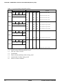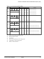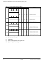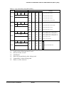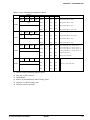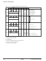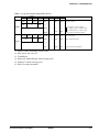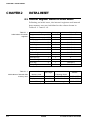
1
CHAPTER 4: PERIPHERAL CIRCUITS AND OPERATION (Input Ports)
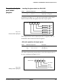
Input comparison
registers and interrupt function
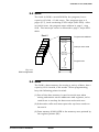
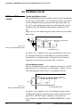
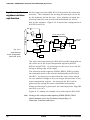
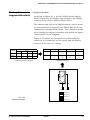
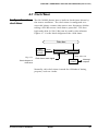
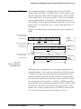
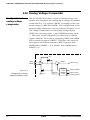
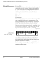
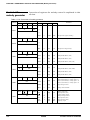
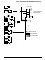
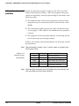
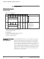
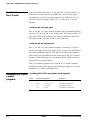
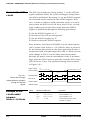
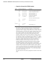
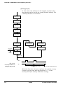
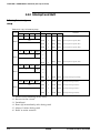
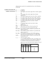
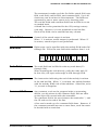
All five input port bits (K00–K03, K10) provide the interrupt
function. The conditions for issuing an interrupt can be set
by the software for the five bits. Also, whether to mask the
interrupt function can be selected individually for all five
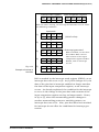
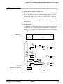
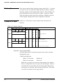
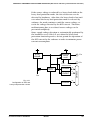
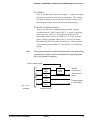
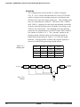
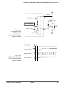
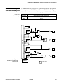
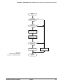
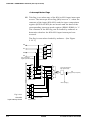
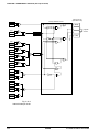
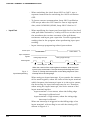
bits by the software. Figure 4.3.2 shows the configuration of
K00–K03 and K10.
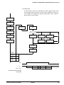
Kxx
One for each pin series
Data bus
Address
Input comparison
register (KCP)
Noise
rejector
Interrupt factor
flag (IK)
Address
Fig. 4.3.2
Interrupt
request
Address
Mask option
(K00–K03, K10)
Interrupt mask
register (EIK)
Input interrupt
circuit configuration
(K00–K03, K10)
Address
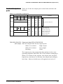
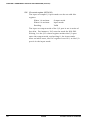
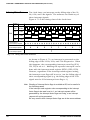
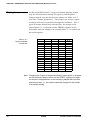
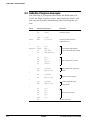
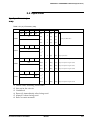
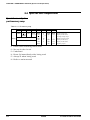
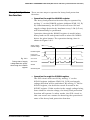
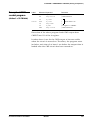
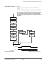
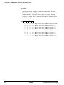
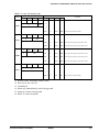
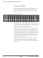
The input interrupt timing for K00–K03 and K10 depends on
the value set in the input comparison registers (KCP00–
KCP03 and KCP10). An interrupt can be set to occur on the
rising or falling edge of the input.
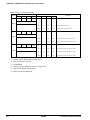
The interrupt mask registers (EIK00–EIK03, EIK10) enable
the interrupt mask to be selected individually for K00–K03
and K10. An interrupt occurs when the input value which
are not masked change so they no longer match those of the
input comparison register. An interrupt for K10 can be
generated by setting the same conditions individually.
When an interrupt is generated, the interrupt factor flag (IK0
and IK1) is set to 1.
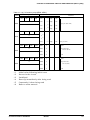
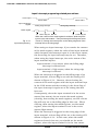
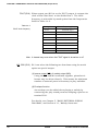
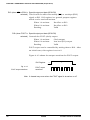
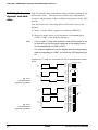
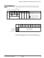
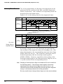
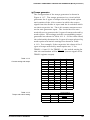
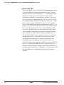
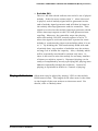
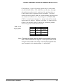
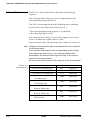
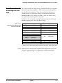
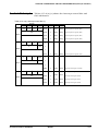
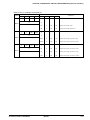
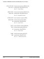
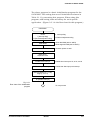
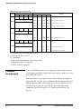
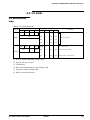
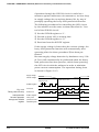
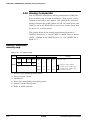
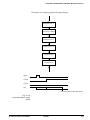
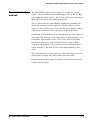
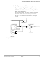
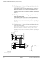
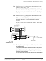
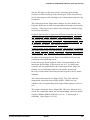
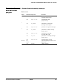
Figure 4.3.3 shows an example of an interrupt for K00–K03.
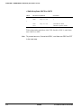
Note Writing to the interrupt mask registers (EIK00–EIK03, EIK10)
should be done only in the DI status (interrupt flag = 0).
Otherwise, it causes malfunction.
I-28
EPSON
S1C62N82 TECHNICAL HARDWARE