1
Net-2000-VCU
Voice Codec Unit
Users Manual
Version 4.0
December, 2013
DVSI Confidential Proprietary
Net-2000™ VCU Users Manual
Version 4.0, December, 2013
Net-2000™ VCU
Users Manual
Version 4.0
December, 2013
(The most up to date version of the manual is always available at www.dvsinc.com)
Copyright, 2008 Digital Voice Systems, Inc
234 Littleton Road
Westford, MA 01886
This document may not, in whole or in part be copied, photocopied, reproduced, translated, or reduced to any
electronic medium or machine readable form without prior consent in writing from Digital Voice Systems,
Incorporated.
Every effort has been made to ensure the accuracy of this manual. However, Digital Voice Systems, Inc. makes no
warranties with respect to the documentation and disclaims any implied warranties of merchantability and fitness for
a particular purpose. Digital Voice Systems, Inc. shall not be liable for any errors or for incidental or consequential
damages in connection with the furnishing, performance, or use of this manual or the examples herein. This includes
business interruption and/or other loss which may arise from the use of this product. The information in this
document is subject to change without notice.
Trademarks
Net-2000™ VCU is a registered trademark of Digital Voice Systems, Inc. Other product names mentioned may be
trademarks or registered trademarks of their respective companies and are the sole property of their respective
manufacturers.
All Rights Reserved
Data subject to change
Page ii
(Subject to Change)
DVSI CONFIDENTIAL PROPRIETARY
Net-2000™ VCU Users Manual
Version 4.0, December, 2013
Net-2000™ VCU END USER License Agreement
3. Transfer of License
1. Preliminary Statements and Definitions
1.1 This nonexclusive end user product license agreement is a legal agreement
between the customer (the END USER) and Digital Voice Systems, Inc.
(DVSI) covering the terms and conditions under which DVSI's proprietary
content (that may consist of and is not limited to software, hardware,
documentation and other material) is licensed to the END USER as part of this
PRODUCT.
a) The PRODUCT shall mean the Hardware, Software, Documentation and other
materials that were provided by DVSI, either directly or indirectly through
distributors or agents, to END USER as part of a sale, delivery or other
transaction.
3.1 The END USER shall have the right to transfer the rights under this
Agreement to a third party by either (i) providing the third party with a copy of
this Agreement or (ii) providing the third party with an agreement written by the
END USER ( hereinafter “END USER Agreement”) so long as the END USER
Agreement is approved in writing by DVSI prior to transfer of the PRODUCT.
The END USER Agreement shall contain comparable provisions to those
contained herein for protecting the Proprietary Information from disclosure by
such third party. Third parties shall agree to accept all the terms and
conditions under either Agreement or the END USER Agreement.
4. Term and Termination
b) Hardware can be in the form of Integrated Circuits (such as Digital signal
Processors) Circuit boards and electronics enclosed in a chassis. DVSI’s Net2000™ VCU is an example of electronics enclosed in a chassis.
4.1 This Agreement is effective upon initial delivery of the PRODUCT and shall
remain in effect until terminated in accordance with this agreement.
c) Software can be in form of computer code, firmware masked into an IC or
stored or embedded into ROM or RAM or Flash memory, or software stored
on any media (such as CD-ROM, floppy disk, hard drive, solid-state memory
or the Internet)
4.2 This Agreement shall terminate automatically without notice from DVSI if END
USER fails to comply with any of the material terms and conditions herein.
END USER may terminate this Agreement at any time upon written notice to
DVSI certifying that END USER has complied with the provisions of Section 3.
d) Documentation means written or electronic information, including user
manuals, technical documents, training materials, specifications or diagrams,
that pertain to or are delivered with the PRODUCT in any manner (including in
print, on CD-ROM, or on-line).
4.3 Upon termination of this Agreement for any reason, END USER shall: (i)
return the PRODUCT and documentation purchased or acquired, or in
Licensee’s possession, to DVSI; (ii) have no further rights to any DVSI
Software or the Technology without a separate written license from DVSI; (iii)
discontinue all use of the PRODUCT;
1.2 DVSI has developed a number of voice coding methods and algorithms (the
“Technology”) which include DVSI’s Advanced Multi-Band Excitation
(“AMBE”) , AMBE+™, and AMBE+2™ voice coders. The Technology codes
speech at low bit rates and may include error correction, echo cancellation and
other auxiliary functions.
1.3 "DVSI Voice Compression Software" shall mean the voice coding Software
that implements or embodies the Technology and is embedded into or
otherwise provided with the PRODUCT.
1.4 "DVSI Voice Codec" shall mean the DVSI Voice Compression Software, any
PRODUCT Hardware into which the DVSI Voice Compression Software is
embedded or executed and any associated Documentation.
1.5 DVSI represents that it owns certain “Proprietary Rights” in the PRODUCT
including patent rights, copyrights, trademarks and trade secrets. These rights
include one or more of the following US Patents #5,630,011; #5,649,050;
#5,701,390; #5,715,365; #5,754,974; #5,826,222; #5,870,405; #6,161,089;
#6,199,037; #6,912,495; #7,634,399; #7,957,963; #7,970,606; #8,036,886;
#8,200,497; #8,315,860 and #8,359,197; and under other US and foreign
patents and patents pending. AMBE, AMBE+™ and AMBE+2™ are
trademarks of Digital Voice Systems, Inc.
1.6 “END USER” shall mean the person and/or organization to whom the DVSI
Vocoder Product (software or hardware) was delivered or provided to as
specified in the purchase order or other documentation. In the event that the
END USER transfers his rights under this license to a third party as specified
in Section 3.0, then this third party shall become an “END USER”.
1.7 DVSI reserves the right to make modifications and other changes to its
products and services at any time and to discontinue any product or service
without notice.
All confidentiality obligations of Customer and all limitations of liability and
disclaimers and restrictions of warranty shall survive termination of this
Agreement. In addition, the provisions of the sections titled "U.S. Government
End User Purchasers" and "General Terms Applicable to the Limited Warranty
Statement and End User License" shall survive termination of this Agreement.
5. Payments
5.1 In consideration of the materials delivered as part of the Product, and in
consideration of the license granted by DVSI for the PRODUCT, and in
consideration of DVSI's performance of its obligations hereunder, the END
USER agrees to pay to DVSI the fees as specified in DVSI's invoice.
Payments of fees shall be received by DVSI prior to shipment of the
PRODUCT.
6. Proprietary Notices
6.1 END USER shall maintain and not remove any copyright or proprietary notice
on or in the PRODUCT.
6.2 Reproduction of non-proprietary information found in DVSI Users Manuals or
data sheets is permissible only if the END USER reproduces without
alteration, and includes all copyright and other proprietary notices, all
associated warranties, conditions and limitations on all copies, in any form.
7. Proprietary Information
7.1 The parties agree that the PRODUCT shall be considered Proprietary
Information.
7.2 Except as otherwise provided in this Agreement, END USER shall not use,
disclose, make, or have made any copies of the Proprietary Information, in
whole or in part, without the prior written consent of DVSI.
2. License Granted
8. Limited Warranty
2.1 Subject to the conditions herein and upon initial use of the DVSI Product,
DVSI hereby grants to END USER a non-exclusive, limited license to use the
DVSI Voice Compression Software and Technology within the PRODUCT.
No license is granted for any use of the DVSI Voice Compression Software or
Technology on any other device or Hardware or in any manner other than
within the original unmodified PRODUCT purchased from DVSI. No license is
granted to copy or modify the DVSI Voice Compression Software or the
PRODUCT either in whole or in part.
2.2 No license, right or interest in any trademark, trade name or service mark of
DVSI is granted under this Agreement. END USER acknowledges that the
PRODUCT may contain trade secrets of DVSI, including but not limited to the
specific design, and associated interface information.
2.3 END USER shall not copy, extract, reverse engineer, disassemble, decompile or otherwise reduce the DVSI Voice Compression Software to humanreadable form. END USER shall not alter, duplicate, make copies of, create
derivative works from, distribute, disclose, provide or otherwise make available
to others, the DVSI Voice Compression Software and Technology and/or trade
secrets contained within the PRODUCT in any form to any third party without
the prior written consent of DVSI. The END USER shall implement reasonable
security measures to protect such trade secrets.
2.4 This is a license, not a transfer of title, to the DVSI Voice Compression
Software, Technology and Documentation, and DVSI retains ownership and
title to all copies.
8.1 DVSI warrants the PRODUCT to be free from defects in materials and
workmanship under normal use for a period of ninety (90) days from the date
of delivery. The date of delivery is set forth on the packaging material in which
the Product is shipped. This limited warranty extends only to the Customer
who is the original purchaser. If the PRODUCT is found to be defective and
the condition is reported to DVSI, within the warranty period, DVSI may, at its
option, repair, replace, or refund of the purchase price of the PRODUCT.
DVSI may require return of the PRODUCT as a condition to the remedy.
Restrictions. This warranty does not apply if the Product (a) has been altered,
(b) has not been installed, operated, repaired, or maintained in accordance
with instructions supplied by DVSI, (c) has been subjected to abnormal
physical or electrical stress, misuse, negligence, or accident;
8.2 Except as stated in Section 8.1, the PRODUCT is provided "as is" without
warranty of any kind. DVSI does not warrant, guarantee or make any
representations regarding the use, or the results of the use, of the PRODUCT
with respect to its correctness, accuracy, reliability, speech quality or
otherwise. The entire risk as to the results and performance of the PRODUCT
is assumed by the END USER. After expiration of the warranty period, END
USER, and not DVSI or its employees, assumes the entire cost of any
servicing, repair, replacement, or correction of the PRODUCT.
8.3 DVSI represents that, to the best of its knowledge, it has the right to enter into
this Agreement and to grant a license to use the PRODUCT to END USER.
Page iii
(Subject to Change)
DVSI CONFIDENTIAL PROPRIETARY
Net-2000™ VCU Users Manual
Version 4.0, December, 2013
8.4 Except as specifically set forth in this Section 8, DVSI makes no express or
implied warranties including, without limitation, the warranties of
merchantability or fitness for a particular purpose or arising from a course of
dealing, usage or trade practice, with respect to the PRODUCT. Some states
do not allow the exclusion of implied warranties, so the above exclusion may
not apply to END USER. No oral or written information or advice given by
DVSI or its employees shall create a warranty or in any way increase the
scope of this warranty and END USER may not rely on any such information
or advice. The limited warranties under this Section 8 give END USER
specific legal rights, and END USER may have other rights which vary from
state to state.
9. Limitation of Liability
The END USER agrees that the limitations of liability and disclaimers set forth
herein will apply regardless of whether the END USER has accepted the
product or service delivered by DVSI.
9.1 In no event shall DVSI be liable for any special, incidental, indirect or
consequential damages resulting from the use or performance of the
PRODUCT whether based on an action in contract, or for applications
assistance, or product support, or tort (including negligence) or otherwise
(including, without limitation, damages for loss of business revenue, profits,
business interruption, and loss of business information or lost or damaged
data), even if DVSI or any DVSI representative has been advised of the
possibility of such damages.
9.2 Because some states or jurisdictions do not allow the exclusion or limitation of
liability for consequential or incidental damages, the above limitations may not
apply to END USER.
9.3 DVSI's maximum liability for damages arising under this Agreement shall be
limited to 20% (twenty percent) of the fees paid by END USER for the
particular PRODUCT that gave rise to the claim or that is the subject matter of,
or is directly related to, the cause of action.
10. Taxes
10.1 All payments required under Section 4 or otherwise under this Agreement
are exclusive of taxes and END USER agrees to bear and be responsible for
the payment of all such taxes (except for taxes based upon DVSI's income)
including, but not limited to, all sales, use, rental receipt, personal property or
other taxes which may be levied or assessed in connection with this
Agreement.
11. Export
11.1 United States export laws and regulations prohibit the exportation of certain
products or technical data received from DVSI under this Agreement to certain
countries except under a special validated license. Some of the restricted
countries include: Libya, Cuba, North Korea, Iraq, Serbia, Taliban in
Afghanistan, Sudan, Burma, and Iran. The END USER hereby gives its
assurance to DVSI that it will not knowingly, unless prior authorization is
obtained from the appropriate U.S. export authority, export or re-export,
directly or indirectly to any of the restricted countries any products or technical
data received from DVSI under this Agreement in violation of said United
States Export Laws and Regulations. DVSI neither represents that a license is
not required nor that, if required, it will be issued by the U.S. Department of
Commerce. Licensee shall assume complete and sole responsibility for
obtaining any licenses required for export purposes.
12. Governing Law
12.1 This Agreement is made under and shall be governed by and construed in
accordance with the laws of the Commonwealth of Massachusetts, (USA),
except that body of law governing conflicts of law. If any provision of this
Agreement shall be held unenforceable by a court of competent jurisdiction,
that provision shall be enforced to the maximum extent permissible, and the
remaining provisions of this Agreement shall remain in full force and effect.
This Agreement has been written in the English language, and the parties
agree that the English version will govern.
Page iv
(Subject to Change)
DVSI CONFIDENTIAL PROPRIETARY
Net-2000™ VCU Users Manual
Version 4.0, December, 2013
Table of Contents
1
2
3
4
NET-2000™ VOICE CODEC UNIT INTRODUCTION ..................................................... 1
1.1
Features..................................................................................................................................1
1.2
Interfaces ................................................................................................................................1
1.3
Net-2000™-VCU modes of operation ....................................................................................2
1.4
Control ....................................................................................................................................2
1.5
Protocol...................................................................................................................................2
NET-2000™ VCU INSTALLATION.................................................................................. 3
2.1
Set Up.....................................................................................................................................3
2.2
Net-2000™-VCU Connections ...............................................................................................3
2.2.1 Connecting AC Power......................................................................................................... 3
2.2.2 Voice Audio I/O Connections.............................................................................................. 4
2.2.3 Channel Communication..................................................................................................... 4
2.3
Rack Mount Installation ..........................................................................................................6
2.4
VCU Front Panel ....................................................................................................................6
2.4.1 Power On Switch................................................................................................................. 7
2.5
Initial Set-up – (RS-232 Serial Connection) ...........................................................................7
NET-2000™ VCU CONTROL .......................................................................................... 9
3.1
Net-2000™-VCU Control Via Web Interface ..........................................................................9
3.2
Navigation Menu...................................................................................................................10
3.2.1 VOIP Mode ....................................................................................................................... 10
3.2.2 File Mode .......................................................................................................................... 10
3.2.3 Network Settings Page ...................................................................................................... 11
3.3
Status Control Bar ................................................................................................................12
3.3.1 Net-2000™- is Idle............................................................................................................ 12
3.3.2 Net-2000™- is Active ........................................................................................................ 12
3.3.3 Start and Stop Buttons....................................................................................................... 13
3.4
Reset to Defaults Button.......................................................................................................13
3.5
Version Identification ............................................................................................................13
3.6
Hyperlink to DVSI Web Page ...............................................................................................13
3.7
VCU Control via Serial Interface ..........................................................................................13
VOIP MODE ................................................................................................................... 16
4.1
Net-2000™-VCU VOIP Mode Settings.................................................................................16
4.2
Vocoder Selection (Version Dependant) ..............................................................................17
4.2.1 Forward Error Correction (FEC)..................................................................................... 17
4.3
APCO Vocoder Version – APCO Standard and APCO Enhanced ......................................17
4.3.1 APCO Enhanced Vocoder Bit Stealing ............................................................................. 18
4.3.2 APCO Enhanced Vocoder Additional Features ................................................................ 18
4.4
AMBE® / AMBE+™ Vocoders Version ................................................................................19
4.5
AMBE+2™ Vocoder Version ................................................................................................20
4.6
Vocoder Selection (GMR-1 or GMR-2 Version) ...................................................................20
4.6.1 GMR-1 Vocoder Selection................................................................................................. 20
4.6.2 GMR-2 Vocoder Selection................................................................................................. 21
Page v
(Subject to Change)
DVSI CONFIDENTIAL PROPRIETARY
Net-2000™ VCU Users Manual
Version 4.0, December, 2013
4.7
BGAN Vocoder Selection .....................................................................................................21
4.8
GMR-2+ Vocoder Selection..................................................................................................21
4.8.1 Rate “Bit Steal 1 Bit”........................................................................................................ 22
4.9
Vocoder Options Configuration ............................................................................................22
4.9.1 Voice Activation Detection (VAD) .................................................................................... 22
4.9.2 Tone Detector.................................................................................................................... 23
4.9.3 Noise Suppressor............................................................................................................... 23
4.9.4 Echo Canceller (Echo) ...................................................................................................... 23
4.9.5 DTX (BGAN and GMR-2+ Vocoders Only)...................................................................... 24
4.9.6 Automatic Gain Control (APCO Enhanced Vocoder Only) .............................................. 24
4.9.7 High Pitch Detection Feature (GMR-2+ Vocoder Only).................................................. 24
4.10 Source Selection ..................................................................................................................25
4.10.1 Voice Source ..................................................................................................................... 25
4.10.2 Output Gain....................................................................................................................... 26
4.10.3 2-Wire Wait on Ring.......................................................................................................... 26
4.10.4 DTMF Panel ..................................................................................................................... 26
4.11 Channel Settings ..................................................................................................................27
4.11.1 Channel Source Selection.................................................................................................. 28
4.11.2 Target IP Address ............................................................................................................. 29
4.11.3 Port Number...................................................................................................................... 29
5
6
7
FILE MODE .................................................................................................................... 30
5.1
Vocoder Type Selection .......................................................................................................30
5.2
Channel Selection Port Number ...........................................................................................32
5.3
Processing Files with the Net-2000™-VCU Software ..........................................................33
5.4
FILE Mode PC-executable Program ....................................................................................33
5.4.1 EXAMPLE (encode):......................................................................................................... 34
5.4.2 EXAMPLE (decode):......................................................................................................... 35
INTERFACE PROTOCOL.............................................................................................. 36
6.1
Serial Port Protocol...............................................................................................................36
6.2
Ethernet Protocol..................................................................................................................36
6.3
Packet Protocol Description .................................................................................................36
6.3.1 Packet Header................................................................................................................... 37
6.3.2 Channel Data Packet ........................................................................................................ 38
6.3.3 Voice Data Packet............................................................................................................. 49
6.3.4 Reset Packet ...................................................................................................................... 54
6.3.5 Ack Packet......................................................................................................................... 56
6.3.6 Nack Packet....................................................................................................................... 58
VCU SPECIFICATIONS................................................................................................. 61
7.1
Rear Panel Connections.......................................................................................................61
7.2
Audio I/O Connections..........................................................................................................62
7.3
Electrical Input ......................................................................................................................63
7.4
Mechanical............................................................................................................................63
7.5
Environmental.......................................................................................................................63
8
UPGRADE PROCEDURE.............................................................................................. 64
9
SUPPORT ...................................................................................................................... 65
9.1
DVSI Technical Support .......................................................................................................65
Page vi
(Subject to Change)
DVSI CONFIDENTIAL PROPRIETARY
Net-2000™ VCU Users Manual
Version 4.0, December, 2013
10
HISTORY OF REVISIONS ............................................................................................. 66
11
NOTES ........................................................................................................................... 67
List of Figures
Figure 1 Net-2000™-VCU Rear Panel.......................................................................................................... 3
Figure 2 Connecting to an Ethernet Network................................................................................................ 5
Figure 3 Connect two Net-2000™-VCU via RS-422..................................................................................... 5
Figure 4 Rack Mount Installation .................................................................................................................. 6
Figure 5 Net-2000™-VCU Front Panel ......................................................................................................... 6
Figure 6 Net-2000™-VCU Page ................................................................................................................... 9
Figure 7 Navigation Menu ........................................................................................................................... 10
Figure 8 Example Setup for VOIP Mode..................................................................................................... 10
Figure 9 Example Setup for File Mode ....................................................................................................... 11
Figure 10 Net-2000™-VCU Network Settings Window .............................................................................. 11
Figure 11 Net-2000™ VCU Status.............................................................................................................. 12
Figure 12 Net-2000™- VOIP Settings......................................................................................................... 16
Figure 13 Vocoder Type and Rate Selection .............................................................................................. 17
Figure 14 APCO Standard Vocoder Selection............................................................................................ 18
Figure 15 APCO Enhanced Vocoder Selection .......................................................................................... 18
Figure 16 AMBE® / AMBE+™ Vocoder Type and Rate Selection ............................................................. 19
Figure 17 GMR-1 Vocoder Selection .......................................................................................................... 20
Figure 18 GMR-2 Vocoder Selection .......................................................................................................... 21
Figure 19 BGAN Vocoder Selection ........................................................................................................... 21
Figure 20 GMR-2+ Vocoder Selection ........................................................................................................ 21
Figure 21 Vocoder Options ......................................................................................................................... 22
Figure 22 Voice Source Selection............................................................................................................... 25
Figure 23 Output Gain Selection................................................................................................................. 26
Figure 24 DTMF Key Pad ........................................................................................................................... 27
Figure 25 Channel Source .......................................................................................................................... 28
Figure 26 Channel Source Selections ........................................................................................................ 28
Figure 27 File Mode Web Page .................................................................................................................. 30
Figure 28 AMBE® / AMBE+™ Version File Mode Selection ...................................................................... 30
Figure 29 APCO Version File Mode Selection............................................................................................ 31
Figure 30 GMR-1 Version File Mode Selection .......................................................................................... 31
Figure 31 GMR-2 Version File Mode Selection .......................................................................................... 32
Figure 32 BGAN and GMR-2+ Version File Mode Selection...................................................................... 32
Figure 33 RS-422 Asynchronous Pin 1....................................................................................................... 62
List of Tables
Table 1 Rear Panel Connectors.................................................................................................................... 3
Table 2 Serial Port Terminal Set-up.............................................................................................................. 7
Table 3 DHCP Set-up command Arguments ................................................................................................ 7
Table 4 DHCP Setup Example...................................................................................................................... 8
Table 5 AMBE+2™ Vocoder Data Rate Selection...................................................................................... 20
Table 6 DTMF Data..................................................................................................................................... 26
Table 7 cmode default values ..................................................................................................................... 34
Table 8 Packet Header ............................................................................................................................... 37
Table 9 len Header Parameter.................................................................................................................... 37
Table 10 type Header Parameter................................................................................................................ 38
Table 11 seq Header Parameter................................................................................................................. 38
Table 12 Channel Data Packet ................................................................................................................... 39
Table 13 len Header Parameter.................................................................................................................. 40
Page vii
(Subject to Change)
DVSI CONFIDENTIAL PROPRIETARY
Net-2000™ VCU Users Manual
Version 4.0, December, 2013
Table 14 type Header Parameter................................................................................................................ 40
Table 15 seq Header Parameter................................................................................................................. 40
Table 16 rate[0-5] Parameter ...................................................................................................................... 41
Table 17 AMBE® / AMBE+™ / AMBE+2™ Rate Table............................................................................. 43
Table 18 APCO Standard and APCO Enhanced Rate Table .................................................................... 43
Table 19 GMR-1 and GMR-2 Rate Table .................................................................................................. 43
Table 20 BGAN and GMR-2+ Rate Table ................................................................................................. 44
Table 21 Rate Tables Key........................................................................................................................... 44
Table 22 cmode Parameter (Used in the Decoder Command Packet) ...................................................... 44
Table 23 cmode Parameter (Used in the Channel Response Packet)....................................................... 45
Table 24 tone.idx Parameter....................................................................................................................... 46
Table 25 tone.idx Parameter (cont’d).......................................................................................................... 47
Table 26 tone.amp Parameter .................................................................................................................... 48
Table 27 ws Parameter ............................................................................................................................... 48
Table 28 format Parameter ......................................................................................................................... 48
Table 29 channel Parameter....................................................................................................................... 49
Table 30 Voice Data Packet........................................................................................................................ 50
Table 31 len Header Parameter.................................................................................................................. 51
Table 32 type Header Parameter................................................................................................................ 51
Table 33 seq Header Parameter................................................................................................................. 51
Table 34 cmode Parameter (Used in the Encoder Command Packet) ...................................................... 52
Table 35 cmode Parameter (Used in the Voice Response Packet) ........................................................... 52
Table 36 ws Parameter ............................................................................................................................... 53
Table 37 format Parameter ......................................................................................................................... 53
Table 38 voice Parameter ........................................................................................................................... 53
Table 39 Reset Packet................................................................................................................................ 54
Table 40 len Header Parameter.................................................................................................................. 54
Table 41 type Header Parameter................................................................................................................ 55
Table 42 seq Header Parameter................................................................................................................. 55
Table 43 which Parameter .......................................................................................................................... 55
Table 44 Ack Packet ................................................................................................................................... 56
Table 45 len Header Parameter.................................................................................................................. 56
Table 46 type Header Parameter................................................................................................................ 57
Table 47 seq Header Parameter................................................................................................................. 57
Table 48 cmd parameter ............................................................................................................................. 57
Table 49 Nack Packet ................................................................................................................................. 58
Table 50 len Header Parameter.................................................................................................................. 58
Table 51 type Header Parameter................................................................................................................ 59
Table 52 seq Header Parameter................................................................................................................. 59
Table 53 cmd Parameter............................................................................................................................. 59
Table 54 reason Parameter ........................................................................................................................ 60
Table 55 Serial Port Pin Outs...................................................................................................................... 61
Table 56 RS-422 Synchronous Serial Port Pin Outs .................................................................................. 61
Table 57 RS-422 Asyncronous Serial Port Pin Outs .................................................................................. 62
Page viii
(Subject to Change)
DVSI CONFIDENTIAL PROPRIETARY
Digital Voice Systems, Inc.
The Speech Compression Specialists
Net-2000™ VCU Users Manual
Version 4.0, December, 2013
Net-2000™-Voice Codec Unit
1 Net-2000™ Voice Codec Unit Introduction
The Net-2000™ Voice Codec Unit (VCU) incorporates Digital Voice Systems, Inc. (DVSI) latest advancement in
voice compression technology to bridge analog speech I/O to an Ethernet network. There are various versions of the
Net-2000™-VCU that support a variety of vocoders used in voice compression digital communication systems.
The basic operation and control of Net-2000™-VCU is the same for all versions. This manual includes information
on all versions of the Net-2000™-VCU. Differences between versions are separated so that the user needs only to
refer to the sections that pertain to the specific Net-2000™ VCU purchased.
The Net-2000™-VCU contains several interfaces for flexibility in speech input and output including Ethernet and
RS-422 as a channel data interfaces. The Net-2000™-VCU speech I/O can operate in full duplex for real time
communication or in half duplex mode voice recording or other storage applications. The speech I/O is easily
managed with the Net-2000™-VCU built-in web server control.
1.1
Features
1.2
Real-time, full-duplex communications via the Ethernet interface to another Net-2000™-VCU unit.
A built-in web server for easy selection and control of the audio I/O
The Net-2000™-VCU’s RS-232 serial port can be used as a console terminal to allow low-level system
setup.
The Net-2000™-VCU can handle information from a DHCP server when available on a Local Area
Network (LAN).
Encode/Decode files across a LAN to and from a PC
The embedded user interface allows the operation software to be field upgradeable.
Both voice and channel data can be transmitted over the Ethernet interface at the same time.
Interfaces
To meet a wide variety of communication system requirements the Net-2000™-VCU contains three interfaces for
speech input and output and two for channel data. The Net-2000™-VCU’s analog interfaces includes a 4-wire, a
handset and a 2-wire for input and output of uncompressed speech. Control of these interfaces are easily managed
with the Net-2000™-VCU’s built-in web server.
The Net-2000™-VCU provides a RS-422 interface and 10Base- Ethernet interface as a channel connection. The
RS-422 allows two Net-2000™-VCUs to be connected together. By providing both an asynchronous or synchronous
connecting the Net-2000™-VCU offers the flexibility of connecting to some other RS-422 device. Using the
10Base- Ethernet interface the Net-2000™-VCU can also be connected directly to a Local Area Network (LAN).
This configuration can be used to create a real-time full duplex Voice Over Internet Protocol (VOIP) Ethernet based
vocoder communication system between two Net-2000™-VCUs. Alternatively, the Net-2000™-VCU can
Loopback the VOIP information back to itself for voice monitoring and evaluation applications.
When two Net-2000™-VCU communicate, each converts the input analog speech into digital speech samples,
encodes the speech using the selected vocoder mode and then sends the compressed bit stream out over Ethernet as
UDP packets or RS-422. Simultaneously, the compressed bit stream of UDP packets from the other Net-2000™VCU are read in from the selected interface and decoded back in to digital speech samples. The decoded samples
are converted back into analog speech via the AIC-10 codec whose output is sent to both the handset and line-level
output connections.
Page 1
(Subject to Change)
DVSI CONFIDENTIAL PROPRIETARY
Net-2000™ VCU Users Manual
Version 4.0, December, 2013
1.3
Net-2000™-Voice Codec Unit
Net-2000™-VCU modes of operation
The Net-2000™-VCU provides the user with two modes of operation VOIP Mode and File Mode. To provide full
duplex real-time communication, the Net-2000™-VCU can channel the compressed bit stream through either the
RS-422 or the Ethernet interfaces to another Net-2000™-VCU.
Alternatively, in File mode the Net-2000™-VCU can Encode/Decode files stored on a PC on the LAN for non-realtime testing and evaluation. The Net-2000™-VCU remains in an idle state until it gets a command to start and stop
processing (encoding and/or decoding) data that is being sent.
1.4
Control
When connected on a LAN — any PC on the network can use a standard web browser to control the Net-2000™VCU through the use of a PC web browser. The user-friendly web pages built-into the Net-2000™-VCUmake it
easy to select analog audio interfaces, select the vocoder mode and to establish real-time, full-duplex communication
across the Ethernet connection. In addition to the control, the web pages display information about network settings,
operating mode and system status. Since the Net-2000™-VCUuses Ethernet, its web page can even be accessed
over a wireless network through a wireless notebook or tablet PC.
The Net-2000™-VCUcan also be controlled via PC connected to the RS-232 interface. Connecting to the RS-232
interface allows for both low level set-up of the NET-2000™-VCU and for control using ASCII commands. Input
and output gain settings for the voice codec can be also specified.
1.5
Protocol
The Net-2000™-VCU uses DVSI’s own UDP interface described in Section 4. This allows users to develop their
own application controls and user interfaces for an endless array of customized applications.
Before using the Net-2000™-VCU, read through this user’s manual in its entirety.
Page 2
(Subject to Change)
DVSI CONFIDENTIAL PROPRIETARY
Digital Voice Systems, Inc.
The Speech Compression Specialists
Net-2000™ VCU Users Manual
Version 4.0, December, 2013
Net-2000™-VCU Installation
2 Net-2000™ VCU Installation
The Net-2000™-VCU hosts a variety of inputs and outputs that provide flexibility in system
integration. The Net-2000™-VCU is designed to be controlled through an Ethernet Interface or an RS-232 serial
interface with the communication channel interface using the RS-422 serial port or the Ethernet network. This
manual assumes that the user has a working networked PC before the Net-2000™-VCU is installed.
2.1
Set Up
Initial set-up of the Net-2000™-VCU is fast and straightforward. The Ethernet interface is equipped to handle IP
address information from a DHCP server making network installation routine. Alternatively, the RS-232 serial port
can be used via telnet as a console terminal to allow low-level network setup.
2.2
Net-2000™-VCU Connections
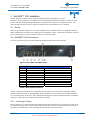
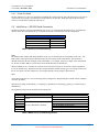
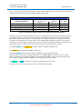
See VCU Specifications for more detailed technical information about each of the connections.
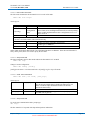
Figure 1 Net-2000™-VCU Rear Panel
Rear Panel Connections
Item No. Name
1
Serial Port
2
LAN
3
RS-422 Synchronous
4
RS-422 Asynchronous
5
2 Wire I/O
6
Analog Line In
7
Analog Line Out
8
Handset
9
AC Line In
Connector Type
DE9s
RJ-45
DB-15HD
RJ-45
RJ-11
RCA Jack
RCA Jack
RJ-11
Power Cord Receptacle
Table 1 Rear Panel Connectors
In order to install the Net-2000™-VCU connections must be made to a voice audio source and output, channel
communications and control. In Target IP Mode, the Net-2000™-VCU can be connected to another Net-2000™VCU located anywhere on the LAN. This configuration can support a real-time, full-duplex channel over Ethernet
connection. This mode can be controlled via the built-in web page.
2.2.1
Connecting AC Power
The Net-2000™-VCU unit will automatically adjust to both European and US AC line voltage levels. There are no
user settings. Just plug in the AC power cord provided into the AC receptacle on the back of the unit (See Figure 1
Net-2000™-VCU Rear Panel -- item 9) and plug the other end into an AC power outlet.
Page 3
(Subject to Change)
DVSI CONFIDENTIAL PROPRIETARY
Net-2000™ VCU Users Manual
Version 4.0, December, 2013
2.2.2
2.2.2.1
Net-2000™-VCU Installation
Voice Audio I/O Connections
4-Wire
Connecting the Net-2000™-VCU to analog audio components is fairly self explanatory. A typical connection
would be to connect the audio output of an audio component such as a Mic, a Digital Tape, player or even a PC
sound card output to the Analog Input jack of the Net-2000™-VCU (audio cables not included). Next connect the
Analog Output jack of the Net-2000™-VCU to an amplifier or Audio In jack on a PC sound card.
2.2.2.2
Handset
If the handset connection is to be used instead of the 4-wire interface, connect the standard telephone handset that
was included with the unit to connect to the RJ11 handset connector. This handset has a cord (also included) that is
about a foot long (when not stretched) to help reduce noise from being introduced into the voice signal.
2.2.2.3
2-Wire
The Net-2000™-VCU can be connected to a standard North American POTS line through its 2-wire interface. The
2-wire interface is designed to pick-up the line and be ready to accept analog voice to be encoded and sent across the
designated channel. With the wait on ring feature the Net-2000™-VCU will automatically answer the line when it
receives a call instead of having to keep the line open all the time.
2.2.3
2.2.3.1
Channel Communication
Ethernet
The Net-2000™-VCU implements this channel data interface using a special protocol designed by DVSI. This UDP
streaming mode allows for full-duplex communication to another Net-2000™-VCU box in real time. To run in this
mode the operator selects the voice interface (4-Wire, handset, or 2-Wire) and the Ethernet communications channel
interface. When running in VOIP Mode the VCU encodes a frame of speech from the specified voice interface and
implements a protocol to stream a packet containing a decode command and encoded data to the communications
channel interface. At the same time the VCU expects to receive packets from the communications channel interface
that contains a decode command and encoded data. The VCU decodes and sends this continuous stream to both the
handset and line-out speech outputs.
In File Mode the Net-2000™-VCU responds to incoming voice packets by encoding the voice data in them and
transmitting a channel data packet to the sender, and to incoming channel data packets by decoding them and
transmitting synthesized voice data packets to the sender. Only one user can access the VCU at a time in File Mode.
Transmitting data packets to the VCU from more than one source will produce undesired results.
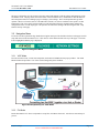
2.2.3.2
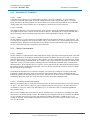
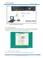
Connecting the Ethernet Network
Make sure the Ethernet cable is connected to the Ethernet port in the back of the NET-2000™-VCU before applying
AC power. Note that if you are going to use a direct Ethernet connection from your PC to the NET-2000™-VCU
you should use a crossover cable. If your NET-2000™-VCU is connected to a hub, a straight-through Ethernet
cable should be used.
The VCU has a 10 Mbps Ethernet interface for network communication. It can operate on a 100 Mbps LAN when
connected to a 10/100 Ethernet hub or router. The default network configuration for the VCU assumes that a DHCP
server is available on the LAN to provide it with valid network address information. If a DHCP server is not
available on the LAN, static IP address information will need to be entered via the serial port in order to access the
VCU over the network.
Page 4
(Subject to Change)
DVSI CONFIDENTIAL PROPRIETARY
Net-2000™ VCU Users Manual
Version 4.0, December, 2013
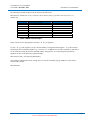
Net-2000™-VCU Installation
Figure 2 Connecting to an Ethernet Network
2.2.3.3
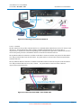
RS-422
The Net-2000 VCU also provides a RS-422 interface as a communications channel between two VCU units or some
other device. The RS-422 interface follows industry standards of differential I/O can be used as either a
Asynchronous or Synchronous connection depending on the communication requirements. Both RS-422 interfaces
use the same packet protocols as the Ethernet interface as described in 6 Interface Protocol.
The Synchronous RS-422 connection is available on the HD-15 connector located on rear panel of the Net-2000™VCU and provides the data clock and 8 bit frames. For pinout detail see Section 5 Table 56 RS-422 Synchronous
Serial Port Pin Outs
The Asynchronous RS-422 connection is available on the RJ45 connector located on rear panel of the Net-2000™VCU and provides the data only in a 8,none, 1 format. . For pinout detail see Section 5 Table 57 RS-422
Asyncronous Serial Port Pin Outs.
Figure 3 Connect two Net-2000™-VCU via RS-422
Page 5
(Subject to Change)
DVSI CONFIDENTIAL PROPRIETARY
Net-2000™ VCU Users Manual
Version 4.0, December, 2013
2.2.3.4
Net-2000™-VCU Installation
Connecting to RS-232
The RS-232 serial port located on the back of the Net-2000™-VCU unit provides low level set-up functions. The
interface itself consists of a simple command/response ASCII text protocol. You can use a terminal or terminal
emulator on a personal computer to type commands at a keyboard as your user interface.
To connect the serial interface, to a Terminal or PC plug a straight-through modem cable (see pin outs in Table 55
Serial Port Pin Outs) into the serial port DE-9s connector and plug the other end into your terminal (or one of the
serial ports on your PC if you are using an emulator). Set the terminal as shown in Table 2 Serial Port Terminal Setup.
2.3
Rack Mount Installation
When a rack mount kit is purchased with the Net-2000™-VCU the assembly is installed at the factory prior to
shipping. If the rack mount, needs to be removed there are three flat head Philips screws on each side that secures
the rack mount plate to the Net-2000™-VCU chassis as shown below. To avoid scratching the sides of the Net2000™-VCU when removing the rack plate push down on the front of the plate so that it slips out from underneath
the unit. When re-installing the rack mount slip it up from underneath and push it back to be flush with front face.
Use the same six screws to secure the rack mount back on the chassis.
Figure 4 Rack Mount Installation
2.4
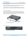
VCU Front Panel
Net - 2000
Digital Voice Systems, Inc.
Voice Codec Unit
Figure 5 Net-2000™-VCU Front Panel
Page 6
(Subject to Change)
DVSI CONFIDENTIAL PROPRIETARY
Net-2000™ VCU Users Manual
Version 4.0, December, 2013
2.4.1
Net-2000™-VCU Installation
Power On Switch
The Net-2000™-VCU’s power is turned ON /Off through the switch on the left side of the front panel. Press the top
of the switch (I) to turn ON. Press the bottom of the switch (0) to turn OFF. When powering off the unit always
wait a few seconds before turning the unit back on.
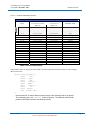
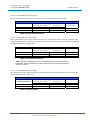
2.5
Initial Set-up – (RS-232 Serial Connection)
The RS-232 interface is used for command line style set-up. It is used when the Net-2000™-VCU is installed on a
network where there is no DHCP Server or when the user wants to customize the network configuration.
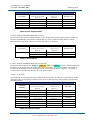
Serial Port Settings
Bits per second:
Data bits:
Parity:
Stop bits:
Flow control:
9600
8
None
1
None
Table 2 Serial Port Terminal Set-up
Note:
The Ethernet MAC address and default hostname of the VCU is derived from the serial number of the VCU. The
MAC address will begin with 00:01:FD followed by the last six digits of the serial number. The hostname is
NET2K followed by the last four digits of the serial number. For example, if the last six digits of the serial number
are 301234, the MAC address is 00:01:FD:30:12:34 and the hostname is NET2K1234.
When no DHCP server is available on a LAN the VCU’s RS-232 serial port can be used as a console terminal for
low-level network setup. With the serial cable connected and the terminal running type a few carriage returns from
the PC’s keyboard. The Net-2000™-VCU will respond with the console prompt as shown below:
adsh>
At the adsh prompt the VCU’s network settings can be configured or changed using the terminal console command
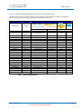
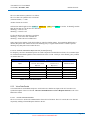
“network” as follows:
adsh>network [-dhcp] [-h hostname] [-w workgroup] [-i ipaddress] [-m netmask] [-g gateway] [-n nameserver][-d
domainname]
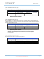
The arguments to the network command are described below:
Arguments
-dhcp
-h
-w
-i
-m
-g
-n
-d
Use
when DHCP is available on LAN
anytime
use only when DHCP is disabled
Result
DHCP is enabled
Sets the hostname of the VCU
Sets the Windows workgroup of the VCU
Sets the static IP address
Sets the IP address of the netmask
Sets the IP address of the gateway
Sets the IP address of the nameserver
Sets the domain name of the VCU.
Table 3 DHCP Set-up command Arguments
Page 7
(Subject to Change)
DVSI CONFIDENTIAL PROPRIETARY
Net-2000™ VCU Users Manual
Version 4.0, December, 2013
Net-2000™-VCU Installation
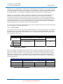
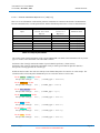
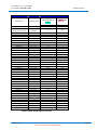
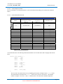
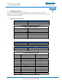
The following command example results are shown in the table below
adsh>network –h net2k1234 -w lab -i 192.168.1.100 -m 255.255.255.0 -g 192.168.1.250 -n 192.168.1.1 -d
domain.com
Arguments
-h
-w
-i
-m
-g
-n
-d
VCU Result
DHCP is NOT enabled
HOSTNAME
Windows WORKGROUP
STATIC IP address
NETMASK IP address
GATEWAY IP address
NAMESERVER IP address
VCU DOMAIN NAME
Example
net2k1234
lab
192.168.1.100
255.255.255.0
192.168.1.250
192.168.1.1
domain.com
Table 4 DHCP Setup Example
NOTE: Do not mix the -dhcp argument with the -i -m –d -g -n arguments.
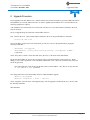
Use the -i -m -g -n and -d options to set up a static IP address. The argument following the -i -m -g and -n options
should in the form of a dotted IP address (e.g. “192.168.0.1”). If a DHCP server becomes available at a later time, it
can be enabled by issuing the network command with the –dhcp plus the –w [workgroup] and –h [hostname}
arguments as show in the following command example.
adsh>network -dhcp –w[workgroup] -h[hostname]
After setting or changing the network settings, the VCU must be rebooted by typing “shutdown” at the console
terminal adsh> prompt.
adsh>shutdown
Page 8
(Subject to Change)
DVSI CONFIDENTIAL PROPRIETARY
Digital Voice Systems, Inc.
The Speech Compression Specialists
Net-2000™ VCU Users Manual
Version 4.0, December, 2013
Net-2000™ VCU Control
3 Net-2000™ VCU Control
The Net-2000™-VCU may be set-up from the serial RS-232 interface and controlled through the use of the built-in
web server. Both of these interfaces may be used and connected at the same time to provide the flexibility required
to integrate to most system configurations.
Connecting to the RS-232 interface allows for low level set-up of the NET-2000™-VCU. When connected on a
LAN—any PC on the network can use a standard web browser to configure the unit’s mode of operation, I/O
interfaces and selection of vocoder mode. Input and output gain settings for the voice codec can be also specified.
In addition to the control, the web pages also display information about network settings, operating mode and
system control. Connecting two Net-2000™-VCU units together can be done by entering the IP address (or
hostname) of the other Net-2000™-VCU unit and selecting the desired voice interface.
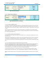
3.1
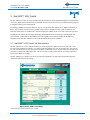
Net-2000™-VCU Control Via Web Interface
The Net-2000™-VCU can be controlled remotely by accessing the unit’s built-in web server using a PC’s web
browser as the graphical user interface. To connect to the Net-2000™-VCU web server home page, first open up
the web browser software on a PC and type the IP address (or hostname if the LAN has a name server) of the VCU
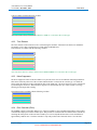
you want to control in the URL address bar. The VCU web server will respond with the VCU Page as shown in
Figure 6 Net-2000™-VCU Page.
The Net-2000™-VCU’s built-in web server provides I/O configuration, system control, information about the
operational mode and network settings.
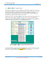
Figure 6 Net-2000™-VCU Page
(values will vary for Net-2000™-VCU version)
Page 9
(Subject to Change)
DVSI CONFIDENTIAL PROPRIETARY
Net-2000™ VCU Users Manual
Version 4.0, December, 2013
Net-2000™ VCU Control
The page is designed to give the operator a operator control and summary of all the settings and parameters of the
Net-2000™-VCU. The page shows the current status of the Net-2000™-VCU, information on what the data rate
and a navigation menu for switching to pages to change system settings. The Vocoder Options table gives the
operator control over features (such as VAD and Echo Cancellor, etc.) that are available to the specific vocoder
implemented. The Voice Source Selection table provides information from the communications channel and
configuration of the vocoder output gain. The operator can control the running of the unit using the Start / Stop
button at the top of the page.
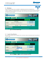
3.2
Navigation Menu
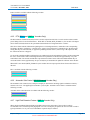
Located across the top under the logo header the navigation menu provides the link to the three main pages used for
setup and control of the Net-2000™-VCU. This menu is visible and assessable from any of the pages. The menu
item is highlighted when the page is displayed.
Figure 7 Navigation Menu
3.2.1
VOIP Mode
Provides selection of I/O, vocoder rate and options, and control of DTMF selection pop up window. The VOIP
Mode window also provides a view of the current setting and system condition.
Figure 8 Example Setup for VOIP Mode
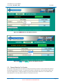
3.2.2
File Mode
Put the Net-2000™-VCU into a ready mode to accept files via Ethernet from a PC. Also allows start and stop of
process.
Page 10
(Subject to Change)
DVSI CONFIDENTIAL PROPRIETARY
Net-2000™ VCU Users Manual
Version 4.0, December, 2013
Net-2000™ VCU Control
Figure 9 Example Setup for File Mode
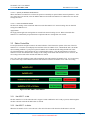
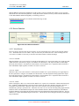
3.2.3
Network Settings Page
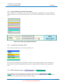
Selecting the System Settings from the navigation menu will display a window with the current network information
of the Net-2000™-VCU. The user can set the Net-2000™-VCU to either obtain the network settings automatically
from a DHCP server (if available) or the user can manually enter the required settings.
Figure 10 Net-2000™-VCU Network Settings Window
3.2.3.1
Obtain IP Automatically Radio Button
When selected the Net-2000™-VCU will get its network settings from the DHCP server on the LAN.
Page 11
(Subject to Change)
DVSI CONFIDENTIAL PROPRIETARY
Net-2000™ VCU Users Manual
Version 4.0, December, 2013
3.2.3.2
Net-2000™ VCU Control
Specify IP Address Radio Button
When selected the Net-2000™-VCU allows the operator to manually set up the Ethernet network parameters. After
new values have been entered, select the APPLY Button to reboot the Net-2000™-VCU and have the new network
settings take effect.
3.2.3.3
Reset to Defaults Button
The Network Settings “Reset to Default” button resets the Net-2000™-VCU network setting value to obtain IP
setting from a DHCP server.
Apply Button
The Apply button applies the settings that are entered in the network settings screen. When selected the Net2000™-VCU automatically stops and reboots to implement the new settings that were entered.
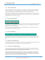
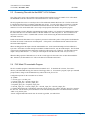
3.3
Status Control Bar
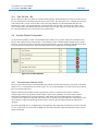
Located just under the navigation menu is the status indication. This informs the operator of the state of the Net2000™-VCU. The status screen displays the host name of the Net-2000™-VCU, what mode the unit is in and the
current running condition. Upon power up the Net-2000™-VCU loads the default settings and the unit is idle.
Click the Start button to begin running the VCU with the default settings. Click the Stop button to put the Net2000™-VCU back into the idle mode. Changes to the settings can be made while the unit is active. However, the
new settings will not take affect until the Start button is clicked.
Note: The “Start New Settings” button will automatically stop and restart the Net-2000™-VCU. It is not necessary
to click on the “Stop” button and then click the Start button to restart the Net-2000™-VCU with a new setting.
Figure 11 Net-2000™ VCU Status
3.3.1
Net-2000™- is Idle
The Net-2000™-VCU is idle when the unit is stopped. In this condition the unit is ready to process data through the
encoder or decoder when the START button is selected.
3.3.2
Net-2000™- is Active
When the Net-2000™-VCU is active the unit is The unit will return to idle when the STOP button is selected.
Page 12
(Subject to Change)
DVSI CONFIDENTIAL PROPRIETARY
Net-2000™ VCU Users Manual
Version 4.0, December, 2013
3.3.3
Net-2000™ VCU Control
Start and Stop Buttons
The Start VOIP Mode button is used to apply all the selected settings on the VOIP page and begin communication
between two Net-2000™-VCUs. The Net-2000™-VCU will remain active in VOIP mode until either the Stop
VOIP mode button is selected or the Start File Mode Button on the File Mode page is selected.
When the Start File Mode Button is selected the Net-2000™-VCU is able to process data via the Ethernet interface.
The Net-2000™-VCU will remain active in file mode until either the Stop file mode button is selected or the Start
VOIP Mode Button on the VOIP page is selected.
3.4
Reset to Defaults Button
A Reset to defaults button is provided to set the I/O and vocoder conditions to the factory default state. Selecting this
reset buttons set the Vocoder Setting Page to the settings that a set on start-up. The Default vocoder values vary
depending on the vocoder implementation.
NOTE: At power-up the VCU automatically starts up with the default settings. You do not need to use the web
interface unless you want to change these settings.
3.5
Version Identification
Selecting the Software Info from the bottom of any page will display a window with the current software version of
the Net-2000™-VCU and the version of the implemented vocoder. There are no user definable settings on this
page.
3.6
Hyperlink to DVSI Web Page
Selecting DVSI’s Web Page from any of the pages will go out of the Local Area Network to the Internet to a DVSI
web page dedicated to Net-2000™ information as well as available manual download.
3.7
VCU Control via Serial Interface
The serial port located on the back of the Net-2000™-VCU unit provides the same control functions as the web
interface. The interface itself consists of a simple command/response ASCII text protocol. To access the interface
use a terminal or terminal emulator on a personal computer to type in commands.
All commands are ASCII character strings terminated by a newline character (ASCII 0x0A). The maximum size
allowed for a command is 512 characters. Commands are case-sensitive. Command arguments are separated by
white space. With the serial cable connected and the terminal running type a few carriage returns at the keyboard.
The Net-2000™-VCU responds with the console prompt as shown below:
Page 13
(Subject to Change)
DVSI CONFIDENTIAL PROPRIETARY
Net-2000™ VCU Users Manual
Version 4.0, December, 2013
Net-2000™ VCU Control
adsh>
Commands to the Net-2000™-VCU can be issued after receiving the prompt. Each time a command is issued to the
Net-2000™-VCU it will respond with a string indicating the command was accepted as “OK” or an error message.
After another prompt is ready to receive a new command. Any newline-terminated string reported by the Net2000™-VCU between the time a command is issued and a new command prompt is received indicates an error was
encountered executing the command.
Commands consist of a command word, zero or more arguments, and a newline (which marks the end of the
command). Commands for the serial port interface are listed in the following subsections.
When issuing commands at the "adsh>" prompt the NET-2000™ VCU will respond with "<cmd> OK" (where
<cmd> is the command issued) or an error message if the command fails.
3.7.1.1
VOIP mode command
The VOIP commands start the Net-2000™-VCU to VOIP mode.
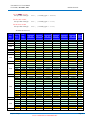
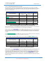
adsh> dut voip <args>
where args are
arg format
-v [h,l,2,2r]
-c [e,a,s]
-o [gain]
-p [port]
-d [config]
arg name
voice source
channel source
codec output
gain
port number
arg values
h=handset, l=4-wire, 2=2-wire, 2r=2-wire wait on ring
e=ethernet, a=RS-422 Asynchronous, s= RS-422 Synchronous
0,-3,-6 dB
for channel source == Ethernet
configuration
data
for VAD, Tone Detection, Noise Suppression, Echo canceller Auto
Gain Control (AGC) and High Pitch Detection (in order) depending
on the vocoder implementation to turn a configuration on use '1' to
turn it off use '0'
For example:
"-d 1 0 0 1 0 0" turns vad ON, echo canceller ON only
-r [vocoder]
vocoder and FEC
vocoder type is "AMBE+2", to specify FEC on or off pass in
",<rate_index>"
For example:
"-r AMBE+2t,01" specifies -1 vocoder with no FEC
[ip_addr]
3.7.1.2
the IP address to
send data to
required only if the channel interface is Ethernet
VOIP Mode Command Example
adsh> dut voip -v l -c e -r AMBE+2,00 192.168.24.173
In this example the Net-2000™-VCU starts VOIP Mode using the 4-wire interface for voice and Ethernet for the
channel using the -1 vocoder with FEC enabled. It communicates with the device at ethernet address
192.168.24.173 with the default UDP port (4000).
Page 14
(Subject to Change)
DVSI CONFIDENTIAL PROPRIETARY
Net-2000™ VCU Users Manual
Version 4.0, December, 2013
3.7.1.3
Net-2000™ VCU Control
FILE mode command:
The File mode command set the Net-2000™-VCU to work in file mode.
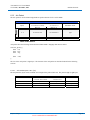
adsh> dut file <args>
where args are
arg format
-p [port]
arg name
port number
-d [config]
configuration
data
arg values
only for channel source == ethernet
for VAD, Tone Detection, Noise Suppression, Echo canceller Auto
Gain Control (AGC) and High Pitch Detection (in order) depending
on the vocoder implementation to turn a configuration on use '1' to
turn it off use '0'
For example:
"-d 1 0 0 1 0 0" turns vad ON, echo canceller ON only
-r [vocoder]
vocoder type ONLY (no need to specify FEC)
vocoder type is "AMBE+2",
vocoder
NOTE: FILE mode implies that both the voice and channel interfaces are Ethernet. Since the rate information is
always in the packet, there is no need to specify the rate index.
3.7.1.4
Stop Command
The Stop command works for either mode and sets the Net-2000™-VCU to IDLE
adsh> dut stop
Change Vocoder Configuration:
adsh> dut config [config]
[config] are the same 1 or 0 values used in the "-d [config]" arg for voip or file mode
3.7.1.5
Send Tones Command
adsh> dut tone [-te or-td] [tone_args]
where args are
"-te" or "-td".
[enc_or_dec]
[tone_args]
3.7.1.6
Either "-te" or "-td". "-te" means override the speech input and
have the encoder send the tones in-band to the other net2k "-td"
means override the input channel data and have the decoder
generate the tones locally.
an ascii string of digits and the upper-case letters [A-F] representing
the DTMF tone to generate
Stop Command
To use the stop command at the adsh> prompt type
dut stop
The Net-2000™-VCU responds with Stop OK and packets information
Page 15
(Subject to Change)
DVSI CONFIDENTIAL PROPRIETARY
Digital Voice Systems, Inc.
Net-2000™ VCU Users Manual
Version 4.0, December, 2013
The Speech Compression Specialists
VOIP Mode
4 VOIP Mode
When the Start VOIP button is selected the unit is active in VOIP mode and ready to communicate
with another Net-2000™ VCU via the Ethernet interface. VOIP mode can also be used for
Loopback communications where it sends data to itself over the internal loopback Ethernet address of 127.0.0.1
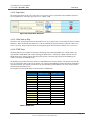
4.1
Net-2000™-VCU VOIP Mode Settings
Figure 12 Net-2000™- VOIP Settings
Page 16
(Subject to Change)
DVSI CONFIDENTIAL PROPRIETARY
Net-2000™ VCU Users Manual
Version 4.0, December, 2013
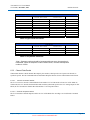
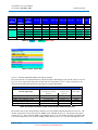
4.2
VOIP Mode
Vocoder Selection (Version Dependant)
The Net-2000™ VCU is available in a variety of vocoder configurations. Depending on the version purchased the
unit may contain one or two of the following vocoders. All versions of the Net-2000™ VCU include A-law and ULaw.
Vocoders
AMBE®
AMBE+™
AMBE+2™
APCO Standard
APCO Enhanced
GMR-1 Vocoder
GMR-2 Vocoder
BGAN Vocoder
GMR-2+ Vocoder
A-Law
U-Law
Figure 13 Vocoder Type and Rate Selection
4.2.1
Forward Error Correction (FEC)
FEC is built into the following version of the Net-2000™ VCU.
Vocoder
AMBE®
AMBE+™
AMBE+2™
APCO Standard
APCO Enhanced
GMR-1 Vocoder
GMR-2+ Vocoder
The vocoder can be selected with or without FEC to allow for various testing conditions. This is a feature that is
ideal for mobile communication applications that experience degraded channel conditions and/or significant bit
errors.
4.3
APCO Vocoder Version – APCO Standard and APCO Enhanced
The Vocoder Type selection window allows the operator to select between the APCO Standard and APCO
Enhanced Vocoders. Only one vocoder can be selected at a time. After switching from one vocoder to the other it
is necessary to select the start button in order to initiate the change.
Page 17
(Subject to Change)
DVSI CONFIDENTIAL PROPRIETARY
Net-2000™ VCU Users Manual
Version 4.0, December, 2013
VOIP Mode
APCO Standard Vocoder Mode
The Full-Rate mode is compatible with the current APCO P25 standard. The P25 standard vocoder has a total data
bit rate of 7200 bps. Of these bits 4400 bps is voice data and 2800 bps is Forward Error Correction (FEC). The
vocoder can be selected with or without FEC.
Figure 14 APCO Standard Vocoder Selection
The APCO Enhanced Vocoder is DVSI’s new vocoder technology. The APCO Enhanced vocoder in the Net2000™- P25 VCU offers the flexibility of data rate, FEC and Bit stealing selection. of 3600 bps. This new vocoder
is designed to be particularly robust and perform exceptionally well even under the presence of bit errors and
acoustic background noise conditions.
Figure 15 APCO Enhanced Vocoder Selection
4.3.1
APCO Enhanced Vocoder Bit Stealing
The APCO Enhanced vocoder offer the ability to steal up to six bits from the vocoder. This mode can be used to
transmit user data in-band.
4.3.2
APCO Enhanced Vocoder Additional Features
As part of Half-Rate vocoder mode the Net-2000™ VCU offers the ability to decode up to 8 bits of Soft Decision
Forward Error Correction. This feature is ideal for testing and evaluating degraded channel conditions and/or
significant bit errors.
In addition to the enhanced FEC capability the Net-2000™ VCU Half-Rate vocoder provides voice activity
detection and DTMF Knox Tone detection and regeneration. See Section 4 Protocol for more information.
Page 18
(Subject to Change)
DVSI CONFIDENTIAL PROPRIETARY
Net-2000™ VCU Users Manual
Version 4.0, December, 2013
4.4
VOIP Mode
AMBE® / AMBE+™ Vocoders Version
The AMBE® mode is compatible with DVSI’s AMBE-1000™, AMBE-2000™ and AMBE-2020™ Vocoder Chips.
DVSI’s proprietary AMBE® Voice Compression Technology delivers excellent voice quality even at low data rates.
Proven to be a superior alternative to linear predictive model vocoders, the AMBE® Voice Compression
Technology has been chosen as the standard for several major satellite and mobile radio communications systems.
The Net-2000™ VCU supports AMBE® Vocoder bit rates from 2000 to 9600 bps. The rates available are the
combination of the speech data and the Forward Error Correction (FEC).
Independent test results have shows DVSI’s AMBE+™ Vocoder running at 4.8 kbps and 4.0 kbps outperforms both
the ITU G.726A vocoder at 32 kbps and the ITU G.729 vocoder at 8 kbps. This voice coder builds upon the
strengths of DVSI’s previous IMBE™ and AMBE® Technology to provide toll quality speech with unsurpassed
robustness to both acoustic noise and channel errors. The AMBE+™ Vocoder provides a 2-8 times reduction in bit
rate while delivering toll-quality performance with maximizing bandwidth efficiency.
Figure 16 AMBE® / AMBE+™ Vocoder Type and Rate Selection
Vocoder Type and rate/FEC selection is done from the VOIP Mode window. To set the Net-2000™ VCU vocoder,
first select the vocoder mode (AMBE® / AMBE+™ or AMBE+2™), then select the Rate / FEC using the Bit Rate
drop down menu. The default vocoder is set to AMBE+2™ @ 4000 bps with 0 bps FEC.
Page 19
(Subject to Change)
DVSI CONFIDENTIAL PROPRIETARY
Net-2000™ VCU Users Manual
Version 4.0, December, 2013
4.5
VOIP Mode
AMBE+2™ Vocoder Version
The AMBE+2™ Vocoder is DVSI’s newest low data rate vocoder technology. The Net-2000™ VCU incorporates
the AMBE+2™ Vocoder at 4.0 kbps with no FEC. It has been shown to outperform DVSI’s previously industryleading AMBE+™ Vocoder and AMBE™ vocoder technologies. It is designed to be particularly robust and
perform exceptionally well even under bit errors and acoustic background noise conditions.
Table 5 AMBE+2™ Vocoder Data Rate Selection
4.6
Vocoder Selection (GMR-1 or GMR-2 Version)
Vocoder Type and rate/FEC selection is done from the VOIP Mode window. The user has the ability to run the
GMR-1 or GMR-2 (depending on the Net-2000 version) vocoder with or without FEC using the Data Rate drop
down menu. The default rate for the GMR-1 vocoder is 5200 bps (4000 bps speech source with 1200 bps FEC).
The only rate for the GMR-2 vocoder is 3600 bps (3600 bps speech source with 0 bps FEC).
4.6.1
GMR-1 Vocoder Selection
Figure 17 GMR-1 Vocoder Selection
Page 20
(Subject to Change)
DVSI CONFIDENTIAL PROPRIETARY
Net-2000™ VCU Users Manual
Version 4.0, December, 2013
4.6.2
VOIP Mode
GMR-2 Vocoder Selection
Figure 18 GMR-2 Vocoder Selection
4.7
BGAN Vocoder Selection
The VCU contains an implementation of Inmarsat’s BGAN 4 kbps vocoder. Vocoder Type selection is done from
the VOIP Mode Vocoder window. The only BGAN vocoder data rate option user has the ability to run is 4000 bps
with no FEC. This is the default and only selection in the drop down menu.
Figure 19 BGAN Vocoder Selection
4.8
GMR-2+ Vocoder Selection
To run the GMR-2+ vocoder , select it from the Vocoder Type drop down. The user has the ability to run GMR-2+
vocoder with or without FEC using the Data Rate drop down menu. The default rate for the GMR-2+ vocoder is
6000 bps (2450 bps speech source with 3550 bps FEC). Other rates available for the GMR-2+ vocoder are as
follows: 2450 bps speech with 0 bps FEC; Bit Steal one bit - 2450 bps speech source with 3550 bps FEC; Bit Steal
one bit - 2450 bps speech with 0 bps FEC.
Figure 20 GMR-2+ Vocoder Selection
Page 21
(Subject to Change)
DVSI CONFIDENTIAL PROPRIETARY
Net-2000™ VCU Users Manual
Version 4.0, December, 2013
4.8.1
VOIP Mode
Rate “Bit Steal 1 Bit”
The two “Bit Steal 1 Bit” rates allow for customized data signaling. When running in one of these rates the value of
the least significant bit of the data bits has no effect on the vocoder. The “Bit Steal one bit - 2450 bps speech source
with 3550 bps FEC” rate has 72 bits of data, so the value of the LSB (bit 71 of the channel data bits) does not
influence the vocoder. The “Bit Steal one bit - 2450 bps speech with 0 bps FEC” rate has 49 bits of data, so the
value of LSB (bit 48 of the channel data bits) has no effect on the vocoder. Since the vocoder does not care about
the value of this data bit, users can steal this bit for customized use.
4.9
Vocoder Options Configuration
To fine tune the capability of either vocoder mode the NET-2000™-VCU provides VAD, Echo cancellation Tone
Detector and Automatic Gain Control options. The availability of these extended features depends on the vocoder
selection. To turn ON an option use the home page navigation menu to get to the VOIP Page and click on the check
box for the desired vocoder option. Then click on the Start button to enable the new setting selection.
Figure 21 Vocoder Options
4.9.1
Voice Activation Detection (VAD)
The Voice Activation Detection (VAD) algorithm along with the Comfort Noise Insertion (CNI) feature of the NET2000™-VCU is a useful function for systems trying to save in system bandwidth or to reduce transmit power during
times of conversational silence.
With the VAD functions enabled, periods of speech silence will be recognized by the encoder. Instead of
compressing the silence as speech the encoder outputs a silence frame (in-band). This silence frame contains
information regarding the level of background noise, which allows the corresponding decoder to synthesize a
“Comfort Noise” signal at the other end. The comfort noise is intended to give the listener the feeling that the call is
still connected, as opposed to producing absolute silence, which can give the impression that, the call has been
“dropped”.
The silence threshold value is -25 dBm0 in the VAD algorithm. Each frame that exceeds this level will be classified
as voice. If the frame level is less than -25 dBm0 the voice/silence decision will be determined based upon various
adaptive thresholds.
Page 22
(Subject to Change)
DVSI CONFIDENTIAL PROPRIETARY
Net-2000™ VCU Users Manual
Version 4.0, December, 2013
VOIP Mode
VAD is available with the following vocoders:
Vocoder
AMBE®
AMBE+™
AMBE+2™
APCO Enhanced
GMR-1
GMR-2
BGAN Vocoder (Always ON)
GMR-2+ Vocoder (Always ON)
Note: The VAD is always enabled when BGAN or GMR-2+ is selected as the vocoder type.
4.9.2
Tone Detector
The Tone detector can be turned on or off is selected using the checkbox. When the Tone detector in enabled the
Net-2000™ VCU is able to send and receive North American DTMF tones.
Tone Detection is available with the following vocoders:
Vocoder
AMBE® (Always ON)
AMBE+™ (Always ON)
AMBE+2™
APCO Enhanced
GMR-1
GMR-2
BGAN Vocoder
GMR-2+ Vocoder
Note: The Tone detector is always enabled when AMBE®/AMBE+™ is selected as the vocoder type.
4.9.3
Noise Suppressor
The Noise suppressor feature of the Net-2000™ VCU provides clear voice in environments with background noise.
This feature work only when one of the vocoders indicated below is selected as the vocoder type. To enable the
feature select the check box in the Configuration table on the VOIP page. The noise suppressor can be switched off
by unchecking the check-box. When the noise suppressor is started it may take up to a few seconds to converge
allowing for it do begin fully working.
Noise Suppression is available with the following vocoders:
Vocoder
AMBE+2™
APCO Enhanced
BGAN Vocoder
GMR-2+ Vocoder
4.9.4
Echo Canceller (Echo)
The AMBE® software on the NET-2000™-VCU employs an adaptive echo cancellation algorithm to cancel echoes
of the decoder output present at the encoder input. This provides a 16-millisecond echo canceller that is suitable for
canceling the linear portion of the local echo caused by a 2-to-4 wire hybrid and can achieve echo cancellation of
approximately 30dB or more. The Echo canceller is only really useful when connected via the 2-wire interface.
Page 23
(Subject to Change)
DVSI CONFIDENTIAL PROPRIETARY
Net-2000™ VCU Users Manual
Version 4.0, December, 2013
VOIP Mode
Echo Canceller is available with the following vocoders:
Vocoder
AMBE®
AMBE+™
AMBE+2™
APCO Enhanced
GMR-1
GMR-2
BGAN Vocoder
GMR-2+ Vocoder
4.9.5
DTX (BGAN and GMR-2+ Vocoders Only)
The Discontinuous Transmission (DTx) feature is used in conjuction with VAD. It can be used to reduce transmit
power during times of conversational silence. When DTx is checked (DTX_ENABLE=1), the encoder will output a
silence frame (in-band) whenever the speech data is determined to be background noise or silence.
This silence frame contains information regarding the level of background noise, which allows the corresponding
Net-2000’s decoder to synthesize a “Comfort Noise” signal. The comfort noise is intended to give the listener the
feeling that they are still connected, as opposed to producing absolute silence, which can give the impression that,
the connection has been “dropped”.
To ensure the smoothest audible transitions between synthesized speech and synthesized silence, DVSI recommends
the user to send a silence frame with background noise level parameters to the decoder approximately every 5001000 milliseconds. The encoder and decoder expects that most silence frames will be discarded and that only an
occasional silence frame (approximately one per second) may be transmitted to update the CNI state at the decoder.
When DTX is not checked (DTX_ENABLE=0), the encoder does not output special silence frames when silence is
detected.
DTx is available with the following vocoders:
Vocoder
BGAN Vocoder
GMR-2+ Vocoder
4.9.6
Automatic Gain Control (APCO Enhanced Vocoder Only)
The Automatic Gain Control (AGC) attempts to amplify or attenuate the incoming signal to maintain a relatively
constant voice level. The applied gain is limited to [+20,-10] dB. Automatic Gain Control is available with the
following vocoders:
Automatic Gain Control detection is available with the following vocoder:
Vocoder
APCO Enhanced
4.9.7
High Pitch Detection Feature (GMR-2+ Vocoder Only)
When checked (enabled) High Pitch Detection (HPD) increases the pitch range of the vocoder in order to
accommodate voices with an especially high pitch voice. The vast majority of speakers do not exceed the vocoder’s
typical pitch limits. In very rare cases when HPD is required it may be enabled.
Page 24
(Subject to Change)
DVSI CONFIDENTIAL PROPRIETARY
Net-2000™ VCU Users Manual
Version 4.0, December, 2013
VOIP Mode
With the HPD not checked (not enabled) the vocoder creates a period of constant pitch when it receives any pitch
fluctuations above the maximum pitch limit. During this time the decoded voice may sound somewhat different but
is still understandable and the intelligibility is reasonably preserved.
The High Pitch detection feature is available with the following vocoder:
Vocoder
GMR-2+ Vocoder
4.10 Source Selection
Figure 22 Voice Source Selection
4.10.1 Voice Source
The Voice Source menu provides the user the choice to select which input source will be used on the Net-2000™VCU. The default source is set to 4-Wire. Only one source may be selected at a time. After switching from one
voice source to another it is necessary to select the start button in order to initiate the change.
4.10.1.1 Handset
When the Handset voice source interface is selected, the Net-2000™-VCU expects the analog voice signal input and
output on the RJ11 jack (Item 8 in Figure 1 Net-2000™-VCU Rear Panel). The output will also be on the output
RCA jack (Item 6 Figure 1 Net-2000™-VCU Rear Panel). The Net-2000™-VCU outputs the audio to both the 4Wire and Handset output regardless of which voice source is selected.
4.10.1.2 4-Wire
When the 4-Wire voice source interface is selected, the Net-2000™-VCU expects the analog voice signal input on
the RCA jack (Item 7 in Figure 1 Net-2000™-VCU Rear Panel). The unit outputs the analog signal on the output
RCA jack (Item 6 Figure 1 Net-2000™-VCU Rear Panel). The Net-2000™-VCU outputs the audio to both the 4Wire and Handset output regardless of which voice source is selected.
4.10.1.3 2-Wire
Before selecting the 2-Wire voice source the Net-2000™-VCU expects to be connected to a North American POTS
line. A industry standard telephone cord can be used to connect the wall jack to the RJ11 jack (Item 5 in Figure 1
Net-2000™-VCU Rear Panel). When the 2-Wire voice source interface is selected, the Net-2000™-VCU
automatically “picks-up” (opens) the line. When the voice source set to 2-wire the incoming analog signal from the
POTS line will be encoded and then output to the selected channel interface (RS-422 or Ethernet). If the Ethernet
loopback channel is selected then the encoded speech will be decoded and sent out through the POTS line. The Net2000™-VCU 4-Wire and Handset outputs are not active. The POTS line can be hung-up (released) by selecting the
Stop VOIP button.
Page 25
(Subject to Change)
DVSI CONFIDENTIAL PROPRIETARY
Net-2000™ VCU Users Manual
Version 4.0, December, 2013
VOIP Mode
4.10.2 Output Gain
The output gain setting for the voice codec can be set by the user, however, the default values should be sufficient
for most applications. The Output gain can be set to -3dB or -6 dB.
Figure 23 Output Gain Selection
4.10.3 2-Wire Wait on Ring
The 2-Wire wait on ring feature allows the Net-2000™-VCU to be ready to answer an incoming call from a standard
POTS line. When selected the Net-2000™-VCU will not automatically open the POTS line when the 2-Wire voice
source is selected. This provides the benefit of freeing up the phone line when the Net-2000™-VCU is not active.
4.10.4 DTMF Panel
The NET-2000™-VCU is capable of detecting, transmitting, and synthesizing DTMF tones. DTMF features are
only enabled in VOIP Mode with vocoders that support DTMF Tones. Selecting the “OPEN” button next to the
DTMF Panel on the main navigation menu brings the operator to the Status page and opens the DTMF pop-up
window (see Figure 24 DTMF Key Pad).
The DTMF pop-up window allows the operator to send DTMF tones across the channel. The operator can enter the
tones by selecting the digits in the pop-up window or by selecting the DTMF digit window and entering the numbers
using the keyboard. The operator can select how the tone should be generated and then can select send to send the
information the Net-2000™-VCU.
The frequencies for the DTMF tones are shown in Table 6 DTMF Data
DTMF
Frequency 1 (Hz)
1336
1209
1336
1477
1209
1336
1477
1209
1336
1477
1633
1633
1633
1633
1209
1477
Digit
0
1
2
3
4
5
6
7
8
9
A
B
C
D
*
#
DTMF
Frequency 2 (Hz)
941
697
697
697
770
770
770
852
852
852
697
770
852
941
941
941
Table 6 DTMF Data
Page 26
(Subject to Change)
DVSI CONFIDENTIAL PROPRIETARY
Net-2000™ VCU Users Manual
Version 4.0, December, 2013
VOIP Mode
*Note: Dial, ring, and busy tones are standard North American call progress tones.
Figure 24 DTMF Key Pad
4.10.4.1 Send Button
The Send button sends the digits entered in the DTMF digit window out to the select device (encoder or decoder)
4.10.4.2 Clear Button
The Clear button allows the operator to delete all the digits entered in the DTMF digit window.
4.10.4.3 BK SP Button
The BK SP button allows the operator to delete the last digit entry from the DTMF digit window.
Encoder Radio Button
When the Send button is selected and the Encoder radio button is active then the digits in the DTMF window are
sent from the encoder across the channel. A the other side of the channel the information is decoded. The encoder
and decoder radio button can not be active at the same time. The encoder passes the DTMF data in-band (within the
regular voice data bits) so that normal DTMF tones pass seamlessly from the encoder to the decoder. The decoder
synthesizes a DTMF tone in response to reception of an in-band DTMF tone data in the frame.
4.10.4.4 Decoder Radio Button
When the send button is selected and the Decoder radio button is active then the Net-2000™-VCU sends tone
directly to the local decoder to output the digits as entered in the DTMF digit window. The decoder and encoder
radio button can not be active at the same time.
Close
Selecting the Close button closes the DTMF pop-up window.
4.11 Channel Settings
The Net-2000 can be configures to encode / decode speech from one of three communications channel sources. The
default channel is Ethernet loopback. Only one communication mode may be selected at a time. After switching
from one communication mode to another it is necessary to select the start button in order to initiate the change.
Page 27
(Subject to Change)
DVSI CONFIDENTIAL PROPRIETARY
Net-2000™ VCU Users Manual
Version 4.0, December, 2013
VOIP Mode
Figure 25 Channel Source
4.11.1 Channel Source Selection
Figure 26 Channel Source Selections
4.11.1.1 Ethernet Loopback (Local)
In loopback communications mode the Net-2000™-VCU will encode speech received on the selected voice source
input (Handset 4-Wire or 2-Wire) and play out the encoded/decoded speech on the handset and Line-Out interface.
This channel selection is useful when encoding / decoding recorded voice samples as a quick analysis of the selected
vocoder.
When Loopback communications mode is selected the Net-2000™-VCU sends data over the internal loopback
Ethernet address of 127.0.0.1 Loopback can also be accessed by entering in the IP or host name of the Net-2000™VCU in the Target IP address box.
4.11.1.2 Ethernet Channel Source Interfaces
Selecting Ethernet as the Channel source allows the Net-2000™-VCU to communicate to another device across an
Ethernet network.
When running in VOIP Mode the VCU encodes a frame of speech from the specified voice interface and sends the
encoded data over the Ethernet channel interface to the target IP address. At the same time the VCU expects to
receive packets from the Ethernet communications channel interface that contains a decode command and encoded
data.
4.11.1.3 RS-422 Asynchronous and RS-422 Synchronous Interfaces
When either of the RS-422 interfaces are selected the Net-2000™-VCU encodes speech received on the selected
voice source input (Handset 4-Wire or 2-Wire) sends out the encoded speech data over the selected RS-422
interface. This channel selection is useful when encoding / decoding voice between two Net-2000™-VCU that are
not located far apart. Two Net-2000™-VCU units can be easily connected together using the Asynchronous
connection and a crossover CAT5 cable. See Section 5 for connector pinout details.
In VOIP mode the Net-2000™-VCU also transmits packets over the asynchronous RS-422 interface when the
Ethernet interface is the channel source. This is a useful method to monitor the Net-2000™-VCU channel data.
NOTE: DO NOT attempt to connect or use the RS-422 Asynchronous and RS-422 Synchronous ports at the same
time.
Page 28
(Subject to Change)
DVSI CONFIDENTIAL PROPRIETARY
Net-2000™ VCU Users Manual
Version 4.0, December, 2013
VOIP Mode
4.11.2 Target IP Address
The Net-2000™-VCU can communication with another NET-2000™. To communicate (encode and decode to /
from) to another Net-2000™-VCU via Ethernet first select Ethernet as the Channel source. Next enter the IP
address or host name of the remote unit you are connecting to, in the Target IP address box located under the
Channel source pull down menu.
4.11.3 Port Number
The network settings page allows the operator to change the network port number for the communication channel.
The default port number is Port 4000. If a different port number is required enter in the desired port number and
select the configure button. Valid port numbers are greater than 1024 and less than 65535. Port numbers 4001,
4002 and 4003 are reserved by the Net-2000™-VCU and must not be used.
Page 29
(Subject to Change)
DVSI CONFIDENTIAL PROPRIETARY
Digital Voice Systems, Inc.
Net-2000™ VCU Users Manual
Version 4.0, December, 2013
The Speech Compression Specialists
File Mode
5 File Mode
In File mode the Net-2000™-VCU is available for communication with a PC on an Ethernet LAN
in order to send data to be encoded or decoded. To set the Net-2000™-VCU to be in file I/O mode select File Mode
from the top menu of the Net-2000™-VCU home page. Once selected select the start button and the Net-2000™VCU will be ready in File Mode.
Figure 27 File Mode Web Page
5.1
Vocoder Type Selection
The vocoder type selection sets the Net-2000™-VCU to be ready to encode or decode packets that correspond to the
selected vocoder.
Figure 28 AMBE® / AMBE+™ Version File Mode Selection
Page 30
(Subject to Change)
DVSI CONFIDENTIAL PROPRIETARY
Net-2000™ VCU Users Manual
Version 4.0, December, 2013
File Mode
Figure 29 APCO Version File Mode Selection
Figure 30 GMR-1 Version File Mode Selection
Page 31
(Subject to Change)
DVSI CONFIDENTIAL PROPRIETARY
Net-2000™ VCU Users Manual
Version 4.0, December, 2013
File Mode
Figure 31 GMR-2 Version File Mode Selection
Figure 32 BGAN and GMR-2+ Version File Mode Selection
5.2
Channel Selection Port Number
The network settings page allows the operator to change the network port number for the communication channel.
The default port number is Port 4000. If a different port number is required enter in the desired port number and
select the configure button. Valid port numbers are greater than 1024 and less than 65535. Port numbers 4001,
4002 and 4003 are reserved by the Net-2000™-VCU and must not be used.
Page 32
(Subject to Change)
DVSI CONFIDENTIAL PROPRIETARY
Net-2000™ VCU Users Manual
Version 4.0, December, 2013
5.3
File Mode
Processing Files with the Net-2000™-VCU Software
Note: There is PC source code provided on the included CD that interfaces to the Net-2000™-VCU in File Mode.
The README on the disc describe how to build and run the PC software example.
The PC program allows users to encode speech to a file and decode channel data from a file. The file mode works
in conjunction with software provided by DVSI that runs on a PC. To work in file mode you first have to load the
PC software onto a PC connected to an Ethernet network that has access to the Net-2000™-VCU. Set the Net2000™-VCU to file mode and the unit is now ready to accept packets from the PC using the PC program.
The PC program can run in Windows command prompt (DOS) window. It is comprised of commands that contain
the name of the file to be run and the address of the Net-2000™-VCU that will process it. The Net-2000™-VCU
can process one file at a time. Customized PC software can be written using the Protocol information that is
described in section 4.
In this mode when the Net-2000 receives a packet it processes it and returns a packet. If the packet is PCM data the
Net-2000 will encode it and return an encoded packet. . If the packet is encoded data the Net-2000 will decode it
and return and PCM packet.
When encoding packets the input to the Net-2000 should be raw 16-bit linear PCM samples in little-endian (PC)
byte-order. No headers or format descriptions should be included in the file, only the 8 kHz samples. The Net-2000
will return an encoded packet that contains the vocoder bits with one byte per vocoder bit. The Net-2000 encoder
output is always hard-decision -- i.e., each byte in the output file will either take the value zero (0) or one (1).
When decoding a packet of data make sure to set the vocoder type to be the same as the vocoder that encoded the
data. Otherwise, the Net-2000™-VCU will see the data as invalid and return silence.
5.4
FILE Mode PC-executable Program
The PC executable program is included with the Net-2000™-VCU. To install the PC software, first create a
directory called Net2000 and copy the contents of the floppy disk to it. To run the PC program, open up a command
prompt window, change to the Net2000 directory and run the net2k_file.exe file.
Configuration options for the executable are as follows:
-ip <ipaddr>
-r <vocoder_type><vocoder_rate>
-e <encoder_input_file> <encoder_output_file>
-d <decoder_input_file> <decoder_output_file>
-l <loopback_input_file> <loopback_output_file>
-f <encoder_input_file> <encoder_output_file> <decoder_input_file> <decoder_output_file>
****NOTE: When using the -f (full-duplex option the encoder_output_file> and the <decoder_input_file> cannot be
the same file. The file will be processed and save to the same directory that the PC executable software is located.
-sdbits <soft_decision_bits>
-cmode <4 digit hexadecimal cmode value for encoder (eg 0xf0a1 ) See table below
Page 33
(Subject to Change)
DVSI CONFIDENTIAL PROPRIETARY
Net-2000™ VCU Users Manual
Version 4.0, December, 2013
NS_ENABLE
0x0040
AGC_ENABLE
0x2000
HPD_ENABLE
0x0200 (GMR-2+ )
DTX_ENABLE
0x0800
0x1000
ON
-25
ON
N/A
N/A
N/A
N/A
0x1040
0x0000
0x1040
0x1040
0x1040
0x1040
0x1240
ON
N/A
ON
ON
ON
ON
ON
-25
0
0
-20
-25
-20
0
ON
N/A
ON
ON
ON
ON
ON
ON
N/A
ON
N/A
N/A
ON
ON
N/A
N/A
OFF
N/A
N/A
N/A
OFF
N/A
N/A
N/A
N/A
N/A
N/A
ON
N/A
N/A
N/A
N/A
N/A
OFF
OFF
AMBE®
AMBE+™
AMBE+2™
APCO Standard
APCO Enhanced
GMR-1 Vocoder
GMR-2 Vocoder
BGAN Vocoder
GMR-2+ Vocoder
VAD_ENABLE
Default
cmode
Values
Vocoders
VAD_LEVEL
TONE_DET_ENABLE
0x1000
File Mode
Table 7 cmode default values
To select more than one vocoder option at a time you must AND the desired ON /OFF values
The VAD level is set at the recommended value and should typically not be changed.
5.4.1
EXAMPLE (encode):
To encode a file of 16-bit PCM 8kHz voice samples to bits use the following command (on a single line):
net2k_file -ip <net2k_ip_addr> -r <vocoder_type>,<index_no> -e <input_file> <output_file>
where
<net2k_ip_addr> is the IP address of the net2k
(DEPENDING ON WHICH VOCODER IS IMPLEMENTED IN THE NET-2000)
<vocoder_type> is either one of the following
"ambe+2t,00" for GMR-1 at 4000 bps source 1200 bps FEC
or "ambe+2t,01" for GMR-1 at 4000 bps source 0 bps FEC
or "ambemm,01" for GMR-2 at 3600 bps source 0 bps FEC
or "ambe2000,<index_no>" where 0 <= <index_no> < 32 for AMBE-2000 compatible Rates
or "ambe+2,<index_no>" where 48 <= <index_no> < 64 for AMBE+2 rates
or "ambe+2a,<index_no>" where 0 <= <index_no> <= 3 for APCO Enhanced rates
or "ambe+2i,0" for BGAN rate of 4000 bps / 0 bps FEC
or "ambe+2g,<index_no>" for GMR-2+ where <index_no> sets the following rates
<index_no> = 0 for 6000 bps (2450 bps src / 3550 bps FEC)
<index_no> = 1 for 2450 bps (2450 bps src / 0 bps FEC)
<index_no> = 2 for Bit Steal 1 Bit (2450 bps src / 3550 bps FEC)
<index_no> = 6 for Bit Steal 1 Bit (2450 bps src / 0 bps FEC)
or "apco,0" for Standard APCO rate at 4400 bps source and 2800 bps FEC
or "apco,1" for Standard APCO rate at 4400 bps source and 0 bps FEC
or "u-law"
or "a-law"
Page 34
(Subject to Change)
DVSI CONFIDENTIAL PROPRIETARY
Net-2000™ VCU Users Manual
Version 4.0, December, 2013
File Mode
<input_file> is the file containing the 16-bit linear PCM
<output_file> is the file to write channel bits to
NOTE:
The Net-2000 MUST be running in File mode before executing this program.
The input files when encoding should be raw 16-bit linear PCM samples in little-endian (PC) byte-order. No
headers or format descriptions should be included in the file, only the 8kHz samples. The output files contain the
vocoder bits with one byte per vocoder bit. The net2k encoder output is always hard-decision -- i.e., each byte in the
output file will either take the value zero (0) or one (1). For the mu-law and A-law encoder the output is 8-bit mulaw or A-law samples with one byte per sample.
5.4.2
EXAMPLE (decode):
To decode an encoder output file into synthesized speech use the following command:
net2k_file -ip <net2k_ip_addr> -r <vocoder_type>,<index_no.> -sdbits <n_sdbits> -d <input_file> <output_file>
where
<net2k_ip_addr> is the IP address of the net2k
<vocoder_type> SEE ABOVE LIST
Soft Decision ONLY applies to the AMBE+™, AMBE+2™ , GMR-1 and GMR-2+ Vocoders
<n_sdbits> are the number of soft-decision bits per channel bit (1-4)
<input_file> is the input file for the decoder
<output_file> is the output file for the decoder
Input files should contain one channel bit per byte scaled to the desired number of soft-decision bits. For example,
if one soft-decision bit is used each byte should take the value zero (0) or one (1). If eight soft decision bits are
used, the most confident zero is zero (0x00) and the most confident one is 255 (0xff). Output files are in raw 16-bit
linear pcm with no headers or format descriptions. For the mu-law and A-law decoders the channel data is assumed
to contain one mu-law or A-law sample in each byte.
Page 35
(Subject to Change)
DVSI CONFIDENTIAL PROPRIETARY
Digital Voice Systems, Inc.
Net-2000™ VCU Users Manual
Version 4.0, December, 2013
The Speech Compression Specialists
Interface Protocol
6 Interface Protocol
The VCU implements a channel data interface using a special protocol designed by DVSI. The Net-2000™-VCU
VCU packet is described from the point-of view of the Net-2000™-VCU.
6.1
Serial Port Protocol
The RS-422 interface protocol is exactly the same as the Ethernet protocol interface but, with an extra 16-bit sync
word so that sync up can done in the middle of a transmission.
6.2
Ethernet Protocol
The Net-2000™-VCU uses port 4000 for communication of channel and voice data across the Ethernet interface.
Port 4000 -- the Net-2000™-VCU sends channel/voice data over this port when the channel/voice interface is
Ethernet. It also uses this port for vocoder commands. The default port number is 4000, but a different port number
can be assigned by using the web interface control and selecting the Net-2000™-VCU settings button.
Note: Port numbers 4001, 4002 and 4003 are reserved by the Net-2000™-VCU and
must not be used. Valid port numbers are greater than 1024 and less than 65535.
6.3
Packet Protocol Description
The Ethernet protocol of the Net-2000™-VCU’s uses port 4000. Byte order for all 16-bit data types (“short” in the
C-language data structure) is network order (big endian), so bytes with lower indexes are the most significant. Since
PC’s are little endian machines it is necessary to byte-swap when using this protocol with a PC.
The VCU utilizes two categories of packets: Command Packets and Response Packets. Command Packets are
received by a VCU from another VCU in VOIP mode or from a connected PC in File Mode. Command Packets
direct a VCU to perform a specific action such as decoding or encoding voice data or performing a reset operation.
Response Packets are generated by a VCU and are either the result of a vocoder operation, a reset operation or an
unrecognized received packet. Command and Response Packets have five different formats:
Channel Data Packets
Contains channel data output by the VCU encoder (coded speech) or input to the VCU decoder to synthesize speech.
Decode Command Packets and Channel Response Packets use the Channel Data Packet format.
Voice Data Packets
Contains 8kHz sample rate 16 bit PCM voice data that are inputs to the VCU encoder or are synthesized outputs of
the VCU decoder. Encode Command Packets and Voice Response Packets use the Voice Data Packet format.
Reset Packets
Reset Packets are used in File Mode to initialize the encoder and/or decoder.
Ack Packets
Ack Packets are used in File Mode to confirm that a Reset Packet was executed successfully.
Nack Packets
Nack Packets are transmitted by the VCU in response to an invalid received packet.
Page 36
(Subject to Change)
DVSI CONFIDENTIAL PROPRIETARY
Net-2000™ VCU Users Manual
Version 4.0, December, 2013
Interface Protocol
When the VCU is in VOIP Mode it exchanges Decode Command Packets with another VCU in real time to provide
a full duplex communication channel. The encoder in a VCU compresses speech from its analog handset and 4-wire
sources and transmits it to a receiving VCU using Decode Command Packets. The decoder in the VCU synthesizes
the channel data from a received Decode Command Packet into speech and sends it to its analog interfaces.
When the VCU is in File Mode, it monitors port 4000 (or a different port if one has been selected using the web
interface) for incoming packets. If a Reset packet is received the VCU resets the encoder and/or decoder as
specified in the packet and responds to the packet sender with an ACK packet. If an Encode Command Packet is
received the VCU encodes the voice data in the packet and responds to the sender with a Channel Response Packet
containing the encoded data. If a Decode Command Packet is received, the VCU decodes the channel data in the
packet and responds to the sender with a Voice Response Packet containing synthesized speech. In File Mode it is
possible to produce bit-exact, repeatable results for vocoder quality testing.
PC source code is provided on the CD included with the VCU that implements the protocol and can be used with the
VCU in File Mode to encode and decode speech.
6.3.1
Packet Header
Every packet in the protocol starts with a six-byte header containing a 16-bit integer indicating the overall length of
the packet in bytes, a 16-bit integer indicating the type of the packet, and a 16-bit sequence number. The six-byte
packet header for all data packets is shown in Table 8. An “x” is used in all the tables in this description to indicate
that a bit can take a value of 0 or 1.
Packet Header
Header
Bytes
(msb-lsb)
16 bit Word
15 14 13 12 11 10 9 8
Byte (n)
6543210
Byte (n+1)
Parameter Name
0–1
00000000
xxxxxxxx
len
2–3
00000000
xxxxxxxx
type
4–5
xxxxxxxx
xxxxxxxx
seq
Table 8 Packet Header
Bytes 0 and 1 hold the 16-bit length of the packet (see Table 9 len Header ). Maximum packet length is 514 bytes.
Bytes 2 and 3 hold the 16-bit packet type (see Table 10 type ). Bytes 4 and 5 hold the 16-bit sequence number
parameter (see Table 11 seq Header .) The sequence number of a response to a command packet is the command
packet sequence number plus one. The sequence number is used as a method to detect that no data packets are
dropped, so it is important to ensure that consecutive sequence numbers are transmitted for voice and channel data
packets during operation.
len = Length (in bytes) of total packet (including header)
16 bit Word
15 14 13 12 11 10 9 8
76543210
Byte 0
Byte 1
Minimum Value
00000000
00000110
Maximum Value
00000010
00000000
Decimal Value
6 bytes
514 bytes
Table 9 len Header Parameter
Page 37
(Subject to Change)
DVSI CONFIDENTIAL PROPRIETARY
Net-2000™ VCU Users Manual
Version 4.0, December, 2013
Interface Protocol
type = Packet type
16 bit Word
15 14 13 12 11 10 9 8
Byte 2
00000000
00000000
00000000
Command Packets
Reset
Encode
Decode
Byte 2
00000000
00000000
00000000
00000000
Response Packets
ACK
NACK
Voice
Channel
76543210
Byte 3
00000000
00000010
00000011
Decimal Value
0
2
3
Byte 3
00000000
00000001
00000010
00000011
Decimal Value
0
1
2
3
76543210
Byte 5
00000000
00000000
11111111
Decimal Value
-32768
0
32767
Table 10 type Header Parameter
seq = Sequence number*
16 bit Word
15 14 13 12 11 10 9 8
Byte 4
10000000
00000000
01111111
Minimum Value
Reset Start Value
Maximum Value
Table 11 seq Header Parameter
*Note: Sequence numbers should be incremented by one every time a packet is
transmitted. When the sequence number reaches 32767, the next valid sequence
number is -32768.
6.3.2
Channel Data Packet
Channel Data Packets contain channel data output by the encoder (coded speech) or are inputs to the decoder to
synthesize speech. Decode Command Packets and Channel Response Packets use the Channel Data Packet format.
6.3.2.1
Decode Command Packet
The VCU can receive Decode Command Packet from another VCU in VOIP mode or from a PC in File Mode. In
VOIP mode, the VCU decodes the channel data and sends the synthesized speech to the VCU analog outputs. In File
Mode, the VCU decodes the channel data and transmits a Voice Response Packet.
6.3.2.2
Channel Response Packet
The VCU transmits a Channel Response Packet to a PC in File Mode after encoding a received Encode Command
Packet.
Page 38
(Subject to Change)
DVSI CONFIDENTIAL PROPRIETARY
Net-2000™ VCU Users Manual
Version 4.0, December, 2013
6.3.2.3
Interface Protocol
Channel Data Packet Format
Channel Packet (220 bytes)
Header
Bytes
16 bit Word
15 14 13 12 11 10 9 8
76543210
Byte (n)
Byte (n+1)
Parameter Name
0-1
00000000
11011010
len
2-3
00000000
00000011
type
4-5
6-7
8-9
10 - 11
12 - 13
14 - 15
16 - 17
18 - 19
20 - 21
22 - 23
24 - 25
26 - 27
28 - 29
30 - 31
32 - 33
…
218 - 219
xxxxxxxx
xxxxxxxx
xxxxxxxx
xxxxxxxx
xxxxxxxx
xxxxxxxx
xxxxxxxx
xx000x00
00000000
xxxxxxxx
00000000
0000xxxx
xxxxxxxx
xxxxxxxx
xxxxxxxx
…
xxxxxxxx
xxxxxxxx
xxxxxxxx
xxxxxxxx
xxxxxxxx
xxxxxxxx
xxxxxxxx
1100xxxx
0000xxx0
xxxxxxxx
xxxxxxxx
10xxxxxx
000x00xx
xxxxxxxx
xxxxxxxx
xxxxxxxx
…
xxxxxxxx
seq
rate [0]
rate [1]
rate [2]
rate [3]
rate [4]
rate [5]
cmode
tone.idx
tone.amp
ws
format
channel [0-1]
channel [2-3]
channel [4-5]
…
channel [190-191]
Table 12 Channel Data Packet
Channel Data Packets are always 220 bytes and have the following format described in Table 12 and C-language
data structure below:
struct channel_packet_t {
short
len;
short
type;
short
seq;
short
rate[6];
short
cmode;
short
tone[2];
short
ws;
short format;
char channel[192];
};
Note that each bit of channel data occupies one byte of the channel[] buffer in the packet.
The remaining bytes in the channel[] buffer are ignored. The elements of the Decode
packet are described in detail in the following sections.
Page 39
(Subject to Change)
DVSI CONFIDENTIAL PROPRIETARY
Net-2000™ VCU Users Manual
Version 4.0, December, 2013
6.3.2.4
Interface Protocol
Channel Data Packet Bytes 0 and 1 (len)
The len parameter (bytes 0 and 1) hold the 16-bit length of the packet. The packet length is always 220 bytes.
len = Length (in bytes) of total packet (including header)
16 bit Word
15 14 13 12 11 10 9 8
76543210
Byte 0
Byte 1
Data Packet Size
00000000
11011100
Decimal Value
220 bytes
Table 13 len Header Parameter
6.3.2.5
Channel Data Packet Bytes 2 and 3 (type)
The type parameter (bytes 2 and 3) is 16-bits packet type and is always 0x0003 for channel data.
type = Packet type
16 bit Word
15 14 13 12 11 10 9 8
76543210
Byte 2
Byte 3
Channel Data
00000000
00000011
Hex Value
0x0003
Table 14 type Header Parameter
6.3.2.6
Channel Data Packet Bytes 4 and 5 (seq)
Bytes 4 and 5 hold the 16-bit sequence number. The sequence number is used as a method to detect if and when
data packets are dropped, so it is important to ensure that consecutive sequence numbers are transmitted for channel
data packets during operation.
seq = Sequence number*
Minimum Value
Maximum Value
16 bit Word
15 14 13 12 11 10 9 8
76543210
Byte 4
Byte 5
10000000
00000000
01111111
11111111
Decimal Value
-32768
32767
Table 15 seq Header Parameter
Note: Sequence numbers should be incremented by one every time a packet is
transmitted. When the sequence number reaches 32767, the next valid sequence
number is -32768.
Page 40
(Subject to Change)
DVSI CONFIDENTIAL PROPRIETARY
Net-2000™ VCU Users Manual
Version 4.0, December, 2013
6.3.2.7
Interface Protocol
Channel Data Packet Bytes 6 to 17 (rate[0-5])
There are six rate information words and four parameter words that are common to the Encode Command Packet,
Decode Command Packet, Voice Response Packet and the Channel Response Packet. These are described below.
rate [6] vocoder rate and type
Bytes
…
6-7
8-9
10 - 11
12 - 13
14 - 15
16 - 17
…
16 bit Word
15 14 13 12 11 10 9 8
Byte (n)
…
xxxxxxxx
xxxxxxxx
xxxxxxxx
xxxxxxxx
xxxxxxxx
xxxxxxxx
…
76543210
Byte (n+1)
…
xxxxxxxx
xxxxxxxx
xxxxxxxx
xxxxxxxx
xxxxxxxx
1100xxxx
…
Parameter Name
…
rate [0]
rate [1]
rate [2]
rate [3]
rate [4]
rate [5]
…
Table 16 rate[0-5] Parameter
The six Rate words contain information of the vocoder and data/FEC rate details. This information will vary for the
types of vocoders. Rate information can be decoded as follows:
the bottom 8 bits of rate[0] contains the number of speech data bits-per-frame, (1 frame=20 ms)
the bottom 8 bits of rate[5] contains the total number of bits per frame (speech data bits plus FEC data bits)
the top 8 bits of rate[5] specifies the vocoder type:
NOTE: the mu-law and A-law coder use each byte in the channel data packet for a mu-law or A-law sample. The
soft-decision bits value in the packet should always be set to 8 for the mu-law or A-law coder.
For the AMBE® / AMBE+™ vocoders
the top 8 bits of rate[5] = 0xC0 , (<vocoder_type> = ambe2000)
For the AMBE+2™ vocoder
the top 8 bits of rate[5] = 0xC1 , (<vocoder_type> = ambe+2)
For the APCO Standard vocoder
the top 8 bits of rate[5] = 0xC2 , (<vocoder_type> = apco)
For the APCO Enhanced vocoder
the top 8 bits of rate[5] = 0xC3 , (<vocoder_type> = ambe+2a)
For the BGAN vocoder
the top 8 bits of rate[5] =
0xC8 , (<vocoder_type> = ambe+2i)
For the GMR-2+ vocoder
the top 8 bits of rate[5] =
0xC8 , (<vocoder_type> = ambe+2g)
For the GMR-1 vocoder
the top 8 bits of rate[5] =
0xC8 , (<vocoder_type> = ambe+2t)
Page 41
(Subject to Change)
DVSI CONFIDENTIAL PROPRIETARY
Net-2000™ VCU Users Manual
Version 4.0, December, 2013
Interface Protocol
For the GMR-2 vocoder
the top 8 bits of rate[5] =
0xC9 , (<vocoder_type> = ambemm)
For the u-law vocoder
the top 8 bits of rate[5] =
0xC5 , (<vocoder_type> = u-law)
For the a-law vocoder
the top 8 bits of rate[5] =
0xC6 , (<vocoder_type> = a-law)
All others are reserved.
Total
Rate
(bps)
Speech
Rate
(bps)
FEC
Rate
(bps)
2000
2000
0
0x0028
0x0000
0x0000
2400
2400
2350
0
50
0x9030
0x902f
0x0000
0x0000
3000
3000
0
0x043c
3600
3600
3350
3600
3600
0
250
0
0
4000
4000
3750
4000
2400
4000
2400
rate_[0]
rate_[1]
rate_[2]
rate_[3]
rate_ [4]
rate_ [5]
Index
0x0000
0x6428
0xc028
31
0x0000
0x0000
0x0000
0x0000
0x4330
0x6930
0xc030
0xc030
0
5
0x0986
0x0000
0x0000
0x0000
0xc13c
63
0x9348
0x9243
0x5048
0x0448
0x0000
0x0080
0x0000
0x0986
0x0000
0x0000
0x0000
0x0000
0x0000
0x0000
0x0000
0x0000
0x6f48
0x5348
0x3948
0x0000
0xc048
0xc048
0xc048
0xc148
1
11
16
48
0
250
0
1600
0
1600
0xab50
0x934b
0x5250
0x1030
0x0450
0x0430
0x0000
0x0080
0x0000
0x0001
0x0986
0x0986
0x0000
0x0000
0x0000
0x0000
0x0000
0x0001
0x0000
0x0000
0x0000
0x341a
0x0000
0x0000
0x3950
0x3950
0x4150
0x6750
0x0000
0x341a
0xc050
0xc050
0xc050
0xc050
0xc150
0xc150
15
14
17
22
49
54
4800
4800
4550
3600
3100
4800
4000
3600
2400
4800
4000
3600
2400
0
250
1200
1700
0
800
1200
2400
0
800
1200
2400
0xab60
0xab5b
0x9348
0x923e
0x5360
0x5250
0x5048
0x1030
0x0460
0x0450
0x0448
0x0430
0x0000
0x0080
0x2030
0x2800
0x0000
0x2010
0x0001
0x0005
0x0986
0x0986
0x0986
0x0986
0x0000
0x0000
0x0000
0x0000
0x0000
0x0000
0x0000
0x180c
0x0000
0x2010
0x0001
0x0005
0x0000
0x0000
0x0000
0x0000
0x0000
0x0000
0x2412
0x3018
0x0000
0x0000
0x2412
0x180c
0x7960
0x6860
0x7060
0x7460
0x6c60
0x7460
0x6860
0x7360
0x0000
0x0000
0x0000
0x3018
0xc060
0xc060
0xc060
0xc060
0xc060
0xc060
0xc060
0xc060
0xc160
0xc160
0xc160
0xc160
3
7
2
8
18
24
23
25
50
56
55
57
6400
4150
6400
4000
6400
4000
2250
0
2400
0
2400
0xab53
0x6b80
0x5250
0x0480
0x0450
0x2c00
0x0000
0x0001
0x0986
0x0986
0x0000
0x0000
0x0000
0x0000
0x0001
0x0000
0x0000
0x542a
0x0000
0x0000
0x5680
0x6c80
0x5280
0x0000
0x542a
0xc080
0xc080
0xc080
0xc180
0xc180
10
19
26
51
58
Page 42
(Subject to Change)
DVSI CONFIDENTIAL PROPRIETARY
Net-2000™ VCU Users Manual
Version 4.0, December, 2013
Interface Protocol
7200
4400
4400
4400
2800
2800
2800
0xab58
0x5258
0x0458
0x3000
0x0009
0x0986
0x0000
0x1e0c
0x0009
0x0000
0x4127
0x1e0c
0x4490
0x7390
0x4127
0xc090
0xc090
0xc190
9
27
59
8000
7750
4650
8000
4000
8000
4000
250
3350
0
4000
0
4000
0xbf9b
0xab5d
0x7fa0
0x5250
0x04a0
0x0450
0x0080
0x3400
0x0000
0x0005
0x0986
0x0986
0x0000
0x0000
0x0000
0x2010
0x0000
0x0005
0x0000
0x0000
0x0000
0x6834
0x0000
0x2010
0x49a0
0x31a0
0x52a0
0x72a0
0x0000
0x6834
0xc0a0
0xc0a0
0xc0a0
0xc0a0
0xc1a0
0xc1a0
12
13
20
28
52
60
9600
9600
4850
9600
3600
2400
9600
3600
2400
0
4750
0
6000
7200
0
6000
7200
0xbfc0
0xab61
0x7fc0
0x5048
0x1030
0x04c0
0x0448
0x0430
0x0000
0xe400
0x0000
0x000e
0x000e
0x0986
0x0986
0x0986
0x0000
0x0000
0x0000
0x4010
0x681a
0x0000
0x000e
0x000e
0x0000
0x0000
0x0000
0x6a2e
0x511b
0x0000
0x4010
0x681a
0x72c0
0x67c0
0x69c0
0x65c0
0x76c0
0x0000
0x6a2e
0x511b
0xc0c0
0xc0c0
0xc0c0
0xc0c0
0xc0c0
0xc1c0
0xc1c0
0xc1c0
4
6
21
30
29
53
62
61
Table 17 AMBE® / AMBE+™ / AMBE+2™ Rate Table
Total Rate
(bps)
Speech
Rate
(bps)
FEC Rate
(bps)
rate_[0]
rate_[1]
rate_[2]
rate_[3]
rate_ [4]
rate_ [5]
Index
7200
4400
4400
4400
2800
0
0x0058
0x0058
0x0000
0x0000
0x0000
0x0000
0x0000
0x0000
0x0000
0x0000
0xc290
0xc258
0
1
7200
4400
3600
2450
4400
4400
2450
2450
2800
0
1150
0
0x0058
0x0058
0x0031
0x0031
0x0000
0x0000
0x0000
0x0000
0x0000
0x0000
0x0000
0x0000
0x0000
0x0000
0x0000
0x0000
0x0000
0x0000
0x0000
0x0000
0xc390
0xc358
0xc348
0xc331
0
1
2
3
Table 18 APCO Standard and APCO Enhanced Rate Table
Total Rate
(bps)
Speech
Rate
(bps)
FEC Rate
(bps)
rate_[0]
rate_[1]
rate_[2]
rate_[3]
rate_ [4]
rate_ [5]
Index
5200
4000
4000
4000
1200
0
0x0050
0x0050
0x0000
0x0000
0x0000
0x0000
0x0000
0x0000
0x0000
0x0000
0xc868
0xc850
0
1
3600
3600
0
0x0048
0x0000
0x0000
0x0000
0x0000
0xc948
1
Table 19 GMR-1 and GMR-2 Rate Table
Page 43
(Subject to Change)
DVSI CONFIDENTIAL PROPRIETARY
Net-2000™ VCU Users Manual
Version 4.0, December, 2013
Total Rate
(bps)
Speech
Rate
(bps)
FEC Rate
(bps)
Interface Protocol
rate_[0]
rate_[1]
rate_[2]
rate_[3]
rate_ [4]
rate_ [5]
Index
3600
4000
0
0x0050
0x0000
0x0000
0x0000
0x0000
0xc450
0
6000
2450
6000
2450
2450
2450
2450
2450
3550
0
3550
0
0x0031
0x0031
0x0031
0x0031
0x0000
0x0000
0x0000
0x0000
0x0000
0x0000
0x0000
0x0000
0x0000
0x0000
0x0000
0x0000
0x0000
0x0000
0x0000
0x0000
0xca78
0xca31
0xca78
0xca31
0
1
2
6
Table 20 BGAN and GMR-2+ Rate Table
Table Key
AMBE® Vocoder
AMBE+™ Vocoder
AMBE+2™ Vocoder
APCO Standard Vocoder
APCO Enhanced Vocoder
GMR-1 Vocoder
GMR-2 Vocoder
BGAN Vocoder
GMR-2+ Vocoder
Table 21 Rate Tables Key
6.3.2.8
Channel Data Packet Bytes 18 and 19 (cmode)
The cmode element of a Channel Data Packet contains the input command flags to the decoder when it is received
by a VCU or the output status flags of the encoder when it is transmitted by a VCU. Table 22 and Table 23 list
values for the decoder input and encoder output flags of a Channel Data Packet.
cmode parameter
Decoder Input Flags
Nominal Value
AMBE_LOST_FRAME_FLAG
AMBE_CNI_FRAME_FLAG
AMBE_DTMF_SEND_FLAG
16 bit Word
15 14 13 12 11 10 9 8
76543210
Byte 18
Byte 19
00000000
00000000
00000000
01000000
00000000
00000100
00001000
00000000
Hex Value
0x0000
0x0004
0x0008
0x4000
Table 22 cmode Parameter (Used in the Decoder Command Packet)
The nominal value for the cmode parameter should be zero when sending Channel Data Packets to the VCU. The
decoder will perform a frame repeat when the AMBE_LOST_FRAME_FLAG is set. The decoder will generate
comfort noise (i.e., mute) when the AMBE_CNI_FRAME_FLAG is set. The decoder will ignore the channel data
in the packet and generate a tone when the AMBE_DTMF_SEND_FLAG is set. The index and amplitude of the
Page 44
(Subject to Change)
DVSI CONFIDENTIAL PROPRIETARY
Net-2000™ VCU Users Manual
Version 4.0, December, 2013
Interface Protocol
tone is set in the tone.idx and tone.amp parameters of the Channel Data Packet. The a-Law and U-Law decoders do
not support tone signaling and ignore the AMBE_DTMF_SEND_FLAG.
cmode parameter
Encoder Output Flags
AMBE_VOICE_ACTIVE_FLAG
AMBE_VAD_FLAG
AMBE_DTMF_FRAME_FLAG
16 bit Word
15 14 13 12 11 10 9 8
76543210
Byte 18
Byte 19
00000000
00000100
10000000
00000010
00000000
00000000
Hex Value
0x0002
0x0400
0x8000
Table 23 cmode Parameter (Used in the Channel Response Packet)
When the VCU transmits Channel Data Packets it sets the cmode parameter with the flags returned by the encoder.
The AMBE_VOICE_ACTIVE_FLAG is set when the packet must be transmitted to the decoder (if cleared and
DTX is in use the frame does not need to be transmitted). If the AMBE_VAD_FLAG is set the packet contains
voice data (if cleared the frame is a silence frame). If the AMBE_DTMF_FRAME_FLAG flag is set the packet
contains tone data. The index and amplitude of the tone are reported in the tone.idx and tone.amp parameters of the
Channel Data Packet (see Table 24 tone.idx Parameter and Table 25 tone.idx Parameter (cont’d)).
The AMBE/AMBE+™ and AMBE+2™ coders both support the DTMF_FRAME_FLAG.
The AMBE+2™ coder supports the AMBE_VAD_FLAG.
The AMBE/AMBE+™ coder does not support the AMBE_VAD_FLAG flag and uses the
AMBE_VOICE_ACTIVE_FLAG flag for that function. The AMBE/AMBE+™ coder does not have a flag to
indicate whether the packet should be transmitted. With the AMBE/AMBE+™ coder you must transmit the first
silence frame following a frame with AMBE_VOICE_ACTIVE_FLAG set to do DTX.
The GMR-2+ and BGAN vocoders have the VAD set internally and it is always ON.
The mu-law and A-law coders don't support any of these Encoder Output Flags.
Page 45
(Subject to Change)
DVSI CONFIDENTIAL PROPRIETARY
Net-2000™ VCU Users Manual
Version 4.0, December, 2013
6.3.2.9
Interface Protocol
Channel Data Packet Bytes 20, 21, 22, 23 (tone.idx & tone.amp)
Appropriate values for tone.idx and tone.amp, are listed in Table 24 tone.idx Parameter. When tone signaling is
inactive tone.idx should be set to NO TONE and tone.amp should be set to zero.
Description
Frequency
(Hz)
not used
Single Tones
156.25 to 3812.5 Hz
not used
DTMF “0”
DTMF “1”
DTMF “2”
DTMF “3”
DTMF “4”
DTMF “5”
DTMF “6”
DTMF “7”
DTMF “8”
DTMF “9”
DTMF “A”
DTMF “B”
DTMF “C”
DTMF “D”
DTMF “*”
DTMF “#”
Call Progress
Call Progress
Call Progress
Call Progress
not used
INVALID TONE
NA
31.25
(tone.idx)
NA
1336, 941
1209, 697
1336, 697
1477, 697
1209, 770
1336, 770
1477, 770
1209, 852
1336, 852
1477, 852
1633, 697
1633, 770
1633, 852
1633, 941
1209, 941
1477, 941
440, 350
480, 440
620, 480
490, 350
NA
n/a
Vocoder tone.idx
16 bit Word shown for
(AMBE® / AMBE+™ / ABME+2™/ GMR-1)
AMBE® /
AMBE+™ /
BGAN
ABME+2™/
GMR-1
Decimal Value
0-4
0-4
15 14 13 12 11 10 9 8
76543210
Byte 20
NA
Byte 21
NA
00000000
0xxxxxxx
5 - 122
5 - 122
NA
00000000
00000000
00000000
00000000
00000000
00000000
00000000
00000000
00000000
00000000
00000000
00000000
00000000
00000000
00000000
00000000
00000000
00000000
00000000
NA
NA
00000000
NA
10000111
10000000
10000100
10001000
10000001
10000101
10001001
10000010
10000110
10001010
10001100
10001101
10001110
10001111
10000011
10001011
10010000
10010001
10010010
NA
NA
11111111
123 - 127
135
128
132
136
129
133
137
130
134
138
140
141
142
143
131
139
144
145
146
NA
147-254
255
123 - 127
135
128
132
136
129
133
137
130
134
138
140
141
142
143
131
139
144
145
146
147
148-254
255
Table 24 tone.idx Parameter
Page 46
(Subject to Change)
DVSI CONFIDENTIAL PROPRIETARY
Net-2000™ VCU Users Manual
Version 4.0, December, 2013
Interface Protocol
Vocoder tone.idx
Description
Frequency (Hz)
not used
Single Tones
156.25 to 3812.5 Hz
not used
DTMF “0”
DTMF “1”
DTMF “2”
DTMF “3”
DTMF “4”
DTMF “5”
DTMF “6”
DTMF “7”
DTMF “8”
DTMF “9”
DTMF “A”
DTMF “B”
DTMF “C”
DTMF “D”
DTMF “*”
DTMF “#”
KNOX “0”
KNOX “1”
KNOX “2”
KNOX “3”
KNOX “4”
KNOX “5”
KNOX “6”
KNOX “7”
KNOX “8”
KNOX “9”
KNOX “A”
KNOX “B”
KNOX “C”
KNOX “D”
KNOX “*”
KNOX “#”
Call Progress
Call Progress
Call Progress
Call Progress
not used
INVALID TONE
NA
31.25
(tone.idx)
NA
1336, 941
1209, 697
1336, 697
1477, 697
1209, 770
1336, 770
1477, 770
1209, 852
1336, 852
1477, 852
1633, 697
1633, 770
1633, 852
1633, 941
1209, 941
1477, 941
1162, 820
1052, 606
1162, 606
1279, 606
1052, 672
1162, 672
1279, 672
1052, 743
1162, 743
1279, 743
1430, 606
1430, 672
1430, 743
1430, 820
1052, 820
1279, 820
440, 350
480, 440
620, 480
490, 350
NA
n/a
APCO
APCO Enchanced
GMR-2+
GMR-2 Only
DecimalValue
0-4
NA
5 - 122
NA
123 - 127
128
129
130
131
132
133
134
135
136
137
138
139
140
141
142
143
144
145
146
147
148
149
150
151
152
153
154
155
156
157
158
159
160
161
162
163
164-254
255
123 - 127
7
0
4
8
1
5
9
2
6
10
12
13
14
15
3
11
NA
NA
NA
NA
NA
NA
NA
NA
NA
NA
NA
NA
NA
NA
NA
NA
NA
NA
NA
147-254
255
Table 25 tone.idx Parameter (cont’d)
Page 47
(Subject to Change)
DVSI CONFIDENTIAL PROPRIETARY
Net-2000™ VCU Users Manual
Version 4.0, December, 2013
Interface Protocol
tone.amp = tone amplitude
16 bit Word
15 14 13 12 11 10 9 8
76543210
Byte 23
Byte 22
Max Amplitude
00000000
00000011
…
…
…
Zero Amplitude
00000000
00000000
…
…
…
Min. Amplitude
10000000
01011010
Valid range: +3 to -90 (signed twos complement integer, units are dBm0)
Description
Decimal Value
+3
…
0
…
-90
Table 26 tone.amp Parameter
6.3.2.10 Channel Data Packet Bytes 24 & 25 (ws)
The ws element of the packet contains the number of voice samples that should be synthesized by the decoder in a
Decoder Command Packet or the number of samples that were used to encode the channel data in a Channel
Response Packet. Appropriate values for ws are listed in Table 27 ws Parameter.
ws = Number of voice samples.
Description
16 bit Word
15 14 13 12 11 10 9 8
Byte 24
00000000
00000000
00000000
76543210
Byte 25
10011111
10100000
10100001
Decimal Value
159
160
161
Table 27 ws Parameter
6.3.2.11 Channel Data Packet Bytes 26 & 27 (format)
Soft Decision ONLY applies to the AMBE+™, AMBE+2™, GMR-1 and GMR-2+ Vocoders. Format includes both
the number of soft decision bits in the channel data and the format of the voice data to synthesize. This number of
soft decision bits should be between 1 (hard decision) and 4 (maximum soft decision capability). The number of
soft decision bits is determined by the top 8 bits of the format element.
(format >> 8) & 0x00ff
The format element of the channel packet also indicates the format of the voice data to be generated by the decoder.
Appropriate values for the number of soft decision bits and voice data type in the format element is listed in Table
28 format Parameter.
format = Soft decision & voice data
16 bit Word
Voice Data
Hex Value
15 14 13 12 11 10 9 8
76543210
Formats
Byte 26
Byte 27
Linear 16-bit PCM
Soft-Decision Bits
1
2
3
4
0000xxxx
00000000
Byte 26
76543210
00000001
00000010
00000011
00000100
Byte 27
76543210
000x00xx
000x00xx
000x00xx
000x00xx
0xXX00
Hex Value
0x01XX
0x02XX
0x03XX
0x04XX
Table 28 format Parameter
Page 48
(Subject to Change)
DVSI CONFIDENTIAL PROPRIETARY
Net-2000™ VCU Users Manual
Version 4.0, December, 2013
Interface Protocol
The voice data format to synthesize is as follows:
The voice data to be synthesized is 16 bit PCM
(format & 0x000f) == 0x00
All other formats are invalid.
Soft Decision ONLY applies to the AMBE+™, AMBE+2™ , GMR-1 and GMR-2+ Vocoders. If channel[] contains
hard decision data (no soft decision error detection)
channel[i] == 0x01 is a one,
channel[i] == 0x00 is a zero
If 4 bit soft decision error detection is used then,
channel[i] == 0x0f is the most confident one
channel[i] = 0x00 is the most confident zero
Other values for the number of soft-decision bits are coded in a similar manner. For transmitting DTX frames a
channel data packet must contain all ones in the channel[] array. To signal no data and force a frame repeat the
channel[] array data packet must contain all zeros.
6.3.2.12 Channel Data Packet Bytes 28-219 (channel[0-191])
For simplicity, and since channel data packets are small compared to nominal Ethernet frames, all 192 channel bytes
are ALWAYS transmitted regardless of the actual bit-rate of the vocoder. Each byte of the channel [] array contains
one channel data “bit”.
Channel [192]
Bytes
…
28 - 29
30 – 31
32 – 33
…
218-219
16 bit Word
15 14 13 12 11 10 9 8
Byte (n)
…
xxxxxxxx
xxxxxxxx
xxxxxxxx
…
xxxxxxxx
76543210
Byte (n+1)
…
xxxxxxxx
xxxxxxxx
xxxxxxxx
…
xxxxxxxx
Parameter Name
…
channel [0-1]
channel [2-3]
channel [4-5]
…
channel [190-191]
Table 29 channel Parameter
6.3.3
Voice Data Packet
Voice Data Packets contain 8kHz sample rate 16 bit PCM voice data that are inputs to the VCU encoder or are
synthesized outputs of the VCU decoder. Encode Command Packets and Voice Response Packets use the Voice
Data Packet format.
6.3.3.1
Encode Command Packet
The VCU can receive an Encode Command Packet from a PC in File Mode. The VCU encodes the voice data and
responds by sending a Channel Response Packet to the PC.
Page 49
(Subject to Change)
DVSI CONFIDENTIAL PROPRIETARY
Net-2000™ VCU Users Manual
Version 4.0, December, 2013
6.3.3.2
Interface Protocol
Voice Response Packet
The VCU transmits a Voice Response Packet to a PC in File Mode after decoding a received Decode Command
Packet.
6.3.3.3
Voice Data Packet Format
Voice Packet
Header
Bytes
16 bit Word
15 14 13 12 11 10 9 8
76543210
Byte (n)
Byte (n+1)
Parameter Name
0-1
00000000
11011010
len
2-3
00000000
00000011
type
4-5
6-7
8-9
10 - 11
12 - 13
14 - 15
16 - 17
18 - 19
20 - 21
22 - 23
24 - 25
26 - 27
28 - 29
30 - 31
32 - 33
…
346 – 350
xxxxxxxx
xxxxxxxx
xxxxxxxx
xxxxxxxx
xxxxxxxx
xxxxxxxx
xxxxxxxx
0x000000
00000000
xxxxxxxx
00000000
0000xxxx
xxxxxxxx
xxxxxxxx
xxxxxxxx
…
xxxxxxxx
xxxxxxxx
xxxxxxxx
xxxxxxxx
xxxxxxxx
xxxxxxxx
xxxxxxxx
1100xxxx
00000000
xxxxxxxx
xxxxxxxx
10xxxxxx
000x00xx
xxxxxxxx
xxxxxxxx
xxxxxxxx
…
xxxxxxxx
seq
rate [0]
rate [1]
rate [2]
rate [3]
rate [4]
rate [5]
cmode
tone.idx
tone.amp
ws
format
voice [0]
voice[1]
voice [2]
…
voice[ws-1]
Table 30 Voice Data Packet
Voice Data Packets have the following format described Table 30 Voice Data Packet and C-language data structure
below:
struct voice_packet_t {
short
len;
short
type;
short
seq;
short
short
short
short
short
short
rate[5];
cmode;
tone[2];
ws;
format;
voice[160];
};
The size of the Voice Data Packet can vary depending on the number of samples in the voice[] buffer.
The actual number of elements in the voice[] buffer can vary between 159 and 161. The nominal
number of samples is 160. The ws and len elements of the Voice Data Packet should be adjusted to
Page 50
(Subject to Change)
DVSI CONFIDENTIAL PROPRIETARY
Net-2000™ VCU Users Manual
Version 4.0, December, 2013
Interface Protocol
indicate the actual number of samples in voice[]. The elements of the Voice Data Packet are described
in detail in the following sections.
6.3.3.4
Voice Data Packet Bytes 0 & 1 (len)
The len parameter (bytes 0 and 1) hold the 16-bit length of the packet (Table 3). The packet length can vary from
347 to 351 bytes.
len = Length (in bytes) of total packet (including header)
16 bit Word
15 14 13 12 11 10 9 8
76543210
Byte 0
Byte 1
Data Packet Size
00000000
xxxxxxxx
Decimal Value
347 - 351 bytes
Table 31 len Header Parameter
6.3.3.5
Voice Data Packet Bytes 2 & 3 (type)
The type parameter (bytes 2 and 3) is 16-bits packet type and is always 0x002 for voice data.
type = Packet type
Voice Data
16 bit Word
15 14 13 12 11 10 9 8
76543210
Byte 2
Byte 3
00000000
00000010
Hex Value
0x0002
Table 32 type Header Parameter
6.3.3.6
Voice Data Packet Bytes 4 & 5 (seq)
Bytes 4 and 5 hold the 16-bit sequence number (see Table 33). The sequence number is used as a method to detect
if and when data packets are dropped, so it is important to ensure that consecutive sequence numbers are transmitted
for channel data packets during operation.
seq = Sequence number*
Minimum Value
Maximum Value
16 bit Word
15 14 13 12 11 10 9 8
76543210
Byte 4
Byte 5
10000000
00000000
01111111
11111111
Decimal Value
-32768
32767
Table 33 seq Header Parameter
*Note: Sequence numbers should be incremented by one every time a packet is
transmitted. When the sequence number reaches 32767, the next valid sequence
number is -32768.
6.3.3.7
Voice Data Packet Bytes 6 to 17 (rate[0-5])
The rate[] array is used to indicate the vocoder type and is identical to the rate[] array in the Channel Data Packet
discussed in section Channel Data Packet Bytes 6 to 17 (rate[0-5]).
Page 51
(Subject to Change)
DVSI CONFIDENTIAL PROPRIETARY
Net-2000™ VCU Users Manual
Version 4.0, December, 2013
6.3.3.8
Interface Protocol
Voice Data Packet Bytes 18 & 19 (cmode)
The cmode element of the packet contains the input flags to the encoder when it is received by a VCU and the
output flags of the decoder when it is transmitted from a VCU. The value of cmode also depends on the vocoder in
use. Table 34 and Table 35 list the input flags to the encoder and the output flags of the decoder for the cmode
element of Voice Data Packets.
cmode parameter
Encoder Input Flags
AMBE_NS_ENABLE_FLAG
HPITCH_DET_ENABLE_FLAG
GMR-2+ Vocoder Only
AMBE_FR_TONE_COMP_FLAG
AMBE_DTX_ENABLE_FLAG
AMBE_TONE_DET_ENABLE_FLAG
AMBE_AGC_ON_FLAG
APCO Enhanced Vocoder Only
AMBE_DTMF_SEND_FLAG
16 bit Word
15 14 13 12 11 10 9 8
76543210
Byte 18
Byte 19
00000000
01000000
Hex Value
0x0040
00000000
10000000
0x0080
00000010
00001000
00010000
00000000
00000000
00000000
0x0200
0x0800
0x1000
00100000
00000000
0x2000
01000000
00000000
0x4000
Table 34 cmode Parameter (Used in the Encoder Command Packet)
Table 34 cmode Parameter (Used in the Encoder Command Packet) shows the flags used to set various features of
the encoder. For a description of what these flags see 4.9 Vocoder Options Configuration.
All the vocoders except the APCO Standard , when the AMBE_DTMF_SEND_FLAG is set to a 1 the encoder will
ignore the voice data in the packet and send a tone. The index and amplitude of the tone is set in the tone.idx and
tone.amp parameters of the Voice Data Packet ( see Table 24 tone.idx Parameter and Table 25 tone.idx Parameter
(cont’d)).
For the APCO Enhanced Vocoder if the AMBE_AGC_ON_FLAG is set, the automatic gain control is enabled and
attempts to raise or lower the incoming voice level to maintain a constant level.
The value of AMBE_TONE_DET_ENABLE_FLAG is always set ON for the AMBE® / AMBE+™ encoder.
cmode parameter
16 bit Word
15 14 13 12 11 10 9 8
76543210
Byte 18
Byte 19
Decoder Output Flags
AMBE_VOICE_ACTIVE_FLAG
AMBE_DATA_INVALID_FLAG
AMBE_DTMF_FRAME_FLAG
00000000
00000000
10000000
Hex Value
00000010
00100000
00000000
0x0002
0x0020
0x8000
Table 35 cmode Parameter (Used in the Voice Response Packet)
All the vocoders except the APCO Standard decoder sets the AMBE_VOICE_ACTIVE_FLAG if the packet is not a
silence frame. The AMBE_DATA_INVALID_FLAG is set by the decoder if the data that was received in the
Channel Data Packet used to generate the Voice Data Packet was invalid, or if the Lost Frame or Mute flag was set
in the cmode element of the Channel Data Packet. All the vocoders except the APCO Standard decoder sets the
AMBE_DTMF_FRAME_FLAG if the packet contains a tone. The index and amplitude of the tone is set in the
tone.idx and tone.amp parameters of the Voice Data Packet ( see Table 24 tone.idx Parameter and Table 25 tone.idx
Parameter (cont’d)).
Page 52
(Subject to Change)
DVSI CONFIDENTIAL PROPRIETARY
Net-2000™ VCU Users Manual
Version 4.0, December, 2013
6.3.3.9
Interface Protocol
Voice Data Packet Bytes 20, 21, 22, 23 (tone.idx & tone.amp)
Values for tone.idx and tone.amp are the same as the tone.idx and tone.amp values for Channel Data Packets and are
listed in Table 24 tone.idx Parameter and Table 25 tone.idx Parameter (cont’d). When tone signaling is inactive
tone.idx should be set to NO TONE and tone.amp should be set to zero.
6.3.3.10 Voice Data Packet Bytes 24 and 25 (ws)
The ws element of the packet contains the number of voice samples that the Voice Data Packet contains. Values for
ws are listed in Table 36 ws Parameter.
ws = Number of voice samples.
Description
16 bit Word
15 14 13 12 11 10 9 8
Byte 24
00000000
00000000
00000000
76543210
Byte 25
10011111
10100000
10100001
Decimal Value
159
160
161
Table 36 ws Parameter
6.3.3.11 Voice Data Packet Bytes 26 and 27 (format)
The format element of the voice packet also indicates the format of the voice data in the voice[] array. Values for the
voice data type in the format element is listed in Table 37 format Parameter.
format = Soft decision & voice data
Voice Data
Formats
Linear 16-bit PCM
a-Law
u-Law
16 bit Word
15 14 13 12 11 10 9 8
76543210
Byte 26
Byte 27
0000xxxx
0000xxxx
0000xxxx
00000000
00100001
00010001
Hex Value
0xXX00
0xXX21
0xXX11
Table 37 format Parameter
The voice data format to synthesize is as follows: The voice data to be synthesized is 16 bit PCM
(format & 0x00ff) == 0x00
6.3.3.12 Voice Data Packet Bytes 28 to 346–350 (voice [0 to ws-1])
The number of elements in the voice[] array can vary between 159 and 161. The nominal number of elements
should be 160. The voice format is 16 bit PCM. Each element of the voice array should contain one linear 16 bit
voice sample.
Channel [192]
Bytes
…
28 - 29
30 – 31
32 – 33
…
346 – 350
16 bit Word
15 14 13 12 11 10 9 8
Byte (n)
…
xxxxxxxx
xxxxxxxx
xxxxxxxx
…
xxxxxxxx
76543210
Byte (n+1)
…
xxxxxxxx
xxxxxxxx
xxxxxxxx
…
xxxxxxxx
Parameter Name
…
voice [0-1]
voice [2-3]
voice [4-5]
…
voice [ws-1]
Table 38 voice Parameter
Page 53
(Subject to Change)
DVSI CONFIDENTIAL PROPRIETARY
Net-2000™ VCU Users Manual
Version 4.0, December, 2013
6.3.4
Interface Protocol
Reset Packet
The Reset packet is used to reset the encoder and decoder state when the VCU is in File Mode. In order to get
reproducible, bit-exact results in File Mode the state of the vocoder must be reset before sending Channel or Voice
packets to the VCU.
Reset Packet
Header
Bytes
16 bit Word
15 14 13 12 11 10 9 8
76543210
Byte (n)
Byte (n+1)
Parameter Name
0-1
00000000
00001000
len
2-3
00000000
00000011
type
4-5
6–7
xxxxxxxx
00000000
xxxxxxxx
000000xx
seq
which
Table 39 Reset Packet
Reset packets have the following format described Table 39 Reset Packetand C-language data structure below:
struct reset_packet_t {
short len;
short type;
short seq;
short which;
};
The size of the Reset packet is eight bytes. The elements of the Reset packet are described in detail in the following
sections.
6.3.4.1
Reset Packet Bytes 0 & 1 (len)
The len parameter (bytes 0 and 1) hold the 16-bit length of the packet (Table 3). The packet length is eight bytes.
len = Length (in bytes) of total packet (including header)
16 bit Word
15 14 13 12 11 10 9 8
76543210
Byte 0
Byte 1
Reset Packet Size
00000000
00001000
Decimal Value
8 bytes
Table 40 len Header Parameter
Page 54
(Subject to Change)
DVSI CONFIDENTIAL PROPRIETARY
Net-2000™ VCU Users Manual
Version 4.0, December, 2013
6.3.4.2
Interface Protocol
Reset Packet Bytes 2 & 3 (type)
The type parameter (bytes 2 and 3) is 16-bits packet type and is always 0x0000 for reset packets.
type = Packet type
16 bit Word
15 14 13 12 11 10 9 8
76543210
Byte 2
Byte 3
00000000
00000000
Reset
Hex Value
0x0000
Table 41 type Header Parameter
6.3.4.3
Reset Packet Bytes 4 & 5 (seq)
Bytes 4 and 5 hold the 16-bit sequence number (see Table 42). The sequence number is used as a method to detect
if and when data packets are dropped, so it is important to ensure that consecutive sequence numbers are transmitted
for channel data packets during operation.
seq = Sequence number*
Minimum Value
Maximum Value
16 bit Word
15 14 13 12 11 10 9 8
76543210
Byte 4
Byte 5
10000000
00000000
01111111
11111111
Decimal Value
-32768
32767
Table 42 seq Header Parameter
*Note: Sequence numbers should be incremented by one every time a packet is
transmitted. When the sequence number reaches 32767, the next valid sequence
number is -32768.
6.3.4.4
Reset Packet Bytes 6 & 7 (which)
The which element is used to indicate which vocoder state to reset. If bit zero is set the encoder state is reset. If bit
one is set the decoder state is reset. To reset both the encoder and decoder state set both bits zero and one.
which parameter
Encoder Reset
Decoder Reset
16 bit Word
15 14 13 12 11 10 9 8
76543210
Byte 6
Byte 7
00000000
00000001
00000000
00000010
Hex Value
0x0001
0x0002
Table 43 which Parameter
Page 55
(Subject to Change)
DVSI CONFIDENTIAL PROPRIETARY
Net-2000™ VCU Users Manual
Version 4.0, December, 2013
6.3.5
Interface Protocol
Ack Packet
The Ack packet is used to acknowledge the Reset packet when the VCU is in File Mode.
Ack Packet
Header
Bytes
16 bit Word
15 14 13 12 11 10 9 8
76543210
Byte (n)
Byte (n+1)
Parameter Name
0-1
00000000
00001000
len
2-3
00000000
00000000
type
4-5
6–7
xxxxxxxx
00000000
xxxxxxxx
00000000
seq
cmd
Table 44 Ack Packet
Ack packets have the following format described Table 44and C-language data structure below:
struct ack_packet_t {
short len;
short type;
short seq;
short
cmd;
};
The size of the Ack packet is eight bytes. The elements of the Ack packet are described in detail in the following
sections.
6.3.5.1
Ack Packet Bytes 0 & 1 (len)
The len parameter (bytes 0 and 1) hold the 16-bit length of the packet (Table 45). The packet length is eight bytes.
len = Length (in bytes) of total packet (including header)
16 bit Word
15 14 13 12 11 10 9 8
76543210
Byte 0
Byte 1
Ack Packet Size
00000000
00001000
Decimal Value
8 bytes
Table 45 len Header Parameter
Page 56
(Subject to Change)
DVSI CONFIDENTIAL PROPRIETARY
Net-2000™ VCU Users Manual
Version 4.0, December, 2013
6.3.5.2
Interface Protocol
Ack Packet Bytes 2 & 3 (type)
The type parameter (bytes 2 and 3) is 16-bits packet type and is always 0x0000 for ack packets.
type = Packet type
16 bit Word
15 14 13 12 11 10 9 8
76543210
Byte 2
Byte 3
00000000
00000000
Ack
Hex Value
0x0000
Table 46 type Header Parameter
6.3.5.3
Ack Packet Bytes 4 & 5 (seq)
Bytes 4 and 5 hold the 16-bit sequence number (see Table 47). The sequence number is used as a method to detect
if and when data packets are dropped, so it is important to ensure that consecutive sequence numbers are transmitted
for channel data packets during operation.
seq = Sequence number*
Minimum Value
Maximum Value
16 bit Word
15 14 13 12 11 10 9 8
76543210
Byte 4
Byte 5
10000000
00000000
01111111
11111111
Decimal Value
-32768
32767
Table 47 seq Header Parameter
*Note: Sequence numbers should be incremented by one every time a packet is
transmitted. When the sequence number reaches 32767, the next valid sequence
number is -32768.
6.3.5.4
Ack Packet Bytes 6 & 7 (cmd)
The cmd element is used to indicate the packet type being acknowledged. Since Reset packets are the only packets
acknowledged this value is always zero.
cmd parameter
Packet Type Ack’ed
Reset
16 bit Word
15 14 13 12 11 10 9 8
76543210
Byte 6
Byte 7
00000000
00000000
Hex Value
0x0000
Table 48 cmd parameter
Page 57
(Subject to Change)
DVSI CONFIDENTIAL PROPRIETARY
Net-2000™ VCU Users Manual
Version 4.0, December, 2013
6.3.6
Interface Protocol
Nack Packet
The Nack packet is used to respond to badly formatted or unrecognized packets.
Nack Packet
Header
Bytes
16 bit Word
15 14 13 12 11 10 9 8
76543210
Byte (n)
Byte (n+1)
Parameter Name
0-1
00000000
00001000
len
2-3
00000000
00000001
type
4-5
6–7
8–9
xxxxxxxx
xxxxxxxx
11111111
xxxxxxxx
xxxxxxxx
11111111
seq
cmd
reason
Table 49 Nack Packet
Nack packets have the following format described Table 49 and C-language data structure below:
struct nack_packet_t {
short
len;
short
type;
short
seq;
short
short
cmd;
reason;
};
The size of the Nack packet is ten bytes. The elements of the Nack packet are described in detail in the following
sections.
6.3.6.1
Nack Packet Bytes 0 & 1 (len)
The len parameter (bytes 0 and 1) hold the 16-bit length of the packet (Table 50). The packet length is ten bytes.
len = Length (in bytes) of total packet (including header)
16 bit Word
15 14 13 12 11 10 9 8
76543210
Byte 0
Byte 1
Ack Packet Size
00000000
00001010
Decimal Value
10 bytes
Table 50 len Header Parameter
Page 58
(Subject to Change)
DVSI CONFIDENTIAL PROPRIETARY
Net-2000™ VCU Users Manual
Version 4.0, December, 2013
6.3.6.2
Interface Protocol
Nack Packet Bytes 2 & 3 (type)
The type parameter (bytes 2 and 3) is 16-bits packet type and is always 0x0001 for nack packets.
type = Packet type
16 bit Word
15 14 13 12 11 10 9 8
76543210
Byte 2
Byte 3
00000000
00000001
Nack
Hex Value
0x0001
Table 51 type Header Parameter
6.3.6.3
Nack Packet Bytes 4 & 5 (seq)
Bytes 4 and 5 hold the 16-bit sequence number (see Table 52). The sequence number is used as a method to detect
if and when data packets are dropped, so it is important to ensure that consecutive sequence numbers are transmitted
for channel data packets during operation.
seq = Sequence number*
Minimum Value
Maximum Value
16 bit Word
15 14 13 12 11 10 9 8
76543210
Byte 4
Byte 5
10000000
00000000
01111111
11111111
Decimal Value
-32768
32767
Table 52 seq Header Parameter
*Note: Sequence numbers should be incremented by one every time a packet is
transmitted. When the sequence number reaches 32767, the next valid sequence
number is -32768.
6.3.6.4
Nack Packet Bytes 6 & 7 (cmd)
The cmd element is used to indicate the packet type being Nack’ed.
cmd parameter
Packet Type Nack’ed
Type
16 bit Word
15 14 13 12 11 10 9 8
76543210
Byte 6
Byte 7
xxxxxxxx
xxxxxxxx
Hex Value
0xXXXX
Table 53 cmd Parameter
Page 59
(Subject to Change)
DVSI CONFIDENTIAL PROPRIETARY
Net-2000™ VCU Users Manual
Version 4.0, December, 2013
6.3.6.5
Interface Protocol
Nack Packet Bytes 8 & 9 (reason)
The reason element is used to indicate the reason for the Nack. This value is currently always 0xFFFF (invalid
packet). Other values are reserved for future expansion.
cmd parameter
Packet Type Nack’ed
Packet Invalid
16 bit Word
15 14 13 12 11 10 9 8
76543210
Byte 8
Byte 9
11111111
11111111
Hex Value
0xFFFF
Table 54 reason Parameter
Page 60
(Subject to Change)
DVSI CONFIDENTIAL PROPRIETARY
Digital Voice Systems, Inc.
Net-2000™ VCU Users Manual
Version 4.0, December, 2013
The Speech Compression Specialists
VCU Specifications
7 VCU Specifications
This section contains hardware Specifications of the VCU. Any interfaces listed as “inactive”
require firmware and software upgrades to activate. NOTE: All values are typical unless noted otherwise.
All specifications subject to change.
7.1
Rear Panel Connections
Serial Port
Type
Connector
Pin Number
1, 4, 6
2
3
5
7
8
9
RS-232
DE9s
Net-2000™-VCU RS 232 Serial Port Pin Out
(as view from the back of the unit)
Name
Connected together internally
Tx
Rx
Ground
CTS
RTS
No Connection
Table 55 Serial Port Pin Outs
LAN
Type
Connector
10-BaseT Ethernet
RJ-45
RS-422 Synchronous
Type
Connector
RS-422 differential
DB-15HD
Net-2000™-VCU RS 422 Synchronous Serial Port Pin Out
(as view from the back of the unit)
Pin Number
Description
Polarity
1
CLK_RX
negative
2
CLK_RX
positive
3
FS_RX
positive
4
RX
positive
5
CLK_TX
negative
6
FS_TX
negative
7
TX
negative
8
GND
9
NC
10
FS_RX
negative
11
RX
negative
12
GND
13
CLK_TX
positive
14
FS_TX
positive
15
TX
positive
Table 56 RS-422 Synchronous Serial Port Pin Outs
Page 61
(Subject to Change)
DVSI CONFIDENTIAL PROPRIETARY
Net-2000™ VCU Users Manual
Version 4.0, December, 2013
VCU Specifications
RS-422 Asynchronous
Type
Connector
RS-422 differential
RJ-45
Pin 1
Figure 33 RS-422 Asynchronous Pin 1
Two Net-2000™-VCU units can be connected together using the RS-422 Asynchronous connection and a
crossover CAT5 cable.
Net-2000™-VCU RS 422 Asynchronous Serial Port Pin Out
(as view from the back of the unit)
Pin Number
Description
Polarity
1
Tx
positive
2
Tx
negative
3
Rx
positive
4
NC
5
NC
6
Tx
negative
7
NC
8
NC
Table 57 RS-422 Asyncronous Serial Port Pin Outs
7.2
Audio I/O Connections
2-Wire
Analog 2 Wire
Type:
Connector:
Input /Output Impedance:
Bandwidth:
A/D,D/A Resolution:
A/D,D/A Sampling Rate:
Line In
Type
Connector
Maximum Input Level:
Input Impedance
Bandwidth
D/A Resolution
D/A Sampling Rate
Input / Output:
Deferential
RJ-11 6P2C
600 Ohms
300 Hz to 3300 Hz
16 bits
8 kHz
Single-ended 4 Wire Input
female RCA
+/- 2.45 Volts
10 kOhms
20 Hz to 4 kHz
16 bits
8 kHz
Note: A 1.414 V signal on the line input produces digital max when
the codec input gain is 0 dB.
Page 62
(Subject to Change)
DVSI CONFIDENTIAL PROPRIETARY
Net-2000™ VCU Users Manual
Version 4.0, December, 2013
VCU Specifications
Line Out
Type:
Connector:
Maximum Output Level
Output Impedance:
Bandwidth:
A/D Resolution:
A/D Sampling Rate:
Minimum Load
Single-ended 4 Wire Output
female RCA
+/- 1.5 Volts
<10 Ohms
20 Hz to 4 kHz
16 bits
8 kHz
600 Ohms
Note: A digital max produces 1.414 V signal on the line output when
the codec output gain is 0 dB.
Handset:
Type:
Connector:
Bandwidth:
A/D Sampling Rate:
A/D Resolution:
7.3
Electrical Input
AC Power
Input Voltage
Input Current
Input Current
Rated Input Frequency
7.4
110/220 Volts AC
@ 110V AC 250 ma
@ 220V AC 125 ma
50/60 Hz
Mechanical
Mechanical
Weight
Size (W X D X H)
7.5
Single-ended
RJ 4P4C
20 Hz to 4 kHz
8 kHz
16 bits
4.25 lbs.
17.25”X7.25”X3.5”
Environmental
Environmental
Operating Temperature
Humidity
Storage Temperature
5 to 35 degrees C
5 to 80% RH non-condensing
-20 to 60 degrees C
Page 63
(Subject to Change)
DVSI CONFIDENTIAL PROPRIETARY
Digital Voice Systems, Inc.
The Speech Compression Specialists
Net-2000™ VCU Users Manual
Version 4.0, December, 2013
Upgrade Procedure
8 Upgrade Procedure
Future upgrades to the Net-2000™-VCU’s internal software may become available to provide for additional features
and capabilities or to remedy unforeseen issues. In order to upgrade the Net-2000™-VCU’s internal software the
following equipment is required.
A PC (Windows OS) with network access to the same LAN the VCU is on, and a terminal connected to the VCU
console serial port.
The VCU upgrade image file located on a shared folder on the PC
First. Telnet to the VCU. Open a DOS window and telnet to the VCU using its IP address or host name:
telnet 192.168.1.100
Next, at the adsh> prompt of the VCU console shell, give the VCU access to the shared folder by typing the
following commands:
adsh>mkdir /var/upgrade
adsh>smbmount //<host_name>/<share_directory> /var/upgrade -U<user> P<password>
where <host_name> is the PC’s host name and <share_directory> is the name of the shared folder.
Be sure the shared folder on your PC does not require require a user name and password to gain access. When
adding -U<user> and -P<password> to the smbmount command the <user> can be any user name and <password>
can be any password.
Note: The mount only works when using the host_name not the IP address. Also, there is no space between
-U and <user> or –P and <password>
Now change directories to the shared folder on the PC and download the upgrade:
adsh>cd /var/upgrade
adsh>cat <imagefile> | flash - /dev/all
where <imagefile> is the file name of the upgrade image. After the upgrade is loaded into the VCU, reboot it with
the following command.
adsh>shutdown
Page 64
(Subject to Change)
DVSI CONFIDENTIAL PROPRIETARY
Net-2000™ VCU Users Manual
Version 4.0, December, 2013
Support
9 Support
9.1
DVSI Technical Support
If you have any problems with the Net-2000™-VCUVoice Codec Unit or have questions about its operation, please
contact:
Digital Voice Systems, Inc.
234 Littleton Road
Westford, MA 01886 USA
Phone: (978) 392-0002
Fax: (978) 392-8866
email: mailto:[email protected]
web: http://www.dvsinc.com/
Page 65
(Subject to Change)
DVSI CONFIDENTIAL PROPRIETARY
Digital Voice Systems, Inc.
Net-2000™ VCU Users Manual
Version 4.0, December, 2013
The Speech Compression Specialists
History of Revisions
10 History of Revisions
History of Revisions
Version
Number
Date of
Revision
Description
Pages
3.0
Feb. 2010
Revised format of manual
all
3.1
April 2010
Added Note
23
3.2
April 2011
Edited tables 7 through 58
3.3
April 2013
Edited applicable patent list in the end user lisence agreement section
4.0
Dec. 2013
Added in GMR-2+ and BGAN vocoders information
iii
various
Page 66
(Subject to Change)
DVSI CONFIDENTIAL PROPRIETARY
Net-2000™ VCU Users Manual
Version 4.0, December, 2013
Notes
11 Notes
Page 67
(Subject to Change)
DVSI CONFIDENTIAL PROPRIETARY