1
VI. Adjustment procedure
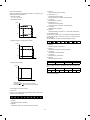
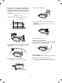
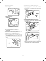
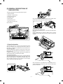
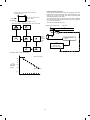
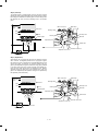
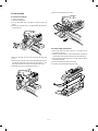
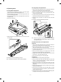
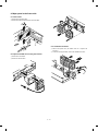
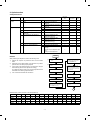
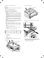
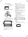
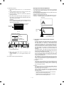
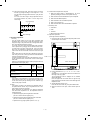
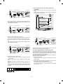
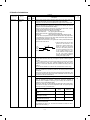
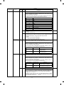
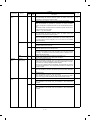
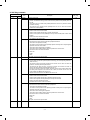
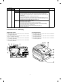
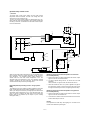
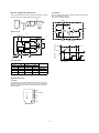
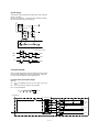
4) Change the height of the roller in No.4/5 mirror unit front
frame side to adjust the vertical image distortion.
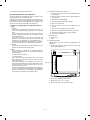
If the copy image is tilting as shown in sample (X) below,
lower No.4/5 mirror unit. If it is tilting as shown in sample (Y)
below, lift No.4/5 mirror unit.
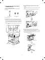
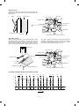
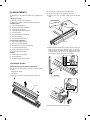
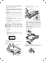
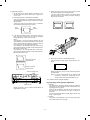
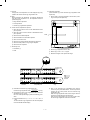
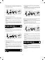
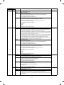
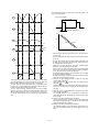
1) Set the test chart for image distortion adjustment on the
document glass, and make a normal copy on a paper of A4
or 8 1/2" x 11".
2) Check image distortion in the right and the left sides.
If the both vertical lines are in parallel with each other, the
right-left distortion balance is proper. (However, there may be
some distortion.)
If all the four angles are right angles, there in no distortion
and the following procedures are not required.
Small
distortion
Large
distortion
(X)
(Y)
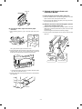
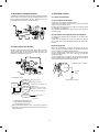
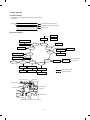
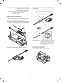
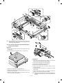
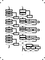
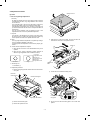
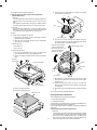
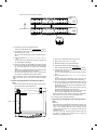
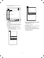
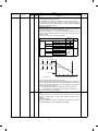
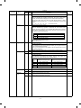
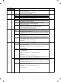
3) If the right-left distortion balance is improper, loosen the
fixing screw of No.2 scanner unit rail to change and adjust
the right-left balance of No.2 scanner unit rail.
(Note)
This procedure is to have the balance between the right
image distortion and the left image distortion, which does not
mean to eliminate the image distortion. Change the height of
No.2 scanner unit rail in the greater distortion side.
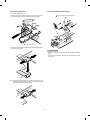
If the distortion in the lead edge side (when viewed in the
paper transport direction) is greater, change the height of the
left rail of No.2 scanner unit.
If the distortion in the rear edge side (when viewed in the
paper transport direction) is greater, change the height of the
right rail of No.2 scanner unit.
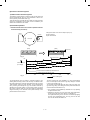
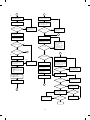
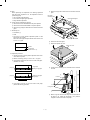
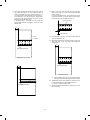
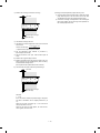
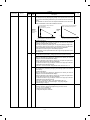
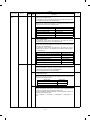
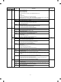
5) Make a copy to check the vertical image distortion.
If the four angles are right angles, the adjustment is completed.
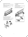
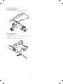
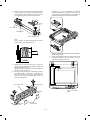
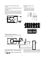
Change the right side
height of the rail.
Change the left side
height of the rail.
Repeat procedures 4) and 5) until the vertical image distortion is eliminated.
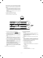
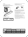
Scanner unit fixing screw
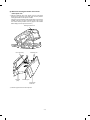
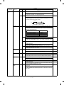
(Note) If a vertical image distortion is not eliminated with
procedure 4), change the overall height of No.2
scanner unit rail. Then repeat procedures 1) to 5).
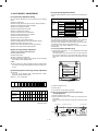
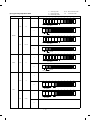
VII. Troubles caused by improper adjustment
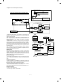
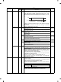
(4) Copy image center position adjustment
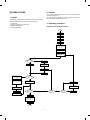
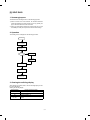
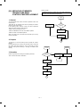
I. Summary
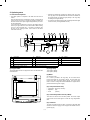
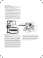
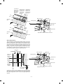
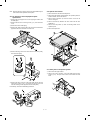
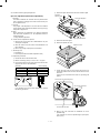
The optical axis is changed by changing the lens rail position to
optically align the document table and the vertical position of the
copy image on the copy paper.
When the lens rail position is changed, the lens position in the
front and the rear frame direction is changed to change the
optical axis.
As a result, the document table is optically aligned with the copy
image on the copy paper.
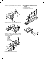
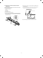
Scanner unit rail
Repeat procedures 2) and 3) until the right-left balance of
image distortion is proper.
II. Purpose
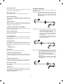
The purpose of this adjustment is to set the copy image center
at the vertical center of the copy paper.
7 – 12