1
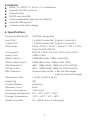
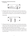
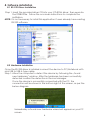
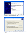
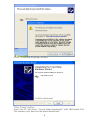
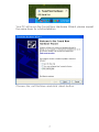
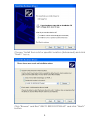
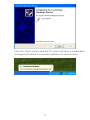
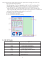
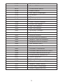
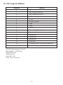
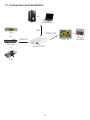
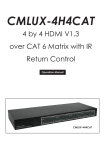
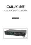
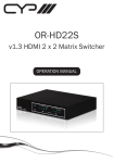
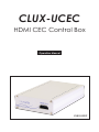
CLUX-UCEC HDMI CEC Control Box Operation Manual CLUX-UCEC Disclaimers The information in this manual has been carefully checked and is believed to be accurate. Cypress Technology assumes no responsibility for any infringements of patents or other rights of third parties which may result from its use. Cypress Technology assumes no responsibility for any inaccuracies that may be contained in this document. Cypress also makes no commitment to update or to keep current the information contained in this document. Cypress Technology reserves the right to make improvements to this document and/or product at any time and without notice. Copyright Notice No part of this document may be reproduced, transmitted, transcribed, stored in a retrieval system, or any of its part translated into any language or computer file, in any form or by any means - electronic, mechanical, magnetic, optical, chemical, manual, or otherwise - without express written permission and consent from Cypress Technology. © Copyright 2009 by Cypress Technology. All Rights Reserved. Version 1.0 January 2010 Trademark Acknowledgments All products or service names mentioned in this document may be trademarks of the companies with which they are associated. Safety Precautions Please read all instructions before attempting to unpack or install or operate this equipment, and before connecting the power supply. Please keep the following in mind as you unpack and install this equipment: Always follow basic safety precautions to reduce the risk of fire, electrical shock and injury to persons. To prevent fire or shock hazard, do not expose the unit to rain, moisture or install this product near water. Never spill liquid of any kind on or into this product. Never push an object of any kind into this product through module openings or empty slots, as you may damage parts. Do not attach the power supply cabling to building surfaces. Do not allow anything to rest on the power cabling or allow it to be abused by persons walking on it. To protect the equipment from overheating, do not block the slots and openings in the module housing that provide ventilation. Revision History Version No V1 Date 20100104 Summary of Change Preliminary Release Table of Contents 1. Introduction ……………………..……………………...…........….……. 1 2. Applications …………………..………………….……...................….. 1 3. Package Contents ………………………...........……….................… 1 4. System Requirements ……………..……….........………............……. 1 5. Features …………………………………………......……........…...…… 2 6. Specifications ………………………………...……..........………....…. 2 7. Operation Controls and Functions ……………...……..............…… 7.1 Front Panel .............................................................................. 3 7.2 Rear Panel .…………………………………..…….......…...….… 3 8. Software installation ……………...……..................................…… 8.1 RS-232 Driver Installation ........................................................ 4 8. 3 4 8.2 Hardware Application .……….......................................….… 4 8.3 Software Application .........................................................… 5 9. CEC OP Code .......................…......……………..........…..….......…... 6 10. CEC Logical Address ....................................................................... 8 11. 12. Connection and Installation ……………...……............................… Acronyms …...................................................................................... 9 10 1. Introduction The HDMI CEC Control Box is a convenient USB device allowing users to control various HDMI devices through their PC. Both sources and displays can be controlled, either with a PC or remote control. This device connects to the PC using a mini USB port, allowing plug and play simplicity and providing power for the device itself, so you don’t have to deal with any cumbersome cables. 2. Applications CEC system remote control over USB for HDMI devices 3. Package Contents CEC control box User Manual CD-ROM 4. System Requirements HDMI input source equipment with output to HDMI display that have a built in CEC function, HDMI cable, PC or laptop with built in RS-232 software and USB cables. 1 5. Features HDMI v1.3, HDCP v1.1 & DVI v1.0 compliance Supports full CEC functions Plug and play RS-232 over mini USB Power supplied through the mini USB port Supports EDID bypass Compact and stylish design 6. Specifications Frequency Bandwidth 2.25Gbps (single link) Input Port 1 x HDMI Female Port (Type A Connector) Output Port 1 x HDMI Female Port (Type A Connector) HDMI Audio PCM2, PCM5.1, PCM7.1, Dolby 5.1, DTS 5.1, DD+, Dolby TrueHD, DTS-HD Color Space RGB_24, YCbCr 4:4:4_24, YCbCr 4:2:2, xvYCC Deep Color 1080p 12 bits HDMI Cable In 1080p 8bits (6M), 1080p 12bits (6M) HDMI Cable Output 1080p 8bits (10M), 1080p 12bits (10M) HDMI Resolution 480i ~ 1080p 50/60, 1080p 24, VGA~WUXGA DVI Resolution 480i ~ 1080p 50/60, 1080p 24, VGA~WUXGA ESD Protection Human body mode: ± 8kV (air-discharge) ± 4kV (contact discharge) Dimensions (mm) 114 (W) x 65 (D) x 26 (H) Weight (g) 200 Chassis Material Aluminum Silkscreen Color Silver Power Consumption 2.5W (max) Operating Temperature 0˚C ~ 40˚C / 32˚F ~ 104˚F Storage Temperature -20˚C ~ 60˚C / -4˚F ~ 140˚F Relative Humidity 20 ~ 60% RH (non-condensing) 2 7. Operation Controls and Functions 7.1 Front Panel HDMI I / O CLUX-UCEC ① ① HDMI input/output: This slot is where you can connect the output port of your HDMI / DVI source (i.e., DVD, set-top box) or the input ports of an HDMI display using a HDMI / HDMI to DVI adaptor cable. When connecting with an input source, the other HDMI/O must connect with the output port of your display. You cannot control two sources/displays. 7.2 Rear Panel HDMI I/O USB ① ② ① HDMI input/output: This slot is where you can connect the output port of your HDMI / DVI source (i.e., DVD, set-top box) or the input port of an HDMI display using a HDMI / HDMI to DVI adaptor cable. When connecting with an input source, the other HDMI/O must connect with the output port of your display. You cannot control two sources/displays. ② USB communication port: This slot is where you connect a mini USB to USB A type cable to the PC/laptop when controlling the devices over RS-232. Detailed specifications are listed in next section. Also this port provides power for the device when the connected PC or laptop is turned on. However when not using RS-232 mode no power is needed, so it will bypass the system. 3 8. Software installation 8.1 RS-232 Driver Installation Step 1: Insert the provided driver CD into your CD-ROM driver, then execute the FIDIBUS file. Follow the on screen instructions to complete the instillation. NOTE: It is not necessary to install this application if users already have existing RS-232 software. 8.2 Hardware Installation Once the RS-232 driver is installed connect the device to PC/Notebook with mini USB to USB A type cable. Step 1: Allow the computer to detect the device by following the “found new hardware” window. After the hardware has been successfully detected confirm the detection in Device Manager. Once the device is successfully connected with the PC, the connection will be shown in the bottom right of the screen, as per the below diagram. Immediately a found new hardware wizard will appear on your PC screen. 4 Choose “No, not this time” and Click “Next” . Click “ Browse ” and find “ USB TO RS232 SOFTWAVE ” and click “Nest>”. 5 Click “Continue Anyway” button. Click “Finish” button Now the PC will show “Found New Hardware” with USB Serial Port. This means your device has been detected. 6 Your PC will re-run the Found New Hardware Wizard, please repeat the same steps for a full installation. Choose “No, not this time” and click “Next” button. 7 Choose “Install from a list or specific location (Advanced) and click “Next>” button. Click “Browse” and find “USB TO RS232 SOFTWAVE” and click “Next>” button. 8 Click the “Finish” button and the PC screen will show a confirmation message that advise a complete installation as shown below. 9 Step 2: Click START from the left bottom window and select Settings → Control panel → Performance and maintenance → System → System Properties → Hardware → Device Manager → Ports (COM & LPT) → USB Serial Port (COM) 8.3 Software Application Step 1: To install this program, please insert the included CD and double click CLUX_UCED_AP.exe. 10 Step 2: When the application launches (see below image) the user can select the following features. 1.RS-232 setting: ComPort designated for the CEC control with its BaudRate transmission, click connect to confirm this setting 2. CEC setting: i.e. DVD player sends active commands to a TV, Data Length would include Data Type (CEC), CEC Header (4F), CEC OPCode (82) and 5bytes of data. Press Transmit to confirm the setting (Detail setting please refers to section 9) 3. Common use CEC command. 4. CEC command window. 5. CEC command window setting. 9. CEC OP Code Value OpCode 0x04 <Image View On> 0x05 <Tuner Step Increment> 0x06 <Tuner Step Decrement> 0x07 <Tuner Device Status> 0x08 <Give Tuner Device Status> 0x09 <Record On> 0x0A <Record Status> 0x0B <Record Off> 11 0x0D <Text View On> 0x0F <Record TV Screen> 0x1A <Give Deck Status> 0x1B <Deck Status> 0x32 <Set Menu Language> 0x36 <Standby> 0x41 <Play> 0x42 <Deck Control> 0x44 <User Control Pressed> 0x46 <Give OSD Name> 0x47 <Set OSD Name> 0x64 <Set OSD String> 0x80 <Routing Change> 0x81 <Routing Information> 0x82 <Active Source> 0x83 <Give Physical Address> 0x84 <Report Physical Address> 0x85 <Request Active Source> 0x86 <Set Stream Path> 0x87 <Device Vendor ID> 0x89 <Vendor Command> 0x8A <Vendor Remote Button Down> 0x8B <Vendor Remote Button Up> 0x8C <Give Device Vendor ID> 0x8D <Menu Request> 0x8E <Menu Status> 0x8F <Give Device Power Status> 0x90 <Report Power Status> 0x91 <Get Menu Language> 0x93 <Select Digital Service> 12 10. CEC Logical Address Address Device 0 TV 1 Recording Device 1 2 Recording Device 2 3 STB1 4 DVD1 5 Audio System 6 STB2 7 STB3 8 DVD2 9 Recording Device 3 10 Reserved 11 Reserved 12 Reserved 13 Reserved 14 Free Use 15 Unregistered (as initiator address) Broadcast (as destination address) RS-232 transmission format: Baud Rate: 115200 bps Data Bit: 8 bits Parity: None Stop Bit: 1 bit Flow Control: None 13 11. Connection and Installation or PC Notebook USB DVD HDMI OUT or or LCD TV HDMI IN Blu-ray or CLUX-UCEC STB 14 Monitor A Acronyms Acronym Complete Term CEC Consumer Electronics Control DVI Digital Visual Interface EDID Extended Display Identification Data HDCP High-bandwidth Digital Content Protection HDMI High-Definition Multimedia Interface VGA Video Graphics Array WUXGA Wide Ultra Extended Graphics Array 15 CYPRESS TECHNOLOGY CO., LTD. Home page: http://www.cypress.com.tw 20100108 MPM-CLUXUCEC