1
Safety Summary
When you notice any of the unusual conditions listed below, immediately
terminate operation and disconnect the power cable.
Contact your local Agilent Technologies sales representative or
authorized service company for repair of the instrument. If you continue
to operate without repairing the instrument, there is a potential fire or
shock hazard for the operator.
n Instrument operates abnormally.
n Instrument emits abnormal noise, smell, smoke or a spark-like light
during the operation.
n Instrument generates high temperature or electrical shock during
operation.
n Power cable, plug, or receptacle on instrument is damaged.
n Foreign substance or liquid has fallen into the instrument.
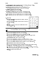
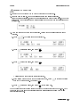
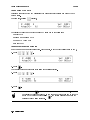
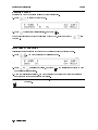
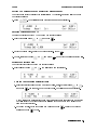
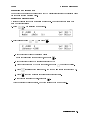
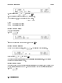
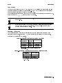
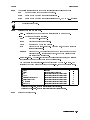
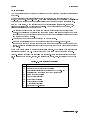
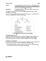
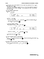
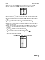
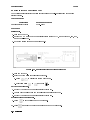
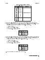
When you turn on the 4339B for the rst time, conrm the power line frequency is set
correctly.
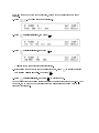
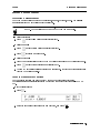
1. Press
. The following menu is displayed.
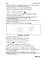
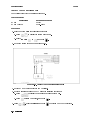
2. Press
until ``more'' blinks, and press
.
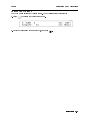
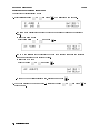
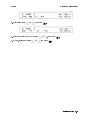
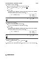
3. Press
until ``Line'' blinks, and press
.
A blinking item means that it is currently selected.
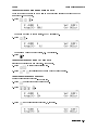
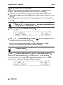
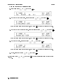
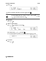
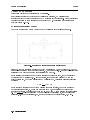
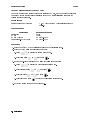
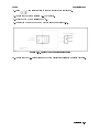
4. If the setting does not match the power line frequency, press
between ``50 Hz'' and ``60 Hz''. Then press
.
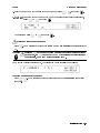
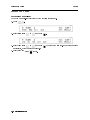
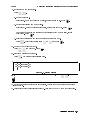
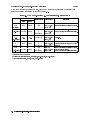
5. Press
until ``Exit'' blinks, and press
to toggle the setting
to exit this menu.
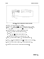
The power line frequency setting is stored and is not changed after reset or power-o. Once
you set it, you do not need to set the line frequency again as long as the same power line
frequency is being used.
Agilent 4339B High Resistance Meter
Operation Manual
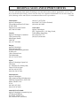
SERIAL NUMBERS
This manual applies directly to instruments with serial
number prex JP1KD, or rmware revision 1.04.
For additional important information about serial
numbers, read \Serial Number" in Appendix A.
Agilent Part No. 04339-90060
Printed in Japan March 2003
Ninth Edition
Notice
The information contained in this document is subject to change without notice.
This document contains proprietary information that is protected by copyright. All rights are
reserved. No part of this document may be photocopied, reproduced, or translated to another
language without the prior written consent of the Agilent Technologies.
Agilent Technologies Japan, Ltd.
Component Test PGU-Kobe
1-3-2, Murotani, Nishi-ku, Kobe-shi,
Hyogo, 651-2241 Japan
c 1996, 1998, 1999, 2000, 2001, 2002, 2003 Agilent Technologies Japan, Ltd.
4339B
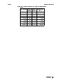
Manual Printing History
March 1996 : : : : : : : : : : : : : : : : : : : : : : : : : : : : : : : : : : : : : : : : : : : First Edition (part number:
December 1996 : : : : : : : : : : : : : : : : : : : : : : : : : : : : : : : : : : : : Second Edition (part number:
June 1998 : : : : : : : : : : : : : : : : : : : : : : : : : : : : : : : : : : : : : : : : : : : Third Edition (part number:
August 1998 : : : : : : : : : : : : : : : : : : : : : : : : : : : : : : : : : : : : : : : : Fourth Edition (part number:
July 1999 : : : : : : : : : : : : : : : : : : : : : : : : : : : : : : : : : : : : : : : : : : : : Fifth Edition (part number:
March 2000 : : : : : : : : : : : : : : : : : : : : : : : : : : : : : : : : : : : : : : : : : : Sixth Edition (part number:
January 2001 : : : : : : : : : : : : : : : : : : : : : : : : : : : : : : : : : : : : : Seventh Edition (part number:
September 2002 : : : : : : : : : : : : : : : : : : : : : : : : : : : : : : : : : : : : Eighth Edition (part number:
March 2003 : : : : : : : : : : : : : : : : : : : : : : : : : : : : : : : : : : : : : : : : : Ninth Edition (part number:
04339-90010)
04339-90020)
04339-90030)
04339-90040)
04339-90050)
04339-90050)
04339-90050)
04339-90050)
04339-90060)
iii
4339B
Safety Summary
The following general safety precautions must be observed during all phases of operation,
service, and repair of this instrument. Failure to comply with these precautions or with specic
WARNINGS elsewhere in this manual may impair the protection provided by the equipment.
In addition it violates safety standards of design, manufacture, and intended use of the
instrument.
The Agilent Technologies assumes no liability for the customer's failure to comply with these
requirements.
Note
4339B is designed for use in INSTALLATION CATEGORY II according to IEC
61010-1 and POLLUTION DEGREE 1 according to IEC 61010-1 and IEC 60664-1.
4339B is an INDOOR USE product.
Note
LEDs in 4339B are Class 1 in accordance with IEC60825-1.
CLASS 1 LED PRODUCT
Ground The Instrument
To avoid electric shock hazard, the instrument chassis and cabinet must be connected to a
safety earth ground by the supplied power cable with earth blade.
DO NOT Operate In An Explosive Atmosphere
Do not operate the instrument in the presence of ammable gasses or fumes. Operation of any
electrical instrument in such an environment constitutes a denite safety hazard.
Keep Away From Live Circuits
Operating personnel must not remove instrument covers. Component replacement and internal
adjustments must be made by qualied maintenance personnel. Do not replace components
with the power cable connected. Under certain conditions, dangerous voltages may exist even
with the power cable removed. To avoid injuries, always disconnect power and discharge
circuits before touching them.
DO NOT Service Or Adjust Alone
Do not attempt internal service or adjustment unless another person, capable of rendering rst
aid and resuscitation, is present.
DO NOT Substitute Parts Or Modify Instrument
Because of the danger of introducing additional hazards, do not install substitute parts or
perform unauthorized modications to the instrument. Return the instrument to a Agilent
Technologies Sales and Service Oce for service and repair to ensure that safety features are
maintained.
iv
4339B
Dangerous Procedure Warnings
Warnings , such as the example below, precede potentially dangerous procedures throughout
this manual. Instructions contained in the warnings must be followed.
Warning
Dangerous voltages, capable of causing death, are present in this
instrument. Use extreme caution when handling, testing, and adjusting
this instrument.
v
4339B
Certication
Agilent Technologies certies that this product met its published specications at the time
of shipment from the factory. Agilent Technologies further certies that its calibration
measurements are traceable to the United States National Institute of Standards and
Technology, to the extent allowed by the Institution's calibration facility, or to the calibration
facilities of other International Standards Organization members.
Warranty
This Agilent Technologies instrument product is warranted against defects in material and
workmanship for a period of one year from the date of shipment, except that in the case of
certain components listed in General Information of this manual, the warranty shall be for the
specied period. During the warranty period, Agilent Technologies will, at its option, either
repair or replace products that prove to be defective.
For warranty service or repair, this product must be returned to a service facility designated by
Agilent Technologies. Buyer shall prepay shipping charges to Agilent Technologies and Agilent
Technologies shall pay shipping charges to return the product to Buyer. However, Buyer shall
pay all shipping charges, duties, and taxes for products returned to Agilent Technologies from
another country.
Agilent Technologies warrants that its software and rmware designated by Agilent
Technologies for use with an instrument will execute its programming instruction when
property installed on that instrument. Agilent Technologies does not warrant that the operation
of the instrument, or software, or rmware will be uninterrupted or error free.
Limitation Of Warranty
The foregoing warranty shall not apply to defects resulting from improper or inadequate
maintenance by Buyer, Buyer-supplied software or interfacing, unauthorized modication or
misuse, operation outside the environmental specications for the product, or improper site
preparation or maintenance.
No other warranty is expressed or implied. Agilent Technologies specically disclaims the
implied warranties of merchantability and tness for a particular purpose.
vi
4339B
Exclusive Remedies
The remedies provided herein are buyer's sole and exclusive remedies. Agilent Technologies
shall not be liable for any direct, indirect, special, incidental, or consequential damages,
whether based on contract, tort, or any other legal theory.
Assistance
Product maintenance agreements and other customer assistance agreements are available for
Agilent Technologies products.
For any assistance, contact your nearest Agilent Technologies Sales and Service Oce.
Addresses are provided at the back of this manual.
vii
4339B
Safety Symbols
General denitions of safety symbols used on equipment or in manuals are listed below.
Instruction manual symbol: the product is marked with this symbol when it is
necessary for the user to refer to the instruction manual.
Alternating current.
Direct current.
On (Supply).
O (Supply).
This Warning sign denotes a hazard. It calls attention to a procedure, practice,
condition or the like, which, if not correctly performed or adhered to, could
result in injury or death to personnel.
This Caution sign denotes a hazard. It calls attention to a procedure, practice,
condition or the like, which, if not correctly performed or adhered to, could
result in damage to or destruction of part or all of the product.
Note denotes important information. It calls attention to a procedure,
practice, condition or the like, which is essential to highlight.
Axed to product containing static sensitive devices use anti-static handling
procedures to prevent electrostatic discharge damage to component.
Caution, risk of electric shock : Terminals which may be supplied from the
interior of the equipment at a voltage exceeding 1 kV, or allow connection to a
voltage exceeding 1 kV are marked with this symbol.
viii
4339B
Herstellerbescheinigung
GERSCHEMISSION
LpA < 70 dB
am Arbeitsplatz
normaler Betrieb
nach DIN 45635 T. 19
Manufacturer's Declaration
ACOUSTIC NOISE EMISSION
LpA < 70 dB
operator position
normal operation
per ISO 7779
ix
4339B
Contents of this Manual
Chapter 1
Provides the product overview and basic measurement procedure. First time users of the
4339B should read this chapter rst.
Chapter 2
Shows how to operate the 4339B from its front panel. Refer to this chapter when you wish to
learn about operations using the front panel keys.
Chapter 3
Describes all functions of this instrument. Refer to this chapter when you wish to learn about
the functions of the front and rear panel keys and terminals.
Chapter 4
Shows how to remotely operate the 4339B. Refer to this chapter when you wish to learn about
the procedures for remotely operating the 4339B via the GPIB.
Chapter 5
Contains complete information on remotely operating the 4339B via the GPIB. Refer to this
chapter when you wish to learn about the GPIB commands, status reporting mechanism, trigger
system, and data transmission format.
Chapter 6
Provides a measurement example using the 4339B.
Chapter 7
Provides information for eective operations.
Chapter 8
Provides specications, reference data, and other general information.
Chapter 9
Describes how to verify the specications.
x
4339B
Appendix A
Contains information on using the 4339Bs which were manufactured before this manual was
printed.
Appendix B
Contains information which is required for using the handler interface. Before using the
handler interface, read this appendix and set the handler interface input/output signal.
Appendix C
The summary of operations when the 4339B detects OVLD (Overload), Over-Current (exceeding
current limit), or N.C. (No-Contact).
xi
Contents
1. Getting Started
Introduction . . . . . . . . . . . . . . . . . . . . .
Overview . . . . . . . . . . . . . . . . . . . . . .
Features . . . . . . . . . . . . . . . . . . . . .
Accessories Available . . . . . . . . . . . . . . . .
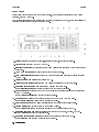
Front Panel . . . . . . . . . . . . . . . . . . . .
Display . . . . . . . . . . . . . . . . . . . . . .
Rear Panel . . . . . . . . . . . . . . . . . . . .
Initial Inspection . . . . . . . . . . . . . . . . . . .
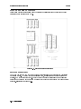
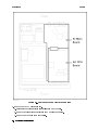
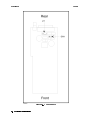
Providing clearance to dissipate heat at installation site
Instruction for Cleaning . . . . . . . . . . . . . . .
Power Cable . . . . . . . . . . . . . . . . . . . . .
Preparation for Use . . . . . . . . . . . . . . . . .
Power Requirements . . . . . . . . . . . . . . . .
.
.
.
.
.
.
.
.
.
.
.
.
.
.
.
.
.
.
.
.
.
.
.
.
.
.
.
.
.
.
.
.
.
.
.
.
.
.
.
.
.
.
.
.
.
.
.
.
.
.
.
.
.
.
.
.
.
.
.
.
.
.
.
.
.
.
.
.
.
.
.
.
.
.
.
.
.
.
.
.
.
.
.
.
.
.
.
.
.
.
.
.
.
.
.
.
.
.
.
.
.
.
.
.
.
.
.
.
.
.
.
.
.
.
.
.
.
.
.
.
.
.
.
.
.
.
.
.
.
.
.
.
.
.
.
.
.
.
.
.
.
.
.
.
.
.
.
.
.
.
.
.
.
.
.
.
1-1
1-2
1-2
1-3
1-4
1-6
1-7
1-8
1-8
1-9
1-10
1-12
1-12
Fuse . . . . . . . . . . . . . . . . . . . . . . . . . . . . . . . . .
1-12
Turning ON the 4339B . . . . . . . . . .
Power-On Self Test . . . . . . . . . . . . . .
Using Front Panel Keys . . . . . . . . . . . . .
Direct Execution Type Keys . . . . . . . . . .
Toggle Type Keys . . . . . . . . . . . . . . .
Selection Type Keys . . . . . . . . . . . . . .
Value Setup Type Keys . . . . . . . . . . . . .
Value Setup Using Numeric Keys . . . . . . .
Value Setup Using Maximum and Minimum Keys
Value Setup Using Down and Up Arrow Keys .
Value Change Using Back Space Key . . . . .
Basic Operation . . . . . . . . . . . . . . . . .
.
.
.
.
.
.
.
.
.
.
.
.
.
.
.
.
.
.
.
.
.
.
.
.
.
.
.
.
.
.
.
.
.
.
.
.
.
.
.
.
.
.
.
.
.
.
.
.
.
.
.
.
.
.
.
.
.
.
.
.
.
.
.
.
.
.
.
.
.
.
.
.
.
.
.
.
.
.
.
.
.
.
.
.
.
.
.
.
.
.
.
.
.
.
.
.
.
.
.
.
.
.
.
.
.
.
.
.
.
.
.
.
.
.
.
.
.
.
.
.
.
.
.
.
.
.
.
.
.
.
.
.
.
.
.
.
.
.
.
.
.
.
.
.
.
.
.
.
.
.
.
.
.
.
.
.
.
.
.
.
.
.
.
.
.
.
.
.
1-13
1-14
1-15
1-15
1-15
1-15
1-16
1-16
1-17
1-17
1-17
1-18
Connecting Test Fixture .
Floating DUT Measurement .
Grounded DUT Measurement
Resetting 4339B . . . . . . .
Performing Calibration . . . .
Setting Test Voltage . . . . .
.
.
.
.
.
.
.
.
.
.
.
.
.
.
.
.
.
.
.
.
.
.
.
.
.
.
.
.
.
.
.
.
.
.
.
.
.
.
.
.
.
.
.
.
.
.
.
.
.
.
.
.
.
.
.
.
.
.
.
.
.
.
.
.
.
.
.
.
.
.
.
.
.
.
.
.
.
.
.
.
.
.
.
.
.
.
.
.
.
.
.
.
.
.
.
.
.
.
.
.
.
.
.
.
.
.
.
.
.
.
.
.
.
.
.
.
.
.
.
.
.
.
.
.
.
.
.
.
.
.
.
.
.
.
.
.
.
.
.
.
.
.
.
.
1-19
1-19
1-19
1-20
1-20
1-21
Performing OPEN Correction . . . . .
Selecting Measurement Parameter . . . . .
Selecting Measurement Range . . . . . . .
Auto Range mode . . . . . . . . . . . .
Hold Range mode . . . . . . . . . . . .
Changing the Range in Hold Range mode
.
.
.
.
.
.
.
.
.
.
.
.
.
.
.
.
.
.
.
.
.
.
.
.
.
.
.
.
.
.
.
.
.
.
.
.
.
.
.
.
.
.
.
.
.
.
.
.
.
.
.
.
.
.
.
.
.
.
.
.
.
.
.
.
.
.
.
.
.
.
.
.
.
.
.
.
.
.
.
.
.
.
.
.
.
.
.
.
.
.
.
.
.
.
.
.
.
.
.
.
.
.
1-22
1-23
1-23
1-23
1-23
1-23
Applying Test Voltage . . . . . . . . . . . . . . . . . . . . . . . . . .
1-24
Contents-1
Turning OFF Test Voltage . . . . . . . . . . . . . . . . . . . . . . . .
2. Operating the 4339B
1-24
Introduction . . . . . . . . . . . . . . . . . . . . . .
Measurement Conguration . . . . . . . . . . . . . .
Selecting the Measurement Time Mode . . . . . . . .
Setting the Averaging Rate . . . . . . . . . . . . . .
Setting the Trigger Delay Time . . . . . . . . . . . .
Setting the Parameters for Resistivity Measurement . .
Entering Thickness of the DUT . . . . . . . . . . .
Setting the Electrode Size . . . . . . . . . . . . .
Making a Measurement . . . . . . . . . . . . . . . . .
Triggering a Measurement . . . . . . . . . . . . . .
Using the Comparator Function . . . . . . . . . . . .
Displaying Deviation Data . . . . . . . . . . . . . .
Setting the Reference Value . . . . . . . . . . . .
Selecting the Deviation Display Mode . . . . . . . .
Using the Measurement Sequence Function . . . . . .
Selecting the Measurement Sequence Mode . . . . .
Setting the Measurement Sequence Mode Parameters
Setting Time Display Function . . . . . . . . . . .
.
.
.
.
.
.
.
.
.
.
.
.
.
.
.
.
.
.
.
.
.
.
.
.
.
.
.
.
.
.
.
.
.
.
.
.
.
.
.
.
.
.
.
.
.
.
.
.
.
.
.
.
.
.
.
.
.
.
.
.
.
.
.
.
.
.
.
.
.
.
.
.
.
.
.
.
.
.
.
.
.
.
.
.
.
.
.
.
.
.
.
.
.
.
.
.
.
.
.
.
.
.
.
.
.
.
.
.
.
.
.
.
.
.
.
.
.
.
.
.
.
.
.
.
.
.
.
.
.
.
.
.
.
.
.
.
.
.
.
.
.
.
.
.
.
.
.
.
.
.
.
.
.
.
.
.
.
.
.
.
.
.
.
.
.
.
.
.
.
.
.
.
.
.
.
.
.
.
.
.
.
.
.
.
.
.
.
.
.
.
.
.
.
.
.
.
.
.
2-1
2-2
2-2
2-2
2-2
2-3
2-3
2-3
2-5
2-5
2-5
2-7
2-7
2-8
2-9
2-9
2-9
2-10
Starting Measurement Sequence . . . . . . .
Aborting Measurement Sequence . . . . . . . . .
Setting Contact Check . . . . . . . . . . . . . . .
Reading the Limit Data of Contact Check Function
Reading the Capacitance Data at DUT Measurement
Setting Current Limit . . . . . . . . . . . . . . .
Setting Current Monitor . . . . . . . . . . . . . .
Setting Beeper Mode . . . . . . . . . . . . . . . .
Setting Display Mode and Display Format . . . . . .
Changing Measurement Settings Display Mode . . . .
Saving and Recalling Instrument Settings . . . . . .
Locking Out the Front Panel Keys . . . . . . . . .
Selecting Local Mode . . . . . . . . . . . . . . . .
Setting the GPIB Address . . . . . . . . . . . . . .
Printing Measurement Data . . . . . . . . . . . . .
Setting the Oset-Error Canceling Function . . . . .
Testing the 4339B . . . . . . . . . . . . . . . . . .
Performing a Self-Test . . . . . . . . . . . . . . .
Testing the Front Panel Key's Functionality . . . . .
If You Have a Problem . . . . . . . . . . . . . . . .
If the Display is Blank and the 4339B Appears Dead .
If an Error Message is Displayed . . . . . . . . . .
If the 4339B does not Accept Any Key Input . . . .
If the Indicated Value is not Stable . . . . . . . . .
If You Find Yourself Lost When Operating the 4339B .
.
.
.
.
.
.
.
.
.
.
.
.
.
.
.
.
.
.
.
.
.
.
.
.
.
.
.
.
.
.
.
.
.
.
.
.
.
.
.
.
.
.
.
.
.
.
.
.
.
.
.
.
.
.
.
.
.
.
.
.
.
.
.
.
.
.
.
.
.
.
.
.
.
.
.
.
.
.
.
.
.
.
.
.
.
.
.
.
.
.
.
.
.
.
.
.
.
.
.
.
.
.
.
.
.
.
.
.
.
.
.
.
.
.
.
.
.
.
.
.
.
.
.
.
.
.
.
.
.
.
.
.
.
.
.
.
.
.
.
.
.
.
.
.
.
.
.
.
.
.
.
.
.
.
.
.
.
.
.
.
.
.
.
.
.
.
.
.
.
.
.
.
.
.
.
.
.
.
.
.
.
.
.
.
.
.
.
.
.
.
.
.
.
.
.
.
.
.
.
.
.
.
.
.
.
.
.
.
.
.
.
.
.
.
.
.
.
.
.
.
.
.
.
.
.
.
.
.
.
.
.
.
.
.
.
.
.
.
.
.
.
.
.
.
.
.
.
.
.
.
.
.
.
.
.
.
.
.
.
.
.
.
.
.
.
.
.
.
.
.
.
.
.
.
.
2-11
2-11
2-12
2-13
2-13
2-14
2-14
2-14
2-16
2-17
2-18
2-18
2-18
2-19
2-19
2-19
2-20
2-20
2-21
2-22
2-22
2-22
2-22
2-22
2-22
Contents-2
.
.
.
.
.
.
.
.
.
.
.
.
.
.
.
.
.
.
.
.
.
.
.
.
.
3. Function Reference
Introduction . . . . . . . .
Front Panel . . . . . . . .
Display . . . . . . . . .
LINE Switch . . . . . . .
Interlock Connector . . .
UNKNOWN Terminals
.
.
.
.
.
.
.
.
.
.
.
.
.
.
.
.
.
.
.
.
.
.
.
.
.
.
.
.
.
.
.
.
.
.
.
.
.
.
.
.
.
.
.
.
.
.
.
.
.
.
.
.
.
.
.
.
.
.
.
.
.
.
.
.
.
.
.
.
.
.
.
.
.
.
.
.
.
.
.
.
.
.
.
.
.
.
.
.
.
.
.
.
.
.
.
.
.
.
.
.
.
.
.
.
.
.
.
.
.
.
.
.
.
.
.
.
.
.
.
.
.
.
.
.
.
.
.
.
.
.
.
.
.
.
.
.
.
.
.
.
.
.
.
.
.
.
.
.
.
.
3-1
3-2
3-2
3-3
3-3
3-4
High Voltage Indicator . . . . . . . . . . . . . . . . . . . . . . . .
3-4
V Output Key
. . . . .
V Output Indicator . . . . . . . .
Source Voltage key
. . . . .
Current Limit Key
. .
Measurement Time key
. . .
Average key
. . . . .
Measurement Sequence Mode Key
Single Mode . . . . . . . . . .
Continuous mode . . . . . . .
Program Key
. . . . .
Time Display Function . . . . .
Measurement Parameter Key
Electrode Size Key
. .
Show Setting Key
. . . . .
Current Monitor Key
.
Auto/Hold Range Key
. . .
Range Setup Key
. . .
.
.
.
.
.
.
.
.
.
.
.
.
.
.
.
.
.
.
.
.
.
.
.
.
.
.
.
.
.
.
.
.
.
.
.
.
.
.
Trigger Key
. . . . . . .
Sequence Abort Key
. . .
Local Key
. . . . . . . . . .
Address Key
. . . . . .
Trigger Mode Key
. . . . . .
Delay Key
. . . . . . .
. . . . . . . . . .
Recall Key
Save Key
. . . . . . . .
Comparator Limit Keys
.
Left/Down and Right/Up Arrow Keys
0, . . . , 9, .(point), 0(minus) Keys
Shift Key
. . . . . . . . . .
Exponential Key
. . . . . . .
.
.
.
.
.
.
.
.
.
.
.
.
.
.
.
.
.
.
.
.
.
.
.
.
.
.
.
.
.
.
.
.
.
.
.
.
.
.
.
.
.
.
.
.
.
.
.
.
.
.
.
.
.
.
.
.
.
.
.
.
.
.
.
.
.
.
.
.
.
.
.
.
.
.
.
.
.
.
.
.
.
.
.
.
.
.
.
.
.
.
.
.
.
.
.
.
.
.
.
.
.
.
.
.
.
.
.
.
.
.
.
.
.
.
.
.
.
.
.
.
.
.
.
.
.
.
.
.
.
.
.
.
.
.
.
.
.
.
.
.
.
.
.
.
.
.
.
.
.
.
.
.
.
.
.
.
.
.
.
.
.
.
.
.
.
.
.
.
.
.
.
.
.
.
.
.
.
.
.
.
.
.
.
.
.
.
.
.
.
.
.
.
.
.
.
.
.
.
.
.
.
.
.
.
.
.
.
.
.
.
.
.
.
.
.
.
.
.
.
.
.
.
.
.
.
.
.
.
.
.
.
.
.
.
.
.
.
.
.
.
.
.
.
.
.
.
.
.
.
.
.
.
.
.
.
.
.
.
.
.
.
.
.
.
.
.
.
.
.
.
.
.
.
.
.
.
.
.
.
.
.
.
.
.
.
.
.
.
.
.
.
.
.
.
.
.
.
.
.
.
.
.
.
.
.
.
.
.
.
.
.
.
.
.
.
.
.
.
.
.
.
.
.
.
.
.
.
.
.
.
.
.
.
.
.
.
.
.
.
.
.
.
.
.
.
.
.
.
.
.
.
.
.
.
.
.
.
.
.
.
.
.
.
.
.
.
.
.
.
.
.
.
.
.
.
.
.
.
.
.
.
.
.
.
.
.
.
.
.
.
.
.
.
.
.
.
.
.
.
.
.
.
.
.
.
.
.
.
.
.
.
.
.
.
.
.
.
.
.
.
.
3-4
3-5
3-5
3-5
3-5
3-5
3-6
3-6
3-6
3-7
3-8
3-8
3-8
3-10
3-10
3-10
3-10
.
.
.
.
.
.
.
.
.
.
...
.
. . . . . . . . . . . .
. . . . . . . . . . . .
.
.
.
.
.
.
.
.
.
.
.
.
.
.
.
.
.
.
.
.
.
.
.
.
.
.
.
.
.
.
.
.
.
.
.
.
.
.
.
.
.
.
.
.
.
.
.
.
.
.
.
.
.
.
.
.
.
.
.
.
.
.
.
.
.
.
.
.
.
.
.
.
.
.
.
.
.
.
.
.
.
.
.
.
.
.
.
.
.
.
.
.
.
.
.
.
.
.
.
.
.
.
.
.
3-11
3-11
3-11
3-11
3-12
3-12
3-12
3-12
3-12
3-13
3-13
3-13
3-13
Contents-3
Back Space Key
. . . . . . . . . . . . . . . . . .
Enter Key
. . . . . . . . . . . . . . . . . . . . .
Minimum Key
. . . . . . . . . . . . . . . . .
Maximum Key
. . . . . . . . . . . . . . . .
Open Key
. . . . . . . . . . . . . . . . . . .
Calibration Key
. . . . . . . . . . . . . . . .
Comparator On/O Key
. . . . . . . . . . . .
Contact Check Key
. . . . . . . . . . . . . .
Display Mode Key
. . . . . . . . . . . . . . .
Key Lock Key
. . . . . . . . . . . . . . . . .
Reset Key
. . . . . . . . . . . . . . . . . . .
Conguration Key
. . . . . . . . . . . . . . .
Rear Panel . . . . . . . . . . . . . . . . . . . . . . . .
External Trigger . . . . . . . . . . . . . . . . . . . . .
LINE Fuse Holder . . . . . . . . . . . . . . . . . . . .
LINE Voltage Selector . . . . . . . . . . . . . . . . . .
Power Cord Receptacle . . . . . . . . . . . . . . . . . .
Power Cord . . . . . . . . . . . . . . . . . . . . . .
Serial Number Plate . . . . . . . . . . . . . . . . . . .
Handler Interface . . . . . . . . . . . . . . . . . . . .
Specications . . . . . . . . . . . . . . . . . . . . .
GPIB Interface . . . . . . . . . . . . . . . . . . . . .
Theory of Operation . . . . . . . . . . . . . . . . . . . .
Overall Measurement Theory . . . . . . . . . . . . . . .
Overall Block Diagram . . . . . . . . . . . . . . . . . .
Grounded and Ungrounded DUT Measurement Conguration
4. Remote Operation
Introduction . . . . . . . . . . . . . . . . . . .
Getting Started . . . . . . . . . . . . . . . . .
Input/Output Statements . . . . . . . . . . . .
Reading the GPIB Address . . . . . . . . . . .
Sending a Remote Command . . . . . . . . . .
Returning to Local Mode . . . . . . . . . . . .
Query Commands . . . . . . . . . . . . . . .
Getting Data from the 4339B . . . . . . . . . .
To Control the 4339B from an External Computer
To Set Up the 4339B . . . . . . . . . . . . . .
To Reset the 4339B . . . . . . . . . . . . .
To Set the Power LINE Frequency . . . . . .
To Select the Measurement Parameter . . . . .
To Set the Test Voltage . . . . . . . . . . . .
To Apply the Test Voltage . .
To Set the Current Limit . . . . .
To Select Measurement Time Mode
To Perform Calibration . . . . . .
To Perform OPEN Correction . . .
To Select the Measurement Range .
Contents-4
.
.
.
.
.
.
.
.
.
.
.
.
.
.
.
.
.
.
.
.
.
.
.
.
.
.
.
.
.
.
.
.
.
.
.
.
.
.
.
.
.
.
.
.
.
.
.
.
.
.
.
.
.
.
.
.
.
.
.
.
.
.
.
.
.
.
.
.
.
.
.
.
.
.
.
.
.
.
.
.
.
.
.
.
.
.
.
.
.
.
.
.
.
.
.
.
.
.
.
.
.
.
.
.
.
.
.
.
.
.
.
.
.
.
.
.
.
.
.
.
.
.
.
.
.
.
.
.
.
.
.
.
.
.
.
.
.
.
.
.
.
.
.
.
.
.
.
.
.
.
.
.
.
.
.
.
.
.
.
.
.
.
.
.
.
.
.
.
.
.
.
.
.
.
.
.
.
.
.
.
.
.
.
.
.
.
.
.
.
.
.
.
.
.
.
.
.
.
.
.
.
.
.
.
.
.
.
.
.
.
.
.
.
.
.
.
.
.
.
.
.
.
.
.
.
.
.
.
.
.
.
.
.
.
.
.
.
.
.
.
.
.
.
.
.
.
.
.
.
.
.
.
.
.
.
.
.
.
.
.
.
.
.
.
.
.
.
.
.
.
3-13
3-13
3-13
3-13
3-14
3-14
3-14
3-15
3-16
3-16
3-17
3-18
3-20
3-20
3-21
3-21
3-21
3-21
3-21
3-22
3-22
3-25
3-26
3-26
3-27
3-28
.
.
.
.
.
.
.
.
.
.
.
.
.
.
.
.
.
.
.
.
.
.
.
.
.
.
.
.
.
.
.
.
.
.
.
.
.
.
.
.
.
.
.
.
.
.
.
.
.
.
.
.
.
.
.
.
.
.
.
.
.
.
.
.
.
.
.
.
.
.
.
.
.
.
.
.
.
.
.
.
.
.
.
.
.
.
.
.
.
.
.
.
.
.
.
.
.
.
.
.
.
.
.
.
.
.
.
.
.
.
.
.
.
.
.
.
.
.
.
.
.
.
.
.
.
.
.
.
.
.
.
.
.
.
.
.
.
.
.
.
.
.
.
.
.
.
.
.
.
.
.
.
.
.
.
.
.
.
.
.
.
.
.
.
.
.
.
.
.
.
.
.
.
.
.
.
.
.
.
.
.
.
.
.
.
.
.
.
.
.
.
.
.
.
.
.
4-1
4-2
4-2
4-2
4-2
4-2
4-3
4-3
4-4
4-5
4-5
4-5
4-5
4-5
.
.
.
.
.
.
.
.
.
.
.
.
.
.
.
.
.
.
.
.
.
.
.
.
.
.
.
.
.
.
.
.
.
.
.
.
.
.
.
.
.
.
.
.
.
.
.
.
.
.
.
.
.
.
.
.
.
.
.
.
.
.
.
.
.
.
.
.
.
.
.
.
.
.
.
.
.
.
.
.
.
.
.
.
4-6
4-6
4-6
4-6
4-7
4-7
To Set the Averaging Rate . . . . . . . . . . . . . . . . . . . . . . . .
To Set Trigger Delay Time . . . . . . . . . . . . . . . . . . . . . . . .
To Set the Parameters for Resistivity Measurements . . . . . . . . . . . .
To Set Beeper Mode . . . . . . . . . . . . . . . . . . . . . . . . . . .
To Lock Out the Front Panel Keys . . . . . . . . . . . . . . . . . . . .
To Check Contact Integrity at the Test Fixture . . . . . . . . . . . . . . .
To Use the Comparator Function . . . . . . . . . . . . . . . . . . . . . .
To Display a Deviation Measurement . . . . . . . . . . . . . . . . . . . .
To Set the Oset-Error Canceling Function . . . . . . . . . . . . . . . . .
To Wait Until Previously Sent Commands are Completed . . . . . . . . . .
To Get the Current Instrument Settings . . . . . . . . . . . . . . . . . . .
To Save and Recall Instrument Settings . . . . . . . . . . . . . . . . . . .
To Trigger a Measurement . . . . . . . . . . . . . . . . . . . . . . . . . .
Waiting For Completion Of Measurement (detecting completion of measurement)
Sample program . . . . . . . . . . . . . . . . . . . . . . . . . . . . . .
Reading Out Measured Result . . . . . . . . . . . . . . . . . . . . . . . . .
Reading out measured result using *TRG command . . . . . . . . . . . . .
Reading out measured result using :FETC? command . . . . . . . . . . . . .
Data Retrieval . . . . . . . . . . . . . . . . . . . . . . . . . . . . . . .
To Retrieve Data Eciently . . . . . . . . . . . . . . . . . . . . . . . . .
To Use Data Buer . . . . . . . . . . . . . . . . . . . . . . . . . . . . .
To Perform a Measurement Sequence . . . . . . . . . . . . . . . . .
Other Features . . . . . . . . . . . . . . . . . . . . . . . . . . . . . . .
To Test the 4339B . . . . . . . . . . . . . . . . . . . . . . . . . . . . .
To Read the Error Queue . . . . . . . . . . . . . . . . . . . . . . . . . .
To Report the Instrument's Status . . . . . . . . . . . . . . . . . . . . . .
4-7
4-7
4-8
4-8
4-8
4-8
4-9
4-9
4-9
4-9
4-10
4-10
4-11
4-12
4-13
4-14
4-15
4-19
4-23
4-24
4-24
4-25
4-26
4-26
4-26
4-26
Sample Program . . . . . . . . . . . . . . . . . . . . . . . . . . . .
If You Have a Problem . . . . . . . . . . . . . . . . . . . . . . . . . . . .
If the 4339B Hangs Up When You Send the ABORt Command . . . . . . . . .
4-28
4-30
4-30
5. GPIB Reference
Introduction . . . . . . . . . . . . . . . . . . . . . . . . . . . . .
GPIB Commands . . . . . . . . . . . . . . . . . . . . . . . . . . .
Common Commands . . . . . . . . . . . . . . . . . . . . . . . .
Subsystem Commands . . . . . . . . . . . . . . . . . . . . . . .
Sybsystem Command Tree . . . . . . . . . . . . . . . . . . . . .
Program Message Syntax . . . . . . . . . . . . . . . . . . . . . .
Command Abbreviations . . . . . . . . . . . . . . . . . . . . . .
Case . . . . . . . . . . . . . . . . . . . . . . . . . . . . . . .
Program Message Terminator . . . . . . . . . . . . . . . . . . . .
Common Command Syntax . . . . . . . . . . . . . . . . . . . . .
Subsystem Command Syntax . . . . . . . . . . . . . . . . . . . .
Parameters . . . . . . . . . . . . . . . . . . . . . . . . . . . .
Parameter Types . . . . . . . . . . . . . . . . . . . . . . . . .
Multiple Messages . . . . . . . . . . . . . . . . . . . . . . . . .
Query and Response Message Syntax . . . . . . . . . . . . . . . .
Command Reference . . . . . . . . . . . . . . . . . . . . . . . . .
Notations . . . . . . . . . . . . . . . . . . . . . . . . . . . . .
ABORt Command . . . . . . . . . . . . . . . . . . . . . . . . . .
:ABORt . . . . . . . . . . . . . . . . . . . . . . . . . . . . . .
ARM Subsystem . . . . . . . . . . . . . . . . . . . . . . . . . . .
:ARM[:SEQuence1][:LAYer]:DELay <numeric value> [MSjS] . . . . .
:ARM[:SEQuence1][:LAYer]:SOURce fBUSjEXTernaljMANualjIMMediateg
.
.
.
.
.
.
.
.
.
.
.
.
.
.
.
.
.
.
.
.
.
.
.
.
.
.
.
.
.
.
.
.
.
.
.
.
.
.
.
.
.
.
.
.
.
.
.
.
.
.
.
.
.
.
.
.
.
.
.
.
.
.
.
.
.
.
.
.
.
.
.
.
.
.
.
.
.
.
.
.
.
.
.
.
.
.
.
5-1
5-1
5-1
5-1
5-1
5-2
5-2
5-3
5-3
5-3
5-3
5-3
5-3
5-4
5-5
5-6
5-6
5-7
5-7
5-8
5-9
5-9
Contents-5
CALCulate Subsystem . . . . . . . . . . . . . . . . . . .
:CALCulate1:FORMat f REAL j SRESistivity j VRESistivity g
:CALCulate1:LIMit:BEEPer:CONDition f PASS j FAIL g . . .
:CALCulate1:LIMit:BEEPer[:STATe] f ON j OFF j 1 j 0 g . . .
:CALCulate1:LIMit:CLEar . . . . . . . . . . . . . . . .
:CALCulate1:LIMit:FAIL? . . . . . . . . . . . . . . . . .
:CALCulate1:LIMit:LOWer[:DATA] <numeric value> . . .
:CALCulate1:LIMit:LOWer:STATe f ON j OFF j 1 j 0 g . . . .
:CALCulate1:LIMit:STATe f ON j OFF j 1 j 0 g . . . . . . .
:CALCulate1:LIMit:UPPer[:DATA] <numeric value> . . .
:CALCulate1:LIMit:UPPer:STATe f ON j OFF j 1 j 0 g . . . .
:CALCulate1:MATH:EXPRession:CATalog? . . . . . . . . .
:CALCulate1:MATH:EXPRession:NAME f DEV j PCNT g . .
:CALCulate1:MATH:STATe f ON j OFF j 1 j 0 g . . . . . . .
:CALCulate1:PATH? . . . . . . . . . . . . . . . . . . .
:CALCulate1:RESistivity:EARea <numeric value > . . . .
:CALCulate1:RESistivity:EPERimeter <numeric value > . .
:CALCulate1:RESistivity:GLENgth <numeric value > . . .
:CALCulate1:RESistivity:STHickness <numeric value > . .
:CALCulate2:MATH:STATe fONjOFFj1j0g . . . . . . . . .
:CALCulate3:FORMat fSECjTPCNTg . . . . . . . . . . . .
:CALCulate3:MATH:STATe fONjOFFj1j0g . . . . . . . . .
:CALCulate3:DIRECtion fUPjDOWNg . . . . . . . . . . .
:CALCulate3:BEEPer fONjOFFj1j0g . . . . . . . . . . . .
CALibration Subsystem . . . . . . . . . . . . . . . . . .
:CALibration[:ALL]? . . . . . . . . . . . . . . . . . . .
:CALibration:AUTO fONjOFFj1j0g . . . . . . . . . . . . .
DATA Subsystem . . . . . . . . . . . . . . . . . . . . . .
:DATA[:DATA] REF,<numeric value> . . . . . . . . . . .
:DATA[:DATA]? DBUF . . . . . . . . . . . . . . . . . .
:DATA[:DATA]? IMON . . . . . . . . . . . . . . . . . .
:DATA[:DATA]? TMON . . . . . . . . . . . . . . . . . .
:DATA:FEED DBUF,<data handle> . . . . . . . . . . . .
:DATA:FEED:CONTrol DBUF,f ALWays j NEVer g . . . . .
:DATA:POINts DBUF,<numeric value> . . . . . . . . . .
DISPlay Subsystem . . . . . . . . . . . . . . . . . . . . .
:DISPlay[:WINDow][:STATe] fONjOFFj1j0g . . . . . . . . .
:DISPlay[:WINDow]:TEXT1:DIGit f3j4j5g . . . . . . . . .
:DISPlay[:WINDow]:TEXT1:PAGE f1j2g . . . . . . . . . .
:DISPlay[:WINDow]:TEXT1:PREFix fONjOFFj1j0g . . . . .
:DISPlay[:WINDow]:TEXT2:PAGE f1j2j3j4j5j6g . . . . . . .
FETCh? Query . . . . . . . . . . . . . . . . . . . . . .
:FETCh? . . . . . . . . . . . . . . . . . . . . . . . .
FORMat Subsystem . . . . . . . . . . . . . . . . . . . .
:FORMat[:DATA] f ASCii j REAL[,64] g . . . . . . . . . .
INITiate Subsystem . . . . . . . . . . . . . . . . . . . .
:INITiate[:IMMediate] . . . . . . . . . . . . . . . . . .
:INITiate:CONTinuous f ON j OFF j 1 j 0 g . . . . . . . . .
.
.
.
.
.
.
.
.
.
.
.
.
.
.
.
.
.
.
.
.
.
.
.
.
.
.
.
.
.
.
.
.
.
.
.
.
.
.
.
.
.
.
.
.
.
.
.
.
.
.
.
.
.
.
.
.
.
.
.
.
.
.
.
.
.
.
.
.
.
.
.
.
.
.
.
.
.
.
.
.
.
.
.
.
.
.
.
.
.
.
.
.
.
.
.
.
.
.
.
.
.
.
.
.
.
.
.
.
.
.
.
.
.
.
.
.
.
.
.
.
.
.
.
.
.
.
.
.
.
.
.
.
.
.
.
.
.
.
.
.
.
.
.
.
.
.
.
.
.
.
.
.
.
.
.
.
.
.
.
.
.
.
.
.
.
.
.
.
.
.
.
.
.
.
.
.
.
.
.
.
.
.
.
.
.
.
.
.
.
.
.
.
.
.
.
.
.
.
.
.
.
.
.
.
.
.
.
.
.
.
.
.
.
.
.
.
.
.
.
.
.
.
.
.
.
.
.
.
.
.
.
.
.
.
.
.
.
.
.
.
.
.
.
.
.
.
.
.
.
.
.
.
.
.
.
.
.
.
.
.
.
.
.
.
.
.
.
.
.
.
.
.
.
.
.
.
.
.
.
.
.
.
.
.
.
.
.
.
.
.
.
.
.
.
.
.
.
.
.
.
.
.
.
.
.
.
.
.
.
.
.
.
.
.
.
.
.
.
.
.
.
.
.
.
.
.
.
.
.
.
.
.
.
.
.
.
.
.
.
.
.
.
.
.
.
.
.
.
.
.
.
.
.
.
.
.
.
.
.
.
.
.
.
.
.
.
.
.
.
.
.
.
.
.
.
.
.
.
.
.
.
.
.
.
.
.
.
.
.
.
.
.
.
.
.
.
.
.
.
.
.
.
.
.
.
.
.
.
.
.
.
.
.
.
.
.
.
.
.
.
.
.
.
.
.
.
.
.
.
.
.
.
5-10
5-11
5-11
5-11
5-11
5-12
5-12
5-12
5-12
5-12
5-12
5-13
5-13
5-13
5-13
5-13
5-13
5-14
5-14
5-14
5-14
5-14
5-14
5-15
5-16
5-16
5-16
5-17
5-17
5-17
5-18
5-18
5-18
5-18
5-18
5-19
5-19
5-19
5-19
5-19
5-20
5-21
5-21
5-22
5-22
5-23
5-23
5-23
OUTPut Subsystem . . . . . . . . . . .
:OUTPut[:STATe] f ON j OFF j 1 j 0 g . . . .
SENSe Subsystem . . . . . . . . . . . . . .
[:SENSe]:AVERage:COUNt <numeric value>
[:SENSe]:AVERage[:STATe] f ON j OFF j 1 j 0 g
[:SENSe]:CONTact:DATA? . . . . . . . . . .
.
.
.
.
.
.
.
.
.
.
.
.
.
.
.
.
.
.
.
.
.
.
.
.
.
.
.
.
.
.
.
.
.
.
.
.
.
.
.
.
.
.
.
.
.
.
.
.
.
.
.
.
.
.
5-24
5-24
5-25
5-25
5-25
5-26
Contents-6
.
.
.
.
.
.
.
.
.
.
.
.
.
.
.
.
.
.
.
.
.
.
.
.
.
.
.
.
.
.
.
.
.
.
.
.
.
.
.
.
.
.
[:SENSe]:CONTact:LIMit? . . . . . . . . . . . . . . . . . . . . . . . . .
[:SENSe]:CONTact:OFFSet <numeric value> . . . . . . . . . . . . . . .
[:SENSe]:CONTact:VERify f ON j OFF j 1 j 0 g . . . . . . . . . . . . . . .
[:SENSe]:CORRection:COLLect[:ACQuire] OFFset . . . . . . . . . . . . .
[:SENSe]:CORRection:DATA? f OFFSet j SCAPacitance g . . . . . . . . . .
[:SENSe]:CORRection[:STATe] f ON j OFF j 1 j 0 g . . . . . . . . . . . . .
[:SENSe]:CURRent:APERture <numeric value>[MSjS] . . . . . . . . . . .
[:SENSe]:CURRent:RANGe:AUTO f ON j OFF j 1 j 0 g . . . . . . . . . . .
[:SENSe]:CURRent:RANGe[:UPPer] <numeric value>[PAjNAjUAjMAjA] . . .
[:SENSe]:FUNCtion <sensor function> . . . . . . . . . . . . . . . . . .
SOURce Subsystem . . . . . . . . . . . . . . . . . . . . . . . . . . . .
:SOURce:CURRent:LIMit[:AMPLitude] <numeric value> [MAjA] . . . . . .
:SOURce:VOLTage[:LEVel][:IMMediate][:AMPLitude] <numeric value>[VjKV]
STATus Subsystem . . . . . . . . . . . . . . . . . . . . . . . . . . . . .
:STATus:OPERation:CONDition? . . . . . . . . . . . . . . . . . . . . .
:STATus:OPERation:ENABle <numeric value> . . . . . . . . . . . . . .
:STATus:OPERation[:EVENt]? . . . . . . . . . . . . . . . . . . . . . . .
:STATus:PRESet . . . . . . . . . . . . . . . . . . . . . . . . . . . . .
:STATus:QUEStionable:CONDition? . . . . . . . . . . . . . . . . . . . .
:STATus:QUEStionable:ENABle <numeric value> . . . . . . . . . . . . .
:STATus:QUEStionable[:EVENt]? . . . . . . . . . . . . . . . . . . . . .
SYSTem Subsystem . . . . . . . . . . . . . . . . . . . . . . . . . . . . .
:SYSTem:BEEPer[:IMMediate] . . . . . . . . . . . . . . . . . . . . . . .
:SYSTem:BEEPer:STATe f ON j OFF j 1 j 0 g . . . . . . . . . . . . . . . .
:SYSTem:ERRor? . . . . . . . . . . . . . . . . . . . . . . . . . . . . .
:SYSTem:KLOCk f ON j OFF j 1 j 0 g . . . . . . . . . . . . . . . . . . .
:SYSTem:LFRequency <numeric value> . . . . . . . . . . . . . . . . .
:SYSTem:PRESet . . . . . . . . . . . . . . . . . . . . . . . . . . . . .
:SYSTem:VERSion? . . . . . . . . . . . . . . . . . . . . . . . . . . . .
TRIGger Subsystem . . . . . . . . . . . . . . . . . . . . . . . . . . . .
:TRIGger[:SEQuence1]:COUNt <numeric value> . . . . . . . . . . . . .
:TRIGger[:SEQuence1]:DELay <numeric value>[MSjS] . . . . . . . . . . .
:TRIGger[:SEQuence1][:IMMediate] . . . . . . . . . . . . . . . . . . . .
:TRIGger[:SEQuence1]:SOURce fBUSjEXTernaljINTernaljMANualjTIMerg . . .
:TRIGger[:SEQuence1]:TIMer <numeric value>[MSjS] . . . . . . . . . . .
Common Commands . . . . . . . . . . . . . . . . . . . . . . . . . . . .
3CLS . . . . . . . . . . . . . . . . . . . . . . . . . . . . . . . . . .
3ESE <numeric value> . . . . . . . . . . . . . . . . . . . . . . . . .
3ESE? . . . . . . . . . . . . . . . . . . . . . . . . . . . . . . . . . .
3ESR? . . . . . . . . . . . . . . . . . . . . . . . . . . . . . . . . . .
3IDN? . . . . . . . . . . . . . . . . . . . . . . . . . . . . . . . . . .
3LRN? . . . . . . . . . . . . . . . . . . . . . . . . . . . . . . . . .
3OPC . . . . . . . . . . . . . . . . . . . . . . . . . . . . . . . . . .
3RCL <numeric value> . . . . . . . . . . . . . . . . . . . . . . . . .
3RST . . . . . . . . . . . . . . . . . . . . . . . . . . . . . . . . . .
3SAV <numeric value> . . . . . . . . . . . . . . . . . . . . . . . . .
3SRE <numeric value> . . . . . . . . . . . . . . . . . . . . . . . . .
3STB? . . . . . . . . . . . . . . . . . . . . . . . . . . . . . . . . . .
.
.
.
.
.
.
.
.
.
.
.
.
.
.
.
.
.
.
.
.
.
.
.
.
.
.
.
.
.
.
.
.
.
.
.
.
.
.
.
.
.
.
.
.
.
.
.
.
5-26
5-26
5-26
5-26
5-27
5-27
5-27
5-27
5-27
5-28
5-29
5-29
5-29
5-30
5-30
5-30
5-30
5-30
5-30
5-31
5-31
5-32
5-32
5-32
5-32
5-32
5-32
5-33
5-33
5-34
5-34
5-34
5-34
5-35
5-36
5-37
5-37
5-37
5-37
5-37
5-37
5-37
5-37
5-38
5-38
5-38
5-38
5-38
. . . . . .
3TST? . . . . . . . . .
3WAI . . . . . . . . .
Status Reporting Structure
Service Request (SRQ) .
Status Byte Register . .
.
.
.
.
.
.
5-38
5-39
5-39
5-40
5-40
5-41
3TRG
.
.
.
.
.
.
.
.
.
.
.
.
.
.
.
.
.
.
.
.
.
.
.
.
.
.
.
.
.
.
.
.
.
.
.
.
.
.
.
.
.
.
.
.
.
.
.
.
.
.
.
.
.
.
.
.
.
.
.
.
.
.
.
.
.
.
.
.
.
.
.
.
.
.
.
.
.
.
.
.
.
.
.
.
.
.
.
.
.
.
.
.
.
.
.
.
.
.
.
.
.
.
.
.
.
.
.
.
.
.
.
.
.
.
.
.
.
.
.
.
.
.
.
.
.
.
.
.
.
.
.
.
.
.
.
.
.
.
.
.
.
.
.
.
.
.
.
.
.
.
Contents-7
Standard Event Status Register . . .
Standard Operation Status Group . .
Operation Status Register . . . . .
Questionable Status Register . . . .
Trigger System . . . . . . . . . . .
4339B Trigger System Conguration .
Idle State . . . . . . . . . . . .
Initiate State . . . . . . . . . .
ARM Event Detection State . . .
TRIG Event Detection State . . .
Sequence Operation State . . . .
Data Transfer Format . . . . . . . .
ASCii . . . . . . . . . . . . . . .
REAL . . . . . . . . . . . . . . .
Command Summary . . . . . . . . .
.
.
.
.
.
.
.
.
.
.
.
.
.
.
.
.
.
.
.
.
.
.
.
.
.
.
.
.
.
.
.
.
.
.
.
.
.
.
.
.
.
.
.
.
.
.
.
.
.
.
.
.
.
.
.
.
.
.
.
.
.
.
.
.
.
.
.
.
.
.
.
.
.
.
.
.
.
.
.
.
.
.
.
.
.
.
.
.
.
.
.
.
.
.
.
.
.
.
.
.
.
.
.
.
.
.
.
.
.
.
.
.
.
.
.
.
.
.
.
.
.
.
.
.
.
.
.
.
.
.
.
.
.
.
.
.
.
.
.
.
.
.
.
.
.
.
.
.
.
.
.
.
.
.
.
.
.
.
.
.
.
.
.
.
.
.
.
.
.
.
.
.
.
.
.
.
.
.
.
.
.
.
.
.
.
.
.
.
.
.
.
.
.
.
.
.
.
.
.
.
.
.
.
.
.
.
.
.
.
.
.
.
.
.
.
.
.
.
.
.
.
.
.
.
.
.
.
.
.
.
.
.
.
.
.
.
.
.
.
.
.
.
.
.
.
.
.
.
.
.
.
.
.
.
.
.
.
.
.
.
.
.
.
.
.
.
.
.
.
.
.
.
.
.
.
.
.
.
.
.
.
.
.
.
.
.
.
.
.
.
.
.
.
.
.
.
.
.
.
.
5-42
5-43
5-44
5-44
5-45
5-45
5-46
5-46
5-46
5-47
5-47
5-48
5-48
5-49
5-50
Introduction . . . . . . . . . . . . . . . . . . . . . . . . . . . . . . . . .
6-1
Measuring Insulation Resistance of Capacitors . . . . . . . . . . . . . .
6-2
Measuring Resistivity of Insulation Materials . . . . . . . . . . . . . . .
6-5
Measuring Insulation Resistance Time Characteristics of Electro-Mechanical
Components . . . . . . . . . . . . . . . . . . . . . . . . . . . . . . .
6-9
6. Application Measurement
7. Measurement Basics
Introduction . . . . . . . . . . . . . . . . . .
Insulation Resistance Measurement . . . . . . .
Residual Charge Eect . . . . . . . . . . . .
Absorption Phenomena . . . . . . . . . . .
Voltage Coecient and Temperature Coecient
Shielding . . . . . . . . . . . . . . . . . .
Resistivity . . . . . . . . . . . . . . . . . . .
Volume Resistivity . . . . . . . . . . . . . .
Surface Resistivity . . . . . . . . . . . . . .
.
.
.
.
.
.
.
.
.
.
.
.
.
.
.
.
.
.
.
.
.
.
.
.
.
.
.
.
.
.
.
.
.
.
.
.
.
.
.
.
.
.
.
.
.
.
.
.
.
.
.
.
.
.
.
.
.
.
.
.
.
.
.
.
.
.
.
.
.
.
.
.
.
.
.
.
.
.
.
.
.
.
.
.
.
.
.
.
.
.
.
.
.
.
.
.
.
.
.
.
.
.
.
.
.
.
.
.
.
.
.
.
.
.
.
.
.
.
.
.
.
.
.
.
.
.
7-1
7-2
7-2
7-2
7-2
7-2
7-3
7-3
7-4
High Capacitance DUT Measurement . . . . . . . . . . . . . . . . . . .
7-5
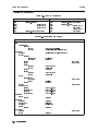
8. Specications
Specications . . . . . . . . . .
Measurement Parameters . . . .
Measurement Conditions . . . .
DC Test Voltage (Vs) . . . . .
Ammeter . . . . . . . . . .
Test Cable Length . . . . . .
Measurement Time Mode . . .
Ranging . . . . . . . . . . .
Averaging . . . . . . . . . .
Trigger Mode . . . . . . . .
Trigger Delay Time . . . . .
Measurement Range . . . . . .
Measurement Accuracy . . . .
Measurement Support Functions
Contents-8
.
.
.
.
.
.
.
.
.
.
.
.
.
.
.
.
.
.
.
.
.
.
.
.
.
.
.
.
.
.
.
.
.
.
.
.
.
.
.
.
.
.
.
.
.
.
.
.
.
.
.
.
.
.
.
.
.
.
.
.
.
.
.
.
.
.
.
.
.
.
.
.
.
.
.
.
.
.
.
.
.
.
.
.
.
.
.
.
.
.
.
.
.
.
.
.
.
.
.
.
.
.
.
.
.
.
.
.
.
.
.
.
.
.
.
.
.
.
.
.
.
.
.
.
.
.
.
.
.
.
.
.
.
.
.
.
.
.
.
.
.
.
.
.
.
.
.
.
.
.
.
.
.
.
.
.
.
.
.
.
.
.
.
.
.
.
.
.
.
.
.
.
.
.
.
.
.
.
.
.
.
.
.
.
.
.
.
.
.
.
.
.
.
.
.
.
.
.
.
.
.
.
.
.
.
.
.
.
.
.
.
.
.
.
.
.
.
.
.
.
.
.
.
.
.
.
.
.
.
.
.
.
.
.
.
.
.
.
.
.
.
.
.
.
.
.
.
.
.
.
.
.
.
.
.
.
.
.
.
.
.
.
.
.
.
.
.
.
.
.
.
.
.
.
.
.
.
.
.
.
.
.
.
.
.
.
.
.
.
.
.
.
.
.
.
.
.
.
.
.
.
.
.
.
.
.
.
.
.
.
.
.
.
.
.
.
.
8-2
8-2
8-2
8-2
8-2
8-2
8-2
8-2
8-2
8-3
8-3
8-3
8-4
8-6
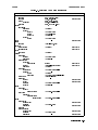
Display . . . . . . . . . . . . . . . . . . .
Correction . . . . . . . . . . . . . . . . . .
Test Sequence Program: . . . . . . . . . . .
Mathematical Functions . . . . . . . . . . .
Comparator . . . . . . . . . . . . . . . . .
Contact Check . . . . . . . . . . . . . . . .
GPIB Interface . . . . . . . . . . . . . . .
Handler Interface . . . . . . . . . . . . . .
Save/Recall . . . . . . . . . . . . . . . . .
Continuous Memory Capability . . . . . . . .
Key Lock . . . . . . . . . . . . . . . . . .
General . . . . . . . . . . . . . . . . . . . .
Power Requirements . . . . . . . . . . . . .
Operating Temperature, Humidity, and Altitude
Storage Temperature, Humidity, and Altitude .
EMC . . . . . . . . . . . . . . . . . . . .
Safety . . . . . . . . . . . . . . . . . . . .
Dimensions . . . . . . . . . . . . . . . . .
Weight . . . . . . . . . . . . . . . . . . .
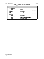
Supplemental Performance Characteristics . . . .
Typical Measurement Accuracy . . . . . . . . .
Measurement Time . . . . . . . . . . . . . . .
DC Test Voltage Settling . . . . . . . . . . . .
DC Test Voltage Output Resistance . . . . . . .
Continuous Memory Duration . . . . . . . . . .
.
.
.
.
.
.
.
.
.
.
.
.
.
.
.
.
.
.
.
.
.
.
.
.
.
.
.
.
.
.
.
.
.
.
.
.
.
.
.
.
.
.
.
.
.
.
.
.
.
.
.
.
.
.
.
.
.
.
.
.
.
.
.
.
.
.
.
.
.
.
.
.
.
.
.
.
.
.
.
.
.
.
.
.
.
.
.
.
.
.
.
.
.
.
.
.
.
.
.
.
.
.
.
.
.
.
.
.
.
.
.
.
.
.
.
.
.
.
.
.
.
.
.
.
.
.
.
.
.
.
.
.
.
.
.
.
.
.
.
.
.
.
.
.
.
.
.
.
.
.
.
.
.
.
.
.
.
.
.
.
.
.
.
.
.
.
.
.
.
.
.
.
.
.
.
.
.
.
.
.
.
.
.
.
.
.
.
.
.
.
.
.
.
.
.
.
.
.
.
.
.
.
.
.
.
.
.
.
.
.
.
.
.
.
.
.
.
.
.
.
.
.
.
.
.
.
.
.
.
.
.
.
.
.
.
.
.
.
.
.
.
.
.
.
.
.
.
.
.
.
.
.
.
.
.
.
.
.
.
.
.
.
.
.
.
.
.
.
.
.
.
.
.
.
.
.
.
.
.
.
.
.
.
.
.
.
.
.
.
.
.
.
.
.
.
.
.
.
.
.
.
.
.
.
.
.
.
.
.
.
.
.
.
.
.
.
.
.
.
.
.
.
.
.
.
.
.
.
.
.
.
.
.
.
.
.
.
.
.
.
.
.
.
.
.
.
.
.
.
.
8-6
8-6
8-6
8-6
8-6
8-6
8-6
8-6
8-6
8-7
8-7
8-7
8-7
8-7
8-7
8-7
8-7
8-7
8-7
8-8
8-8
8-8
8-9
8-9
8-9
.
.
.
.
.
.
.
.
.
.
.
.
.
.
.
.
.
.
.
.
.
.
.
.
.
.
.
.
.
.
.
.
.
.
.
.
.
.
.
.
.
.
.
.
.
.
.
.
.
.
.
.
.
.
.
.
.
.
.
.
.
.
.
.
.
.
.
.
.
.
.
.
.
.
.
.
.
.
.
.
.
.
.
.
.
.
.
.
.
.
.
.
.
.
.
.
.
.
.
.
.
.
.
.
.
.
.
.
.
.
.
.
.
.
.
.
.
.
.
.
9-1
9-1
9-2
9-2
9-2
9-2
9-3
9-3
Source Voltage Accuracy Test . . . . . . .
Specication . . . . . . . . . . . . . . . . .
Test Equipment . . . . . . . . . . . . . . .
Procedure . . . . . . . . . . . . . . . . . .
Ammeter Oset Voltage and Input Resistance Test
Specication . . . . . . . . . . . . . . . . .
Test Equipment . . . . . . . . . . . . . . .
Procedure . . . . . . . . . . . . . . . . . .
Ammeter Oset Voltage Test . . . . . . . .
Ammeter Input Resistance Test . . . . . . .
Current Measurement Accuracy Test . . . . . .
Specication . . . . . . . . . . . . . . . . .
Test Equipment . . . . . . . . . . . . . . .
Procedure . . . . . . . . . . . . . . . . . .
Resistance Measurement Accuracy Test . .
Specication . . . . . . . . . . . . . . . . .
Test Equipment . . . . . . . . . . . . . . .
Procedure . . . . . . . . . . . . . . . . . .
.
.
.
.
.
.
.
.
.
.
.
.
.
.
.
.
.
.
.
.
.
.
.
.
.
.
.
.
.
.
.
.
.
.
.
.
.
.
.
.
.
.
.
.
.
.
.
.
.
.
.
.
.
.
.
.
.
.
.
.
.
.
.
.
.
.
.
.
.
.
.
.
.
.
.
.
.
.
.
.
.
.
.
.
.
.
.
.
.
.
.
.
.
.
.
.
.
.
.
.
.
.
.
.
.
.
.
.
.
.
.
.
.
.
.
.
.
.
.
.
.
.
.
.
.
.
.
.
.
.
.
.
.
.
.
.
.
.
.
.
.
.
.
.
.
.
.
.
.
.
.
.
.
.
.
.
.
.
.
.
.
.
.
.
.
.
.
.
.
.
.
.
.
.
.
.
.
.
.
.
.
.
.
.
.
.
.
.
.
.
.
.
.
.
.
.
.
.
.
.
.
.
.
.
.
.
.
.
.
.
.
.
.
.
.
.
.
.
.
.
.
.
.
.
.
.
.
.
.
.
.
.
.
.
.
.
.
.
.
.
.
.
.
.
.
.
.
.
.
.
.
.
9-4
9-4
9-4
9-4
9-6
9-6
9-6
9-6
9-6
9-7
9-8
9-8
9-8
9-8
9-12
9-12
9-12
9-12
9. Maintenance
Introduction . . . . . . .
Test Equipment . . . . .
Performance Tests . . . .
Introduction . . . . . .
Test Equipment . . . .
Calculation Sheet . . .
Performance Test Record
Calibration Cycle . . .
.
.
.
.
.
.
.
.
.
.
.
.
.
.
.
.
.
.
.
.
.
.
.
.
.
.
.
.
.
.
.
.
.
.
.
.
.
.
.
.
.
.
.
.
.
.
.
.
.
.
.
.
.
.
.
.
.
.
.
.
.
.
.
.
.
.
.
.
.
.
.
.
.
.
.
.
.
.
.
.
.
.
.
.
.
.
.
.
Contents-9
Resistance Measurement Accuracy Test (Floating Device) .
Resistance Measurement Accuracy Test (Grounded Device)
Calculation Sheet . . . . . . . . . . . . . . . . . . . . .
Source Voltage Accuracy Test . . . . . . . . . . . . . . .
Ammeter Input Resistance Test . . . . . . . . . . . . . .
RC Box Calibration Values . . . . . . . . . . . . . . . .
Current Measurement Accuracy Test . . . . . . . . . . .
Resistance Measurement Accuracy Test . . . . . . . . . .
Performance Test Record . . . . . . . . . . . . . . . . . .
Source Voltage Accuracy Test . . . . . . . . . . . . . . .
Ammeter Oset Voltage and Input Resistance Test . . . . .
Current Measurement Accuracy Test . . . . . . . . . . .
Resistance Measurement Accuracy Test . . . . . . . . . .
Functional Test . . . . . . . . . . . . . . . . . . . . . . .
Introduction . . . . . . . . . . . . . . . . . . . . . . . .
Test Equipment . . . . . . . . . . . . . . . . . . . . . .
Handler Interface Functional Test . . . . . . . . . . . . . .
Test Equipment . . . . . . . . . . . . . . . . . . . . .
Procedure . . . . . . . . . . . . . . . . . . . . . . . .
Initial Setup . . . . . . . . . . . . . . . . . . . . . .
Key Lock Function Test . . . . . . . . . . . . . . . .
External Trigger Function Test . . . . . . . . . . . . .
Handler Interface Output Test . . . . . . . . . . . . .
Contact Check Functional Test . . . . . . . . . . . . . . .
Test Equipment . . . . . . . . . . . . . . . . . . . . .
Procedure . . . . . . . . . . . . . . . . . . . . . . . .
A. Manual Changes
Introduction . .
Manual Changes
Serial Number .
Change 1 . . .
Change 2 . . .
.
.
.
.
.
.
.
.
.
.
.
.
.
.
.
.
.
.
.
.
.
.
.
.
.
.
.
.
.
.
.
.
.
.
.
.
.
.
.
.
.
.
.
.
.
.
.
.
.
.
.
.
.
.
.
.
.
.
.
.
.
.
.
.
.
.
.
.
.
.
.
.
.
.
.
.
.
.
.
.
.
.
.
.
.
.
.
.
.
.
.
.
.
.
.
.
.
.
.
.
.
.
.
.
.
.
.
.
.
.
.
.
.
.
.
.
.
.
.
.
.
.
.
.
.
.
.
.
.
.
.
.
.
.
.
.
.
.
.
.
.
.
.
.
.
.
.
.
.
.
.
.
.
.
.
.
.
.
.
.
.
.
.
.
.
.
.
.
.
.
.
.
.
.
.
.
.
.
.
.
.
.
.
.
.
.
.
.
.
.
.
.
.
.
.
.
.
.
.
.
.
.
.
.
.
.
.
.
.
.
.
.
.
.
.
.
.
.
.
.
.
.
.
.
.
.
.
.
.
.
.
.
.
.
.
.
.
.
.
.
.
.
.
.
.
.
.
.
.
.
.
.
.
.
.
.
.
.
9-12
9-15
9-17
9-17
9-17
9-17
9-18
9-18
9-19
9-19
9-19
9-20
9-20
9-21
9-21
9-21
9-22
9-22
9-22
9-22
9-22
9-22
9-23
9-24
9-24
9-24
.
.
.
.
.
.
.
.
.
.
.
.
.
.
.
.
.
.
.
.
.
.
.
.
.
.
.
.
.
.
.
.
.
.
.
.
.
.
.
.
.
.
.
.
.
.
.
.
.
.
.
.
.
.
.
.
.
.
.
.
.
.
.
.
.
.
.
.
.
.
.
.
.
.
.
.
.
.
.
.
.
.
.
.
.
.
.
.
.
.
.
.
.
.
.
.
.
.
.
.
.
.
.
.
.
A-1
A-1
A-2
A-3
A-3
Electrical Characteristics . . . . . . .
Output Signals . . . . . . . . . . .
Input Signals . . . . . . . . . . .
Setting Up the Handler Interface Board
Tools and Fasteners . . . . . . . . .
Procedure . . . . . . . . . . . . . .
.
.
.
.
.
.
.
.
.
.
.
.
.
.
.
.
.
.
.
.
.
.
.
.
.
.
.
.
.
.
.
.
.
.
.
.
.
.
.
.
.
.
.
.
.
.
.
.
.
.
.
.
.
.
.
.
.
.
.
.
.
.
.
.
.
.
.
.
.
.
.
.
.
.
.
.
.
.
.
.
.
.
.
.
.
.
.
.
.
.
.
.
.
.
.
.
.
.
.
.
.
.
.
.
.
.
.
.
.
.
.
.
.
.
.
.
.
.
.
.
B-1
B-1
B-4
B-5
B-5
B-5
.
.
.
.
.
.
.
.
.
.
.
.
.
.
.
.
.
.
.
.
.
.
.
.
.
.
.
.
.
.
.
.
.
.
.
.
.
.
.
.
.
.
.
.
.
.
.
.
.
.
.
.
.Messages-2
.
.Messages-2
.
.Messages-2
.
.Messages-4
.
B. Handler Interface Installation
C. Overload/Over-Current/No-Contact Operations
Messages
Out of Range . .
Warning . . . . .
Instrument Errors
GPIB Errors . . .
Index
Contents-10
.
.
.
.
.
.
.
.
.
.
.
.
.
.
.
.
.
.
.
.
.
.
.
.
.
.
.
.
.
.
.
.
.
.
.
.
.
.
.
.
.
.
.
.
.
.
.
.
.
.
.
.
.
.
.
.
.
.
.
.
Figures
1-1.
1-2.
1-3.
3-1.
3-2.
3-3.
3-4.
3-5.
3-6.
3-7.
3-8.
3-9.
3-10.
4-1.
4-2.
4-3.
4-4.
4-5.
4-6.
4-7.
4-8.
5-1.
5-2.
5-3.
5-4.
5-5.
5-6.
5-7.
5-8.
5-9.
5-10.
5-11.
5-12.
6-1.
6-2.
6-3.
6-4.
6-5.
6-6.
6-7.
7-1.
7-2.
7-3.
9-1.
Power Cable Supplied . . . . . . . . . . . . . . . . . . . . . . . . . . .
Floating DUT Measurement Conguration . . . . . . . . . . . . . . . . . .
Grounded DUT Measurement Conguration . . . . . . . . . . . . . . . . .
Front Panel . . . . . . . . . . . . . . . . . . . . . . . . . . . . . . . .
Sequence Mode . . . . . . . . . . . . . . . . . . . . . . . . . . . . . .
Oset-Error Canceling Timing Chart . . . . . . . . . . . . . . . . . . . .
Rear Panel . . . . . . . . . . . . . . . . . . . . . . . . . . . . . . . .
Required External Trigger Pulse Specication . . . . . . . . . . . . . . . .
Pin Assignment for Handler Interface Connector . . . . . . . . . . . . . . .
Timing Diagram . . . . . . . . . . . . . . . . . . . . . . . . . . . . . .
Simplied Model of Impedance Measurement . . . . . . . . . . . . . . . .
4339B Overall Block Diagram . . . . . . . . . . . . . . . . . . . . . . . .
Ungrounded and Grounded DUT Measurement . . . . . . . . . . . . . . .
Simple Program Example . . . . . . . . . . . . . . . . . . . . . . . . . .
SRQ generation sequence (when measurement nishes) . . . . . . . . . . .
Detecting the completion of measurement using SRQ . . . . . . . . . . . . .
Reading out the measured result in ASCII transfer format by using the *TRG
command . . . . . . . . . . . . . . . . . . . . . . . . . . . . . . .
Reading out the measured result in binary transfer format using *TRG command
Reading out the measured result in ASCII transfer format using the :FETC?
command . . . . . . . . . . . . . . . . . . . . . . . . . . . . . . .
Reading out measured result in binary transfer format using :FETC? command
Sample Program . . . . . . . . . . . . . . . . . . . . . . . . . . . . . .
Proper Use of the Colon and Semicolon . . . . . . . . . . . . . . . . . . .
Status Reporting Structure . . . . . . . . . . . . . . . . . . . . . . . . .
Status byte Register . . . . . . . . . . . . . . . . . . . . . . . . . . . .
Standard Event Status Register . . . . . . . . . . . . . . . . . . . . . . .
Standard Operation Status Group Structure . . . . . . . . . . . . . . . . .
Trigger System Conguration . . . . . . . . . . . . . . . . . . . . . . . .
Inside an ARM Event Detection State . . . . . . . . . . . . . . . . . . . .
Inside a TRIG Event Detection State . . . . . . . . . . . . . . . . . . . .
NR1 Format . . . . . . . . . . . . . . . . . . . . . . . . . . . . . . . .
NR2 Format . . . . . . . . . . . . . . . . . . . . . . . . . . . . . . . .
NR3 Format . . . . . . . . . . . . . . . . . . . . . . . . . . . . . . . .
Real Data Format . . . . . . . . . . . . . . . . . . . . . . . . . . . . .
Measurement Conguration . . . . . . . . . . . . . . . . . . . . . . . .
Chip Capacitor Binding . . . . . . . . . . . . . . . . . . . . . . . . . . .
Measurement Conguration . . . . . . . . . . . . . . . . . . . . . . . .
Resistivity Cell Setup . . . . . . . . . . . . . . . . . . . . . . . . . . .
Measurement Conguration . . . . . . . . . . . . . . . . . . . . . . . .
Clipping Opened Switch . . . . . . . . . . . . . . . . . . . . . . . . . .
Printed Results . . . . . . . . . . . . . . . . . . . . . . . . . . . . . .
Volume Resistivity . . . . . . . . . . . . . . . . . . . . . . . . . . . . .
Surface Resistivity . . . . . . . . . . . . . . . . . . . . . . . . . . . . .
Capacitance Measurement Conguration . . . . . . . . . . . . . . . . . .
Source Voltage Accuracy Test Setup . . . . . . . . . . . . . . . . . . . . .
1-11
1-19
1-19
3-2
3-6
3-18
3-20
3-20
3-22
3-24
3-26
3-27
3-28
4-4
4-12
4-13
4-16
4-18
4-20
4-22
4-29
5-2
5-40
5-41
5-42
5-43
5-45
5-46
5-47
5-48
5-48
5-48
5-49
6-2
6-3
6-5
6-6
6-9
6-10
6-11
7-3
7-4
7-7
9-4
Contents-11
9-2.
9-3.
9-4.
9-5.
9-6.
9-7.
9-8.
9-9.
9-10.
9-11.
9-12.
9-13.
9-14.
A-1.
B-1.
B-2.
B-3.
B-4.
B-5.
Ammeter Oset Voltage Test Setup . . . . . . . . . . .
RC Box Connection . . . . . . . . . . . . . . . . . .
Current Measurement Accuracy Test Setup . . . . . . .
RC Box Connection . . . . . . . . . . . . . . . . . .
Resistance Measurement Accuracy Test Setup (Floating) .
RC Box Connection (Floating) . . . . . . . . . . . . . .
RC Box Connection for 1011 Resistor . . . . . . . . .
Resistance Measurement Accuracy Test Setup (Grounded)
RC Box Connection (Grounded) . . . . . . . . . . . . .
Handler Interface Functional Test Setup . . . . . . . . .
Handler Interface Output Order . . . . . . . . . . . .
Contact Check Functional Test Setup . . . . . . . . . .
Contact Check Functional Test Setup . . . . . . . . . .
Serial Number Plate . . . . . . . . . . . . . . . . . .
Handler Interface Comparison Output Signals Diagram . .
Handler Interface Control Output Signals Diagram . . . .
Handler Interface Input Signal Diagram . . . . . . . . .
Top View of 4339B with Cover Removed . . . . . . . .
A1 Main Board . . . . . . . . . . . . . . . . . . . .
Contents-12
.
.
.
.
.
.
.
.
.
.
.
.
.
.
.
.
.
.
.
.
.
.
.
.
.
.
.
.
.
.
.
.
.
.
.
.
.
.
.
.
.
.
.
.
.
.
.
.
.
.
.
.
.
.
.
.
.
.
.
.
.
.
.
.
.
.
.
.
.
.
.
.
.
.
.
.
.
.
.
.
.
.
.
.
.
.
.
.
.
.
.
.
.
.
.
.
.
.
.
.
.
.
.
.
.
.
.
.
.
.
.
.
.
.
.
.
.
.
.
.
.
.
.
.
.
.
.
.
.
.
.
.
.
.
.
.
.
.
.
.
.
.
.
.
.
.
.
.
.
.
.
.
.
.
.
.
.
.
.
.
.
.
.
.
.
.
.
.
.
.
.
.
.
.
.
.
.
.
.
.
.
.
.
.
.
.
.
.
.
.
9-6
9-7
9-9
9-10
9-13
9-14
9-14
9-15
9-16
9-22
9-23
9-24
9-25
A-2
B-2
B-3
B-4
B-6
B-8
Tables
1-1.
2-1.
2-2.
3-1.
3-2.
3-3.
3-4.
3-5.
5-1.
5-2.
5-3.
5-4.
5-5.
5-6.
5-7.
7-1.
7-2.
7-3.
8-1.
9-1.
9-2.
9-3.
9-4.
9-5.
A-1.
A-2.
A-3.
A-4.
B-1.
B-2.
B-3.
C-1.
C-2.
Power Voltage Selector Setting . . . . . . . . . . . . . .
Value a . . . . . . . . . . . . . . . . . . . . . . . . .
Value b . . . . . . . . . . . . . . . . . . . . . . . . .
Interlock Condition for 16008B and 16339A . . . . . . . .
Interlock Condition for 16117B Low Noise Test Leads . . .
Reset Settings . . . . . . . . . . . . . . . . . . . . . .
Contact Assignment for Comparator Function . . . . . . .
GPIB Interface Capability . . . . . . . . . . . . . . . .
Selection of ARM Source and Trigger Source . . . . . . . .
Status Byte Assignments . . . . . . . . . . . . . . . . .
Standard Event Status Register Assignments . . . . . . . .
Operation Status Condition Register Assignments . . . . .
Operation Status Event Register Assignments . . . . . . .
Common Commands . . . . . . . . . . . . . . . . . . .
Subsystem Commands . . . . . . . . . . . . . . . . . .
Maximum Measurable Capacitance . . . . . . . . . . . .
Limit Output Resistance for Each Range . . . . . . . . . .
Appropriate Output Resistance for Range . . . . . . . . .
Measurement Accuracy . . . . . . . . . . . . . . . . .
Required Equipment . . . . . . . . . . . . . . . . . . .
Source Voltage Accuracy Test Settings . . . . . . . . . . .
Current Measurement Accuracy Test Settings . . . . . . .
Resistance Measurement Accuracy Test Settings . . . . . .
Resistance Measurement Accuracy Test Settings (Grounded)
Manual Changes by Serial Number . . . . . . . . . . . .
Manual Changes by ROM Version . . . . . . . . . . . . .
OVLD/Over-Current/N.C. Operations (Meas. parameter: R) .
OVLD/Over-Current/N.C. Operations(Meas. parameter: I) . .
Handler Output Electrical Characteristics . . . . . . . . .
Handler Input Electrical Characteristics . . . . . . . . . .
Pull-up Resistor Location . . . . . . . . . . . . . . . . .
OVLD/Over-Current/N.C. Operations (Meas. parameter: R) .
OVLD/Over-Current/N.C. Operations(Meas. parameter: I) . .
.
.
.
.
.
.
.
.
.
.
.
.
.
.
.
.
.
.
.
.
.
.
.
.
.
.
.
.
.
.
.
.
.
.
.
.
.
.
.
.
.
.
.
.
.
.
.
.
.
.
.
.
.
.
.
.
.
.
.
.
.
.
.
.
.
.
.
.
.
.
.
.
.
.
.
.
.
.
.
.
.
.
.
.
.
.
.
.
.
.
.
.
.
.
.
.
.
.
.
.
.
.
.
.
.
.
.
.
.
.
.
.
.
.
.
.
.
.
.
.
.
.
.
.
.
.
.
.
.
.
.
.
.
.
.
.
.
.
.
.
.
.
.
.
.
.
.
.
.
.
.
.
.
.
.
.
.
.
.
.
.
.
.
.
.
.
.
.
.
.
.
.
.
.
.
.
.
.
.
.
.
.
.
.
.
.
.
.
.
.
.
.
.
.
.
.
.
.
.
.
.
.
.
.
.
.
.
.
.
.
.
.
.
.
.
.
.
.
.
.
.
.
.
.
.
.
.
.
.
.
.
.
.
.
.
.
.
.
.
.
.
.
.
.
.
.
.
.
.
.
.
.
.
.
.
.
.
.
.
.
.
.
.
.
.
.
.
.
.
.
.
.
.
.
.
.
.
.
.
.
.
.
.
.
.
.
.
.
.
.
.
.
.
.
.
.
.
1-12
2-12
2-13
3-3
3-3
3-17
3-23
3-25
5-35
5-41
5-42
5-44
5-44
5-50
5-50
7-5
7-5
7-6
8-4
9-1
9-5
9-11
9-15
9-16
A-1
A-1
A-3
A-4
B-1
B-4
B-9
C-1
C-2
Contents-13
1
Getting Started
Introduction
This chapter provides information to get you started using your 4339B High Resistance Meter.
This chapter discusses the following topics:
Overview
Initial Inspection
Ventilation Requirements
Instruction for Cleaning
Power Cable
Preparation for Use
Using the Front-Panel Keys
Basic Operation
Getting Started 1-1
Overview
4339B
Overview
The 4339B High Resistance Meter is designed for measuring very high resistance and related
parameters of insulation materials, electronic components, and electro-mechanical components.
Features
Measurement Parameters:
Resistance (R)
Volume Resistivity (%v )
Surface Resistivity (%s )
Current (I)
Test Voltage : 0.1 to 1000 Vdc
R Measurement Range: 103 to 1.621016 Basic Accuracy: 0.6 %
High speed contact check
Built-in comparator
Interface: GPIB and handler interfaces
The 4339B's measurement range is from 1.02103 to 1.621016 . This wide range allows
accurate high resistance measurements of capacitors, relays, switches, connectors, materials,
cables, and PC boards.
The 4339B has the capability to measure grounded DUTs (Device Under Test), which is gives
you the ability to measure and evaluate devices such as PC board patterns.
The 16008B resistivity cell and the 16339A component test xture are designed for stable and
safe measurements of materials or components.
The Measurement Sequence Program function allows you to control a series of resistance
measurements in a sequence (charge-measure-discharge). You can set the charge time,
measurement interval time, and the number of measurements in a sequence from the front
panel.
Surface resistivity (s) and volume resistivity (v) are calculated automatically and the result is
displayed.
1-2 Getting Started
4339B
Overview
Accessories Available
The following accessories are available for the 4339B:
16339A
Component Test Fixture: For lead, chip, or other types of components.
16008B
Resistivity Cell: For resistivity measurement of solid sheet materials. Two
optional electrode sizes can be ordered in addition to the installed standard 50
mm diameter electrode.
Option 001: Add 26/78mm diameter electrodes
Option 002: Add 26mm diameter electrode
Option 003: Add 78mm diameter electrode
16117B
Low Noise Test Leads (1 m) : Alligator clip leads.
16117C
Low Noise Test Leads (1 m) : A Set of male-male triaxial and BNC cables,
and an interlock cable. Female-triaxial and Female BNC connectors are also
included.
16118A
Tweezer Test Fixture: For chip components.
16064B
LED display/trigger box : Displays comparator status and allows manual
triggering.
Getting Started 1-3
Overview
4339B
Front Panel
This section gives a guided tour of the front panel. For a detailed description of each key's
function, refer to Chapter 3.
Each description starting with (Shift) is the secondary function of the key, which is available by
pressing the blue shift key (refer to \Shift Key").
1. Display displays measurement results, instrument states, and error messages.
2. LINE Switch turns the 4339B ON and OFF.
3. Interlock Connector provides safety from high voltages and identies which test xture is
connected.
4. UNKNOWN Terminal is the connection port of the test xture.
5. High Voltage Indicator indicates that the 4339B is outputting dangerous voltage levels up
to 1000 Vdc.
6. Voltage Output Key applies test voltage to DUT.
7. Voltage Output Indicator indicates when voltage is applied at Output terminal.
8. Measurement Parameter Key selects the measurement parameter.
(Shift) Electrode Size Key denes the size of the test xture electrode.
9. Show Setting Key selects the mode of the Measurement Settings display on the right side
of the LCD display.
(Shift) Current Monitor Key sets the current monitor.
10. Auto/Hold Key toggles the measurement range mode between Auto and Hold.
(Shift) Range Setup Key selects the measurement range.
11. Left/Down and Right/Up Arrow Keys increases or decreases the setting value.
12. Source Voltage Key sets the value of the applied voltage.
(Shift) Current Limit Key sets the limit value of the current through the DUT.
13. Measurement Time Key selects measurement time mode of Short, Medium, or Long.
(Shift) Average key sets the averaging rate.
14. Measurement Sequence Mode Key selects the measurement sequence mode.
(Shift) Program Key sets the measurement sequence.
1-4 Getting Started
4339B
Overview
15. Trigger Mode Key selects the trigger source from Internal, Manual, or External.
(Shift) Delay Key sets the trigger delay time.
16. Trigger Key triggers a measurement in the Manual trigger mode.
(Shift) Sequence Abort Key cancels a measurement sequence.
17. Local Key cancels the GPIB remote state.
(Shift) Address Key sets the GPIB address.
18. Recall Key recalls instrument state data from the internal memory.
(Shift) Save Key stores instrument state data to the internal memory.
19. High Limit Key sets the upper limit value for the comparator function.
20. Low Limit Key sets the lower limit values for the comparator function.
21. Entry Keys
7 Key / (Shift) Minimum Key inputs the minimum value for
a setting operation.
8 Key / (Shift) Maximum Key enters the maximum value for
a setting operation.
9 Key
Shift Key activates the secondary functions printed above
the front-panel keys.
Note
In this manual, the blue Shift key is expressed as
the key is not labeled with the word \blue".
, even though the top of
4 Key / (Shift) Open Key executes an OPEN correction.
5 Key / (Shift) Calibration Key executes the calibration function.
6 Key / (Shift) 1 Mode Key selects the deviation measurement mode, and sets the
nominal value used in the deviaiton measurement.
Exponential Key allows input of exponent value.
1 Key / (Shift) Comprtr Key toggles the comparator function ON or OFF.
2 Key / (Shift) Contact Check Key toggles the contact check function ON or OFF.
3 Key / (Shift) Display Mode Key selects the display mode and display format.
Back Space Key erases the last character entered.
0 Key / (Shift) Key Lock Key toggles to disable and enable the front panel key input.
. (point) Key / (Shift) Reset Key resets the 4339B to its default state.
0 (minus) Key / (Shift) Conguration Key sets the oset-error canceling, beeper setting,
and the power line frequency, and executes the internal test.
Enter Key enters the input value to the
4339B.
Getting Started 1-5
Overview
4339B
Display
This section gives a guided tour of the display panel. For more detailed description of each
item, refer to Chapter 3.
1. Measurement Result Display Area displays measurement result and instrument messages.
2. Measurement Setting Display Area displays instrument settings.
3. Annunciator indicates other instrument settings. Annunciator labels are as follows:
a. Sequence Running indicates a measurement sequence is running.
b. Measurement Time shows measurement time Short, Medium, or Long.
c. Trigger indicates trigger mode is Internal (Int), Manual (Man), or External (Ext).
d. Hold Range indicates measurement range is in hold mode. In Auto mode ,the
annunciator is not displayed.
e. Comparator On indicates the comparator function is ON.
f. Contact Check On indicates the contact check function is ON.
g. Talk Only indicates the GPIB state is Talk Only.
h. Remote indicates the GPIB state is remote.
i. Key Lock indicates the 4339B's front-panel keys are disabled.
j. Shift indicates that the shift toggle is activated.
1-6 Getting Started
4339B
Overview
Rear Panel
This section gives a tour of the rear panel. For a more detailed description of each item, refer
to Chapter 3.
1. GPIB Interface is used for controlling the 4339B from an external controller using GPIB
commands.
2. Handler Interface is used to synchronize timing with an external handler.
3. Ext Trigger Terminal is used to trigger a measurement using an external signal.
4. Serial Number Plate gives the instrument's manufacturing information.
5. Line Voltage Selector Switch is used to set the voltage to that of the AC power source.
6. Line Fuse Holder
7. Power Cord Receptacle
Getting Started 1-7
Initial Inspection
4339B
Initial Inspection
Warning
To avoid hazardous electrical shock, do not turn on the 4339B when there
are signs of shipping damage to any portion of the outer enclosure (for
example, covers, panel, or display)
Inspect the shipping container for damage. If the shipping container or cushioning material
is damaged, it should be kept until the contents of the shipment have been checked for
completeness and the 4339B has been checked mechanically and electrically. The contents of
the shipment should be as follows:
4339B High Resistance Meter
Power cable
Shunt connector
The Agilent part number is 04339-60003
Operation Manual (Option ABA, This book)
User's Guide
CD-ROM (Manual)
If the contents are incomplete, if there is mechanical damage or defect, or if the analyzer does
not pass the power-on selftests, notify the nearest Agilent Technologies oce. If the shipping
container is damaged, or the cushioning material shows signs of unusual stress, notify the
carrier as well as the Agilent Technologies oce. Keep the shipping materials for the carrier's
inspection.
Providing clearance to dissipate heat at installation site
To ensure the specications and measurement accuracy of the product, you must keep ambient
temperature around the product within the specied range by providing appropriate cooling
clearance around the product or, for the rackmount type, by forcefully air-cooling inside
the rack housing. For information on ambient temperature to satisfy the specications and
measurement accuracy of the product, refer to Chapter 8, Specications.
When the ambient temperature around the product is kept within the temperature range of the
operating environment specication (refer to \General" in Chapter 8), the product conforms to
the requirements of the safety standard. Furthermore, under that temperature environment, it
has been conrmed that the product still conforms to the requirements of the safety standard
when it is enclosed with cooling clearance as follows:
Conditions
1-8 Getting Started
Rear
250 mm
Side
100 mm
4339B
Initial Inspection
Instruction for Cleaning
For cleaning, wipe with soft cloth that is soaked with water and wrung tightly without undue
pressure.
Getting Started 1-9
Initial Inspection
4339B
Power Cable
In accordance with international safety standards, this instrument is equipped with a
three-wire power cable. When connected to an appropriate ac power outlet, this cable grounds
the instrument frame. The type of power cable shipped with each instrument depends on the
country of destination. Refer to Figure 1-1 for the part numbers of the power cables available.
Warning
For protection from electrical shock, the power cable ground must not be
defeated. The power plug must be plugged into an outlet that provides a
protective earth ground connection.
1-10 Getting Started
4339B
Initial Inspection
Figure 1-1. Power Cable Supplied
Getting Started 1-11
Preparation for Use
4339B
Preparation for Use
Before you use the 4339B, you must set it to match the available power line voltage and
frequency.
Set power line voltage|refer to \Power Requirements".
Set power line frequency|refer to \
Turning ON the 4339B"
Power Requirements
The 4339B requires a following power source:
Line Voltage : 100 / 120 / 220 / 240 V ac (610%)
Line Frequency : 47 to 66 Hz
Power Consumption : 45 VA maximum
Conrm that the LINE Voltage Selector on the rear panel is set to match the power line voltage
before plugging in the 4339B. Refer to Table 1-1.
Table 1-1. Power Voltage Selector Setting
Voltage Selector
Line Voltage
100V/120Vac(610%)
220V/240Vac(610%)
Required Fuse
UL/CSA type, Time delay 0.5A 250V
(Agilent part number 2110-0202)
UL/CSA type, Time delay 0.25A 250V
(Agilent part number 2110-0201)
To change the LINE voltage setting of the 4339B:
1. Conrm power cable is disconnected.
2. Slide the LINE Voltage selector on the rear panel to match the ac line voltage. (refer to
Table 1-1.)
Fuse
Use the fuse shown in Table 1-1. If you require the fuse, contact the nearest Agilent
Technologies sales oce.
The fuse can be replaced by turning the fuse holder counterclockwise until the fuse holder
pops out with a minus screw driver. For the fuse holder location, see \Rear Panel" in this
chapter.
1-12 Getting Started
4339B
Preparation for Use
Turning ON the 4339B
1. Connect the power cable to Power Cord Receptacle on the rear panel.
2. Push the LINE switch in. The 4339B will emit a beep and start the self test.
(If any message is displayed, refer to the \Messages" in the back of this manual.) The 4339B
will be ready for operation after a message similar to the one shown in the following gure
is displayed.
3. When you turn on the 4339B for the rst time, conrm the power line frequency is set
correctly.
a. Press
. The following menu is displayed.
b. Press
until more blinks, and press
.
c. Press
until Line blinks, and press
.
A blinking item means that it is currently selected.
d. If the setting does not match the power line frequency, press
between 50 Hz and 60 Hz. Then press
.
e. Press
until Exit blinks, and press
to toggle the setting
to exit this menu.
The power line frequency setting is stored and is not changed after reset or power-o. Once
you set it, you do not need to set the line frequency again as long as the same power line
frequency is being used.
Getting Started 1-13
Preparation for Use
Power-On Self Test
4339B
When turned on, the 4339B performs self test which checks basic operation of the analog
and digital circuits, display, LED, and Beeper. If an error is detected, an error message will
be displayed on the LCD. For more information, refer to \Conguration Key
" in
Chapter 3.
Warning
Before turning the 4339B OFF, the High Voltage indicator must be OFF.
When the High Voltage indicator is ON, wait until the High Voltage
indicator is OFF. (When both the High Voltage indicator and the V Output
indicator are ON, turn OFF the V Output rst by pressing
.)
1-14 Getting Started
4339B
Using Front Panel Keys
Using Front Panel Keys
The 4339B has three types of keys as follows:
Direct Execution Type Keys
Toggle Type Keys
Selection Type Keys
Value Setup Type Keys
Note
If you want to exit an operation and go back to the measurement mode, press
several times until you are back to the measurement mode.
Direct Execution Type Keys
Pressing a direct execution key performs the pressed key's function immediately. For example,
press
and the 4339B's front panel keys are locked out immediately.
Toggle Type Keys
Pressing a toggle type key will switch the setting. An annunciator( 9 ) indicates the current
setting. For example,
Press
and the Meas Time annunciator( 9 ) moves to the next measurement time mode.
Selection Type Keys
Pressing a selection type key will display a menu or choice available for that key. The blinking
item is the one currently selected. By using
or the selection key itself, the item
selected can be changed.
For example,
1. Press
. Exit is blinking.
2. Press
or
until Beep blinks, and press
3. Press
or
to select the beeper mode. Press
back to the previous menu display.
4. Select Exit and press
to exit the menu.
. The beeper setup menu is displayed.
to select the blinking item and go
Getting Started 1-15
Using Front Panel Keys
4339B
Value Setup Type Keys
Pressing a value setup type key will display the parameter entry display and prompt you to
enter a value.
For example, pressing
displays,
The displayed value can be entered/changed by using one of the following:
Numeric Keys
Maximum and Minimum Keys
Down and Up Arrow Keys
Back Space Key
Value Setup Using Numeric Keys
Some commands use numeric parameters. Fore example, to set the test voltage value to 100 V,
1. Press
.
2. Press
.
You can also enter numeric parameters using exponential notation.
1. Press
.
2. Press
Note
.
Before you press
, the previous setting is still the current setting, even if
the displayed value has changed. If you press a key other than one of the keys
in the ENTRY block before pressing
, the setting will not change and the
displayed value will be discarded.
1-16 Getting Started
4339B
Value Setup Using Maximum and Minimum Keys
Using Front Panel Keys
These keys enter the maximum and minimum numeric value in place of having to use the
numeric keys. For example,
1. Press
.
The maximum value of source voltage, 1000 V is displayed.
2. Press
.
The minimum value of source voltage, 0.0 V is displayed.
3. Press
.
Value Setup Using Down and Up Arrow Keys
Increases or decreases the numeric entry. For example,
1. Press
to select current limit menu.
2. Press
or
several times and conrm that the value changes.
Value Change Using Back Space Key
Erases the last character entered. For example,
1. Press
to select the source voltage menu.
2. Press
3. Press
.
and the last character entered, 4, is erased.
Getting Started 1-17
Basic Operation
4339B
Basic Operation
This section provides the basic measurement procedure for the 4339B. Follow the instructions
and become familiar with the 4339B's operation.
Connecting Test Fixture
Resetting 4339B
Performing Calibration
Performing OPEN Correction
Selecting Measurement Parameter
Setting Test Voltage
Selecting Measurement Range
Applying Test Voltage
Turning OFF the Test Voltage
Note
If you have any problems while performing the procedures, refer to \If You
Have a Problem" in Chapter 2.
1-18 Getting Started
4339B
Connecting Test Fixture
Connecting Test Fixture
The 4339B has the capability to measure either oating or grounded DUTs. The measurement
conguration is dierent for oating and grounded DUT measurements, and a Shunt connector
is used to change the measurement conguration. Refer to the Operation and Service Manual
of the test xture for more information on how to connect it.
Warning
Do NOT touch the UNKNOWN terminals or the electrodes of the accessory.
When the High Voltage indicator is ON, the 4339B outputs dangerous
voltage level up to 1000 Vdc. Before handling the 4339B or the accessory,
turn OFF the test voltage by pressing
and conrm that the
High Voltage indicator is OFF.
Floating DUT Measurement
To measure a oating DUT, connect the DUT and shunt connector as shown below:
Figure 1-2. Floating DUT Measurement Conguration
Grounded DUT Measurement
To measure a grounded DUT, connect the DUT and shunt connector as shown below:
Figure 1-3. Grounded DUT Measurement Conguration
Getting Started 1-19
Performing Calibration
4339B
Resetting 4339B
Resetting the 4339B changes its settings to their default state.
1. Press
to select the reset menu.
2. Press
to select Yes (Yes is blinking), and press
.
For more information about the default state of the 4339B, refer to \Reset Key
Chapter 3.
" in
Performing Calibration
Calibration cancels measurement errors due to environmental temperature change.
1. Press
. The 4339B displays the calibration menu.
2. Press
or
until ExecCal blinks, and press
. The calibration is performed with
the message "Calibration".
3. When the calibration is nished, the 4339B displays the message Calibration Complete
and returns to the normal measurement display.
Note
If any error message is displayed, refer to \If You Have a Problem" in
Chapter 2.
1-20 Getting Started
4339B
Performing OPEN Correction
Setting Test Voltage
The 4339B has an internal DC voltage source. To set voltage level of this source:
1. Press
to display the voltage setup menu.
2. Enter the value using the numeric keys, and press
.
Getting Started 1-21
Performing OPEN Correction
4339B
Performing OPEN Correction
The OPEN correction function cancels measurement errors caused by residuals and stray
capacitance of the test xture, and stores data for the contact check function.
1. Separate each electrode of the test xture, conrming that nothing is connected to the
electrodes. For details about xture operation, refer to each xture's Operation and Service
Manual.
2. Press
. A source voltage is applied to the test xture, and the V Output indicator will
turn ON.
Warning
Pressing
may cause the 4339B to output dangerous voltage, up to
1000 Vdc. Do NOT touch the UNKNOWN terminals or the electrodes of the
xture when the V Output indicator is ON.
3. Press
. The OPEN correction menu appears.
4. Press
or
until OpenMeas blinks. Then press
correction with the message "Open Correction" .
. The 4339B performs the OPEN
When the OPEN measurement is completed, the 4339B displays the end message
"Correction Complete", and returns to the measurement display.
Note
5. Press
If any error message is displayed, conrm that the test xture electrodes are
completely separated.
. The source voltage is turned OFF, and the V Output indicator will be OFF.
After the OPEN correction is completed, you can connect the DUT to the test xture.
If you want to see the OPEN measurement value, select \MeasVal" in the OPEN correction
menu. The OPEN measurement value will be displayed as follows:
1-22 Getting Started
4339B
Selecting Measurement Range
Selecting Measurement Parameter
The 4339B has four measurement parameters.
DC resistance: R
DC current: I
Surface Resistivity: Rs
Volume Resistivity: Rv
Select the measurement parameter as follows:
1. Press
. The following menu appears.
2. Press
or
parameter.
Note
until your desired parameter blinks. Then press
to select the
If the 16008B resistivity cell is connected to the 4339B, to change volume and
surface resistivity, switch the volume/surface selector on the resistivity cell.
Selecting Measurement Range
The 4339B has two measurement range modes, Auto and Hold. The Auto mode changes
the measurement range automatically to t the measured value. The Hold mode xes the
measurement range.
Auto Range mode
1. Press
and the Hold Range annunciator( 9 ) will turn OFF.
Hold Range mode
Press
and the Hold Range annunciator( 9 ) will turn ON.
Changing the Range in Hold Range mode
1. Press
to display the measurement range menu.
Getting Started 1-23
Turning OFF Test Voltage
4339B
2. Press
or
until the desired range is displayed. Or, input the current value to be
measured, and let the 4339B select the optimum measurement range setting.
.
3. press
Applying Test Voltage
Press
.
The source voltage specied using the
key is applied immediately, and the V Output
indicator turns ON.
The displayed value is the valid measurement result when the applied source voltage is
applied.
Warning
Pressing
may output dangerous voltage level up to 1000 Vdc. Do NOT
touch the UNKNOWN terminals or the electrodes of the xture when the V
Output indicator is ON.
Turning OFF Test Voltage
Press
.
The V Output indicator will turn OFF.
Warning
If the High Voltage Indicator turns ON after turning OFF the test voltage,
the DUT is still charged. This happens especially for capacitive DUTs. Do
NOT handle the DUT while the High Voltage Indicator is turned ON. When
the charge on the DUT discharges to a safe level(less than 42 V), the High
Voltage indicator will turn OFF.
1-24 Getting Started
2
Operating the 4339B
Introduction
This chapter provides step-by-step instructions for using the 4339B High Resistance Meter.
It includes the following sections:
Measurement Conguration
Making a Measurement
Testing the 4339B
If You Have a Problem
Refer to Chapter 3 for the description of each front panel key function.
Operating the 4339B 2-1
Measurement Conguration
Measurement Conguration
4339B
This section discusses the 4339B's general conguration topics that apply to all measurement
functions.
Selecting the Measurement Time Mode
The current measurement time mode setting (Short, Medium or Long) is indicated by the
annunciator( 9 ). To select the measurement time mode:
Press
until the measurement time mode is set to the desired mode.
Setting the Averaging Rate
To set the averaging time:
1. Press
.
2. Enter the desired value using the numeric keys.
3. Press
to set the value and to exit.
Setting the Trigger Delay Time
To set the trigger delay time:
1. Press
.
2. Enter the desired value using the numeric keys.
3. Press
to set the value and to exit.
2-2 Operating the 4339B
4339B
Measurement Conguration
Setting the Parameters for Resistivity Measurement
To set the parameters to calculate the resistivities (DUT thickness, Electrode Size) or to show
the current settings:
1. Press
. The resistivity parameter setup main menu is displayed.
Entering Thickness of the DUT
To enter the thickness of the DUT or to show the current setting:
2. Select Thickness using
or
and press
.
3. Enter the desired value, or leave the current setting. Press
4. To exit, select Exit using
or
and press
.
. Or proceed to setting Electrode Size.
Setting the Electrode Size
To set the electrode size or to show the current setting:
5. Select ResCell using
or
. The following menu is displayed.
When You Use the 16008B Resistivity Cell:
a. Select the electrode size that you want to use (26mm, 50mm, or 76mm) using
or
,
and press
. For example, when you select 50mm, the following menu is displayed.
Where, 50mm is the main electrode diameter, 70mm is the guard ring diameter, and B is the
eective surface coecient which is the fraction of the gap width to be added to the
diameter of the electrode.
b. To change B value, enter the desired new value and press
. Or leave the current
setting and press
to exit.
Operating the 4339B 2-3
Measurement Conguration
4339B
When You Use Your Own Resistivity Cell:
a. Select User using
or
and press
.
b. To set the eective area value, select Area using
or
Enter the value using the numeric keys, and press
Enter the value using the numeric keys, and press
or
6. Select Exit using
menu.
2-4 Operating the 4339B
or
or
and press
and press
or
and press
to enter the value and to exit.
and press
Enter the value using the numeric keys, and press
e. To exit, select Exit using
.
to enter the value and to exit.
c. To set the eective perimeter value, select Perimeter using
d. To set the gap value, select Gap using
and press
.
to enter the value and to exit.
.
to exit the resistivity parameter setup main
.
4339B
Making a Measurement
Making a Measurement
Triggering a Measurement
The 4339B has four trigger source modes: Internal, Manual, External, or Bus. The Trigger
annunciator( 9 ) shows which trigger source is selected.
Note
When the bus trigger mode is selected, none of the Trigger annunciators( 9 )
are ON. The bus trigger mode can be set by GPIB commands only.
To Trigger Internally
1. Press
until the Int trigger annunciator( 9 ) is ON.
To Trigger Manually
1. Press
until the Man trigger annunciator( 9 ) is ON.
2. Press
to trigger a measurement.
To Trigger Externally
1. Connect an external trigger source to the Ext Trigger terminal on the 4339B's rear panel.
2. Press
until the Ext trigger annunciator( 9 ) is ON.
3. Apply a TTL level trigger signal to trigger a measurement. (Refer to \External Trigger" in
Chapter 3 for trigger spec's.)
Using the Comparator Function
The comparator function can used to sort DUTs based on their parameter values.
The Comprtr On annunciator( 9 ) indicates whether the comparator function is set to ON or
OFF.
To set the limit values:
1. Press
.
2. Enter the lower limit value using the numeric keys, and press
.
Operating the 4339B 2-5
Making a Measurement
3. Press
.
4. Enter the upper limit value using the numeric keys, and press
Note
4339B
.
When you want to set the limits only for the lower (or upper) limit, set the
upper (lower) limit value to the maximum (minimum) value by using
(
) in the limit value entry menu.
To start sorting:
Press
.
To display the sorting results:
Press
. The following menu appears.
Select Comprtr using
or
and press
.
The Comparison Display mode shows the comparison results (HIGH, LOW, or IN):
To stop sorting:
Press
.
2-6 Operating the 4339B
4339B
Making a Measurement
Displaying Deviation Data
The 1 before the measurement parameter on the LCD display indicates that the displayed value
for the parameter is a deviation value.
Setting the Reference Value
A reference value is needed for a deviation measurement. To set the reference value or to
show the current setting:
1. Press
. The following menu appears.
2. Select 1RefEnt using
or
and press
.
To set the reference value by entering a value:
Enter the value using the numeric keys, and press
.
To set the reference value by measuring a reference DUT:
a. Connect the reference DUT to the test xture, and press
to apply the voltage.
b. Press
regardless of the trigger mode. The 4339B will measure the reference DUT.
c. Press
to set the measurement result as the reference value.
To exit without changing the value, just press
.
After the reference value is entered, the 4339B returns to the menu of step-1.
Operating the 4339B 2-7
Making a Measurement
4339B
Selecting the Deviation Display Mode
To select the deviation display mode:
3. Select ModeSet using
or
and press
. The following menu appears.
The 1ABS mode displays the dierence between the measured value and the reference
value.
To select the 1ABS mode:
Select 1ABS using
or
and press
.
The 1% mode displays the the dierence between the measured value and the reference
value as a percentage of the reference value.
To select the 1% mode:
Select 1% using
or
and press
.
To turn OFF the deviation display mode, select Off and press
4. The 4339B returns to the menu of step-1. Select Exit using
exit the menu.
2-8 Operating the 4339B
.
or
and press
to
4339B
Making a Measurement
Using the Measurement Sequence Function
The measurement sequence function allows you to control a series of measurements in a
sequence. Refer to \Measurement Sequence Mode Key
" in Chapter 3 for the details of
the measurement sequence function.
Selecting the Measurement Sequence Mode
The 4339B has two sequence modes: the (Single) mode and the (Continuous) mode. The
current sequence mode setting can be displayed in the Measurement Settings area of the LCD
display. See \Changing Measurement Settings Display Mode".
To select the sequence mode:
Press
, and the following menu appears.
Select Single or Continuous using
(or
), and press
.
If you want to turn OFF the measurement sequence function, select Off.
Setting the Measurement Sequence Mode Parameters
1. Press
. The sequence parameter setup menu is displayed.
To Set Charge Time
To set the voltage charge time:
1. Select Chrg using
or
and press
.
2. Enter the charge time using the numeric keys, and press
.
Operating the 4339B 2-9
Making a Measurement
4339B
To Set Interval Time and Number of Repetitions
To set the measurement interval time and the number of measurement points (equivalent to
Memory Size) used in the continuous mode:
1. Select Intvl using
or
and press
.
2. Enter the interval time using the numeric keys, and press
Then the Memory Size entry menu appears.
3. Enter the number of measurement points, and press
.
.
The current setting of the charge time, interval time, and memory size can be displayed in the
Measurement Settings area of the LCD display. See \Changing Measurement Settings Display
Mode".
Setting Time Display Function
To display the elapsed time during the measurement sequence is running:
1. Select TimeDisp using
or
and press
.
2. Select Mode using
or
and press
.
3. Select the display mode (Sec or %) using
, and press
If you select Off, the time display function is turned OFF.
4. Select Directn using
or
and press
.
2-10 Operating the 4339B
.
4339B
Making a Measurement
5. Select Up (Count up mode) or Down (Count down mode) using
, and press
.
6. If you want make the 4339B to emit a beep when the measurement sequence is furnished,
select Beep using
or
and press
.
Then select On using
or
and press
.
Starting Measurement Sequence
Press
ON.
Warning
. The measurement sequence is started and the Seq Running annunciator( 9 ) turns
Pressing
may cause the 4339B to output dangerous voltage levels up
to 1000 Vdc. Do NOT touch the UNKNOWN terminals or the electrodes of
the accessory, when the V output indicator is ON.
When the time display function is ON, the elapsed time \T:" is displayed as follows:
Aborting Measurement Sequence
Press
turns OFF.
. The measurement sequence is aborted and the Seq Running annunciator
Operating the 4339B 2-11
Making a Measurement
4339B
Setting Contact Check
The Cont Chk annunciator( 9 ) indicates the current contact check status.
Note
Before performing the contact check, perform an OPEN correction to measure
the reference values for the contact check. Refer to \
Correction" in Chapter 1.
Performing OPEN
To enable or disable the contact check function:
1. Press
.
2. Select ON/OFF using
or
3. Select On or Off using
4. Select Exit using
and press
or
or
, and press
, and press
to select.
to exit to the previous display.
to exit.
5. The Cont Chk annunciator( 9 ) turns ON if the contact check function is enabled.
In the case of the contact check function is enabled, N.C. (No-Contact) will be displayed when
the contacts between dut and xture are open.
The capacitance of the dut should be shown below to operate the contact check function
properly.
Cdut > Cs 3 0:05 + a
Where:
Cdut
Cs
a
Capacitance of dut
Stracy capacitance at open measurement (Value returned from the GPIB
command:SENS:CORR:DATA? SCAP)
Value shown in Table 2-1
Measurement
Range
100 pA
1 nA
10 nA
100 nA
1 A
10 A
100 A
2-12 Operating the 4339B
Table 2-1. Value a
Measurement Time Mode
Short
|
0.5 pF
0.5 pF
0.7 pF
1 pF
1 pF
1 pF
Medium
0.5 pF
0.5 pF
0.5 pF
0.7 pF
1 pF
1 pF
|
Long
0.5 pF
0.5 pF
0.7 pF
1 pF
1 pF
1 pF
|
4339B
Making a Measurement
Contact check compares a measured capacitance data of dut with a limit data. Interpretation
of the limit data and the measured capacitance data of the dut are shown below.
Reading the Limit Data of Contact Check Function
1. Press
.
2. Select more using
or
3. Select LimitC using
, then press
or
.
, then press
.
4. The limit value is displayed.
The limit data (Limit) is calculated by the following equation.
Limit = Cs 3 1:035 + b + Offset
Where:
Cs
Stray capacitance at open measurement (Value returned from the GPIB
command:SENS:CORR:DATA? SCAP)
b
Value shown in Table 2-2
Oset
Data entered by OfsEnt
OfsEnt is set to `0''(default) in normal measurement. In case of a parallel capacitor
measurement, OfsEnt will be set to the capacitance of the parallel capacitor.
Measurement
Range
100 pA
1 nA
10 nA
100 nA
1 A
10 A
100 A
Table 2-2. Value b
Measurement Time Mode
Short
|
0.4 pF
0.4 pF
0.5 pF
0.7 pF
0.7 pF
0.7 pF
Medium
0.4 pF
0.4 pF
0.4 pF
0.5 pF
0.7 pF
0.7 pF
|
Long
0.4 pF
0.4 pF
0.5 pF
0.7 pF
0.7 pF
0.7 pF
|
Reading the Capacitance Data at DUT Measurement
1. Press
.
2. Select more using
or
, then press
.
Operating the 4339B 2-13
Making a Measurement
3. Select MeasC using
4339B
or
, then press
.
4. The capacitance value at measured DUT is displayed.
The condition of N.C.(No Connection) is shown below.
MeasC < Limit
Where
MeasC
Limit
Data displayed in MeasC
Data displayed in Limit
Setting Current Limit
To set the current limit:
1. Press
.
2. Enter the value using the numeric keys, and press
.
Setting Current Monitor
To turn ON the current monitor, press
Select On using
or
and press
. The following menu is dislayed.
.
The current monitor value is displayed in the Measurement Settings area. See \Changing
Measurement Settings Display Mode".
Setting Beeper Mode
To set the beeper mode for comparator result reporting; OFF (not beeping), FAIL (beeping when
the comparator result is HIGH or LOW), or PASS (beeping when the comparator result is IN):
1. Press
.
2-14 Operating the 4339B
4339B
2. Select Beep using
Making a Measurement
or
and press
3. Select the desired Beep mode using
4. To exit, select Exit using
or
.
or
, and press
and press
.
.
Operating the 4339B 2-15
Making a Measurement
4339B
Setting Display Mode and Display Format
If you press
, the display mode selection menu appears. Select the desired mode
using
or
and press
(Data: displays the measurement data, Comprtr: displays
the comparator results, Off: turns the display OFF).
If you select Formt, the measurement data display format menu appears.
If you select Digit, the display digits selection menu appears. Select the desired display digits
using
or
, and press
.
If you select R-Unit, the following menu appears.
You can select the display format in this menu. Each mode displays the measurement data as
follows:
Exponent mode:
Prefix mode:
2-16 Operating the 4339B
4339B
Making a Measurement
Changing Measurement Settings Display Mode
Each time
is pressed, the current settings of the 4339B are displayed one after another
on the right side of the LCD display. The information displayed and the order of display is as
follows:
1. Test voltage setting Vout and Current limit Clmt
2. Averaging rate AVG and Trigger delay time DLY
3. Sequence mode SEQ and Charge time CHRG
4. Sequence interval time INTV and Memory size MEM
5. Comparator limits Hi, Lo
6. Test voltage setting Vout and Current monitor value Imon
Operating the 4339B 2-17
Making a Measurement
4339B
Saving and Recalling Instrument Settings
The 4339B can save and recall the instrument's settings into non-volatile memory (EEPROM).
To save the current settings:
1. Press
.
2. Enter the register number (0 to 9) into which you want to save the settings.
3. Press
Note
to save.
Record the register number you used for future reference.
To recall a setting.
1. Press
.
2. Enter the register number (0 to 9) from which you want to recall the settings.
3. Press
to recall.
Locking Out the Front Panel Keys
To lockout the keys:
Press
.
To unlock the keys:
Press
again.
Selecting Local Mode
To return the 4339B to local mode from GPIB remote mode:
Press
.
2-18 Operating the 4339B
4339B
Making a Measurement
Setting the GPIB Address
1. Press
.
2. Enter the desired value, then press
to set the value and to exit.
When you just want to see the current setting, press
.
Printing Measurement Data
The 4339B can print measurement data to an GPIB compatible printer without using an
external controller. To do so, you must:
1. Set the printer to listen-always mode. (Consult the printer manual for instructions.)
2. Connect the printer to the 4339B's GPIB port.
3. Turn the printer ON.
4. Set the 4339B's GPIB address to 31 (talk only mode).
Press
.
The printer will automatically begin printing the measurement data.
5. To stop printing, change the 4339B's GPIB address to an address other than 31 (for example,
17, which is the default setting).
Press
.
Setting the Oset-Error Canceling Function
The oset-error calibration function cancels the oset error due to the temperature change,
when the measurement range is 100 pA or 1 nA and the measurement time mode is Long. To
turn the oset-error canceling function ON or OFF:
1. Press
.
2. Select Offset using
or
and press
.
3. To select the oset-error canceling function On or Off, use
4. Select Exit using
or
and press
or
and press
.
to exit.
Operating the 4339B 2-19
Testing the 4339B
4339B
Testing the 4339B
Performing a Self-Test
The 4339B has a self-test function to check its basic performance.
1. Press
.
2. Select more using
or
and press
3. Select Test using
or
and press
is displayed, refer to \Error Messages."
4. Select Exit and press
to exit.
2-20 Operating the 4339B
.
to execute the self test. If any error message
4339B
Testing the 4339B
Testing the Front Panel Key's Functionality
The 4339B has a service function to test the functionality of the front panel keys which this
section describes.
(There are another service functions which test the handler interface | refer to Chapter 9, and
the ROM, RAM , and EEPROM | for use by service personnel only.)
1. Press
.
2. Select more using
or
and press
.
3. Select SVC using
or
and press
.
4. Select KEY using
or
and press
.
5. Press the front panel key that you want to test.
For example, if you want to test
, just press
.
When the key functions properly, KEY CODE:5 TRIGGER is displayed, otherwise, there will
be no such display, and the key is not functioning correctly. Contact your nearest Agilent
Technologies oce.
6. To exit the front panel key test, press
twice.
7. Then select Exit and press
to exit.
Operating the 4339B 2-21
If You Have a Problem
4339B
If You Have a Problem
If the Display is Blank and the 4339B Appears Dead
If the display is blank, and even the annunciators are not ON:
Check the fuse.
If an Error Message is Displayed
Refer to \Messages."
If the 4339B does not Accept Any Key Input
Check whether the Rmt annunciator( 9 ) is ON.
Check whether the external controller is disabling all the front-panel controls using the
LOCAL LOCKOUT command.
If so, send the LOCAL command from the external controller.
Press
.
Check whether the Key Lock annunciator( 9 ) is ON.
Check whether the handler or the 16064B LED display/trigger box is connected to the
4339B and it locks out the keys.
If so, unlock the keys from the handler or the 16064B.
Press
.
If the Indicated Value is not Stable
Shield the DUT to reduce the unwanted noise and the eect of operator proximity. For
example, use the 16339A Component Test Fixture.
Do not move the test leads while measuring. Changing the position of the test leads may
cause noise inside the test leads.
Position the 4339B on a stable place, where it will not be aected by vibration. Vibrating the
4339B may cause noise inside the 4339B.
Measurement value could vary in the case of faulty powre line frequency settings. Refer to
the \
Turning ON the 4339B" in Chapter 1 to set the powre line frequency.
If You Find Yourself Lost When Operating the 4339B
Press
Or press
until the 4339B returns to the measurement mode.
to return to the default settings.
2-22 Operating the 4339B
3
Function Reference
Introduction
This chapter provides information on all the 4339B's functions.
Front Panel
Rear Panel
Theory of Operation
Function Reference 3-1
Front Panel
4339B
Front Panel
Note
Figure 3-1. Front Panel
In this manual, the blue shift key is expressed as
the key is not labeled with the word \blue".
, even though the top of
Display
The display serves two functions | character display and annunciator display.
The character display shows the measurement result, instrument setting information, and
instrument messages. The 4339B has four measurement display modes. For details about the
display modes, refer to \Display Mode Key
".
Some of the instrument's current settings are displayed in the Measurement Settings area.
The annunciator ( 9 ) points to the currently selected instrument settings. The annunciator labels
are as follows:
Seq Running (Sequence Running) Indicates the measurement sequence is running.
Meas Time
(Measurement Time) Indicates measurement time mode | Short, Medium, or
Long.
Trigger
Indicates the trigger mode setting: Internal (Int), Manual (Man), or External
(Ext).
Hold Range Indicates the measurement range mode. when this annunciator is not lit, the
4339B is in the Auto range mode.
Comprtr On (Comparator On) Indicates the comparator function is ON.
Cont Chk
(Contact Check On) Indicates the contact check function is ON.
Talk Only
(Addressed) Indicates that the 4339B is in the Talk Only mode.
Rmt
(Remote) Indicates that the 4339B is in the GPIB remote mode or the talk only
mode.
Key Lock
Indicates the 4339B's front panel keys are locked out.
Shift
Indicates that the
is pressed. (Shift is active.)
3-2 Function Reference
4339B
Front Panel
LINE Switch
The LINE Switch turns the 4339B ON or OFF. In the 1 (ON) position power is applied and all
operating voltages are applied to the instrument. In the 0 (OFF) position no power is applied
and no operating voltages are applied to the instrument.
The 4339B's settings are held in backup memory for about 72 hours after power is turned OFF.
Refer to \Reset Key
" for the backed up settings.
Note
V Output ON /OFF state is not saved, and the 4339B sets the V Output to OFF
at power-on.
Note
If you turn the 4339B OFF and then quickly ON again, it can cause an error
and the 4339B may not work normally. To prevent this, wait for at least
1 second before turning ON again.
Interlock Connector
The 4339B's Interlock Connector provides safety from high voltages and identies which
test xture is connected. It enables
which applies the test voltage to the test xture,
according to the following two tables.
Table 3-1. Interlock Condition for 16008B and 16339A
Interlock Interlock Source Voltage
Connector Switch1
Not connected
Connected
Connected
|
Open
Closed
Disabled
Disabled
Enabled
1 The condition whether the test xture's cover is
open or closed.
Table 3-2. Interlock Condition for 16117B Low Noise Test Leads
Interlock Source Voltage
Connector
Not connected
Connected
Disabled
Enabled1
1 The available current limit setting is
0.5 mA only.
Function Reference 3-3
Front Panel
4339B
UNKNOWN Terminals
These are terminals used to connect the test xture or test leads for measuring a DUT.
Input
Is connected to the DUT. The connector type is triaxial, which is congured as
a center conductor, an inner shield, and an outer shield. The outer shield is
connected to ground, and shields the test signal from noise. The inner shied, to
which nothing is connected, guards the very low current signal, and cuts the
leakage current of the contact check signal. The center conductor provides the
test signal path.
Ground
Is connected to chassis ground. The connector type is a high-voltage BNC.
Guard
Is connected to an ammeter, which is isolated from Ground. This terminal is
used to setup oating DUT measurements, or the grounded DUT measurements.
For details, refer to \Grounded and Ungrounded DUT Measurement
Conguration" at later in this chapter. The connector type is high-voltage BNC.
Output
Applies the source voltage. The connector type is a high-voltage BNC.
Warning
Do NOT touch the UNKNOWN terminals or the electrodes of the accessory,
when the High Voltage indicator is ON, because the 4339B outputs
dangerous voltage level up to 1000 Vdc. Before handling the 4339B or the
accessory, turn OFF the test voltage pressing
and conrm that the V
Output indicator is OFF.
High Voltage Indicator
The High Voltage indicator shows that the 4339B is outputting dangerous voltage levels up to
1000 Vdc. When this indicator turns ON, be extremely careful treating the UNKNOWN terminal
and test xture. Even when the V Output Indicator turns OFF, the High Voltage Indicator stays
ON until the DUT's Charged voltage drops to a safe level.
Warning
Do NOT touch the UNKNOWN terminals or the electrodes of the accessory,
when the High Voltage indicator is ON.
V Output Key
The V output key is used to apply the test voltage to the DUT or to discharge the DUT. When
the test voltage is applied, the V output indicator will turn ON.
Warning
Pressing
may cause the 4339B to output dangerous voltage levels up
to 1000 Vdc. Do NOT touch the UNKNOWN terminals or the electrodes of
the accessory when the V Output indicator is ON.
Even when the V output key is turned OFF, a charge will remain on the
DUT, especially when the DUT is a capacitor. If the DUT is charged to
a dangerous voltage, the high voltage indicator will stay ON. After the
measurement, handle the DUT only after the high voltage indicator turns
OFF and the DUT has had enough time to fully discharge.
3-4 Function Reference
4339B
Front Panel
V Output Indicator
The V output indicator indicates that the test voltage is applied to the DUT.
Source Voltage key
The source voltage key sets the test voltage value from 0 to 1000 V. Resolution of the test
voltage is as follows:
Voltage Range
0 V Test Voltage 200 V
200 V < Test Voltage 1000 V
Resolution
0.1 V
1V
Current Limit Key
The current limit key sets the limitation value of current owing through the DUT. The
4339B adjusts the test voltage so that the current owing through the DUT does not exceed
the current limit value. While the current limit is active and the source output is decreased,
the 4339B displays \OVER CURRENT". The current limitation feature protects the DUT from
destruction due to high current ow. Current limits can be set to the following values:
0.5 mA (default)
1 mA
2 mA (at test voltage 0 to 500 V only)
5 mA (at test voltage 0 to 250 V only)
10 mA (at test voltage 0 to 100 V only)
Note
When the 16117B Low Noise Test Leads are used, the available current limit
setting is 0.5 mA only.
Measurement Time key
The measurement time key sets measurement time mode: Short, Medium(Med), or Long.
A longer measurement time produces a more accurate measurement result. The current
measurement time mode setting is indicated by the Meas Time annunciator( 9 ). The default
setting is Medium.
Average key
The average key sets the measurement averaging rate. The 4339B automatically averages the
measurement results by this rate. The averaging rate can be set as an integer from 1 to 256.
The default setting is 1.
Function Reference 3-5
Front Panel
4339B
Measurement Sequence Mode Key
The Measurement Sequence Mode key toggles the measurement sequence mode ON and OFF.
This feature provides an automatic measurement process. The 4339B has two sequence modes:
the single mode and the continuous mode.
Single Mode
Figure 3-2. Sequence Mode
Figure 3-2(a) shows a measurement sequence in the Single mode. The single mode is
appropriate for measuring a DUT when the operator denes the charge time (for example, 1
minute). The single mode is performed as follows:
1. At the Ready state, pressing
starts the measurement sequence, and the test voltage is
turned ON.
2. The 4339B waits for the dened Charge Time while the applied voltage is charging the
DUT.
3. After that, the 4339B measures the charged DUT.
4. At the end of the measurement sequence, the 4339B turns the test voltage OFF, and returns
to the Ready state.
Continuous mode
Figure 3-2(b) shows a measurement sequence in the Continuous mode. The continuous mode is
appropriate for measuring time related characteristics. The continuous mode is performed as
follows:
3-6 Function Reference
4339B
Front Panel
1. At the Ready state, pressing
starts a measurement sequence, and the test voltage is
turned ON.
2. The 4339B waits for the dened Charge Time while the applied voltage is charging the
DUT.
3. After that, the 4339B repeats measuring the DUT as many times as is dened by the
Memory Size with a dened Interval Time between measurements. The measurement data
is displayed on the LCD display after each measurement, and all measurement data is stored
in the data buer, which can be accessed using GPIB commands (refer to \DATA Subsystem"
in Chapter 5).
4. After all measurements are completed, the 4339B turns the test voltage OFF, and returns to
the Ready state.
The user denable parameters Charge Time, Interval Time, and Memory Size, are set using
the program key (
). For details, refer to \Program Key
".
When the sequence is running, the Seq Running annunciator( 9 ) turns ON.
Program Key
The program key sets the parameters for a measurement sequence. For details about the
measurement sequence, refer to \Measurement Sequence Mode Key
". You can setup the
measurement sequence parameters in the following menu:
Chrg
The Charging time of voltage. The range and resolution are as follows:
Range
0 s Charge Time < 10 s
10 s Charge Time < 100 s
100 s Charge Time 999 s
Intvl
Resolution
1 ms
10 ms
100 ms
The default setting is 0 ms.
This menu is for setting the Interval Time and the Memory Size. These
parameters are used only in the Continuous mode.
Interval Time
The range and resolution are as follows:
Range
10 ms Interval Time < 10 s
10 s Interval Time < 100 s
100 s Interval Time 999 s
Resolution
1 ms
10 ms
100 ms
The default setting is 1 s.
Memory Size
This parameter is the number of measurement points which will be stored.
Available memory sizes are 1 to 500. The default memory size is 500.
Function Reference 3-7
Front Panel
Time Display Function
4339B
The time display function displays the elapsed time during the measurement sequence is
running. The following menu appears when TimeDisp is selected:
Mode | sets the time display mode.
Sec
Displays the elapsed time in seconds.
%
Displays the number of measurement completed points (in Count up mode)
or remaining measurement points (in Count down mode) as a percentage of
the total number of measurement points.
O
Turns OFF the time display function.
Directn | Sets the timer direction to Up (Count up mode) or Down (Count down mode).
Beep | Turn ON/OFF the beep which is emitted twice when the sequence program is
completed.
Exit | Exits the menu.
Note
The accuracy of displayed time is not guaranteed.
Measurement Parameter Key
The Measurement Parameter key selects the measurement parameter for the 4339B from the
following choices:
R
Resistance
I
Current | When measuring in the grounded DUT conguration, the measured
current value is displayed as a negative value with the minus (0) sign.
Rs (s ) Surface Resistivity
Rv (v ) Volume Resistivity
The currently selected parameter is displayed on the left edge of the display. The default
setting is R (Resistance).
Electrode Size Key
The Electrodes Size key is used to enter the thickness of the DUT, the electrode's size, and the
eective area coecient of the test xture. These values are the factors used to calculate the
volume or surface resistivity. Parameters are as follows:
Thickness
Enters the DUT's thickness, which is equal to the distance between the
electrodes. Available values are 0.01 mm to 20 mm in 0.1 mm resolution. The
default setting is 2.0 mm.
Rescell
Denes the electrode's size and the eective area coecient of the test xture.
26mm, 50mm, and 76mm : Select the electrode diameter (D1) size when
using the 16008B Resistivity Cell. The guard ring diameter size (D2) is
automatically selected according to the D1 value. The eective area
coecient (B) is the fraction of the gap width to be added to the diameter of
the electrodes. The B value is usually specied by the standard that you use.
(For example: 1 for ASTM D 257; 0 for JIS K 6911).
3-8 Function Reference
4339B
Front Panel
Parameter
Description
D1
Main electrode diameter
D2
Guard ring diameter
B
Eective area coecient
Available Value
26 mm1
50 mm1
76 mm1
38 mm1
70 mm1
88 mm1
0B1
(0.0001 resolution)
1 These parameter's values are xed and cannot be changed.
Surface resistivity (s ) and volume resistivity (v ) are calculated using the
following equation:
(D2 + D1 )
2 Rs[
]
s =
(D2 0 D1 )
2 D1 + B(D220D1 )
v =
4t
2
2 R10v [
1 cm]
Where,
Rs :
Surface resistance (Measured value)
Rv :
Volume resistance (Measured value)
t:
DUT's thickness (Entered as Thickness)
User Denes the electrode's parameters when using your own test xture.
Parameter
Description
Area
Eective area
Perimeter
Gap
Eective perimeter
Gap
Available Value
0 cm2 AREA 9999.9 cm2
(5-digit number, default is 19.635 cm)
0 cm PERIMETER 999.99 cm
(5-digit number, default is 18.850 cm)
0.001 cm GAP 99.99 cm
(4-digit number, default is 1 cm)
Surface resistivity (s ) and volume resistivity (v ) are calculated using the
following equation:
P ERIMET ER
2 Rs[
]
s =
GAP
AREA Rv
v =
2 10 [
1 cm]
t
Where,
Rs : Surface resistance
Rv : Volume resistance
t:
DUT's thickness (entered as THICKNESS)
Note
The eective area coecient B can be set only with front panel keys. It is
impossible to enter the B value using GPIB commands.
Function Reference 3-9
Front Panel
4339B
Show Setting Key
The Show Setting Key changes the mode of the Measurement Settings display on the right side
of the LCD display. Each time
is pressed, the display mode is changed as follows:
1.
2.
3.
4.
5.
6.
Test voltage setting(Vout) and Current limit(Clmt)
Averaging rate(AVG) and Trigger delay time(DLY)
Measurement sequence mode(SNGL, CONT or OFF) and charge time(CHRG)
Interval time(INTV) and Memory size(MEM) of the measurement sequence
Comparator limits(Hi and Lo)
Test voltage setting and Current monitor value(Imon)
Current Monitor Key
The Current Monitor Key is for setting the current monitor function.
The current monitor function displays the current measurement value on the right side of
the LCD display (Measurement Settings area), as shown in \Show Setting Key
". This
function is useful for checking the current value when the measurement parameter is set to R,
Rs or Rv.
Auto/Hold Range Key
The Auto/Hold range key toggles the measurement ranging mode between Auto and Hold. In
the Auto mode, the 4339B selects the optimum measurement range automatically within 5
measurement cycles. In the Hold mode, the 4339B measurement range is xed at the range you
select. The Hold Range annunciator( 9 ) indicates the current mode.
Range Setup Key
The Range Setup key sets the measurement range. The available measurement range settings
are:
100 pA (available when the measurement time mode is Medium or Long)
1 nA
10 nA
100 nA
1 A
10 A
100 A (available when the measurement time mode is Short)
Each measurement range can measure a value up to 1.1 times of the range setup value.
\OVLD"(Over Load) is displayed instead of the measurement data when the measured value is
out of the measurable range.
3-10 Function Reference
4339B
Front Panel
Trigger Key
The trigger key triggers a measurement when the 4339B is in the Manual trigger mode. Refer
to \Trigger Mode Key
" for more information.
Warning
When the measurement sequence mode is ON, pressing
may cause the
4339B to output dangerous voltage levels up to 1000 Vdc. Do NOT touch
the UNKNOWN terminals or the electrodes of the accessory when the V
Output indicator is ON.
Sequence Abort Key
The Sequence Abort key aborts the running measurement sequence program.
Local Key
The Local key returns the 4339B to local (front-panel) operation from GPIB remote (computer
controlled) operation. The Local key is the only active front-panel key while the 4339B is in
GPIB remote mode. When the 4339B is remote state, the Rmt annunciator( 9 ) will be displayed.
Address Key
The Address key sets the 4339B's GPIB address. The available GPIB address is any integer
number from 0 to 30, and address 31 is the Talk Only mode in which the 4339B only outputs
data through GPIB interface.
Resetting or powering o doesn't aect the 4339B's address setting.
<stat>
0:
1:
2:
4:
<data>
<comp>
1:
2:
4:
8:
Measured Status
Normal
Overload
No-Contact
Over voltage (exceeding ccurrent limit)
Measured data
Comparison result (no output when the comparator function is OFF)
IN
HIGH
LOW
No-Contact
System reset or power-on don't aect the address setting.
Function Reference 3-11
Front Panel
4339B
Trigger Mode Key
The Trigger Mode key selects the trigger source. The available trigger sources are as follows:
Int
(Internal) Trigger Mode. The 4339B is triggered automatically and continuously.
(Default)
Man
(Manual) The 4339B is triggered when
is pressed.
Ext
Bus
(External) The 4339B is triggered by a pulse input through the External Trigger
terminal or the handler interface. Refer to \External Trigger".
(Available only in GPIB remote mode.) The 4339B is triggered by the GET or *TRG
command through the GPIB.
Delay Key
The Delay key sets a lag time between event and the start of the actual measurement. The
available trigger delay time value is 0 to 9.999 s.
Note
The trigger delay time value is invalid when you perform the measurement
sequence.
Recall Key
The Recall key is used to recall instrument settings saved in non-volatile memory (EEPROM)
(see \Save Key
"). You must enter register number, 0 to 9, from which to recall the
settings. If the register selected is empty, the error message \RECALL FAILED" is displayed.
Save Key
The Save key stores the instrument's current settings into non-volatile memory (EEPROM).
Saved settings are the same as the items stored into backup memory in Table 3-3. Up to 10 sets
of instrument settings can be saved. You must enter the register number , 0 to 9, to assign the
register into which the settings will be saved.
Caution
The 4339B overwrites the instrument's settings into the assigned register
without warning. If settings are already stored in the assigned register, they
will be lost.
Comparator Limit Keys
The comparator limit keys set the comparator high and low limit values which decide the
comparator's PASS or FAIL response. Note that the comparator function compares the
displayed value with the limit values.
You cannot set each limit value to OFF using the front-panel keys, but you can by using GPIB
commands. (Refer to \CALCulate Subsystem" in Chapter 5 To get around this front-panel key
restriction, use the Minimum (
) or Maximum (
) keys instead.
3-12 Function Reference
4339B
Front Panel
Left/Down and Right/Up Arrow Keys
These keys serve the following functions:
When you enter a value for the value setup keys, these keys increase or decrease the setting
value.
When you select an item for the selection keys, these keys are user to activate the item (the
selected item blinks).
0,
...
, 9, .(point), 0(minus) Keys
...
These keys are used to enter numeric data into the 4339B. Pressing
data input.
terminates numeric
Shift Key
The blue Shift key activates the secondary function printed above the keys.
The Shift key toggle is cleared by a single execution of a shifted function or by pressing the
Shift key again. The Shift annunciator( 9 ) is displayed when the Shift key is toggled to active
mode.
Exponential Key
The Exponential key is used to enter an exponential value.
Back Space Key
The Back Space key deletes a single preceding character of an input value.
Enter Key
The Enter key terminates data input or setting.
Minimum Key
The Minimum key enters the minimum value during a parameter setting operation.
Maximum Key
The Maximum key enters the maximum value during a parameter setting operation.
Function Reference 3-13
Front Panel
4339B
Open Key
The Open key is execute the OPEN correction measurement to obtain the OPEN correction
data. The 4339B uses this data to cancel the leakage of the test xture and to obtain the limit
value for the contact check function. The correction data is stored in non-volatile memory
(EEPROM). See \
If
Performing OPEN Correction" in Chapter 1 for more information.
is pressed, the following OPEN correction menu is displayed.
OpenMeas
MeasVal
Exit
Peroforms the OPEN correction.
Displays the OPEN correction data (OPEN measurement value).
Exits the menu.
At reset, the correction data is cleared.
Calibration Key
The Calibration key executes the calibration function. Calibration cancels the internal oset
error and the proportional error of the 4339B due to environmental temperature changes. The
calibration data are stored in backup memory. Refer to \Performing Calibration" in Chapter 1
for more information.
At reset
, the calibration data is cleared.
Comparator On/O Key
The Comparator On/O key toggles the comparator ON and OFF. The comparator determines
the measurement result (displayed value) is within the upper and lower limits set by the
Comparator Limit key. When the comparator is ON, the Comprtr On annunciator( 9 ) will be
displayed. The comparator will yield one of the following results:
HIGH
Greater than upper limit
IN
Between the upper limit and lower limit
LOW
Less than lower limit
N.C.
(no-contact) Contact check failed (at contact check ON state)
In addition, these results are transmitted to the following destinations:
Destination
Condition
Display
HIGH, IN, LOW, N.C.
Handler Interface HIGH, IN, LOW, N.C.
Beeper
HIGH, LOW, N.C. (when beeper mode is fail), or
IN (when beeper mode is pass)
3-14 Function Reference
4339B
Front Panel
Contact Check Key
The Contact Check key toggles the contact check function ON and OFF. This function monitors
whether the DUT is properly connected to the test xture or test leads.
When the contact check fails,
N.C. (No-Contact) will be displayed on the LCD display.
The measurement status of the GPIB output data is set to 2 (No-Contact). Refer to \Address
Key
" for the GPIB output data.
The /NO CONTACT pin of the handler interface is asserted. Refer to \Handler Interface" for
the pin assignment of the handler interface.
The measurement is still performed, and the measurement result is outputted to the GPIB
interface and the handler interface.
The decision limit value of the contact is obtained during the OPEN correction. When the
OPEN correction is performed, unconnected capacitance is measured and stored. The 4339B
compares this vale with the DUT's capacitance.
The Cont Chk annunciator( 9 ) is displayed when the contact check function is ON. The default
setting is OFF.
Function Reference 3-15
Front Panel
4339B
Display Mode Key
The Display Mode key selects the display mode from the following choices:
Data
Displays the measurement result. (default)
When the contact check function is ON and the contact check has failed, N.C.
(no-contact) will be displayed instead of the measurement data.
Comprtr
(When comparator function is ON,) Displays the result of the comparison as
HIGH (greater than upper limit), IN (Passed), and LOW (less than lower limit), or
N.C. (contact check failed).
(When comparator function is OFF,) Always displays OFF.
O
Turns the display OFF.
(Used, for example, in GPIB remote mode.)
If you select Formt, the following display format setup menu appears.
Digit
Sets the display digits of the measurement data to 3, 4 or 5.
R-Unit
Selects the measurement data display mode from the Exponent mode and the
Prefix mode. (See \Setting Display Mode and Display Format" in Chapter 2.)
Exit
Exits the menu.
Key Lock Key
The key lock key licks out all front panel key inputs except for this key. The cancel the key
lock condition, press
again. The key lock state is indicated by the annunciator.
3-16 Function Reference
4339B
Front Panel
Reset Key
The Reset key resets all instrument settings and correction data to the default values.
The 4339B can also be reset by sending GPIB commands :SYST:PRES and *RST, with the same
results, except in a couple of cases. The following table lists the dierence among the results of
pressing the Reset key and sending the :SYST:PRES and *RST command, and also lists where
the settings are stored in.
Data stored in back-up memory is held for about 72 hours after powering OFF. The items saved
by the Save key or recalled by the recall key are the same as those stored in the back-up
memory. Data stored in EEPROM is not aected by powering OFF.
Item
Table 3-3. Reset Settings
Reset key
OFF
Test voltage output state
0V
Test voltage level
Current limit
0.5 mA
Measurement parameter
R
Thickness of DUT
2 mm
50 mm
Electrode size (D1)
19.635 mm2
Electrode size (AREA)
18.850 cm
Electrode size (PERIMETER)
1.000 cm
Electrode size (GAP)
0
Eective area coecient (B)
Deviation measurement
OFF
Deviation reference value
Cleared
Measurement range mode
Auto
Measurement range
(Auto)
Measurement time mode
Medium
Averaging rate
1
Trigger mode
Internal
Trigger delay time
0s
OFF
Contact Check ON/OFF state
LimitC value
0
Oset value
0
Comparator ON/OFF state
OFF
Comparator limits
MAX/MIN
Program sequence running
Aborted
Program sequence
OFF
Change time
0s
Interval time
1s
Memory size
500
Display mode
Measured Display
Correction ON/OFF state
ON
Correction data
Cleared
Oset-Error Canceling
OFF
SYST:PRES1 *RST1
OFF
Stored in
None
Back-up memory
Back-up memory
Back-up memory
Back-up memory
Back-up memory
Back-up memory
Back-up memory
Back-up memory
Back-up memory
Back-up memory
Back-up memory
Back-up memory
Back-up memory
Back-up memory
Back-up memory
Back-up memory
Back-up memory
Back-up memory
Back-up memory
Back-up memory
Back-up memory
Back-up memory
None
Back-up memory
Back-up memory
Back-up memory
Back-up memory
Back-up memory
None
EEPROM
EEPROM
1 \ " indicates the value is the same as what is indicated to the left.
Function Reference 3-17
Front Panel
4339B
Table 3-3. Reset Settings (continued)
Item
Reset key
ON
Beep ON/OFF state
Beep mode
FAIL mode
ASCII
Data transfer format
Power line frequency No eect
No eect
GPIB Address
Key lock
N/A
:INT:CONT
ON
SYST:PRES1 *RST1
No eect
OFF
OFF
Stored in
EEPROM
EEPROM
EEPROM
EEPROM
EEPROM
None
None
Conguration Key
The Conguration key allows you to set the oset-error canceling, the beep mode, and the
power line frequency, and to run the self-test.
Oset Sets the oset-error canceling ON or OFF. This function automatically cancels the
oset error due to the temperature change every 30 seconds, when the measurement
range is 100 pA or 1 nA, and the measurement time mode is the Long mode. When
this function is set to OFF, the oset error may increase a little. The default setting is
OFF.
The following gure shows the measurement timing diagram when the oset-error
canceling is set to ON.
Figure 3-3. Oset-Error Canceling Timing Chart
3-18 Function Reference
4339B
Front Panel
Beep
Comparison results output to the beeper are classied into following modes:
OFF
Does not emit a beep (no output to beeper).
PASS
Emits a beep when the comparison result is IN.
FAIL
Emits a beep when the comparison result is HIGH, LOW or N.C.. (default)
Note
In the OFF mode, the 4339B does not emit a beep when a system error or
operation error occurs.
more
Displays other items of this menu.
Line | Available power LINE frequency selections are 50 Hz and 60 Hz.
Svc | There are ve service functions.
KEY
Tests the front-panel keys.
HNDL
Tests the handler output signal.
CSUM
Runs the ROM check sum program.
RAM
Tests RAM (the read-write test). After the test, the 4339B resets the
instrument's settings.
EEPROM Tests EEPROM. The data stored in EEPROM is not aected when no
error is detected. If errors are detected, the 4339B clears the data
and restores the default data.
TEST (Self-test) | The self-test tests the 4339B's basic performance and displays
the results as the sum of error codes of each existing error.
The 4339B also executes its self-test when it is turned ON (power-on test). The
settings of the 4339B are not aected by the self-test, except when errors occur.
1.
2.
3.
4.
5.
6.
7.
8.
Item
Beeper
Display
RAM
EPROM
Calibration data (EEPROM)
User's data (EEPROM)
AD converter
Backup RAM
Result
beep once
display all digits and segments
display error message if an error occurs1
display error message if an error occurs1
display error message if an error occurs1
display error message if an error occurs2
display error message if an error occurs1
display error message if an error occurs2
Error Code
1
2
4
8
16
32
1 During the power-on test, the 4339B stops operation if an error occurs.
2 During the power-on test, the 4339B uses default values and continues the test.
Exit
Returns to measurement.
Function Reference 3-19
Rear Panel
4339B
Rear Panel
Figure 3-4. Rear Panel
External Trigger
The Ext (External) Trigger terminal is used to trigger the 4339B by inputting a positive-going
TTL pulse, when the 4339B is set to external trigger mode. Figure 3-5 shows the specications
required for the TTL pulse.
Figure 3-5. Required External Trigger Pulse Specication
3-20 Function Reference
4339B
Rear Panel
LINE Fuse Holder
The 4339B's line fuse is selected depending on the LINE Voltage selection. Refer to Table 1-1.
LINE Voltage Selector
The Line Voltage Selector is used to match the 4339B to the power line voltage being used.
Refer to Table 1-1.
Power Cord Receptacle
The Power Cord Receptacle is used to plug in the power cord.
Power Cord
The 4339B is equipped with a three-conductor power cord that, when plugged into the
appropriate AC power receptacle, grounds the instrument. The oset pin on the power cord is
the safety ground.
Serial Number Plate
The serial number plate provides manufacturing information about the 4339B. For details, see
\Serial Number" in Appendix A.
Function Reference 3-21
Rear Panel
4339B
Handler Interface
Handler interface is used to synchronize timing with an external handler.
Before using the handler interface, you must connect pull-up resisters to enable the output
signals and set the dip switch to select the voltage level to match the input signals. Refer to
Appendix B for these procedures.
Specications
Output signal : Negative TRUE, open collector, opto-isolated
Decision Output:
Primary parameter Comparator High, In, Low
Secondary parameter Comparator High, In, Low
DUT and test electrode's contact failed.
Index: Analog measurement complete
Measurement complete: Full measurement complete
Alarm: Notication that a momentary power failure was detected or the error occurs.
Input Signal : Opto-isolated
Keylock: Front panel keyboard lockout
External Trigger: Pulse width 1 s
Figure 3-6. Pin Assignment for Handler Interface Connector
3-22 Function Reference
4339B
Rear Panel
Table 3-4. Contact Assignment for Comparator Function
Description
Signal Name1
Pin No.
1
2
EXT DCV1
EXT DCV1
External DC Voltage 1:
DC voltage supply pins for DC isolated open collector outputs (/HI, /IN/, /LO/, /NO
CONTACT). Maximum voltage is +24 V, minimum +5
17
/HV OFF
Voltage Source OFF:
When this line is asserted, output of the voltage source is disabled.
18
/KEY LOCK
Key Lock:
When this line is asserted, all of the 4339B's front panel key functions are disabled.
19
/EXT TRIG
External Trigger:
4339B is triggered on the rising edge of a pulse applied to this pin when the trigger
mode is set to the External.2
20
21
EXT DCV2
EXT DCV2
External DC voltage 2:
DC voltage supply pins for DC Isolated inputs (/EXT TRIG, /KEY LOCK, /HV OFF) and
DC Isolated outputs (/INDEX, /EOM, /NOT READY, /ALARM). Maximum voltage is
+15 V, minimum +5 V
24
25
+5 V
+5 V
Internal voltage supply (max. output 0.1 A):
Exceeding 0.1 A will cause the internal voltage output and the output signals to got
to zero.
26
27
COM1
COM1
Common for EXT DCV1
28
/HI
This signal is asserted, when the comparison result is High.3
29
/IN
This signal is asserted, when the comparison result is In.3
30
/LO
This signal is asserted, when the comparison result is Low.3
37
/NO CONTACT
This signal is asserted, when the contact check failed.3
41
/NOT READY
Not ready:
This signal is asserted when the current owing through the DUT exceeds the current
limit.
42
/ALARM
Alarm:
This signal is asserted when a power failure occurs or the error (E11, E12, E13,
E14, E15, E20 or E-313) occurs.
43
/INDEX
Index:
This signal is asserted when an analog measurement is complete and the 4339B is
ready for the next DUT to be connected to the UNKNOWN terminals. The
measurement data, however, is not valid until /EOM is asserted.
44
/EOM
End of Measurement:
This signal is asserted when the measurement data and comparison results are valid.
45
46
COM2
COM2
Common for EXT DCV2
49
50
GND
GND
Ground tied to chassis.
1 The / (slash) means that the signal is asserted when low.
2 If an error occurs and the 4339B stops operation, the 4339B will not trigger a measurement after receiving the /EXT
TRIG signal.
3 If an error occurs and the 4339B stops operation, these lines maintain the condition just before the error occurred.
Function Reference 3-23
Rear Panel
4339B
Figure 3-7. Timing Diagram
Note
This timing diagram is also applied when the contact check fails, because the
measurement is performed and the measurement result is output, even if the
contact check fails.
Note
All the output signals are available only when the comparator function is ON.
3-24 Function Reference
4339B
Rear Panel
GPIB Interface
The GPIB Interface is used for remote control of the 4339B using the General Purpose Interface
Bus (gpib).
GPIB is a standard for interfacing instruments to computers, and supports for IEEE 488.1 ,
IEC-625 , IEEE 488.2 , and JIS-C1901 . GPIB allows instruments to be controlled by an external
computer which sends commands or instructions to and receives data from the instrument.
With the GPIB system, many dierent types of devices including instruments, computers,
plotters and printers can be connected in parallel. When conguring an GPIB system, the
following restrictions must be adhered to:
The length of cable between one device and another must be less than or equal to four
meters. The total length of cable in one bus system must be less than or equal to two meters
times the number of devices connected on the bus (the GPIB controller counts as one device)
and must not exceed 20 meters.
A maximum of 15 devices can be connected on one bus system.
There are no restrictions on how the cables are connected together. However, it is
recommended that no more than four piggyback connectors be stacked together on any one
device, or else the resulting structure could exert enough force on the connector mounting to
damage it.
Every GPIB device has its own unique identication address. The available GPIB addresses are
integer numbers from 0 to 30. Every device on an GPIB bus must have a unique address.
Table 3-5 lists the 4339B's GPIB capability and functions. These functions provide the means
for an instrument to receive, process, and transmit commands, data, and status over the GPIB
bus.
Code
SH1
AH1
T5
L4
SR1
RL1
DC1
DT1
C0
E1
Table 3-5. GPIB Interface Capability
Function
Complete source handshake capability
Complete acceptor handshake capability
Basic talker; serial poll; Unaddressed if MLA; Talk-Only
Basic listener; Unaddressed if MTA; no Listen Only
Service request capability
Remote/Local capability
Device clear capability
Device trigger capability
No controller capability
Drivers are open-collector
Function Reference 3-25
Theory of Operation
4339B
Theory of Operation
This section provides the 4339B's theory of operation.
In \Overall Measurement Theory" and \Overall Block Diagram", we will discuss the
measurement theory with the ungrounded DUT measurement conguration. These descriptions
can also be applied to the measurement of a grounded DUT, considering the test signal ow
shown in Figure 3-10 (b).
Overall Measurement Theory
The 4339B measures the Device Under Test (DUT) resistance in the following manner.
Figure 3-8. Simplied Model of Impedance Measurement
Figure 3-8 shows a simplied model of the 4339B measuring a DUT. In the Figure 3-8, the DUT
is connected in series with a test voltage source, V, and an ammeter, A. Rs is the 4339B's source
resistance (Rs = 1k
) and Ri is the input resistance (Ri = 1k
).
In the resistance measurement mode (the measurement parameter is R), the 4339B displays
the \derived" DUT resistance, Rx. In other words, if the ammeter measures Ix when the
source voltage is V, the 4339B displays the DUT resistance Rx, calculated using the following
equation:
V
Rx =
0 (Rs + Ri)
Ix
In the current measurement mode (the measurement parameter is I), the 4339B measures
the actual current value, Ix, which ows through the DUT, and displays the value for the
measurement result. For example, if Rx is 100 k
, and V is 1 V, the measurement result will be
9.8 A ( 1001kV+2k ). If you measure a DUT whose resistance value is lower, the 4339B's source
resistance, Rs, and input resistance, Ri, aect the measurement current value, Ix, more.
3-26 Function Reference
4339B
Theory of Operation
Overall Block Diagram
Figure 3-9 shows the overall block diagram of the 4339B.
Figure 3-9. 4339B Overall Block Diagram
The voltage source applies a dc voltage which is set by the keyboard or by an GPIB command.
The I-V converter, which is directly connected to the input, converts the current into a voltage
ramp, of which the slope is proportional to the input current. The CPU calculates the current
from the voltage ramp slope, then calculates the DUT's resistance by dividing the source
voltage by the current.
Function Reference 3-27
Theory of Operation
4339B
Grounded and Ungrounded DUT Measurement Conguration
The 4339B has the capability to measure both grounded and ungrounded DUTs.
Figure 3-10. Ungrounded and Grounded DUT Measurement
In Figure 3-10 (a), the Ground and the Guard terminal are connected by a shut connector.
The Input terminal is connected to one side of the DUT, while the other side of the DUT is
connected to the Output terminal. In this conguration, the Output terminal supplies the test
voltage to the DUT, and the test current through the DUT is input to the 4339B through the
Input terminal, which is connected to the ammeter circuit.
In Figure 3-10 (b), the Guard and Output terminals are connected by the shut connector, and
the Input terminal is connected to the grounded DUT. The Output terminal supplies the test
voltage to the DUT (through the ammeter circuit).
When you measure the grounded DUT, the Ground terminal may be left open, however, for
more precise measurement, the Ground terminal and the DUT's ground should be connected to
each other as a common ground.
Note
The 4339B's ammeter measures the test current as a positive value when
current ows from the Input terminal to the Guard terminal. So, an
ungrounded DUT measurement results in a positive current value, and a
grounded DUT measurement results in a negative current value. (Resistance, R,
is always a positive value.)
3-28 Function Reference
4
Remote Operation
Introduction
This chapter provides step-by-step instructions for controlling the 4339B using GPIB remote
mode. The examples in this manual use the HP 9000 series 200 or 300 BASIC language. This
chapter covers the following:
Getting started
Setting up the 4339B
Triggering a measurement
Retrieving measurement data
Other features
If you have a problem
Refer to Chapter 5 for the description of each GPIB command.
Note
In this chapter, all commands are spelled in abbreviated (short) form. Refer to
\Command Abbreviations" in Chapter 5 for more information.
Note
This chapter is not intended to teach BASIC programming language or the
Standard Commands for Programmable Instruments (SCPI) programming, or to
discuss GPIB theory; refer to the following documents which are better suited
for these tasks.
For more information concerning BASIC, refer to the manual set for the
BASIC version being used:
BASIC Programming Techniques
BASIC Language Reference
For more information concerning SCPI, refer to the following:
Beginner's Guide to SCPI
For more information concerning GPIB operation, refer to the following:
BASIC Interfacing Techniques
Tutorial Description of the General Purpose Interface Bus
Condensed Description of the General Purpose Interface Bus
Remote Operation 4-1
Getting Started
4339B
Getting Started
This section will teach you the basics of operating the 4339B in GPIB remote mode (from now
on referred to as remote). This includes reading the GPIB address, sending commands to the
4339B, and retrieving data from the 4339B.
Input/Output Statements
The statements used to operate the 4339B in remote depend on the computer and the
programming language being used. In particular, you need to know the statements the language
uses to input and output information. The input statements for the HP 9000 series 200 or 300
BASIC language are:
ENTER or TRANSFER
The output statement is:
OUTPUT
Read your computer manuals to nd out which statements you need to use.
Reading the GPIB Address
Before you can operate the 4339B in remote, you need to know its GPIB address (factory
setting=17). To check the address, press
. A typical display is:
The displayed response is the device address. When sending a remote command, you append
this address to the GPIB interface's select code (normally 7). For example, if the select code is
7 and the device address is 17, the appended combination is 717.
Every device on the GPIB bus must have a unique address. You can assign new GPIB addresses.
Sending a Remote Command
To send a remote command to the 4339B, combine the computer's output statement with the
GPIB select code, the device address, and nally the 4339B command. For example, to reset the
4339B, send:
OUTPUT 717;"*RST"
Notice that the display's Rmt annunciator( 9 ) turns ON. This means the 4339B is in the remote
mode.
Returning to Local Mode
When you press a key on the 4339B's keyboard while operating in remote, the 4339B does not
respond. This is because in remote (as indicated by the display's Rmt annunciator) the 4339B
ignores all front panel inputs except the
key. To return the 4339B to the Local mode,
.
press the
4-2 Remote Operation
4339B
Getting Started
Query Commands
There are several commands in the alphabetic command directory that end with a question
mark. These commands are called query commands because each returns a response to a
particular question.
In addition to the queries described above, you can create others by appending a question mark
to most commands.
Getting Data from the 4339B
The 4339B can output readings and responses to query commands. As an example, have the
4339B generate a response to a query command by sending:
OUTPUT 717;"*IDN?"
When you send a query from remote, the 4339B does not display the response as it would
if you executed the command from its front panel. Instead, the 4339B sends the response
to its output buer. The output buer is a register that holds a query response or data for
a single measurement until it is read by the computer or replaced by new information. Use
the computer's input statement to get the response from the output buer. For example, the
following program reads the response (4339B) and prints it.
10 ENTER 717;A$
20 PRINT A$
30 END
Remote Operation 4-3
Getting Started
4339B
To Control the 4339B from an External Computer
Most measurements can be modeled by the following simple four step sequence:
1. Set up the instrument.
Typically, you begin the setup step by sending the *RST command to set the instrument to
its default settings. Next, if you need values dierent from the default settings, change the
settings one by one as required.
2. Trigger the measurement.
The trigger may be generated automatically by steps taken in your setup commands, or you
may send an explicit trigger command. To select the trigger source, send the :TRIG:SOUR
command with the trigger source parameter. When you select BUS as the trigger source,
sending *TRG triggers a measurement and retrieves the measurement data.
3. Retrieving the data.
4. Turn OFF the test voltage and end the measurement.
Figure 4-1 shows a simple resistance measurement program.
:
! Step 1
OUTPUT 717;"*RST"
OUTPUT 717;":INIT:CONT ON"
OUTPUT 717;":FUNC 'RES'"
OUTPUT 717;":SOUR:VOLT 10"
OUTPUT 717;":OUTP ON"
OUTPUT 717;":TRIG:SOUR BUS"
! Step 2
OUTPUT 717;"*TRG"
! Step 3
ENTER 717;R_value
! Step 4
OUTPUT 717;":OUTP OFF"
:
Resetting
Initializing trigger system
Resistance measurement
Test voltage: 10 V
Applying test voltage
Trigger source: Bus
Triggering
Retrieving the data
Turning OFF test voltage
Figure 4-1. Simple Program Example
The following sections describes how to perform specic tasks.
4-4 Remote Operation
4339B
Getting Started
To Set Up the 4339B
To Reset the 4339B
The following commands reset the 4339B:
*RST
:SYST:PRES
Note
The *RST command also initiates the trigger system also and places trigger
sequence in the IDLE state. Refer to \Trigger System" in Chapter 5 for more
information.
For example,
OUTPUT 717;"*RST"
To Set the Power LINE Frequency
The following command sets the power line frequency:
SYST:LFR
For example, to set the LINE frequency to 50 Hz,
OUTPUT 717;":SYST:LFR 50"
To Select the Measurement Parameter
The following commands select the measurement parameter:
:SENS:FUNC
:CALC:FORM
To select Resistance,
OUTPUT 717;":SENS:FUNC 'RES'"
To select Volume Resistivity,
OUTPUT 717;":SENS:FUNC 'RES'"
OUTPUT 717;":CALC:FORM VRES"
To select Surface Resistivity,
OUTPUT 717;":SENS:FUNC 'RES'"
OUTPUT 717;":CALC:FORM SRES"
To select Current,
OUTPUT 717;":SENS:FUNC 'CURR'"
To Set the Test Voltage
The following command sets the test voltage:
:SOUR:VOLT
For example, to set 10 V as the test voltage,
OUTPUT 717;":SOUR:VOLT 10"
Remote Operation 4-5
Getting Started
4339B
To Apply the Test Voltage
The following commands applies the test voltage:
:OUTP
For example,
OUTPUT 717;":OUTP ON"
:
OUTPUT 717;":OUTP OFF"
Warning
Sending :OUTP command may cause the 4339B to output a dangerous
voltage levels up to 1000 Vdc. Do NOT touch the UNKNOWN terminals or
the electrodes of the accessory, when the V Output indicator is ON.
To Set the Current Limit
The following command sets the current limit value:
:SOUR:CURR:LIM
For example, to set 0.5 mA as the current limit value,
OUTPUT 717;":SOUR:CURR:LIM 0.5MA"
To Select Measurement Time Mode
The following command selects the measurement time mode:
:SENS:CURR:APER
To set the measurement time mode to SHORT:
OUTPUT 717;":SENS:CURR:APER 0.01"
To set the measurement time mode to MEDIUM:
OUTPUT 717;":SENS:CURR:APER 0.03"
To set the measurement time mode to LONG:
OUTPUT 717:":SENS:CURR:APER 0.39"
To Perform Calibration
The following command calibrates the 4339B:
:CAL?
For example,
:
OUTPUT 717;":CAL?"
ENTER 717;A
IF A<>0 THEN
PRINT "Error:",A
PAUSE
END IF
:
4-6 Remote Operation
4339B
Getting Started
To Perform OPEN Correction
The following command performs an OPEN correction:
:SENS:CORR:COLL OFFS
For example,
:
DISP "Connect the test fixture without a DUT, then press `Continue'."
PAUSE
OUTPUT 717;":SENS:FUNC 'CURR'"
OUTPUT 717;":SENS:CURR:APER 0.39"
OUTPUT 717;":SOUR:VOLT 10"
OUTPUT 717;":OUTP ON"
REPEAT
OUTPUT 717;":FETC?"
ENTER 717;S,D
UNTIL ABS(D)<5.E-13
OUTPUT 717;":SENS:CORR:COLL OFFS"
OUTPUT 717;"*OPC?"
ENTER 717;A
OUTPUT 717;"OUTP OFF"
:
Current measurement
Measurement time mode: Long
Test voltage: 10 V
Applying test voltage
Retrieving the data
Wait until current is within 0.5 pA
Performing OPEN correction
Wait until OPEN correction ends
Turning OFF test voltage
To Select the Measurement Range
The following commands select the measurement range:
:SENS:CURR:RANG
:SENS:CURR:RANG:AUTO
For example, to select the Auto range mode,
OUTPUT 717;":SENS:CURR:RANG:AUTO ON"
For example, to select the 1 nA range,
OUTPUT 717;":CURR:RANG:AUTO OFF"
OUTPUT 717;":CURR:RANG 1E-9"
To Set the Averaging Rate
The following commands set the averaging rate:
:SENS:AVER
:SENS:AVER:COUN
For example, to set the averaging rate to 4,
OUTPUT 717;":AVER:COUN 4"
To Set Trigger Delay Time
The following command sets the trigger delay time:
:TRIG:DEL
For example, to set the trigger delay time to 10 ms,
OUTPUT 717;":TRIG:DEL 1E-2"
Remote Operation 4-7
Getting Started
To Set the Parameters for Resistivity Measurements
4339B
The following commands set the parameters for resistivity measurements:
:CALC:RES:STH
:CALC:RES:EPER
:CALC:RES:GLEN
:CALC:RES:EAR
For example, to measure the volume resistivity, when the thickness of DUT is 2 mm, and when
you use the 50 mm electrode and 70 mm guard ring of the 16008B Resistivity Cell, that is,
Thickness is 0.002 m
Eective Area is 0.0019635 (= 2 (0.05/2)2 ) m2
Eective Perimeter is 0.1885 (= 2 (0.05+0.07)/2) m
Gap is 0.01 ( =(0.0700.05)/2 ) m.
OUTPUT 717;":SENS:FUNC 'RES'"
OUTPUT 717;":CALC:FORM VRES"
!
OUTPUT 717;":CALC:RES:STH 0.002"
OUTPUT 717;":CALC:RES:EAR 0.0019635"
OUTPUT 717;":CALC:RES:EPER 0.1885"
OUTPUT 717;":CALC:RES:GLEN 0.01"
To Set Beeper Mode
The following commands set the beeper mode:
:SYST:BEEP
:SYST:BEEP:STAT
:CALC1:LIM:BEEP
:CALC1:LIM:BEEP:COND
For example, to set the beeper mode to emit a beep when comparison result is PASS.
OUTPUT 717;":CALC1:LIM:BEEP:COND PASS"
To Lock Out the Front Panel Keys
The following command locks out the front panel keys:
:SYST:KLOC
For example, to lock out the front panel keys,
OUTPUT 717;":SYST:KLOC ON"
To Check Contact Integrity at the Test Fixture
The following command checks contacts at the test xture:
:SENS:CONT:VER
For example, to enable the contact check function,
OUTPUT 717;":SENS:CONT:VER ON"
4-8 Remote Operation
4339B
Getting Started
To Use the Comparator Function
The following commands control the comparator function:
:CALC:LIM:CLE
:CALC:LIM:FAIL?
:CALC:LIM:LOW
:CALC:LIM:LOW:STAT
:CALC:LIM:UPP
:CALC:LIM:UPP:STAT
:CALC:LIM:STAT
For example, to set the limit values and to enable the comparator function,
:
OUTPUT 717;":CALC:LIM:LOW 1E10"
OUTPUT 717;":CALC:LIM:UPP 1E11"
OUTPUT 717;":CALC:LIM:STAT ON"
OUTPUT 717;":FETC?"
ENTER 717;S,D,C
:
To Display a Deviation Measurement
The following commands display deviation results:
:DATA
:CALC:MATH:EXPR:NAME
:CALC:MATH:EXPR:CAT?
:CALC:MATH:STAT
For example, to set the reference value using a measurement value and to calculate the
absolute deviation value,
:
OUTPUT 717;":FETC?"
ENTER 717;s,d
OUTPUT 717;":DATA REF,";d
OUTPUT 717;":CALC:MATH:EXPR:NAME DEV"
OUTPUT 717;":CALC:MATH:STAT ON"
:
To Set the Oset-Error Canceling Function
The following command set the oset-error canceling function ON or OFF:
:CAL:AUTO
For example, to select the oset-error canceling function OFF,
OUTPUT 717;":CAL:AUTO OFF"
To Wait Until Previously Sent Commands are Completed
The following commands make the 4339B wait until the previously sent commands are
completed:
*OPC
*OPC?
*WAI
Remote Operation 4-9
Getting Started
For example, to wait until the OPEN correction is completed,
OUTPUT 717;":SENS:CORR:COLL STAN1" Perform OPEN correction
OUTPUT 717;"*OPC?"
Wait for OPEN correction completed
ENTER 717;A
To Get the Current Instrument Settings
The following command gets the current instrument settings:
*LRN?
For example,
DIM A$[1000]
:
OUTPUT 717;"*LRN?"
ENTER 717;A$
PRINT A$
To Save and Recall Instrument Settings
The following commands save and recall instrument settings:
*SAV
*RCL
To save the instrument settings to register no. 1,
OUTPUT 717;"*SAV 1"
To recall the instrument settings from register no. 1,
OUTPUT 717;"*RCL 1"
4-10 Remote Operation
4339B
4339B
To Trigger a Measurement
To Trigger a Measurement
The following commands are used to trigger measurements from an external controller and to
handle the 4339B's trigger system. Refer to \Trigger System" in Chapter 5 for the information
about the 4339B's trigger system.
:TRIG
:TRIG:SOUR
:INIT
:INIT:CONT
:ABOR
*TRG
:FETC?
Group Execution Trigger (GET)
Follow the procedure below to perform successive measurements automatically (initial
setup).
1. Set the trigger mode to the internal trigger with the :TRIG:SOUR command.
2. If the trigger system has not started up (in the idle state), use the :INIT:CONT command to
turn ON the continuous activation of the trigger system.
Two methods to perform a measurement at your desired time:
Triggering the instrument at your desired time
1. Use the :TRIG:SOUR command to set the trigger mode to the GPIB mode.
2. If the trigger system has not started up (in the idle state), use the :INIT:CONT command to
turn ON the continuous activation of the trigger system.
3. Trigger the instrument at your desired time. An external controller can trigger the
instrument with one of the following two commands:
Command
Query response
Applicable trigger mode
GPIB trigger
*TRG Yes (The measured result is read out.)
:TRIG
No
All
4. To repeat measurement, repeat Step 3.
Starting up the trigger system at your desired time
1. If the trigger system has started up (in a state other than the idle state), use the
:INIT:CONT command to turn OFF the continuous activation of the trigger system and then
use the :ABOR command to stop the trigger system.
2. Set the trigger mode to the internal trigger with the :TRIG:SOUR command.
3. Start up the trigger system with the :INIT command at your desired time. The instrument
will be automatically triggered by the internal trigger and measurement will be performed
once.
4. To repeat measurement, repeat Step 3.
Remote Operation 4-11
Waiting For Completion Of Measurement (detecting completion of measurement)
4339B
Waiting For Completion Of Measurement (detecting completion
of measurement)
You can detect the status of the 4339B by using the status register, as described in this section.
For information on the entire status report system (for example, information on each bit of the
status register), refer to Chapter 5, \GPIB Reference."
The measurement state is indicated by the operation status register (refer to Table 5-5). An
SRQ (service request) is useful for detecting the completion of measurement in your program
by using the information indicated by this register.
To detect the completion of measurement using SRQ, use the following commands.
*SRE
:STAT:OPER:ENAB
The procedure is given below.
1. Make the setup so that the 4339B generates an SRQ if bit 4 of the operation status event
register is set to 1.
2. Trigger the instrument to start a measurement.
3. Perform interrupt handling in the program when the SRQ occurs.
Figure 4-2. SRQ generation sequence (when measurement nishes)
4-12 Remote Operation
4339B Waiting For Completion Of Measurement (detecting completion of measurement)
Sample program
Figure 4-3 shows a sample program to detect the completion of measurement using an SRQ.
This program stops the trigger system, sets up SRQ, and then starts up the trigger system
once. When an SRQ of the completion of the measurement occurs, it displays a \Measurement
Complete" message and nishes.
The program is detailed below.
Line 20
Sets the GPIB address.
Lines 40 to 60
Stops the trigger system and sets the trigger mode to the internal trigger.
Lines 80 to 90
Enables bit 4 of the operation status event register and enables bit 7 of the
status byte register.
Lines 100 to 120 Clears the status byte register and operation status event register.
Lines 140 to 150 Sets the branch destination of the SRQ interrupt and enables the SRQ
interrupt.
Lines 160 to 180 Starts up the trigger system once to start the measurement and waits for the
completion of the measurement.
Line 230
Displays \Measurement Complete" message.
Figure 4-3. Detecting the completion of measurement using SRQ
Remote Operation 4-13
Reading Out Measured Result
4339B
Reading Out Measured Result
This section describes how to read out the measured result.
You can read out the measured result in two ways: reading out data for each measurement or
reading out data of several measurements in batch.
The three commands shown in the table below can be used to read out the measured data for
each measurement.
Available trigger mode
Using the *TRG
GPIB trigger
command
(Bus)
Readout procedure
Executing *TRG
#
Readout
Triggering the instrument
#
Using the :FETC?
command
All
Executing :FETC?
#
Readout
When you want to read out the data of several measurements in batch, use the data buer.
Note
The TRIGGER command of HT BASIC has the same function as the *TRG
command.
4-14 Remote Operation
4339B
Reading Out Measured Result
Reading out measured result using *TRG command
This command actually performs two tasks: it triggers the instrument and returns the results.
It is useful, for example, when you want to retrieve measurement results immediately after
triggering the instrument from an external controller.
The readout procedure using the *TRG command is described below.
1. Use the :TRIG:SOUR command to set up the trigger mode to the GPIB trigger (Bus).
2. Execute the *TRG command.
3. Read out the measured result. To repeat the measurement, repeat Steps 2 and 3.
Figure 4-4 and Figure 4-5 show sample programs using the *TRG command. Figure 4-4 is for
the ASCII transfer format and Figure 4-5 is for the binary transfer format.
These programs read out the measurement status, measured parameter result, and
comparator sorting result (when the comparator function is ON) and then display this
information.
The program of Figure 4-4 is detailed below.
Line 60
Sets the GPIB address.
Line 70
Sets the data transfer format to the ASCII format.
Lines 90 to 100
Turns ON the trigger system continuous startup and sets the trigger mode
to the GPIB trigger.
Lines 120 to 130 Reads out the ON/OFF state of the comparator function and assigns it to
the Comp ag variable.
Lines 170 to 210 After the trigger system state transitions to the trigger wait state, triggers
the instrument.
Line 230
If the Comp ag value is 1 (the comparator function is ON), reads out the
measurement status, measured parameter result, and comparator sorting
result.
Line 250
If the Comp ag value is not 1 (the comparator function is OFF), reads
out the measurement status and measured parameter result.
Lines 300 to 310 Displays the measurement status and measured parameter result.
Line 330
If the Comp ag value is 1 (the comparator function is ON), displays the
comparator sorting result.
Line 350
If the Comp ag value is not 1 (the comparator function is OFF), displays
\Comparator : OFF."
Remote Operation 4-15
Reading Out Measured Result
4339B
Figure 4-4.
Reading out the measured result in ASCII transfer format by using the *TRG command
4-16 Remote Operation
4339B
Reading Out Measured Result
The program of Figure 4-5 is detailed below.
Lines 50 to 60
Sets the GPIB address.
Line 70
Sets the data transfer format to the binary format.
Lines 90 to 100
Turns ON the trigger system continuous startup and sets the trigger mode to
the GPIB trigger.
Lines 120 to 130 Reads out the ON/OFF state of the comparator function and assigns it to the
Comp ag variable.
Lines 170 to 210 After the trigger system state transitions to the trigger wait state, triggers
the instrument.
Lines 220 to 250 Reads out the header part.
Line 270
If the Comp ag value is 1 (the comparator function is ON), reads out the
measurement status, measured parameter result and comparator sorting
result.
Note
Binary data must be read out without formatting. Therefore, use an I/O path
(@Binary) set up for such readout. This is also applicable to Line 290.
Line 290
Line 310
Lines 350 to 360
Line 380
Line 400
If the Comp ag value is not 1 (the comparator function is OFF), reads out
the measurement status and measured parameter result.
Reads out the message terminator at the end of the data.
Displays the measurement status and measured parameter result.
If the Comp ag value is 1 (the comparator function is ON), displays the
comparator sorting result.
If the Comp ag value is not 1 (the comparator function is OFF), displays
\Comparator : OFF."
Remote Operation 4-17
Reading Out Measured Result
4339B
Figure 4-5.
Reading out the measured result in binary transfer format using *TRG command
4-18 Remote Operation
4339B
Reading Out Measured Result
Reading out measured result using :FETC? command
You can use this readout method when you want to trigger the instrument from any source
other than an external controller or when you want to perform a process that is between
triggering the instrument and reading out the measured result.
The readout procedure using the :FETC? command is described below.
1. Set up the trigger mode as necessary.
2. Trigger the instrument by using the method for the trigger mode.
Note
To trigger the instrument from an external controller in this procedure, use the
:TRIG command.
3. Execute the :FETC? command at the completion of the measurement.
4. Read out the measured result. To repeat the measurement, repeat Steps 2 to 4.
Figure 4-6 and Figure 4-7 show sample programs using the :FETC? command. Figure 4-6 is
for the ASCII transfer format and Figure 4-7 is for the binary transfer format.
These programs, when an external trigger is inputted and the measurement nishes, read
out the measurement status, measured parameter result, and comparator sorting result
(when the comparator function is ON) and display them.
The program of Figure 4-6 is detailed below.
Line 60
Sets the GPIB address.
Line 70
Sets the data transfer format to the ASCII format.
Lines 90 to 100
Turns ON the trigger system continuous startup and sets the trigger mode
to the external trigger.
Lines 120 to 130 Reads out the ON/OFF state of the comparator function and assigns it
into the Comp ag variable.
Lines 170 to 210 Makes the setup generate an SRQ when measurement nishes and clears
the status byte register and operation status event register.
Lines 250 to 260 Sets the branch destination of the SRQ interrupt and enables the SRQ
interrupt.
Lines 270 to 280 Displays the message to prompt the user to input an external trigger and
then waits until the external trigger is inputted and the measurement
nishes.
Line 300
Executes the measured result readout command (:FETC?).
Line 320
If the Comp ag value is 1 (the comparator function is ON), reads out the
measurement status, measured parameter result and comparator sorting
result.
Line 340
If the Comp ag value is not 1 (the comparator function is OFF), reads
out the measurement status and measured parameter result.
Lines 390 to 400 Displays the measurement status and measured parameter result.
Line 420
If the Comp ag value is 1 (the comparator function is ON), displays the
comparator sorting result.
Line 440
If the Comp ag value is not 1 (the comparator function is OFF), displays
\Comparator : OFF."
Remote Operation 4-19
Reading Out Measured Result
4339B
Figure 4-6.
Reading out the measured result in ASCII transfer format using the :FETC? command
4-20 Remote Operation
4339B
Reading Out Measured Result
The program of Figure 4-7 is detailed below.
Lines 50 to 60
Sets the GPIB address.
Line 70
Sets the data transfer format to the binary format.
Lines 90 to 100
Turns ON the trigger system continuous startup and sets the trigger mode to
the external trigger.
Lines 120 to 130 Reads out the ON/OFF state of the comparator function and assigns it to the
Comp ag variable.
Lines 170 to 210 Makes the setup generate an SRQ when measurement nishes and clears the
status byte register and operation status event register.
Lines 250 to 260 Sets the branch destination of the SRQ interrupt and enables the SRQ
interrupt.
Lines 270 to 280 Displays the message to prompt the user to input an external trigger and
then waits until the external trigger is inputted and the measurement
nishes.
Line 300
Executes the measured result readout command (:FETC?).
Lines 310 to 340 Reads out the header part.
Line 360
If the Comp ag value is 1 (the comparator function is ON), reads out the
measurement status measured parameter result and comparator sorting
result.
Note
Binary data must be read out without formatting. Therefore, use an I/O path
(@Binary) set up as such for readout. This is also applicable to Line 380.
Line 380
Line 400
Lines 440 to 450
Line 470
Line 490
If the Comp ag value is not 1 (the comparator function is OFF), reads out
the measurement status and measured parameter result.
Reads out the message terminator at the end of the data.
Displays the measurement status and measured primary parameter result.
If the Comp ag value is 1 (the comparator function is ON), displays the
comparator sorting result.
If the Comp ag value is not 1 (the comparator function is OFF), displays
\Comparator : OFF."
Remote Operation 4-21
Reading Out Measured Result
4339B
Figure 4-7.
Reading out measured result in binary transfer format using :FETC? command
4-22 Remote Operation
4339B
Reading Out Measured Result
Data Retrieval
After triggering, the output format is,
<stat>,<data>,<comp>
Where,
<stat>
Measurement status
0 : Normal
1 : Overload
2 : No-Contact
4 : Over current (exceeding current limit)
<data>
Measurement data
<comp>
Comparison result (no output when the comparator function is OFF)
1 : In
2 : High
4 : Low
8 : No-Contact
Remote Operation 4-23
To Retrieve Data Eciently
4339B
To Retrieve Data Eciently
The basic procedure to retrieve measurement data is described in \To Trigger a Measurement".
This section describes how to retrieve the measurement data eciently.
To Use Data Buer
You can use the data buer to temporarily store the results of several measurements and then
later read out these results in batch.
The following commands use the data buer function:
:DATA:POIN
:DATA:FEED
:DATA:FEED:CONT
:DATA?
For example,
:
OPTION BASE 1
DIM D(1500)
:
OUTPUT 717;":TRIG:SOUR BUS"
!
OUTPUT 717;":DATA:POIN DBUF,500"
OUTPUT 717;":DATA:FEED DBUF,`CALC'"
OUTPUT 717;":DATA:FEED:CONT DBUF,ALW"
!
FOR I=1 TO 500
OUTPUT 717;":TRIG"
NEXT I
!
OUTPUT 717;":DATA? DBUF"
ENTER 717;D(*)
PRINT D(*)
:
4-24 Remote Operation
4339B
To Retrieve Data Eciently
To Perform a Measurement Sequence
The following commands perform the sequence measurement:
:ARM:SOUR
:ARM:DEL
:TRIG:SOUR
:TRIG:TIM
:TRIG:COUN
Warning
When the 4339B is in the sequence measurement mode, triggering a
measurement may output a dangerous voltage levels up to 1000 Vdc. Do
not touch the UNKNOWN terminals or the electrodes of the accessory,
when the V output indicator is ON.
To perform the single measurement sequence:
:
OUTPUT 717;":SOUR:VOLT 10"
Test Voltage: 10 V
OUTPUT 717;":ARM:SOUR BUS"
Measurement Sequence: ON, Trigger Source: Bus
OUTPUT 717;":ARM:DEL 60"
Charge time: 60 s
OUTPUT 717;":TRIG:SOUR INT" Single mode
OUTPUT 717;":INIT:CONT ON"
OUTPUT 717;"*TRG"
ENTER 717;S,D
PRINT S,D
:
To perform the continuous measurement sequence:
OPTION BASE 1
DIM D(20)
:
OUTPUT 717;":SOUR:VOLT 10"
Test Voltage: 10 V
OUTPUT 717;":ARM:SOUR BUS"
Measurement sequence: ON, Trigger Source: Bus
OUTPUT 717;":ARM:DEL 60"
Charge time: 60 s
OUTPUT 717;":TRIG:SOUR TIM" Continuous mode
OUTPUT 717;":TRIG:TIM 30"
Interval time: 30 s
OUTPUT 717;":TRIG:COUN 10"
Memory size: 10
OUTPUT 717;":INIT:CONT ON"
OUTPUT 717;"*TRG"
ENTER 717;D(*)
PRINT D(*)
:
Remote Operation 4-25
Other Features
4339B
Other Features
To Test the 4339B
The following command runs the 4339B's internal self test:
*TST?
For example,
:
OUTPUT 717;"*TST?"
ENTER 717;A
IF A<>0 THEN PRINT "Self Test: Error"
IF BIT(A,0) THEN PRINT "RAM Test Error"
IF BIT(A,1) THEN PRINT "EPROM Test Error"
IF BIT(A,2) THEN PRINT "Calibration Data Test Error"
IF BIT(A,3) THEN PRINT "User's Data Test Error"
IF BIT(A,4) THEN PRINT "A/D Converter Test Error"
IF BIT(A,5) THEN PRINT "Backup Memory Test Error"
:
To Read the Error Queue
The following command returns the number and message of the existing error in the error
queue.
:SYST:ERR?
For example,
:
DIM Err$[50]
:
REPEAT
OUTPUT 717;":SYST:ERR?"
ENTER 717;Errnum,Err$
PRINT Errnum,Err$
UNTIL Errnum=0
:
To Report the Instrument's Status
The following commands report the instrument's status:
*CLS
*ESE
*ESR?
*SRE
*STB?
:STAT:OPER?
:STAT:OPER:COND?
:STAT:OPER:ENAB
:STAT:QUES?
:STAT:QUES:COND?
:STAT:QUES:ENAB
:STAT:PRES
HP BASIC SPOLL command
4-26 Remote Operation
4339B
Other Features
For example, to detect the measurement completion:
OUTPUT 717;":SYST:OPER:ENAB 16" Enable Measurement bit of Operation Status Register
OUTPUT 717;"*SRE 128"
Enable Operation Status Register Summary bit
REPEAT
Wait until the Operation Status Register Summary
A=SPOLL(717)
bit is set
UNTIL BIT(A,7)
For example, to generate an interrupt when an error occurs in the 4339B:
:
DIM Err$[50]
!
:
OUTPUT 717;"*CLS"
Clears status byte register
OUTPUT 717;"*ESE 48"
Sets Command Error Bit and Execution Error Bit
OUTPUT 717;"*SRE 32"
Sets Standard Event Status Register Summary Bit
!
ON INTR 7 GOSUB Err_report
Tells where to branch to when interrupted
ENABLE INTR 7;2
Enable an interrupt from GPIB interface
!
:
LOOP
:
END LOOP
STOP
!
Err_report:!
Stat=SPOLL(717)
Clears the SRQ bit
OUTPUT 717;"*ESR?"
Asks contents of the Standard Event Status Register
ENTER 717;Estat
PRINT "Syntax Error detected."
!
OUTPUT 717;":SYST:ERR?"
Asks to output error number and message
ENTER 717;Err,Err$
PRINT Err,Err$
!
ENABLE INTR 7
RETURN
END
Remote Operation 4-27
Sample Program
4339B
Sample Program
The following sample program measures resistivity of insulation lm using the 16008B
Resistivity Cell with 50 mm main electrode.
Warning
Do NOT touch the UNKNOWN terminals or the electrodes of the accessory,
when the High Voltage indicator is ON, the 4339B outputs dangerous
voltage levels up to 1000 Vdc. Before handling the 4339B or the
accessory, conrm that the High Voltage indicator is OFF.
10
ASSIGN @Hp4339 TO 717
20
!
30
OUTPUT @Hp4339;"*RST;*CLS"
40
OUTPUT @Hp4339;":INIT:CONT ON"
50
!
60
DISP "Calibration"
70
OUTPUT @Hp4339;":CAL?"
80
ENTER @Hp4339;A
90
DISP
100 IF A<>0 THEN
110
PRINT "Error:",A
120
PAUSE
130 END IF
140 !
150 DISP "Separate each electrode and close the top cover,
then press `Continue'."
160 PAUSE
170 DISP "OPEN Correction"
180 OUTPUT @Hp4339;":SENS:FUNC 'CURR'"
185 OUTPUT @Hp4339;":SENS:CURR:APER 0.39'"
190 OUTPUT @Hp4339;":SOUR:VOLT 500"
200 OUTPUT @Hp4339;":OUTP ON"
210 REPEAT
220
OUTPUT @Hp4339;"FETC?"
230
ENTER @Hp4339;S,D
240 UNTIL ABS(D)<5.E-13
250 OUTPUT @Hp4339;":SENS:CORR:COLL OFFS"
260 OUTPUT @Hp4339;"*OPC?"
270 ENTER @Hp4339;A
280 OUTPUT @Hp4339;":OUTP OFF"
290 DISP "Confirm that the High Voltage indicator is OFF,
then press `Continue'."
300 PAUSE
310 DISP "Place DUT and close the top cover, then press
`Continue'."
320 PAUSE
330 DISP
340 !
350 OUTPUT @Hp4339;":ARM:SOUR BUS"
360 OUTPUT @Hp4339;":ARM:DEL 60"
370 OUTPUT @Hp4339;":TRIG:SOUR INT"
380 !
390 OUTPUT @Hp4339;":CALC:RES:STH 0.002"
4-28 Remote Operation
4339B
400
410
420
430
440
450
460
470
480
490
500
510
520
530
540
550
560
570
580
590
600
Sample Program
OUTPUT @Hp4339;":CALC:RES:EAR 0.0019635"
OUTPUT @Hp4339;":CALC:RES:EPER 0.18850"
OUTPUT @Hp4339;":CALC:RES:GLEN 0.01"
!
OUTPUT @Hp4339;":SENS:FUNC 'RES'"
DISP "Turn the Volume/Surface selector to `Volume'."
PAUSE
DISP
OUTPUT @Hp4339;":CALC:FORM VRES"
OUTPUT @Hp4339;"*TRG"
ENTER @Hp4339;S,D
PRINT "Volume Resistivity:",D;"[OHMcm]","Status:";S
!
DISP "Turn the Volume/Surface selector to `Surface'."
PAUSE
DISP
OUTPUT @Hp4339;":CALC:FORM SRES"
OUTPUT @Hp4339;"*TRG"
ENTER @Hp4339;S,D
PRINT "Surface Resistivity:",D;"[OHM]","Status:";S
END
Figure 4-8. Sample Program
Lines 30 and 40
Lines 60 to 130
Lines 150 to 330
Lines 350 to 370
Line 390
Lines 400 to 420
Lines 440 to 510
Lines 530 to 590
Presets the 4339B, clears the status byte register, and sets the trigger
system being continuously initiated.
Performs calibration.
If any error occurs during calibration, check what error occurs and stop
the program.
Performs an OPEN correction:
1. Selects the Current measurement mode.
2. Selects the Long measurement time mode.
3. Apply the test voltage, 500 V.
4. Wait until the current has stabled to within 0.5 pA.
5. Performs an OPEN correction.
Sets the sequence measurement parameter:
Measurement sequence mode: Single mode
Charge time: 60 s
Trigger source: Bus
Sets the DUT thickness to 2 mm.
Sets the resistivity cell parameters for 50 mm main electrode:
Eective area: 19.635 (= 2(5.0/2)2 ) cm2
Eective perimeter: 18.850 (= 2(5.0+7.0)/2) cm
Gap: 1 cm
Measures the volume resistivity.
Measures the surface resistivity.
Remote Operation 4-29
If You Have a Problem
If You Have a Problem
4339B
Check all GPIB addresses and connections; most GPIB problems are caused by an incorrect
address or bad or loose GPIB cables.
If the 4339B Hangs Up When You Send the ABORt Command
Send the device clear command to the 4339B:
For example,
CLEAR(717)
4-30 Remote Operation
5
GPIB Reference
Introduction
This chapter provides the information needed to control the 4339B through the GPIB interface
in the GPIB Remote mode.
GPIB Command Reference
Status Reporting
Trigger System
Data Transfer Format
GPIB Commands
The 4339B's GPIB commands are compatible with the Standard Commands for Programmable
Instruments (ACPI ). SCPI is the instrument command language for controlling instruments
that go beyond IEEE 488.2 standard to address a wide variety of instrument functions in
standard manner.
Commands can be separated into two groups: common commands and subsystem commands.
Common Commands
Common commands are generally not measurement related, but are used to manage macros,
status registers, synchronization, and data storage. All common commands begin with an
asterisk (3). Common commands are dened in the IEEE 488.2 standard.
Subsystem Commands
Subsystem commands include all measurement functions and some general purpose functions.
Each subsystem is a set of commands that roughly corresponds to a functional block inside the
instrument.
Subsystem commands have a hierarchical structure, called a command tree, which consists of
several key words separated by a colon between each word.
Sybsystem Command Tree
The top of the subsystem command tree is called the root command, or simply the root.
To reach low-level commands, you must specify a particular path (like DOS le directory
path). After power ON or after *RST, the current path is set to the root. The path settings are
changed as follows:
Message Terminator A message terminator, such as the <new line> character, sets the
current path to the root.
GPIB Reference 5-1
GPIB Commands
4339B
Colon (:)
When a colon is placed between two command mnemonics, the colon
moves the current path down one level on the command tree. When
the colon is the rst character of a command, it species the following
command mnemonic is a root-level command.
Semicolon (;)
A semicolon separates two commands in the same message without
changing the current path.
Figure 5-1 shows examples of how to use the colon and semicolon to navigate eciently
through the command tree.
Common commands, such as *RST, are not part of any subsystem. The 4339B interprets them
in the same way, regardless of the current path setting.
Figure 5-1. Proper Use of the Colon and Semicolon
Program Message Syntax
This section provides the construction of SCPI program message. A program message is the
message that you send from a computer to an instrument. Program messages consist of
commands combined with appropriate punctuation and program message terminators.
Command Abbreviations
Many commands have a long and a short form. In this manual, all commands are spelled out in
a longer form. The Short form is obtained by deleting the lower case letters.
For example, the short form of :INITiate is :INIT and the long form of it is :INITIATE.
(SCPI does not accept anything in between, such as :INITIA.)
5-2 GPIB Reference
4339B
GPIB Commands
Case
Letter cases (upper and lower) are ignored.
Program Message Terminator
Program message must be ended with one of the three program message terminators,
<new line>, <^END>, or <new line><^END>. <^END> means that End Of Identify (EOI) is
asserted on the GPIB interface at the same time the preceding data byte is sent. For example,
the HP BASIC OUTPUT statement is automatically sent after the last data byte. If you are using
a PC, you can usually congure your system to send whatever terminator you specify.
Common Command Syntax
Common commands do not have a hierarchical structure. They can be sent as follows:
*CLS
Subsystem Command Syntax
Subsystem commands consist of the mnemonic (keyword) separated by colons. For example,
the command form of CONTinuous under INITiate subsystem is constructed as follows:
:INITiate:CONTinuous
Parameters
There must be a <space> between the last command mnemonic and the rst parameter in a
subsystem command.
:SYSTem:LFRequencytparameter
t means a space (ASCII character (decimal 32)) is inserted here.
If you send more than one parameter with a single command, each parameter must be
separated by a comma.
Parameter Types
SCPI denes dierent data formats for use in program messages and query responses. The
4339B accepts commands and parameters in various formats and responds to a particular query
in a predened and xed format. Each command reference contains information about the
parameter types available for the individual commands.
<numeric value>
Is used in both common commands and subsystem commands.
<numeric value> represents a numeric parameter as follows:
100
no decimal point required
100.
fractional digits optional
01.23, +235 leading signs allowed
4.56et3
space allowed after e in exponential
07.89E001 use either E or e in exponential
.5
digits left of decimal point optional
The 4339B setting programmed with a numeric parameter can assume
a nite number of values, so the 4339B automatically rounds o
the parameter. For example, the 4339B has a programmable line
frequency of 50 or 60 Hz. If you specied 50.1, it would be rounded
o to 50.
GPIB Reference 5-3
GPIB Commands
4339B
The subsystem commands use extended numeric parameters.
Extended numeric parameters accept all numeric parameter values
and other special values, for instance, MAXimum, MINimum or UP, DOWN.
The special values available are described in the command's reference
description.
Query response of <numeric value> is always a numeric value in
<NR1> (integer) or <NR3> (oating point) format.
Sux When a command has specied sux, the sux multiplier
and sux units can be used with parameters as follows. (The sux
multiplier must be used with the sux unit.):
Voltage :
V (V; default), KV (kV)
Current:
PA (pA), NA (nA), UA (A), MA (mA), A (A; default)
Time:
MS (ms), S (s; default)
The sux is optional and can be omitted.
<Boolean>
Represents a single binary condition that is either ON or OFF.
<Boolean> allows the following parameters:
ON, OFF
in a program message.
1, 0
in a program message and query response.
<sensor function> and Are string parameters which contain ASCII characters. A string must
begin with a single quote(ASCII 39 decimal) or a double quote (ASCII
<data handle>
34 decimal) and end with the same character, a single or double quote.
The quote to mark the beginning and end of the string is called the
delimiter. You can include the delimiter as part of the string by typing
it twice without any characters in between.
Example of <sensor function> "RES",
OUTPUT @Meter;":SENS:FUNC 'RES'" using single quote
OUTPUT @Meter;":FSENS:FUNC ""RES""" using double quote
A query response is the string in between double quote delimiters.
Multiple Messages
To send more than one command in the same message, you must separate them with a
semicolon:
*CLS;:INIT
5-4 GPIB Reference
4339B
GPIB Commands
Query and Response Message Syntax
All subsystem commands can be queried except for the commands described as \no query"
in the command reference. To send a query message, add a question mark, ? after the last
command mnemonic.
:AVER:COUN?
A response message may contain both commas and semicolons as separators. When a single
query command returns multiple values, a comma is used to separate each data item. When
multiple queries are sent in the same message, the group of data items corresponding to each
query are separated by a semicolon. For example, the ctitious query :QUERY1?;QUERY2?
might return a response message of:
<data1>,<data1>;<data2>,<data2>
After the message, Note that <new line><^END> is always sent as a response message
terminator.
GPIB Reference 5-5
Command Reference
4339B
Command Reference
Notations
In this chapter, each subsystem is documented using the tabular format instead of the
command tree as follows. The following conventions and denitions are used to describe GPIB
operation.
COMMAND
FORMat
[:DATA]
COMMAND
INITiate
:CONTinuous
[:IMMediate]
PARAMETER
fASCiijREAL[,64]g
PARAMETER
<Boolean>
Commands closest to the root-level are at the top of the table. Lower nodes in the hierarchy
are indented one position to the right.
If a command requires one or more parameters, the parameter names are listed adjacent to the
command.
The lower case parts are optional.
< > Angular brackets enclose words or characters that are used to symbolize a program code
parameter or an GPIB command.
[]
Square brackets indicate that the enclosed items are optional.
f g When several items are enclosed by braces, one and only one of these elements may
be selected. A vertical bar can be read as \or" and is used to separate alternative
parameter options.
For example, the :FORMat[:DATA] command can be
:FORMAT:DATA
:FORM:DATA
:FORMAT
For example, the fASCiijREAL[,64]g parameter can be
ASCII
ASC
REAL,64
REAL
5-6 GPIB Reference
4339B
ABORt Command
ABORt Command
:ABORt
Resets the trigger system and places all trigger sequences in Idle state. Any actions related
to the trigger system that are in progress, such as acquiring a measurement, are aborted
immediately. The execution of an :ABORt command will set any pending operation ag to
FALSE, for example ags that were set by the initiation of the trigger system. Refer to \Trigger
System".
Unlike *RST, :ABORt does not alter the settings programmed by other commands. (No query)
Note
After the :FETCh? query, the *TRG command, or the TRIGGER BASIC command,
the :ABORt command will cause the GPIB bus to hang up. To avoid this, clear
the GPIB bus by sending the BASIC command CLEAR(address) before sending
the :ABORt command.
GPIB Reference 5-7
4339B
ARM Subsystem
The 4339B has the measurement sequence feature which provides a measurement sequence
(charging DUT, and then measuring it several time with interval) by a single operation |
triggering a measurement. The ARM subsystem controls the sequence measurement feature,
working with the TRIGger subsystem.
The purpose of the ARM subsystem is to qualify an ARMing sequence, before enabling the
TRIGger system, to charge the DUT before measuring it.
For details about the ARM-TRIGger system model, see \Trigger System".
COMMAND
ARM
[:SEQuence1]
[:LAYer]
:DELay
:SOURce
5-8 GPIB Reference
PARAMETER
<numeric value>[MSjS]
{BUS|EXTernal|MANual|IMMediate}
4339B
ARM Subsystem
:ARM[:SEQuence1][:LAYer]:DELay <numeric
value>
[MSjS]
Sets the DUT charging time before a DUT is measured. The charge time denes the waiting
time when the 4339B triggered a measurement to when the measurement will actually start.
The test voltage is applied during this time.
<numeric value> is,
Range
0 s Charge Time < 10 s
10 s Charge Time < 100 s
100 s Charge Time 999 s
Resolution
1 ms
10 ms
100 ms
:ARM[:SEQuence1][:LAYer]:SOURce fBUSjEXTernaljMANualjIMMediateg
Sets the sequence measurement mode to ON or OFF, and selects the source for the ARM event
detector. When the ARM event is detected, the 4339B enables the output test voltage and
applies the test voltage to DUT. After charge-time wait, 4339B move from the ARM event
detection state to the TRIG event detection state.
When BUS, EXTernal, or MANual is selected as the ARM source, the 4339B automatically
enables the test voltage output at the time an ARM event is detected, and applies the test
voltage to the DUT. After the measurement, the 4339B automatically turns OFF the test
voltage output. When IMMediate is selected, the ARM event has no eect on test voltage
output enabling or disabling, you must control test voltage output.
Only one trigger source can be specied at a time for a given event detector. The available
trigger sources are:
Parameter
BUS
EXTernal
MANual
IMMediate
Measurement
Sequence
ON
OFF
Trigger Source
GET or *TRG commands
An external trigger signal from external trigger terminal
The front-panel
key.
No waiting for a ARM event to occur.
( The 4339B immediately advances to the TRIG event detection
state.)
Query response format is BUS, MAN, INT, or IMM.
GPIB Reference 5-9
4339B
CALCulate Subsystem
The CALCulate subsystem controls measurement data processing listed below.
1. To select measurement parameter (CALCulate1:FORMat subsystem with
CALCulate:RESistivity subsystem)
2. To control the deviation measurement mode (CALCulate1:MATH subsystem)
3. To control the comparator function (CALCulate1:LIMit subsystem)
4. To control the current monitor function (CALCulate2 subsystem)
5. To control the time display function (CALCulate3 subsystem)
The 4339B performs data processing in the order it is listed.
The CALCulate subsystem is logically between the SENSe subsystem and data output to either
the bus or the display, and works with the SENSe subsystem, the DATA subsystem, and FETCh?
query.
COMMAND
CALCulate1
:FORMat
:LIMit
:BEEPer
:CONDition
[:STATe]
:CLEar
:FAIL?
:LOWer
[:DATA]
:STATe
:STATe
:UPPer
[:DATA]
:STATe
:MATH
:EXPRession
:CATalog?
:NAME
:STATe
:PATH?
:RESistivity
:EARea
:EPERimeter
:GLENgth
:STHickness
CALCulate2
:MATH
:STATe
CALCulate3
:FORMat
:MATH
:STATe
:DIRECtion
:BEEPer
5-10 GPIB Reference
PARAMETER
{REAL|SRESistivity|VRESistivity}
{FAIL|PASS}
<Boolean>
<numeric value>
<Boolean>
<Boolean>
<numeric value>
<Boolean>
fDEVjPCNTg
<Boolean>
<numeric
<numeric
<numeric
<numeric
value>
value>
value>
value>
<Boolean>
{SEC|TPCNT}
<Boolean>
{UP|DOWN}
<Boolean>
4339B
CALCulate Subsystem
:CALCulate1:FORMat f REAL j SRESistivity j VRESistivity g
Species or queries the post-processing of measurement data, which is measured using the
<sensor function> specied by the [SENSe]:FUNCtion command. The denition of the SENSe
subsystem parameters are as follows:
Parameter
<sensor function> of
CALCulate1:FROMat
"CURRent:DC"
REAL
current:
I [A]
"RESistance[:DC]"
REAL
resistance:
R [
]
SRESistivity
surface resistivity:
P
VRESistivity
volume resistivity:
A
t
[:SENSe]:FUNCtion
2 [
]
R
g
2 R[
2 cm]
Where,
Parameter
P [m]
g [m]
A [m2 ]
t [m]
Description
Eective perimeter
Gap between main electrode and guard
electrode (ring)
Eective area
Thickness of sample
Command
CALCulate1:RESistivity:EPERimeter
CALCulate:RESistivity:GLENgth
CALCulate1:RESistivity:EARea
CALCulate1:RESistivity:STHickness
Query response is REAL, SRES, or VRES.
:CALCulate1:LIMit:BEEPer:CONDition f PASS j FAIL g
Denes comparator output to beeper.
FAIL
a beep is emitted when the comparison result is FAIL (High, Low or No-contact).
PASS
a beep is emitted when the comparison result is PASS (In).
This command is eective when SYSTem:BEEPer:STATe and
CALCulate1:LIMit:BEEPer:STATe commands are set to ON.
Query response is FAIL or PASS.
:CALCulate1:LIMit:BEEPer[:STATe] f ON j OFF j 1 j 0 g
Sets or queries if comparator output to beeper is enabled.
ON or 1
Enables the comparator output to beeper as dened by
:CALCulate1:LIMit:BEEPer:CONDition command.
OFF or 0
Disables comparator output to beeper.
When you enable the beep function, :SYSTem:BEEPer:STATe command is automatically set to
ON.
Query response is 1 or 0.
:CALCulate1:LIMit:CLEar
Clears the data which is reported by CALCulate1:LIMit:FAIL? command. (no query)
GPIB Reference 5-11
CALCulate Subsystem
4339B
:CALCulate1:LIMit:FAIL?
Returns the comparison result. (Query only)
Query response is 1 or 0.
Where,
1
Comparison result is FAIL.
0
Comparison result is PASS.
:CALCulate1:LIMit:LOWer[:DATA] <numeric
value>
Sets or queries lower limit data.
<numeric value> is,
numeric
Real. Range is 09.921037 to 9.921037 .
Query response is a numeric value in <NR3> format.
:CALCulate1:LIMit:LOWer:STATe f ON j OFF j 1 j 0 g
Sets or queries if the lower test limit is enabled.
ON or 1
Enables the lower limit.
OFF or 0
Disables the lower limit.
Query response is 1 or 0.
:CALCulate1:LIMit:STATe f ON j OFF j 1 j 0 g
Sets or queries if the limit test is enabled.
Where,
ON or 1
Sets the comparison function to ON.
OFF or 0
Sets the comparison function to OFF.
Query response is 1 or 0.
:CALCulate1:LIMit:UPPer[:DATA] <numeric
value>
Sets or queries the upper test limit data.
<numeric value> is,
numeric
09.921037 to 9.921037
A query response is a numeric value in <NR3> format.
:CALCulate1:LIMit:UPPer:STATe f ON j OFF j 1 j 0 g
Sets or queries if the upper test limit is enabled.
Where,
ON or 1
Disables the upper limit.
OFF or 0
Enables the upper limit.
Query response is 1 or 0.
5-12 GPIB Reference
4339B
CALCulate Subsystem
:CALCulate1:MATH:EXPRession:CATalog?
Returns available parameters which are used with CALCulate1:MATH:EXPRession:NAME
command. (query only)
For more information, see CALCulate1:MATH:EXPRession:NAME command.
Query response is {DEV|PCNT}.
:CALCulate1:MATH:EXPRession:NAME f DEV j PCNT g
Denes or queries the expression used for deviation measurement, which is enabled by
CALCulate1:MATH:STATe. The reference value can be dened using the DATA[:DATA]
command.
DEV
PCNT
Absolute value of deviation
Percentage of deviation
:CALCulate1:MATH:STATe f ON j OFF j 1 j 0 g
Sets or queries if math processing dened by :CALCulate1:MATH:EXPRession:NAME is enabled
or not.
ON, 1
Enables math processing.
OFF, 0
Disables math processing.
Query response is 1 or 0.
:CALCulate1:PATH?
Returns the order in which the CALCulate subsystem commands are to be performed. (Query
only)
The 4339B always processes measured data in order of :CALCulate1:FORMat subsystem,
:CALCulate1:MATH subsystem, and :CALCulate1:LIMit subsystem.
Query response is always FORM,MATH,LIM .
:CALCulate1:RESistivity:EARea <numeric
value >
Species or queries the eective area of the main electrode for the resistivity measurement.
<numeric value> is,
numeric
0 to 0.99999 (m2)
Query response is a numeric value in <NR3> format.
:CALCulate1:RESistivity:EPERimeter <numeric
value >
Species or queries the eective perimeter of the electrode for the resistivity measurement.
<numeric value> is,
numeric
0 to 9.9999 (m)
Query response is a numeric value in <NR3> format.
GPIB Reference 5-13
CALCulate Subsystem
:CALCulate1:RESistivity:GLENgth <numeric
4339B
value >
Species or queries the distance between the main electrode and guard electrode (ring) for the
resistivity measurement.
<numeric value> is,
numeric
0.00001 to 0.9999 (m)
Query response is a numeric value in <NR3> format.
:CALCulate1:RESistivity:STHickness <numeric
value >
Species or queries the thickness of the sample for the resistivity measurement.
<numeric value> is,
numeric
0.00001 to 0.02 (m)
Query response format is a numeric value in <NR3>.
:CALCulate2:MATH:STATe fONjOFFj1j0g
Sets or queries if the current monitor function is enabled.
ON, 1
Sets the current monitor function to ON.
OFF, 0
Sets the current monitor function to OFF.
Query response is 1 or 0.
:CALCulate3:FORMat fSECjTPCNTg
Sets or queries the time display mode of the measurement sequence program.
SEC
displays in seconds.
TPCNT
displays in %.
Query response is SEC or TPCNT.
:CALCulate3:MATH:STATe fONjOFFj1j0g
Sets or queries if the time display function of the measurement sequence program is enabled.
ON, 1
Sets the time display function to ON.
OFF, 0
Sets the time display function to OFF.
Query response is 1 or 0.
:CALCulate3:DIRECtion fUPjDOWNg
Sets or queries the timer direction (Count up, or Count down) of the time display function.
UP
Count up mode
DOWN
Count down mode
Query response is UP or DOWN.
5-14 GPIB Reference
4339B
CALCulate Subsystem
:CALCulate3:BEEPer fONjOFFj1j0g
Sets or queries if the beeper of the measurement sequence program is enabled.
ON, 1
Two beeps are emitted when the sequence program is completed.
OFF, 0
No beep is emitted.
Query response is 1 or 0.
Note
"1" of CALCulate1 can be omitted.
"2", "3" of CALCulate2, CALCulate3 cannot be omitted. The short must be
CALC2, CALC3.
GPIB Reference 5-15
4339B
CALibration Subsystem
COMMAND
CALibration
[:ALL]?
:AUTO
PARAMETER
<Boolean>
:CALibration[:ALL]?
Performs a calibration, and then returns an error code. The error code is referred to
\Messages" at the back of this manual (An error code of \0" indicates no failure).
:CALibration:AUTO fONjOFFj1j0g
Sets or queries if the oset-error canceling function is enabled. The oset-error calibration
function cancels the oset error due to the temperature change, when the measurement range
is 100 pA or 1 nA and the measurement time mode is Long.
ON, 1
enables oset-error canceling
OFF, 0
disables oset-error canceling
Query response is 1 or 0
5-16 GPIB Reference
4339B
DATA Subsystem
DATA Subsystem
The DATA subsystem is used to store data to the 4339B's data buer and to read data in the
data buer.
COMMAND
DATA
[:DATA]
[:DATA]?
:FEED
:CONTrol
:POINts
:DATA[:DATA] REF,<numeric
PARAMETER
REF,<numeric value>
DBUF, IMON, TMON
DBUF,<data handle>
DBUF,fALWaysjNEVerg
DBUF,<numeric value>
value>
Enters or queries the reference value for the deviation measurement, which is controlled by
:CALCulate:MATH subsystem commands.
<numeric value> is,
numeric
09.921037 to 9.921037
The query form requires parameter REF, such as :DATA[:DATA]?REF. Query response is a
numeric value in <NR3> format.
:DATA[:DATA]? DBUF
Returns the data in data buer, DBUF, according to the format determined by the FORMat
subsystem commands. (query only)
This query needs parameter DBUF which is the name of the data buer to read.
Query response is, <set1>,<set2>, . . . <setn>
Where,
<set1> :
Data set of the rst measurement point
<set2> :
Data
.. set of the second measurement point
.
<setn> :
Data set of the last measurement point (n is specied using DATA:POINts DBUF
command)
Each data set consists of the following data: <stat>,<data>,<comp>
Where,
<stat> Measured status
0 : Normal
1 : Overload
2 : No-contact
4 : Over-current (exceeding current limit)
<data> Measured data
<comp> Comparison result
0 : Comparator o
1 : In
2 : High
4 : Low
8 : No-contact
GPIB Reference 5-17
DATA Subsystem
4339B
:DATA[:DATA]? IMON
Returns the current monitor value.
This query needs parameter IMON which is the name of the data buer to read.
Query response is a numeric value in <NR2> format.
:DATA[:DATA]? TMON
Returns the timer data of the measurement sequence program (in seconds, or in %) when the
time display function is ON.
This query needs parameter TMON which is the name of the data buer to read.
Query response is a numeric value in <NR2> format.
:DATA:FEED DBUF,<data
handle>
Sets or queries which data is fed into the data buer.
<data handle> is,
"CALCulate"
set to feed the data specied CALCulate:FORMat command into the data
buer.
""(null string)
set not to feed data into data buer
The query form requires parameter DBUF, such as DATA:FEED? DBUF. Query response is "CALC"
or null string.
:DATA:FEED:CONTrol DBUF,f ALWays j NEVer g
Sets or queries whether data is fed into data buer or not. The data fed into the data buer by
this command is specied by :DATA:FEED DBUF command. This command has no eect when
:DATA:FEED DBUF is set to ""(null string).
Where,
ALWays
Feeds data into data buer, whenever new data is available
NEVer
No data is fed into data buer
The query form requires parameter DBUF, such as DATA:FEED:CONT? DBUF. Query response is
ALW or NEV.
:DATA:POINts DBUF,<numeric
value>
Sets or queries the size of data buer, DBUF. You can store as many measurement point data
sets into DBUF as dened by this command.
<numeric value> is,
numeric
1 to 500
The query form requires parameter DBUF, such as :DATA:POINts? DBUF. Query response is a
numeric value in <NR1>.
5-18 GPIB Reference
4339B
DISPlay Subsystem
DISPlay Subsystem
COMMAND
DISPlay
[:WINDow]
[:STATe]
:TEXT1
:DIGit
:PAGE
:PREFix
:TEXT2
:PAGE
PARAMETER
<Boolean>
{3|4|5}
{1|2|3}
<Boolean>
{1|2|3|4|5|6}
:DISPlay[:WINDow][:STATe] fONjOFFj1j0g
Sets the display ON or OFF, or queries whether the display is set to ON or OFF.
Where,
ON or 1
Sets the display ON.
OFF or 0
Sets the display OFF (blank).
Query response is 1 or 0.
:DISPlay[:WINDow]:TEXT1:DIGit f3j4j5g
Sets or queries the display digits of the measurement data.
3
3 digits display mode
4
4 digits display mode
5
5 digits display mode
Query response is 3, 4, or 5.
:DISPlay[:WINDow]:TEXT1:PAGE f1j2g
Sets or queries the display mode.
1
Measure Display
2
Comparison Display
Query response is 1 or 2.
:DISPlay[:WINDow]:TEXT1:PREFix fONjOFFj1j0g
Sets or queries the measurement data display format (R-Unit).
ON, 1
displays in Prefix mode.
OFF, 0
displays in Exponent mode.
Query response is 1 or 0.
GPIB Reference 5-19
DISPlay Subsystem
:DISPlay[:WINDow]:TEXT2:PAGE f1j2j3j4j5j6g
Sets or queries the Measurement Settings display mode.
1
Test voltage and Current limit
2
Averaging rate and Trigger delay time
3
Sequence mode and charge time
4
Sequence interval time and Memory size
5
Comparator limits
6
Test voltage and Current monitor value
Query response is 1,2,3,4,5, or 6.
Note
"1" of :TEXT1 can be omitted, but "2" of :TEXT2 cannot be omitted.
5-20 GPIB Reference
4339B
4339B
FETCh? Query
FETCh? Query
:FETCh?
Retrieves a measurement value taken using the INITiate subsystem commands and places the
measurement data into the 4339B's output buer. (Query only)
Query response format is,
<stat>,<data>,<comp>
Where,
<stat> measurement status
0 : Normal
1 : Overload
2 : No-Contact
4 : Over-Current (exceeding current limit)
<data> Measurement data
<comp> Comparison result ( no output when the comparator function is OFF)
1 : In
2 : High
4 : Low
8 : No-Contact
Data format is specied by the FORMat[:DATA] command.
GPIB Reference 5-21
4339B
FORMat Subsystem
COMMAND
FORMat
[:DATA]
PARAMETER
fASCiijREAL[,64]g
:FORMat[:DATA] f ASCii j REAL[,64] g
Sets the data format for transferring numeric and array information.
ASCii
Sets the data transfer format to ASCII.
REAL[,64]
Sets the data transfer format to IEEE 754 oating point numbers of the
specied length of 64-bit.
For details on data transfer formats, see \Data Transfer Format".
Query response is ASC or REAL,64.
5-22 GPIB Reference
4339B
INITiate Subsystem
INITiate Subsystem
The INITiate subsystem controls the initiation of the trigger system. All trigger sequences are
initiated as a group. The detailed description of the trigger system is given in \Trigger System".
COMMAND
INITiate
:CONTinuous
[:IMMediate]
PARAMETER
<Boolean>
:INITiate[:IMMediate]
Causes all sequences to exit Idle state and enter Initiate state. Then the trigger system initiates
and completes one full trigger cycle. Finally, on completion, the system returns to IDLE state.
(No query)
If the 4339B is not in Idle state or if :INITiate:CONTinuous is set to ON, an
:INITiate:IMMediate command has no eect on the trigger system and an error 0213 is
generated.
:INITiate:CONTinuous f ON j OFF j 1 j 0 g
Sets or queries whether the trigger system is continuously initiated or not.
OFF or 0
Does not initiate the trigger system continuously.
ON or 1
Initiates the trigger system continuously.
Query response is 0 or 1.
GPIB Reference 5-23
4339B
OUTPut Subsystem
The OUTPut subsystem controls the voltage source.
COMMAND
OUTPut
[:STATe]
PARAMETER
<Boolean>
:OUTPut[:STATe] f ON j OFF j 1 j 0 g
Controls or queries whether the source voltage is ON or OFF.
ON or 1
Turns the source voltage ON.
OFF or 0
Turns the source voltage OFF.
Query response is 1 or 0.
Warning
Sending :OUTPut[:STATe] { ON | 1 } may cause the 4339B to output
dangerous voltage levels up to 1000 Vdc. Do NOT touch the UNKNOWN
terminals or the electrodes of the accessory, when the V Output indicator
is ON.
5-24 GPIB Reference
4339B
SENSe Subsystem
SENSe Subsystem
COMMAND
[SENSe]
:AVERage
:COUNt
[:STATe]
:CORRection
:COLLect
[:ACQuire]
:DATA?
[:STATe]
:CURRent
:APERture
:RANGe
:AUTO
[:UPPer]
:FUNCtion
:CONTact
:DATA?
:LIMit?
:OFFSet
:VERify
PARAMETER
<numeric value>
<Boolean>
OFFSet
OFFSet, SCAPacitance
<Boolean>
<numeric value>[MSjS]
<Boolean>
<numeric value>[PAjNAjUAjA]
<sensor function>
<numeric value>[PFjF]
<Boolean>
[:SENSe]:AVERage:COUNt <numeric
value>
Sets or queries the averaging rate.
<numeric value> is,
numeric
1 to 256
Query response format is a numeric value in <NR1> format.
[:SENSe]:AVERage[:STATe] f ON j OFF j 1 j 0 g
Sets or queries if the averaging function is enabled.
Where,
ON or 1
Enables averaging.
OFF or 0
Disables averaging.
Query response is 1 or 0.
GPIB Reference 5-25
SENSe Subsystem
4339B
[:SENSe]:CONTact:DATA?
Returns the capacitance data at dut mesurement. The contact check function uses this
capacitance data. Refer to \Reading the Limit Data of Contact Check Function" in Chapter 2
for detail. (query only)
Query response is a numeric value in <NR3> format.
The data is incorrect if the measurement range was changed after dut measurement.
Note
The accuracy of the capacitance data is not guaranteed.
[:SENSe]:CONTact:LIMit?
Returns the contact check limit data. Refer to \Reading the Limit Data of Contact Check
Function" in Chapter 2 for detail. (query only)
Query response is a numeric value in <NR3> format.
[:SENSe]:CONTact:OFFSet <numeric
value>
Set or queries an oset of contact check limit data.
<numeric value> is,
numeric
0 to 75 [pF]
[:SENSe]:CONTact:VERify f ON j OFF j 1 j 0 g
Sets or queries if the contact check function is enabled.
Where,
ON or 1
Enables the contact check function.
OFF or 0
Disables the contact check function.
The reference data for the contact check is obtained by an OPEN correction. An OPEN
correction is required before the contact check turns on.
Query response is 1 or 0.
[:SENSe]:CORRection:COLLect[:ACQuire] OFFset
Measures and stores the OPEN correction data. (No query)
This command sets [SENSe:]:CORRection[:STATe] ON, which enables the correction function.
5-26 GPIB Reference
4339B
SENSe Subsystem
[:SENSe]:CORRection:DATA? f OFFSet j SCAPacitance g
Returns the OPEN correction data (DC current measurement value) or capacitance
measurement data obtained by performing the OPEN correction. The capacitance measurement
data is used for the contact check function.(Query only)
OFFSet
Returns the open correction data.
SCAPacitance Returns the capacitance measurement data.
Query response is a numeric value in <NR3> format.
Note
The capacitance measurement data is typical data, and it is not guaranteed.
[:SENSe]:CORRection[:STATe] f ON j OFF j 1 j 0 g
Sets or queries if the OPEN correction function is enabled.
Where,
ON or 1
Enables the correction function.
OFF or 0
Disables the correction function.
[:SENSe]:CURRent:APERture <numeric
value>[MSjS]
Sets or queries the measurement time mode: Short(=0.01 s), Medium(=0.03 s), Long(=0.39 s).
<numeric value> is,
numeric
0.01, 0.03, or 0.39 (s)
Query response is a numeric value in <NR2> format.
[:SENSe]:CURRent:RANGe:AUTO f ON j OFF j 1 j 0 g
Sets or queries if the Auto range measurement mode is enabled.
Where,
ON or 1
Auto range mode
OFF or 0
Hold range mode
Query response is 1 or 0.
[:SENSe]:CURRent:RANGe[:UPPer] <numeric
value>[PAjNAjUAjMAjA]
Selects or queries the measurement range. Available measurement ranges are 100 pA, 1 nA,
10 nA, 100 nA, 1 A, 10 A, and 100 A.
<numeric value> is,
numeric
100 pA (available when the measurement time mode is Medium or Long), 1 nA,
10 nA, 100 nA, 1 A, 10 A, 100 A (available when the measurement time
mode is Short)
UP
moves to upper range.
DOWN
moves to lower range.
Query response is a numeric value in <NR3> format.
GPIB Reference 5-27
SENSe Subsystem
[:SENSe]:FUNCtion <sensor
4339B
function>
Sets or queries the measurement parameter. When an *RST command is executed, this is set to
"RESistance[:DC]".
<sensor function> is
'CURRent[:DC]'
Current measurement
'RESistance[:DC]'
Resistance measurement
To measure surface or volume resistivity, calculate the value using the :CLACulate:FORMat
command.
Query response is "CURR" or "RES".
5-28 GPIB Reference
4339B
SOURce Subsystem
SOURce Subsystem
COMMAND
SOURce
:CURRent
:LIMit
[:AMPLitude]
:VOLTage
[:LEVel]
[:IMMediate]
[:AMPLitude]
PARAMETER
<numeric value>[MA|A]
<numeric value>[V|KV]
:SOURce:CURRent:LIMit[:AMPLitude] <numeric
value>
[MAjA]
Sets or queries the current limit value.
<numeric value> is,
numeric
0.5 mA(default), 1 mA, 2 mA(at test voltage 0 to 500 V only), 5 mA(at test
voltage 0 to 250 V only), 10 mA(at test voltage 0 to 100 V only)
Query response is a numeric value, in <NR2> format.
:SOURce:VOLTage[:LEVel][:IMMediate][:AMPLitude]
<numeric value>[VjKV]
Sets or queries the source voltage value.
<numeric value> is,
numeric
0.0 to 1000.0 (V)
Resolution of the test voltage is as follows:
Voltage Range
0 V Test Voltage 200 V
200 V < Test Voltage 1000 V
Resolution
0.1 V
1V
Query response is a numeric value in <NR2> format.
GPIB Reference 5-29
4339B
STATus Subsystem
The STATus subsystem commands control the Operation Status and Questionable Status
registers in the status-reporting structures (See \Status Reporting Structure").
COMMAND
STATus
:OPERation
:CONDition?
:ENABle
[:EVENt]?
:PRESet
:QUEStionable
:CONDition?
:ENABle
[:EVENt]?
PARAMETER
<numeric value>
<numeric value>
:STATus:OPERation:CONDition?
Returns the contents of the condition register of the Operation Status Register group. Reading
the condition register does not clear it. (Query only)
Query response is a numeric value in <NR1> format.
:STATus:OPERation:ENABle <numeric
value>
Sets the enable register of the Operation Status Register group.
<numeric value> is,
numeric
Decimal expression of the contents of the register
Query response is a numeric value in <NR1> format.
:STATus:OPERation[:EVENt]?
Returns the contents of the event register of the Operation Status Register group. Reading the
event register clears it. (Query only)
Query response is a numeric value in <NR1> format.
:STATus:PRESet
Clears the Operation Status and Questionable Status register groups. Both the event and enable
registers are cleared. (no query)
:STATus:QUEStionable:CONDition?
Returns the contents of the condition register of the Standard Questionable Status Register
group. (Query only)
Query response is always 0, because the 4339B has no operation to report the event to the
Questionable Status condition register.
5-30 GPIB Reference
4339B
:STATus:QUEStionable:ENABle <numeric
STATus Subsystem
value>
Sets or queries the enable register of the Questionable Status Register group.
<numeric value> is,
numeric
Decimal expression of the contents of the register.
The 4339B has no operation to report the event to the Questionable Status Condition Register.
Query response is a numeric value in <NR1> format.
:STATus:QUEStionable[:EVENt]?
Returns the contents of the event register of the Questionable Status Register group. (query
only)
Query response is always 0, because the 4339B has no operation to report the event to the
Questionable Status Event Register.
GPIB Reference 5-31
4339B
SYSTem Subsystem
The SYSTem subsystem reports the SCPI version and error, sets the beeper, disables front-panel
key input, and sets the line frequency.
COMMAND
SYSTem
:BEEPer
[:IMMediate]
:STATe
:ERRor?
:KLOCk
:LFRequency
:PRESet
:VERSion?
PARAMETER
<Boolean>
<Boolean>
<numeric value>
:SYSTem:BEEPer[:IMMediate]
Produces a beep immediately. (no query)
:SYSTem:BEEPer:STATe f ON j OFF j 1 j 0 g
Sets or queries if the beeper is enabled.
Where,
ON or 1
Disables all beeper functions, including the error beep.
OFF or 0
Enables the beeper.
Query response is 1 or 0.
:SYSTem:ERRor?
Returns the number and Message of the existing error numbers in the 4339B's error queue.
(Query only)
Query response is a numeric number in <NR1> format and a string parameter.
:SYSTem:KLOCk f ON j OFF j 1 j 0 g
Sets or queries whether the front-panel keys of the 4339B are locked. .
OFF or 0
Locks the front-panel keys.
ON or 1
Does not lock the front-panel keys.
Query response is 0 or 1.
:SYSTem:LFRequency <numeric
value>
Sets or queries the 4339B's operating power line frequency.
<numeric value> is,
numeric
50 or 60 (Hz)
Query response is a numeric value in <NR3> format.
5-32 GPIB Reference
4339B
SYSTem Subsystem
:SYSTem:PRESet
Resets the 4339B to its default states. (No query) The default states are given in Table 3-3.
:SYSTem:VERSion?
Returns the value corresponding to SCPI version to which the instrument complies. (Query
only)
Query response is YYYY.V.
Where,
YYYY
Year-version
V
Revision number for the year
GPIB Reference 5-33
4339B
TRIGger Subsystem
The TRIGger subsystem controls the measurement trigger function. For a detailed description
about the trigger sequence controlled by the TRIGger subsystem, see \TRIG Event Detection
State" in \Trigger System", later in this chapter.
COMMAND
TRIGger
[:SEQuence1]
:COUNt
:DELay
[:IMMediate]
:SOURce
:TIMer
PARAMETER
<numeric value>
<numeric value>[MSjS]
fBUSjEXTernaljINTernaljMANualjTIMerg
<numeric value>[MSjS]
:TRIGger[:SEQuence1]:COUNt <numeric
value>
:TRIGger[:SEQuence1]:DELay <numeric
value>[MSjS]
Sets or queries the size of memory when performing a Continuous measurement sequence.
<numeric value> is,
numeric
1 to 500
Query response is a numeric value in <NR1> format.
Sets or queries the trigger delay time.
<numeric value> is,
numeric
0.000 to 9.999 [s]
Resolution of the trigger delay time is 1 ms.
Query response is a numeric value in <NR3> format.
:TRIGger[:SEQuence1][:IMMediate]
Causes the trigger to execute a measurement, regardless of the trigger state. (No query)
5-34 GPIB Reference
4339B
TRIGger Subsystem
:TRIGger[:SEQuence1]:SOURce fBUSjEXTernaljINTernaljMANualjTIMerg
Sets or queries a trigger source. Only one source can be specied at a time.
The TRIGger[:SEQuence1]:SOURce command works with the
ARM[:SEQuence1][:LAYer]:SOURce command and controls the measurement
sequence mode. The selections of the TRIGger:SOURce and ARM:SOURce is shown in Table 5-1.
ARM:SOUR1
IMMediate
Table 5-1. Selection of ARM Source and Trigger Source
TRIG:SOUR
BUS
EXTernal
Measurement
Sequence
OFF
INTernal
MANual
BUS
EXTernal
MANual
TIMer
BUS
EXTernal
MANual
INTernal
TIMer
BUS
EXTernal
MANual
INTernal
TIMer
BUS
EXTernal
MANual
INTernal
TIMer
Trigger Source
GET or a *TRG command
An external signal from the external trigger
terminal
An internal signal
key
Not Available2
Not Available3
Single
Continuous
Not Available3
GET or *TRG command
Single
Continuous
Not Available3
An external trigger signal from the external trigger
terminal
Single
Continuous
key
1 For details on ARM:SOURce, see ARM[:SEQuence1][:LAYer] command.
2 If you select this TRIGger:SOURce , the 4339B automatically sets ARM:SOURce to BUS .
3 If you select these TRIGger:SOURce , the 4339B automatically sets ARM:SOURce to IMMediate .
Query response is BUS, EXT, INT, MAN, or TIM.
GPIB Reference 5-35
TRIGger Subsystem
4339B
:TRIGger[:SEQuence1]:TIMer <numeric
value>[MSjS]
Sets the period of the internal periodic signal source.
<numeric value> is,
numeric
10 ms to 999 s
The range and resolution are as follows:
Range
10 ms Interval Time < 10 s
10 s Interval Time < 100 s
100 s Interval Time 999 s
Resolution
1 ms
10 ms
100 ms
Query response is a numerical value in <NR3> format.
When the *RST command is executes, period is sets as follows.
Measurement time mode Period
SHORT
MED
LONG
5-36 GPIB Reference
10 ms
30 ms
400 ms
3OPC
4339B
Common Commands
3CLS
Clears the the Operation Status Event Register, and the Standard Event Status Register. (No
query)
3ESE <numeric
value>
Sets or queries the bits of the Standard Event Status Enable Register.
<numeric value> is,
numeric
A decimal expression of the contents of the Standard Event Status Enable
Register
Query response is a numeric value in <NR1> format.
3ESE?
Queries the contents of the Standard Event Status Enable Register.
Query response is a numeric value in <NR1> format.
3ESR?
Queries the contents of the Standard Event Status Register. (Query only)
Query response is a numeric value in <NR1> format.
3IDN?
Queries an identication string which consists of four elds separated by commas. (Query only)
Query response is <Field 1>,<Field 2>,<Field 3>,<Field 4>.
Where,
Field 1:
Manufacturer (always AGILENT TECHNOLOGIES)
Field 2:
Model number (always 4339A)
Field 3:
Serial number in Agilent format (like 2419J00100)
Field 4:
Firmware version number (like 01.00)
3LRN?
Returns a sequence of commands that denes the 4339B's current state. (Query only)
3OPC
Tells the 4339B to set bit 0 (OPC bit) in the Standard Event Status Register when it completes
all pending operations.
*OPC? tells the 4339B to place an ASCII character 1 into the Output Queue when it completes
all pending operations.
GPIB Reference 5-37
3OPC
4339B
3RCL <numeric
value>
Recalls the instrument state previously stored in the specied register number. The 4339B has
10 available storage registers. (No query)
<numeric value> is,
numeric
0 to 9
3RST
Returns the 4339B to its default state and sets the following commands.
INITiate:CONTinuous OFF
[SENSe:]CORRection[:STATe] OFF
SYSTem:KLOCk OFF
(No query)
3SAV <numeric
value>
Saves the instrument state in the specied register number. The 4339B has 10 available storage
registers. (No query)
<numeric value> is,
numeric
0 to 9
3SRE <numeric
value>
Sets the bits of the Status Byte Enable Register.
<numeric value> is,
numeric
decimal expression of the contents of the Statue Byte Enable Register (Bit 6
must be always 0)
Query response is a numeric value in <NOR1> format.
3STB?
Queries the contents of the Status Byte Register. (Query only)
Query response is a numeric value in <NR1> format.
3TRG
Triggers the 4339B when BUS is selected as the ARM source. (No query)
Warning
When the 4339B is in the sequence measurement mode, sending *TRG may
cause the 4339B to output dangerous voltage levels up to 1000 Vdc. Do
NOT touch the UNKNOWN terminals or the electrodes of the accessory,
when the V Output indicator is ON.
5-38 GPIB Reference
4339B
Common Commands
3TST?
Executes an internal self-test and returns the test result as the sum of the error codes of all
existing errors. If there is no error the 4339B returns a 0.
1.
2.
3.
4.
5.
6.
Test Item
RAM
EPROM
Calibration data (EEPROM)
User's data (EEPROM)
AD converter
Backup RAM
Error Code
1
2
4
8
16
32
Query response is a numeric value in <NR1> format.
3WAI
Makes the 4339B wait until all previously sent commands are completed. (No query)
GPIB Reference 5-39
Status Reporting Structure
4339B
Status Reporting Structure
This section provides information about the status reporting structure for Service Request
functions which correspond to SCPI.
Figure 5-2. Status Reporting Structure
Service Request (SRQ)
The 4339B can send an SRQ (Service Request) control signal when it requires the controller
to perform a task. When the 4339B generates an SRQ, it also sets Bit 6 of the Status Byte
Register, RQS (Request Service) bit. Service Request Enable Register allows an application
programmer to select which summary messages in the Status Byte Register may cause service
requests. (Illustrated in Figure 5-3.)
5-40 GPIB Reference
4339B
Status Reporting Structure
Status Byte Register
The Status Byte Register is composed of eight bits that summarize an overlaying status data
structure.
The Status Byte Register can be read using either 3STB? or SPOLL, which return a decimal
expression of the contents of the register (equal to the sum of the total bit weights of all the
bits set to \1").
Figure 5-3. Status byte Register
Bit No. Bit Weight
7
6
128
64
5
4
32
16
3
2-0
8
Table 5-2. Status Byte Assignments
Description
Operation Status Register Summary Bit
Request Service Bit | This bit is set when any enabled bit of the Status
Byte Register has been set, which indicates 4339B has at least one reason
for requesting service. SPOLL resets this bit.
Standard Event Status Register Summary Bit
Message Available Bit | This bit is set whenever the 4339B has data
available in the Output Queue, and is reset when the available data is
read.
Questionable Status Register Summary Bit
always 0 (zero)
GPIB Reference 5-41
Status Reporting Structure
4339B
Standard Event Status Register
The Standard Event Status Register is frequently used and is one of the simplest. You can
program it using GPIB common commands, *ESE and *ESR?. Refer to *ESE command and
*ESR? command in \Command Reference".
Figure 5-4. Standard Event Status Register
Table 5-3. Standard Event Status Register Assignments
Bit No. Bit Weight
Description
7
128
6
5
32
4
16
3
8
2
4
1
0
1
5-42 GPIB Reference
Power-On Bit | This bit is set when the 4339B has been turned OFF and
then ON since the last time this register was read.
always 0 (zero)
Command Error Bit | This bit is set if the following command errors
occur.
An IEEE 488.2 syntax error occurred.
The 4339B received a Group Execute Trigger (get ) inside a program
message.
Execution Error Bit | This bit is set when a parameter of a GPIB
command was outside of its legal input range or was otherwise
inconsistent with the 4339B's capabilities.
Device-Dependent Error Bit | This bit is set when so many errors have
occurred that the error queue is full.
Query Error Bit | This bit is set when reading data from the output
buer and no data was present, or when the data was lost.
always 0 (zero)
Operation Complete Bit | This bit is set when the 4339B has completed
all selected pending operations before sending the *OPC command.
4339B
Status Reporting Structure
Standard Operation Status Group
The 4339B provides two Standard Operation Status groups | Operation Status Register
group and Questionable Status Register group | which can be accessed using the STATus
subsystem commands. (Refer to STATus subsystem in \Command Reference".) This group is
used in advanced programming. The individual bit assignment of these registers are given in
\Operation Status Register" and \Questionable Status Register" later in this section.
Each group includes a condition register, an event register, and an enable resister. (Illustrated
in Figure 5-5.)
The condition register reects the internal states of the 4339B. So each time the 4339B's
condition is changed, its condition bit is changed from \0" to \1", or from \1" to \0".
The event register's bits correspond to the condition register's bits. A transition lter reports
an event to the event register, when a condition register bit changes from \1" to \0" for
all bits, except for bit no. 8 and 9. For bit no.'s 8 and 9, reporting occurs when a condition
register bit changes from \0" to \1".
Note
After the event register's bits are set to 1, the bits are kept at 1 before reading
or clearing them.
The enable register enables the corresponding bit in the event register to set the status
summary bit, bit 7 or bit 3, of the Status Byte Register.
Figure 5-5. Standard Operation Status Group Structure
GPIB Reference 5-43
Status Reporting Structure
4339B
Operation Status Register
The Operational Status Register group provides information about the state of the 4339B
measurement system.
Table 5-4. Operation Status Condition Register Assignments
Description
Bit No. Bit Weight
9-15
8
7
256
128
6
64
5
32
4
3
2
16
1
2
0
1
4
Always 0
DBUF is full | this bit is set when DBUF is full.
Correcting | This bit is set when the correction data measurement is in
progress.
Waiting for ARM | This bit is set when the 4339B is in the ARM Event
Detection State of the trigger system.
Waiting for Trigger | This bit is set when the 4339B is in the TRIG Event
Detection State of the trigger system.
Measuring | This bit is set when the 4339B is actively measuring.
Always 0 (zero)
Ranging | This bit is set when the 4339B is currently changing its
measurement range.
Settling | This bit is set when the 4339B is waiting for signals it controls
to stabilize enough to begin a measurement.
Calibrating | This bit is set when the 4339B is currently performing a
calibration.
Table 5-5. Operation Status Event Register Assignments
Bit No. Bit Weight
Description
9-15
8
7
6
256
128
64
5
32
4
3
2
1
0
16
4
2
1
Always 0 (zero)
This bit is set when DBUF has become full.
This bit is set when the correction data measurement has completed.
This bit is set when the 4339B has been in the ARM Event Detection
State of the trigger system.
This bit has been set when the 4339B has been in the TRIG Event
Detection State of the trigger system.
This bit is set when the measurement has completed.
Always 0 (zero)
This bit is set when the ranging has been completed.
This bit is set when the settling has completed.
This bit is set when the calibration has completed.
Questionable Status Register
The 4339B has no operation to report the event to the Questionable Status Register group,
all of whose bits are always 0. This register is available to keep consistency with other SCPI
compatible instruments.
5-44 GPIB Reference
4339B
Trigger System
Trigger System
This section provides information about the trigger system of the 4339B. SCPI denes a
common trigger model for several types of instruments. The trigger system allows you to have
specic control of your measurements.
Information on the trigger system requires more technical expertise than most other topics
covered in this chapter. But you can avoid having to learn the information in this section by
using the :INITiate commands to make your measurements.
4339B Trigger System Conguration
The trigger system synchronizes the 4339B measurement with specied events. Events
include GPIB trigger command or input pulse on Ext Trigger terminal. The trigger system also
allows you to specify the number of times to repeat a measurement and the delays between
measurements.
Figure 5-6. Trigger System Conguration
Figure 5-6 shows the conguration of the 4339B trigger system. Each block is a trigger state
. The 4339B moves between adjacent states depending on its conditions. The power ON state
is called the Idle state. You can force the 4339B to the idle state using the :ABORt or *RST
command. The Initiate , ARM Event Detection , and Trigger Event Detection states branch
to the next state when the 4339B satises the specied conditions. The Sequence Operation
state signals the instrument hardware to take a measurement and waits for a signal indicating
that the measurement has been taken.
GPIB Reference 5-45
Trigger System
4339B
Idle State
The trigger system remains in the idle state until it is initiated by :INITiate[:IMMediate] or
:INITiate:CONTinuous ON commands. Once one of these conditions is satised, the trigger
system exits downward to the initiate state. Note that *RST sets INITiate:CONTinuous OFF.
Initiate State
If the trigger system is on a downward path, it travels directly through the initiate state
without restrictions. If the trigger system is on an upward path, and :INITiate:CONTinuous is
ON, then it exits downward to an Trigger Event Detection state. If the trigger system is on an
upward path and :INITiate:CONTinuous OFF, then it exits upward to the Idle state.
ARM Event Detection State
Figure 5-7. Inside an ARM Event Detection State
SOURce
The :ARM[:SEQuence1][:LAYer]:SOURce command selects an ARM event
source. When the SOURce is set to BUS, EXTernal, or MANual, the 4339B
waits for the ARM event detection, and moves its state downward through
\Voltage ON" and \Wait" state. When the SOURce is set to IMMediate, the
4339B immediately exits the ARM event detection state, without waiting the
ARM event, and bypasses the \Voltage ON" and \Wait" states.
DELay
The :ARM[:SEQuence1][:LAYer]:DELay command species a time duration
between the recognition of an event and the downward exit. Sending an *RST
command sets DELay to zero.
On the downward path, all the conditions for ARM must be satised before the TRIG events
can be sensed.
5-46 GPIB Reference
4339B
TRIG Event Detection State
Trigger System
Figure 5-8. Inside a TRIG Event Detection State
SOURce
DELay
IMMediate
COUNt
The :TRIGger[:SEQuence1]:SOURce command species which particular input
can generate the event required to continue the downward path.
The :TRIGger[:SEQuence1]:DELay command species a time duration
between the recognition of an event and the downward exit. Sending an *RST
command sets DELay to zero.
The :TRIGger[:SEQuence1]:IMMediate command bypasses the event
detection, DELay qualications one time.
The :TRIGger[:SEQuence1]:COUNt command controls the trigger system on
an upward path through an TRIG Event Detection state. COUNt species how
many downward exits must occur before an upward exit is allowed. Sending
*RST sets COUNt to 1.
Sequence Operation State
The downward entrance to the sequence operation state forces the 4339B to start a
measurement. An upward exit is not allowed until the measurement is complete.
GPIB Reference 5-47
Data Transfer Format
4339B
Data Transfer Format
ASCii
Numeric data is transferred as ASCii bytes in <NR1> (integer), <NR2> (xed point) or <NR3>
(oating point) formats, as appropriate. The numbers are separated by commas as specied in
IEEE 488.2.
Figure 5-9. NR1 Format
Figure 5-10. NR2 Format
Figure 5-11. NR3 Format
For example, expressions for \1000" are,
+1000
<NR1> format
+1000.0
<NR2> format
+1.00000E+03 <NR3> format
5-48 GPIB Reference
4339B
Data Transfer Format
REAL
Figure 5-12. Real Data Format
This data eld is initiated by a unique code, the number sign (#). The second byte,
\<num digit>" designates the number of the bytes for the \<num bytes>". \<num bytes>"
designates \<data bytes>" length. \<new line>&^END " is the response message terminator.
\<data bytes>" contains the data in IEEE 754 oating point numbers of 64-bits. This is the
same data format used by the HP Technical computers, such as the HP 9000 series 200/300
computers.
Bit No.
First byte sent
Second
byte sent
..
.
Eighth (last) byte sent
7 6 5 4 3
S E10
E.3 E.2
.. ..
F7 F6
E9
E.1
..
F5
E8 E7
E.0 F.51
.. ..
F4 F3
2
1
0
E6 E5 E4
F.50 F.49 F.48
.. .. ..
F2 F1 F0
Where,
S:
Value of sign part (binary)
En :
Value of exponential part (binary)
Fn :
Value of fractional part (binary)
EXP :
Decimal expression of exponential part
f:
Decimal expression of fractional part
The real number RN represented in oating point format is provided by the following formula:
When 0 < EXP < 2047 (111111111112 )
RN = (01)S 2 2(EXP-1023) 2 (1 + f/252 )
When EXP = 0
RN = (01)S 2 2-1022 2 (f/252 )
When EXP = 0, f = 0
RN = 0
For example, S = 1
EXP = 1023 (011111111112 )
f = 251 (1000 00000000 00000000 00000000 00000000 00000000 00000000 2)
RN = (01)1 2 2(1023 01023) 2 (1 + 251 /252 )
= 01 2 1 2 1.5
= 01.5
GPIB Reference 5-49
Command Summary
4339B
Command Summary
Command
3CLS
3ESE
3ESR?
3IDN?
3LRN?
3OPC
3RCL
ABORt
ARM
Table 5-6. Common Commands
Parameter
<numeric_value>
[query only]
[query only]
[query only]
<numeric_value> [no query]
Command
3RST
3SAV
3SRE
3STB?
3TRG
3TST?
3WAI
Parameter
Note
[no query]
<numeric_value> [no query]
<numeric_value>
[query only]
[no query]
[query only]
[no query]
Table 5-7. Subsystem Commands
[SEQuence1 ]
[:LAYer ]
:DELay
:SOURce
CALCulate1
:FORMat
:LIMit
:BEEPer
:CONDition
[:STATe]
:CLEar
:FAIL?
:LOWer
[:DATA ]
:STATe
:STATe
:UPPer
[:DATA ]
:STATe
:MATH
:EXPRession
:CATalog?
:NAME
:STATe
:PATH?
:RESistivity
:EARea
:EPERimeter
:GLENgth
:STHickness
CALCulate2
:MATH
:STATe
CALCulate3
:BEEPer
:DIRECtion
:FORMat
:MATH
:STATe
CALibration
[:ALL ]?
:AUTO
5-50 GPIB Reference
Command
Note
[no query]
Parameter
Note
[no query]
<numeric value>[MSjS]
fBUSjEXTernaljMANualjIMMediateg
fREALjSRESistivityjVRESistivityg
fFAILjPASSg
<Boolean>
[no query]
[query only]
<numeric value>
<Boolean>
<Boolean>
<numeric value>
<Boolean>
fDEVjPCNTg
<Boolean>
<numeric
<numeric
<numeric
<numeric
[query only]
[query only]
value>
value>
value>
value>
<Boolean>
<Boolean>
{UP|DOWN}
{SEC|TPCNT}
<Boolean>
<Boolean>
[query only]
4339B
Command Summary
Table 5-7. Subsystem Commands (continued)
DATA
Command
[:DATA]
[:DATA]?
:FEED
:CONTrol
:POINts
DISPlay
[:WINDow]
[:STATe ]
:TEXT1
:DIGit
:PAGE
:PREFix
:TEXT2
:PAGE
FETCh?
FORMat
[:DATA]
INITiate
:CONTinuous
[:IMMediate]
OUTPut
[:STATe ]
[SENSe]
:AVERage
:COUNt
[:STATe ]
:CORRection
:COLLect
[:ACQuire]
:DATA?
[:STATe ]
:CURRent
:APERture
:RANGe
:AUTO
[:UPPer ]
:FUNCtion
:CONTact
:DATA?
:LIM?
:OFFSet
:VERify
SOURce
:CURRent
:LIMit
[:AMPLitude]
:VOLTage
[:LEVel ]
[:IMMediate]
[:AMPLitude]
STATus
:OPERation
:CONDition?
:ENABle
[:EVENt ]?
:PRESet
:QUEStionable
:CONDition?
:ENABle
[:EVENt ]?
Parameter
REF,<numeric value>
DBUF,IMON,TMON
DBUF,<data handle>
DBUF,fALWaysjNEVerg
DBUF,<numeric value>
Note
[query only]
<Boolean>
<numeric value>
<numeric value>
<Boolean>
<numeric value>
[query only]
fASCiijREAL[,64]g
<Boolean>
[no query]
[no query]
<Boolean>
<numeric value>
<Boolean>
OFFSet
fOFFSetjSCAPacitanceg
<Boolean>
[no query]
[no query]
<numeric value>[MSjS]
<Boolean>
<numeric value>[PAjNAjUAjA]
<sensor function>
<numeric value>[PFjF]
<Boolean>
[query only]
[query only]
<numeric value>[MAjA]
<numeric value>[KVjV]
<numeric value>
<numeric value>
[query only]
[query only]
[query only]
[query only]
GPIB Reference 5-51
Command Summary
4339B
Table 5-7. Subsystem Commands (continued)
SYSTem
Command
:BEEPer
[:IMMediate]
:STATe
:ERRor?
:KLOCk
:LFRequency
:PRESet
:VERSion?
TRIGger
[:SEQuence1]
:COUNt
:DELay
[:IMMediate]
:SOURce
:TIMer
5-52 GPIB Reference
Parameter
<Boolean>
<Boolean>
<numeric value>
Note
[query only]
[query only]
<numeric value>
<numeric value>[MSjS]
fBUSjEXTernaljMANualjINTernaljTIMerg
<numeric value>[MSjS]
6
Application Measurement
Introduction
This chapter provides actual measurement examples for various types of devices. The
measurement examples are:
Measuring Insulation Resistance of Capacitors
Measuring Resistivity of Insulation Materials
Measuring Insulation Resistance of Electro-Mechanical Components
Application Measurement 6-1
Measuring Insulation Resistance of Capacitors
4339B
Measuring Insulation Resistance of Capacitors
This example shows insulation resistance measurement of a chip capacitor after it has been
charged for 1 minute using the 16339A Component Test Fixture with the SMD module.
Warning
Do NOT touch the UNKNOWN terminals or the electrodes of the accessory,
when the High Voltage indicator is ON, the 4339B outputs dangerous
voltage levels up to 1000 Vdc. Before handling the 4339B or the
accessory, turn OFF the test voltage pressing
and conrm that the
High Voltage indicator is OFF.
1. Connect the shunt connector and the 16339A to the 4339B. (For the 16339A, use the Chip
Component Module Conguration as shown in the 16339A Operation and Service Manual).
Figure 6-1. Measurement Conguration
2. Set the SMD module to the 16339A, and connect the High terminals and the Low terminals
respectively using the miniature banana cables.
3. Reset the 4339B.
Press
to display the reset menu. Select Yes using
or
and press
.
4. Set the test voltage value.
. Enter the voltage value, for example 100 (V), and press
Press
5. Perform the calibration.
Press
. Select ExecCal using
6-2 Application Measurement
or
and press
.
.
4339B
Measuring Insulation Resistance of Capacitors
6. Perform the OPEN correction.
a. Remove the DUT if connected, and set the SMD module's electrode contact spacing
the same as the DUT's length, tightening the screw to hold this interval between the
electrodes.
b. Close the top cover.
c. Select the Current measurement mode.
Press
to display the measurement parameter selection menu. Select I using
or
and press
.
d. Apply the source voltage by pressing
.
e. Wait until the current has stabilized to within 0.5 pA. (Displayed I values do not change
by more than 0.5 pA.)
f. Press
to display the OPEN correction menu.
g. Select OpenMeas using
or
and press
h. After the OPEN correction is nished, press
.
to turn the source voltage OFF.
7. Clip the capacitor to the 16339A (see Figure 6-2), and close the top cover.
Figure 6-2. Chip Capacitor Binding
8. Select Resistance as the measurement parameter.
Press
to display the measurement parameter selection menu. Select R using
and press
.
or
Application Measurement 6-3
Measuring Insulation Resistance of Capacitors
9. Set the measurement sequence conguration.
Press
. Select Chrg using
or
for example 60 (s). Press
twice.
4339B
and press
10. Select the single mode as the measurement sequence mode.
Press
. Select Single using
or
and press
. Enter the charge time,
.
11. Start the measurement sequence.
. The Seq Running annunciator( 9 ) is turned ON, and the 4339B applies the test
Press
voltage across the capacitor for 60 seconds.
Note
If you want to abort the measurement sequence, press
.
When the sequence measurement is nished, the annunciator is turned OFF and the
measurement result is displayed.
12. To exit the measurement sequence,
Press
. Select Off using
or
and press
.
13. Wait until the High Voltage indicator is OFF. Then remove the DUT from the test xture.
6-4 Application Measurement
4339B
Measuring Resistivity of Insulation Materials
Measuring Resistivity of Insulation Materials
This section provides measurement example of resistivity of insulation lm using the 16008B
Resistivity Cell with the 50 main electrode.
Warning
Do NOT touch the UNKNOWN terminals or the electrodes of the accessory,
when the High Voltage indicator is ON, the 4339B outputs dangerous
voltage levels up to 1000 Vdc. Before handling the 4339B or the
accessory, turn OFF the test voltage pressing
and conrm that the
High Voltage indicator is OFF.
Note
The thickness of the DUT should be measured accurately because thickness
data is used to calculate volume resistivity. (see \Electrode Size Key
" in Chapter 3) To reduce the reading error when you measure a
thickness using a micrometer, you should average the thickness values
measured at several points in the measurement area and then use this average
value to obtain the dielectric constant.
1. Connect the shunt connector and the 16008B to the 4339B as shown below.
Figure 6-3. Measurement Conguration
2. Reset the 4339B
Press
to display the reset menu. Select Yes using
or
3. Set the source voltage value.
Press
. Enter the voltage value, for example 500 (V), and press
and press
.
.
Application Measurement 6-5
Measuring Resistivity of Insulation Materials
4. Perform calibration.
Press
. Select ExecCal using
4339B
or
and press
.
5. Perform the OPEN correction.
a. Turn the load knob counterclockwise until the upper electrode does not move.
b. Close the top cover.
c. Select the Current measurement mode.
Press
to display the measurement parameter selection menu. Select I using
or
and press
.
d. Apply the source voltage by pressing
.
e. Wait until the current has stabled to within 0.5 pA. (Displayed I value do not change by
more than 0.5 pA.)
f. Press
to display the OPEN correction menu.
g. Select OpenMeas using
or
and press
h. After the OPEN correction is nished, press
.
to turn the source voltage OFF.
6. Place the DUT on the electrode of resistivity cell. Set the upper electrode into position.
Figure 6-4. Resistivity Cell Setup
6-6 Application Measurement
4339B
Measuring Resistivity of Insulation Materials
7. Turn the load knob to apply pressure by the upper and lower electrodes on the DUT, and
then close the top cover.
Turning load knob applies load pressure on the DUT of up to approximately 10 kg. If you
do not need to apply a specic pressure, DUT must at least rmly held by the upper and
lower electrodes.
8. Set the resistivity cell parameter
a. Press
.
b. Enter DUT thickness.
Select Thickenss using
or
example 0.13 (mm), and press
.
c. Select the resistivity cell size.
Select ResCell using
or
and press
Select 50 (mm) using
d. Select Exit and press
or
and press
. Enter the thickness value, for
.
, and press
twice.
to exit.
9. Set the measurement sequence conguration.
Press
. Select Charge and press
and press
twice.
. Enter the charge time, for example 60 (s),
10. Select the single mode as the measurement sequence mode.
Press
. Select Single using
or
and press
.
Application Measurement 6-7
Measuring Resistivity of Insulation Materials
4339B
11. Measuring the volume resistivity.
a. Turn the Volume/Surface selector of the 16008B to \Volume".
b. Press
. Select Rv using
or
and press
.
c. Press
.
This starts the volume resistivity measurement sequence. Measured volume resistivity
value will be displayed after 60 seconds charge time.
Note
If you want to abort the measurement sequence, press
.
12. Measuring surface resistivity.
a. Turn the Volume/Surface selector to \Surface".
The 4339B id automatically set to Rs measurement mode.
b. Press
.
This starts the surface resistivity measurement sequence. Measured surface resistivity
value will be displayed after 60 seconds charge time.
Note
If you want to abort the measurement sequence, press
13. To exit the measurement sequence,
Press
. Select Off using
or
and press
.
.
14. Wait until the High Voltage indicator is OFF. Then remove the DUT from the test xture.
6-8 Application Measurement
4339B
Measuring Insulation Resistance Time Characteristics
Measuring Insulation Resistance Time Characteristics of
Electro-Mechanical Components
This section provides an example of measuring electro-mechanical components like switches,
connectors, or relays. This example measures insulation resistance (IR) time characteristics of
opened switch contacts using the continuous measurement sequence mode, to obtain time
characteristics.
In this example, we measure the insulation resistance of opened switch DUT, and print
measurement data to printer. We take a measurement every 10 seconds for 10 minutes after a
charge time of 60 seconds.
Warning
Do NOT touch the UNKNOWN terminals or the electrodes of the accessory,
when the High Voltage indicator is ON, the 4339B outputs dangerous
voltage levels up to 1000 Vdc. Before handling the 4339B or the
accessory, turn OFF the test voltage pressing
and conrm that the
High Voltage indicator is OFF.
1. Connect the shunt connector and the 16339A to the 4339B, and connect the printer using
an GPIB cable. (For the 16339A, use the Alligator Clip and Flat Table Conguration as
shown in the 16339A Operation and Service Manual.
Figure 6-5. Measurement Conguration
2. Set the printer to the Listen Always mode.
3. Reset the 4339B
to display the reset menu. Select Yes using
Press
4. Set the test voltage value.
Press
. Enter the voltage value, for example 500 (V), Press
or
and press
.
.
Application Measurement 6-9
Measuring Insulation Resistance Time Characteristics
5. Perform the calibration.
Press
. Select ExecCal using
or
4339B
and press
.
6. Perform the OPEN correction.
a. Remove the alligator clips and banana cables from the INPUT terminal.
b. Close the top cover.
c. Select the current measurement mode.
Pressing
. Select I using
or
and press
.
d. Apply test voltage by pressing
.
e. Wait until the current has stabled to within 0.5 pA. (Displayed I value do not change by
more than 0.5 pA.)
f. Press
to display the OPEN correction menu.
g. Select OpenMeas using
or
and press
h. After the OPEN correction is nished, press
.
to turn the source voltage OFF.
7. Connect the electrodes of the opened switch DUT with alligator clips as shown below. Close
the cover of the 16339A.
Figure 6-6. Clipping Opened Switch
8. Select Resistance as the measurement parameter.
Press
. Select R using
or
and press
6-10 Application Measurement
.
4339B
Measuring Insulation Resistance Time Characteristics
9. Set sequence mode parameters.
Press
.
a. Set the charge time.
Select Chrg. Enter the charge time value, in this example 60 (s). Press
.
b. Set the interval time and memory size.
Select Intvl. Enter the interval time value, in this example 10 (s). Press
.
Then enter the number of measurements (equivalent to the memory size), in this
example 60. Press
.
c. Select the continuous mode as the measurement sequence mode.
Press
. Select Continuous using
or
and press
10. Set the 4339B to Talk Only mode.
Press
and enter 31. Press
.
.
11. Start the measurement sequence.
Press
. The printer begins printing data.
d
Note
a
+0,+6.51404E+10,+0
+0,+6.63321E+10,+0
+0,+6.45753E+10,+0
..
.
Figure 6-7. Printed Results
If you want to abort the measurement sequence, press
.
12. When the measurement sequence is completed, change the GPIB address to an address
other than 31.
13. Wait until the High Voltage indicator is OFF. Then remove the DUT from the test xture.
Application Measurement 6-11
7
Measurement Basics
Introduction
This chapter provides information that will help you to work with your 4339B more eectively.
Insulation Resistance Measurement
Resistivity
High capacitance DUT Measurement
Measurement Basics 7-1
Insulation Resistance Measurement
4339B
Insulation Resistance Measurement
Residual Charge Eect
Once a high resistance insulation material is charged with a voltage, a residual voltage will still
remain on the material for a while after the charging voltage is removed. When you want to
measure a high resistance material after charging and measuring it once, you must wait long
enough to discharge the voltage across DUT from the previous measurement before making
another measurement, or the measurement value may be incorrect.
Absorption Phenomena
When a high resistance insulation material remains charged with a voltage for a long time, its
resistance value will increase. So record the time from which the charge was applied to the
DUT to the start of the measurement.
Voltage Coecient and Temperature Coecient
The resistance value of an insulation material depends on the measurement voltage: the
resistance value of most insulation materials will increase as the measurement voltage
increases.
The resistance of an insulation material depends on its temperature. To measure accurately,
place the DUT into an environmental test chamber to keep the DUT's temperature at a
constant known level when making a measurement.
Record the measurement voltage and temperature when making a measurement.
Shielding
Variation in total current seen by the measurement circuit can be caused by power-line noise
pickup, adjacent electro-magnetic elds of excessive strength, exing the test leads beyond
reasonable limits, or by changing the position of the leads relative to their surroundings. Most
noise problems of this type are transient, and contribute more inconvenience than error.
Any suitable enclosure will suce to reduce unwanted noise pick-up. Connect the shield to
the guard (ground). When using sensitive measurement ranges, lead movement or operator
proximity will aect the stability of the measurement. Stationary leads and shielding are
recommended.
7-2 Measurement Basics
4339B
Resistivity
Resistivity
Volume Resistivity
In general, volume resistivity is dened as the resistance per unit volume.
Area
1
v =
Rv 2
t
10
where,
v
Volume resistivity [
-cm]
Area
Eective area [mm2]
t
Thickness of the sample [mm]
Rv
Measured volume resistance [
]
When the 16008B Resistivity Cell is used, the above equation becomes:
v =
2 D1 + B(D220D1 )
2
1
2 Rv 2 10
4t
Where,
D1
Main electrode diameter [mm]
D2
Guard electrode diameter [mm]
B
Eective area coecient
B is the fraction of the gap width to be added to the diameter of the circular electrodes or to
the dimensions of rectangular or cylindrical electrodes. The value is usually specied by the
standard that you use. (For example: 1 for ASTM D 257; 0 for JIS K6911).
Figure 7-1. Volume Resistivity
Measurement Basics 7-3
High Capacitance DUT Measurement
4339B
Surface Resistivity
Surface Resistivity is dened as resistance per unit surface area. Similar to volume resistivity,
surface resistivity is the resistance of a square of a material whose side length is 1 m, ( one
square meter). Surface resistivity is given as:
P erimeter
s =
Rs
Gap
where,
s
Surface resistivity [
]
Perimeter
Eective perimeter [mm]
Gap
Gap between main and guard electrodes [mm]
Rs
Measured surface resistance [
]
When the 16008B Resistivity Cell is used, the equations above become:
(D1 + D2 )
Rs
s =
D2 0 D1
D1
D2
Main electrode diameter [mm]
Guard electrode diameter [mm]
Figure 7-2. Surface Resistivity
7-4 Measurement Basics
4339B
High Capacitance DUT Measurement
High Capacitance DUT Measurement
When the 4339B measures a DUT that has high capacitance, AC noise creates major instability
factors in the measurement because capacitance is sensitive to AC noise. If you want to
measure the resistance of a high-capacitance DUT maintaining more than 10 % of S/N
(Signal/Noise) ratio, the maximum capacitance of the DUT's for each measurement range are
listed in Table 7-1.
Table 7-1. Maximum Measurable Capacitance
Measurement Measurement Time
Range Short Medium Long
100 pA
1 nA
10 nA
100 nA
1 A
10 A
100 A
|
1 nF
10 nF
1 nF
10 nF 100 nF
10 nF 100 nF 1 F
10 F
100 nF 1 F
10 F 100 F
1 F
10 F 100 F 1 mF
|
|
100 F
To measure a DUT with even higher capacitance, connect a resistor in series with DUT to
reduce the measurement icker. The 16339A Component Test Fixture with its exchangeable
output resistors is an ideal solution for this application. The 16339A has four output resistor
(100 k
, 1 M
, 10 M
, and 100 M
). Ideally, a higher series resistance enables more stable
measurement. However, there are limitations to these resistances of each measurement range,
as listed in Table 7-2.
Table 7-2. Limit Output Resistance for Each Range
Measurement Range Output Resistor
100 pA
100 M
1 nA
10 M
10 nA
1 M
100 nA
100 k
Measurement Basics 7-5
High Capacitance DUT Measurement
4339B
In addition, Table 7-3 shows the appropriate resistor for each range and measurement time
mode.
Measurement
Range
Table 7-3. Appropriate Output Resistance for Range
100 pA
1 nA
10 nA
100 nA
1 A
10 A
100 A
Short
|
10 M
1 M
100 k
(100 k
)2
Short Bar3
Short Bar3
Measurement Time Mode
Medium
10 M
(100 M
1 )
1 M
100 k
(100 k
)2
Short Bar3
Short Bar3
|
Long
10 M
(100 M
1 )
1 M
100 k
(100 k
)2
Short Bar3
Short Bar3
|
1 100 M
resistor is eective for measuring current less than 10 pA in 100 pA range.
2 Using 100 k
resistor is recommended, but the response will become slow.
3 4339B's internal input and output resistance are sucient, so an extra resistor in series is not necessary, in this range
and mode.
Note
Using a high resistance in series with the DUT causes the charging time
constant to increase, thereby increasing the necessary measurement time.
Warning
Do NOT touch the electrode and UNKNOWN connector while the High
Voltage indicator is lit which shows the 4339B's output is a high voltage
levels up to 1000 Vdc maximum. You must operate after turning o the
voltage source output and you have conrmed the high voltage indicator
is turned o.
7-6 Measurement Basics
4339B
High Capacitance DUT Measurement
Figure 7-3 shows the measurement conguration for this application.
Figure 7-3. Capacitance Measurement Conguration
Where,
Rs
Output Resistance of the 4339B
Rx
Parallel resistance of the DUT
Cx
Parallel capacitance of the DUT
Ri
Input resistance of the 4339B
Ro
Additional Series Output Resistance of the 16339A
Necessary charging time is approximately led by following equation.
X
2 Rs + RRi + Ro )
tc = 0 2 ln(
100
x
Where,
tc : Charge time [s]
X : Measurement Error [%]
= Cx 2 (Rs + Ri + Ro )
Generally, when measuring these types of DUT's as described in this section, you should expect
a charging time of more than 10 or 20 times .
Note
The charge time of an ideal capacitor is shown in this section. Generally, you
should consider characteristics of a dielectric for the estimation of the actual
charge time.
Note
When the additional series resistor value is too high, its resistance can not be
disregarded and it causes additional measurement error.
Measurement Basics 7-7
8
Specications
This chapter contains a list of specications for reference and performance verications. When
shipped from the factory, the 4339B meets the specications listed in this chapter.
This chapter also includes supplemental characteristics. These characteristics are not
specications but are typical characteristics included as supplemental information for the
operator.
Specications 8-1
Specications
Specications
4339B
These specications are the performance standards or limits against which the instrument
is tested. When shipped from the factory, the 4339B meets the specications listed in this
section. The specication test procedures are covered in Chapter 9.
Measurement Parameters
R (dc resistance), I (dc current), s (surface resistivity), v (volume resistivity)
Measurement Conditions
DC Test Voltage (Vs)
Range
0 to 1000 V, 0.1 V steps for Vs 200 V or 1.0 V steps for Vs > 200 V
Accuracy
6 (0.16% + 100 mV) for Vs 200 V
6 (0.16% + 500 mV) for Vs > 200 V
Maximum Current
10 mA for Vs 100 V
5 mA for Vs 250 V
2 mA for Vs 500 V
1 mA for Vs > 500 V
Current Compliance Setting
0.5 mA, 1 mA, 2 mA, 5 mA, 10 mA
Ammeter
Input Resistance
1 k
6 5%
Input Oset Voltage
6500 V
Test Cable Length
2 meters maximum
Measurement Time Mode
Short, Medium, and Long
Ranging
Auto and Hold (manual)
Averaging
1 to 256
8-2 Specications
4339B
Trigger Mode
Specications
Internal, Manual, External, and Bus
Trigger Delay Time
0 to 9.999 seconds in 0.001 seconds steps
Measurement Range
R: 12103 to 1.621016 I: 60 fA to 100 A
Specications 8-3
Specications
4339B
Measurement Accuracy
The following conditions must be met for measurement accuracy to apply:
1. Warm up time: 30 min
2. Ambient temperature: 23 6 5 C
3. Oset-error canceling is ON.
4. OPEN correction has been performed.
5. Self calibration has been performed.
Table 8-1. Measurement Accuracy
Range
Measurement
Time Mode
100 pA
Short
Medium
Long6
1 nA
Short
Medium
Long
Resistance Measurement1 2 3
6(% of Readings)
,
,
|
210012 Rm )
4:4 + ( 100Vo+100Vs
100Vo+110
2
10012 Rm )]5
[4:4 + (
Vs
012
10 Rm )7
4:4 + ( 100Vo+62
Vs 011
10 Rm 7 , 8
[4:4 + ( 100Vo+52
Vs 012 )]
100Vo+8
2
10 Rm )]5 , 7
[4:4 + (
Vs
011 Rm
210
4:4 + ( 100Vo+100Vs
)
210011 Rm )
4:4 + ( 100Vo+20Vs
10011 Rm )7
4:4 + ( 100Vo+32
Vs 011
10 Rm )]7 , 8
[4:4 + ( 100Vo+52
Vs
Current Measurement2 3 4
6(% of Readings)
,
,
|
10012 )
2:57 + ( 1002Im
012 5
110
2
10
[2:57 + (
Im )]
012
)7
2:57 + ( 6210
Im
0
11
7,8
[2:57 + ( 5210
Im012 )]
8
2
10
[2:57 + ( Im )]5 , 7
011
10
1:12 + ( 1002Im
)
10011 )
1 + ( 202Im
011 7
)
0:91 + ( 3210
Im
0
11 7 , 8
5
2
10
[0:91 + ( Im )]
1 Rm: Measured resistance value [
].
Vs: Voltage setting [V].
Vo: 0.1 [V] (Vs 200 V) or 0.5 [V] (Vs > 200 V)
2 When the temperature (T) range is 2065 C.
Multiply both the rst term and the second term (the value in parenthesis) by the following error factors when the
measurement time mode is set to SHORT or MEDIUM, or multiply only the rst term by one of the following error
factors when the measurement time mode is set to LONG,
8T<18 C, or 28<T38 C : 22
0T<8 C, or 38<T45 C : 24
Multiply the second term (the value in parenthesis) by the following error factors when the measurement time mode
is set to LONG,
8T<18 C, or 28<T38 C : 25
0T<8 C, or 38<T45 C : 225
3 When measuring a grounded DUT, multiply the second term (the value in parenthesis) by one of the following error
factors according to the measurement time mode:
SHORT : 22
MEDIUM : 21.5
LONG : 21.25
4 Im: Measured current value [A]
5 When the test cable length is 1.5 to 2 m.
6 After 1 second from range changing.
7 When the contact check function is ON, multiply the second term (the value in parenthesis) by 1.5.
8 When the Oset-Error Canceling is OFF.
8-4 Specications
4339B
Specications
Table 8-1. Measurement Accuracy (continued)
Range
Measurement
Time Mode
10 nA
Short
,
010
10
0:67 + ( 202Im
|
|
Long
|
|
Short
Medium
Long
Short
Medium
Long
,
)
Medium
Long
100 A
)
Current Measurement2 3 4
6(% of Readings)
Short
Short
Medium
10 A
010 Rm
210
2:6 + ( 100Vo+20Vs
,
010
0:6 + ( 7210
Im )
10010 )7
0:6 + ( 2:52Im
1009 )
0:62 + ( 132Im
1009 )
0:5 + ( 6:52Im
1009 )7
0:5 + ( 2:52Im
1008 )
0:61 + ( 132Im
1008 )
0:49 + ( 6:52Im
1008 )7
0:4 + ( 2:52Im
1007 )
0:54 + ( 132Im
1007 )
0:42 + ( 6:52Im
1007 )7
0:33 + ( 2:52Im
1006 )
0:52 + ( 7:52Im
Long
1 A
,
10010 Rm )
2:6 + ( 100Vo+72
Vs
210010 Rm )7
2:6 + ( 100Vo+2:5Vs
21009 Rm )
0:8 + ( 100Vo+13Vs
521009 Rm )
0:8 + ( 100Vo+6:Vs
521009 Rm )7
0:8 + ( 100Vo+2:Vs
21008 Rm )
0:77 + ( 100Vo+13Vs
521008 Rm )
0:65 + ( 100Vo+6:Vs
521008 Rm )7
0:6 + ( 100Vo+2:Vs
21007 Rm )
0:7 + ( 100Vo+13Vs
521007 Rm )
0:58 + ( 100Vo+6:Vs
521007 Rm )7
0:5 + ( 100Vo+2:Vs
521006 Rm )
0:68 + ( 100Vo+7:Vs
Medium
100 nA
Resistance Measurement1 2 3
6(% of Readings)
Specications 8-5
Specications
4339B
Measurement Support Functions
Display
40-digit 2 2-lines LCD display. Capable of displaying:
measurement values, comparator/contact check decisions, comparator limits, control settings,
self test messages, and annunciators
Correction
OPEN correction
Eliminates measurement errors due to stray capacitance in the test cable and residual
resistance in the test xture.
Self calibration:
Calibrates the instrument oset errors due to the change of ambient temperature.
Test Sequence Program:
Controls a series of measurements (charge-measure-discharge). Charge time, measurement
interval time, and the number of measurements can be programmed.
Mathematical Functions
The deviation and the percent deviation of measurement values from a programmable
reference value can be displayed.
Comparator
HIGH/IN/LOW for the measurement parameter.
Contact Check
Contact failure between the test xture and device can be detected.
Available DUT type: Capacitive DUT only
GPIB Interface
All control settings, measurement values, self-test results, and comparator information can be
controlled or monitored via GPIB.
Handler Interface
All output signals are negative logic, opto-isolated, open collector outputs.
Output Signals Include:
HIGH/IN/LOW and no contact, index, end-of-measurement, and alarm.
Input Signals Include:
High voltage OFF, keylock, and External trigger
Save/Recall
Ten instrument setups can be saved and recalled from the internal non-volatile memory.
8-6 Specications
4339B
Continuous Memory Capability
Specications
If the instrument is turned OFF, or if a power failure occurs, the instrument settings are
automatically saved.
Key Lock
Disables key input from the front panel.
General
Power Requirements
100/120/220/240 V 610%, 47 to 66 Hz
45 VA max
Operating Temperature, Humidity, and Altitude
0 to 45 C, 95% RH @ 40 C, 0 to 2000 meters
Condensation must be avoided.
Storage Temperature, Humidity, and Altitude
040 C to 70 C, 95% RH @ 40 C, 0 to 4572 meters
Condensation must be avoided.
EMC
Complies with CISPR 11 (1990) / EN 55011 (1991) : Group 1, Class A.
Complies with EN 61000-3-3 (1995) / IEC 1000-3-3 (1994)
Complies with EN 50082-1 (1992) / IEC 801-2 (1991) : 4 kV CD, 8 kV AD.
Complies with EN 50082-1 (1992) / IEC 801-3 (1984) : 3 V/m.
Complies with EN 50082-1 (1992) / IEC 801-4 (1988) : 0.5 kV Signal Lines, 1 kV Power Lines.
This ISM device complies with Canadian ICES-001.
Cet appareil ISM est conforme a la norme NMB-001 du Canada.
Safety
Complies with EN 61010-1 (1993) + A2 / IEC 61010-1 (1990) + A1,A2-Pollution Degree 1
Dimensions
approximately 320 (W) by 100 (H) by 450 (D) mm
Weight
approximately 6.5 kg
Specications 8-7
Supplemental Performance Characteristics
4339B
Supplemental Performance Characteristics
The supplemental performance characteristics are listed below. These characteristics are not
specications but are typical characteristics included as additional information for the operator.
Typical Measurement Accuracy
Range
Current Measurement
(6 % of Readings)2
Resistance Measurement
(6 % of Readings)1
10
0:86 + ( 100Vo+62
Vs
100 pA
012 Rm
012
0:7 + ( 6210
Im
)
1 nA
10 nA
100 nA
1 A
1 Rm: Measured resistance value [
]
Vs: Voltage setting [V]
Vo: 0.1 [V] (Vs200 V) or 0.5 [V] (Vs>200 V)
2 Im: Measured current value [A]
Measurement Time
The following table lists some typical measurement times.
Measurement
Analog 1
Digital
Total1 2
Time Mode Measurement [ms] Computation [ms] [ms]
,
Short
8.5 (10.5)
1.5
10 (12)
Medium
28.5 (30.5)
1.5
30 (32)
Long
385 (387)
5
390 (392)
1 Numbers in parenthesis indicate the measurement times when a
contact check is performed.
2 Time interval from a trigger command to EOM (end of
measurement) signal output at the handler interface port.
(ranging: hold, display mode: o)
8-8 Specications
)
011
0:58 + ( 3210
Im )
10010 )
0:4 + ( 2:52Im
1009 )
0:37 + ( 2:52Im
1008 )
0:37 + ( 2:52Im
10011 Rm )
0:74 + ( 100Vo+32
Vs
210010 Rm )
0:56 + ( 100Vo+2:5Vs
521009 Rm )
0:53 + ( 100Vo+2:Vs
521008 Rm )
0:53 + ( 100Vo+2:Vs
4339B
Supplemental Performance Characteristics
DC Test Voltage Settling
Slew rate until the output voltage reaches 90 % of the set voltage (Set V) is,
V'/t' = 10 V/ms
Where V' and t' is shown in the following gure.
DC Test Voltage Output Resistance
1 k
6 10%
Continuous Memory Duration
72 hours (@ 2365 C)
Specications 8-9
9
Maintenance
Introduction
This chapter provides information on how to maintain the 4339B. 4339B maintenance consists
of performance tests and functional tests.
Test Equipment
Table 9-1 lists the recommended equipment for performing 4339B maintenance.
Equipment
DC Voltmeter
RC Box
RC Box Adapter
V Measurement
Adapter
Cable
Cable
Handler Interface
Tester
Table 9-1. Required Equipment
Requirements
Recommended
Model
Qty.
Use1
Voltage Range: 0 V to 1000 V
Accuracy: < 0.04%
No substitute
No substitute
No Substitute
3458A
1
P
16340A
PN 04339-65005
PN 04339-65006
1
1
1
P, F
P, F
P
Banana-Banana Jumper
Dual Banana-BNC(m) Cable
No Substitute
11058A
PN 11001-60001
PN 04339-65007
1
1
1
P
P
F
1 P: Performance Tests, F: Functional Tests
Maintenance 9-1
Performance Tests
4339B
Performance Tests
Introduction
This section provides the test procedures used to verify that the 4339B's specications listed
in Chapter 8, General Information, of this manual are met. All tests can be performed without
access to the interior of the instrument. The performance tests can also be used to perform
incoming inspection, and to verify that the 4339B meets its performance specications after
troubleshooting or adjustment. If the performance tests indicate that the 4339B is NOT
operating within the specied limits, check your test setup, then proceed with troubleshooting
if necessary.
Note
Allow the 4339B to warm up for at least 30 minutes before you execute any of
the performance tests.
Note
Perform all performance tests in ambient conditions of 23 C 6 5 C, 70%
RH.
Test Equipment
Table 9-1 lists the test equipment required to perform the tests described in this section. Use
only calibrated test instruments when performance testing the 4339B. Equipment which equals
or surpasses the key required specications of the recommended equipment may be used as a
substitute.
Calculation Sheet
The calculation sheet is used as an aid for recording raw measurement data, and for calculating
the performance test results.
The performance test procedure gives the test sequence for performing a test. The complete
set of measurement data is recorded on the calculation sheet. The results are calculated
using the equations given on the calculation sheet, and the results are transcribed to the
performance test record.
The procedure for using the calculation sheet is:
1. Photocopy the calculation sheet.
2. Follow the performance test procedure and record the measurement value(s), the 4339B's
reading, etc., into the specied column on the calculation sheet.
3. Calculate the test result using the appropriate equation given on the calculation sheet, and
record the test result into the Test Result column of the performance test record.
9-2 Maintenance
4339B
Performance Tests
Performance Test Record
Record the performance test results in the test record at the end of this chapter (Photocopy the
test record and use the photocopy). The test record lists all test specications, their acceptable
limits, and measurement uncertainties for the recommended test equipment. Test results
recorded during incoming inspection can be used for comparison purposes during periodic
maintenance, troubleshooting, and after repair or adjustment.
Calibration Cycle
The 4339B requires periodic performance tests. The frequency of performance testing depends
on the operating and environmental conditions under which the 4339B is used. Verify the
4339B's performance at least once a year, using the performance tests described in this section.
Maintenance 9-3
Performance Tests
4339B
Source Voltage Accuracy Test
The 4339B's source voltage is measured with a DC voltmeter.
Specication
Source Voltage (Vs) Accuracy:
6 (0.16 % + 100 mV) (Vs 200 V)
6 (0.16 % + 500 mV) (Vs > 200 V)
Test Equipment
Description
Recommended Model
Multimeter
V Measurement Adapter
Banana-Banana Jumper
3458A
PN 04339-65006
11508A
Procedure
Warning
When the High Voltage indicator is lit, the 4339B outputs high voltages of
up to 1000 Vdc maximum.
1. Reset the 4339B using the following procedure:
a. Press
to display the system reset menu.
b. Select Yes using
or
and press
.
2. Set up the equipment as shown in Figure 9-1.
Figure 9-1. Source Voltage Accuracy Test Setup
9-4 Maintenance
4339B
Performance Tests
3. Press the 3458A Multimeter's 4DCV5 to set the measurement mode to DC voltage.
4. Set the V Measurement Adapter's ID switches and Output switch as follows:
Switch Setting
ID1
0
ID2
0
ID3
0
ID4
1
Output Enable
5. On the 4339B, press
to turn the source voltage ON. (V Output indicator turns ON.)
6. Record the multimeter reading on the calculation sheet. (Initial output voltage setting is
0 V.)
7. Press
to turn the source voltage OFF. (V Output indicator turns OFF.)
8. Calculate the test result according to the calculation sheet, and record the result into the
performance test record.
9. Perform this test for all the voltage settings listed in Table 9-2. The source voltage must
be turned OFF after each test. The source voltage can be changed using the following
procedure:
a. Press
to display the source voltage setup menu.
b. Use the numeric keys to enter a desired voltage, and press
.
c. The desired voltage will be displayed.
Table 9-2. Source Voltage Accuracy Test Settings
Source Voltage
Setting
0V
10 V
25 V
50 V
100 V
200 V
201 V
250 V
500 V
1000 V
Maintenance 9-5
Performance Tests
4339B
Ammeter Oset Voltage and Input Resistance Test
The 4339B's ammeter oset voltage and input resistance are measured.
Specication
0.5 mV
1 k
6 5%
Ammeter Oset Voltage:
Ammeter Input Resistance:
Test Equipment
Description
Recommended Model
Multimeter
RC Box Adapter
Dual Banana-BNC(m) Cable
3458A
PN 04339-65005
PN 11001-60001
Procedure
Ammeter Oset Voltage Test.
1. Reset the 4339B using the following procedure:
a. Press
to display the system reset menu.
b. Select Yes using
or
and press
.
2. Set up the equipment as shown in Figure 9-2.
Figure 9-2. Ammeter Oset Voltage Test Setup
3. Set the RC Box Adapter switch to the F position.
4. Press the 3458A Multimeter's 4DCV5 to set the measurement mode to DC voltage.
9-6 Maintenance
4339B
Performance Tests
5. Press the 4339B's
to set the measurement time to SHORT. The current measurement
time setting is indicated by the Meas Time annunciator( 9 ).
6. Set the measurement range to 100 A using the following procedure:
a. Press
to display the measurement range setup menu.
b. Press
7. Press
until 100 A appears, and press
.
to set the trigger mode to Manual. The current trigger mode setting is
indicated by the Trigger annunciator( 9 ).
8. Record the multimeter reading into the performance test record. Do not change the
equipment setup for the following ammeter input resistance test.
Ammeter Input Resistance Test.
9. Record the 16340A RC Box's 104 calibration value and the ammeter oset voltage test
result on the calculation sheet.
10. Connect the RC Box to the RC Box adapter as shown in Figure 9-3.
Figure 9-3. RC Box Connection
11. Set the RC Box resistor to 104 .
12. Set the source voltage to 1 V using the following procedure:
a. Press
to display the source voltage setup menu.
b. Press
to set the source voltage to 1 V.
c. Conrm that + 1 V is displayed on the right side of the LCD.
13. Press
to turn the source voltage ON. (V Output indicator turns ON.)
14. Record the multimeter reading on the calculation sheet on the L Voltage line.
15. Disconnect the Dual Banana-BNC(m) cable from the Monitor L terminal and connect it to
the Monitor H terminal.
16. Record the multimeter reading on the calculation sheet on the H Voltage line.
17. Calculate the test result according to the calculation sheet, and record the result into the
performance test record.
Maintenance 9-7
Performance Tests
4339B
Current Measurement Accuracy Test
The 4339B measures the current through the calibrated RC Box, and the measured values are
compared with the current values calculated from the RC box's calibration value and the
voltage across the standard.
Specication
6 0.4 % (See Chapter 8 General Information for
Basic Measurement Accuracy:
details.)
Test Equipment
Description
Recommended Model
Multimeter
RC Box
RC Box Adapter
Dual Banana-BNC(m) Cable
3458A
16340A
PN 04339-65005
PN 11001-60001
Procedure
1. Record the 16340A RC Box calibration values on the calculation sheet.
2. Reset the 4339B using the following procedure:
a. Press
to display the system reset menu.
b. Select Yes using
or
and press
.
3. Set the Oset-error Canceling to ON using the following procedure:
a. Press
to display the conguration setting menu.
b. Select Offset using
c. Select On using
or
or
d. Select Exit and press
and press
and press
.
to exit the conguration setting menu.
4. Set up the equipment as shown in Figure 9-4.
9-8 Maintenance
.
4339B
Performance Tests
Figure 9-4. Current Measurement Accuracy Test Setup
5. Set the RC Box Adapter switch to the F position.
6. Press the 3458A Multimeter's 4DCV5 to set the measurement mode to DC voltage.
7. Press
. Select ExecCal and press
to perform the calibration.
8. Set the source voltage to 10 V using the following procedure:
a. Press
to display the source voltage setup menu.
b. Press
to set the source voltage to 10 V.
c. Conrm that +10 V is displayed on the right side of the LCD.
9. Press
to turn the source voltage ON. (V Output indicator turns ON.)
10. Press
11. Press
. Select OpenMeas and press
to perform the OPEN correction.
to turn the source voltage OFF. (V Output indicator turns OFF.)
12. Connect the RC Box to the RC Box Adapter as shown in Figure 9-5.
Maintenance 9-9
Performance Tests
4339B
Figure 9-5. RC Box Connection
13. Press
. Select I and press
14. Press
to set the measurement time to LONG. The current measurement time setting is
to set the measurement parameter to current (I).
indicated by the Meas Time annunciator( 9 ).
15. Press
to set the trigger mode to Manual. The current trigger mode setting is
indicated by the Trigger annunciator( 9 ).
16. Set the RC Box resistor to 1010 .
17. Set the source voltage to 1 V using the following procedure:
a. Press
to display the source voltage setup menu.
b. Press
to set the source voltage to 1 V.
c. Conrm that + 1 V is displayed on the right side of the LCD.
18. Press
to turn the source voltage ON. (V Output indicator turns ON.)
19. Press
to measure.
20. Record the multimeter reading on the calculation sheet on the Multimeter Reading line.
21. Record the 4339B reading on the calculation sheet on the 4339B Reading line.
22. Press
to turn the source voltage OFF. (V Output indicator turns OFF.)
23. Calculate the test result according to the calculation sheet, and record the result into the
performance test record.
24. Perform this test for all settings listed in Table 9-3. The source voltage must be turned OFF
after each test.
9-10 Maintenance
4339B
Performance Tests
Table 9-3. Current Measurement Accuracy Test Settings
Test Current Resistor Voltage Measurement
Setting Setting
Time
100 pA
1010 1V
LONG
1 nA
109 1V
LONG
10 nA
108 1V
LONG
100 nA
107 1V
LONG
1 A
106 1V
LONG
10 A
105 1V
LONG
100 A
10 10 V
SHORT
5
Maintenance 9-11
Performance Tests
4339B
Resistance Measurement Accuracy Test
The 4339B measures the resistance values of the calibrated RC Box, and these measurements
are compared with the RC Box's calibration values.
Specication
6 0.6 % (See Chapter 8 General Information for
Basic Measurement Accuracy:
details.)
Test Equipment
Description
Recommended Model
RC Box
RC Box Adapter
16340A
PN 04339-65005
Procedure
Warning
When the High Voltage indicator is lit, the 4339B outputs high voltages of
up to 1000 Vdc maximum.
Resistance Measurement Accuracy Test (Floating Device).
1. Record the 16340A RC Box calibration values into the Calculation Sheet.
2. Reset the 4339B using the following procedure:
a. Press
to display the system reset menu.
b. Select Yes using
or
and press
.
3. Set the Oset-error Canceling to ON using the following procedure:
a. Press
to display the conguration setting menu.
b. Select Offset using
c. Select On using
or
or
d. Select Exit and press
and press
and press
.
to exit the conguration setting menu.
4. Set up the equipment as shown in Figure 9-6.
9-12 Maintenance
.
4339B
Performance Tests
Figure 9-6. Resistance Measurement Accuracy Test Setup (Floating)
5. Set the RC Box Adapter switch to the F position.
6. Press
. Select ExecCal and press
to perform the calibration.
7. Set the source voltage to 100 V using the following procedure:
a. Press
to display the source voltage setup menu.
b. Press
to set the source voltage to 100 V.
c. Conrm that + 100 V is displayed on the right side of the LCD.
8. Press
to turn the source voltage ON. (V Output indicator turns ON.)
9. Press
10. Press
. Select OpenMeas and press
to perform the OPEN correction.
to turn the source voltage OFF. (V Output indicator turns OFF.)
11. Connect the RC Box to the RC Box Adapter as shown in Figure 9-7
Maintenance 9-13
Performance Tests
4339B
Figure 9-7. RC Box Connection (Floating)
12. Press
to set the measurement time to SHORT. The current measurement time setting
is indicated by the Meas Time annunciator( 9 ).
13. Press
to set the trigger mode to Manual. The current trigger mode setting is
indicated by the Trigger annunciator( 9 ).
14. Set the RC Box resistor to 106 .
15. Press
to turn the source voltage ON. (V Output indicator lights.)
16. Press
to measure.
17. Record the 4339B reading on the calculation sheet.
18. Press
to turn the source voltage OFF. (V Output indicator turns OFF.)
19. Calculate the test result according to the calculation sheet, and record the result into the
performance test record.
20. Perform the test for all settings listed in Table 9-4. The source voltage must be turned OFF
after each test. In the test for the 1011 resistor, connect the RC Box Adapter to the 1011
terminals and set the 1011 switch to the BNC connector position as shown in Figure 9-8.
Figure 9-8. RC Box Connection for 1011 Resistor
9-14 Maintenance
4339B
Performance Tests
Table 9-4. Resistance Measurement Accuracy Test Settings
Resistor Voltage Measurement
Setting Setting
Time
106 100 V
Short
107 100 V
Long
108 100 V
Long
109 100 V
Long
1010 100 V
Long
1011 100 V
Long
10 100 V
Short
1011 10 V
Long
11
Resistance Measurement Accuracy Test (Grounded Device).
21. Set up the equipment as shown in Figure 9-9.
Figure 9-9. Resistance Measurement Accuracy Test Setup (Grounded)
22. Set the RC Box Adapter switch to the G position.
23. Set the source voltage to 100 V using the following procedure:
a. Press
to display the source voltage setting.
b. Press
to set the source voltage to 100 V.
c. Conrm that + 100 V is displayed on the right side of the LCD.
Maintenance 9-15
Performance Tests
24. Press
to turn the source voltage ON. (V Output indicator turns ON.)
25. Press
26. Press
4339B
. Select OpenMeas and press
to perform the OPEN correction.
to turn the source voltage OFF. (V Output indicator turns OFF.)
27. Connect the RC Box to the RC Box Adapter as shown in Figure 9-10.
Figure 9-10. RC Box Connection (Grounded)
28. Set the RC Box resistor to 107 .
29. Press
to turn the source voltage ON. (V Output indicator turns ON.)
30. Press
to measure.
31. Record the 4339B reading on the calculation sheet.
32. Press
to turn the source voltage OFF. (V Output indicator turns OFF.)
33. Calculate the test result according to the calculation sheet, and record the result into the
performance test record.
34. Perform this test for all settings listed in Table 9-5. The source voltage must be turned OFF
after each test.
Table 9-5.
Resistance Measurement Accuracy Test Settings (Grounded)
Resistor Voltage
Setting Setting
9-16 Maintenance
107 100 V
1011 10 V
4339B
Performance Tests
Calculation Sheet
Source Voltage Accuracy Test
Source Voltage
Setting
Multimeter Reading
[a]
Test Result
Equation
0V
10 V
25 V
50 V
100 V
200 V
201 V
250 V
500 V
1000 V
V
V
V
V
V
V
V
V
V
V
a
a 0 10.000 V
a 0 25.000 V
a 0 50.000 V
a 0 100.00 V
a 0 200.00 V
a 0 201.00 V
a 0 250.00 V
a 0 500.00 V
a 0 1000.0 V
Ammeter Input Resistance Test
104 Calibration
Value [a]
2 104 Oset
Voltage [b]
mV
L Voltage
[c]
H Voltage
[d]
Test Result
Equation
mV 1 k
0a2(c0b)4(d0c)
mV
RC Box Calibration Values
This table is used in the Current Measurement Accuracy Test and the Resistance Measurement
Accuracy Test.
Resistor
Setting
1011
1010
109
108
107
106
105
Resistor Calibration
Value
2 1011 2 1010 2 109 2 108 2 107 2 106 2 105 Reference
Designation
cv1
cv2
cv3
cv4
cv5
cv6
cv7
Maintenance 9-17
Performance Tests
4339B
Current Measurement Accuracy Test
Test Current Resistor Voltage
Setting Setting
100 pA
1 nA
10 nA
100 nA
1 A
10 A
100 A
1010
109
108
107
106
105
105
Multimeter
Reading [a]
1V
1V
1V
1V
1V
1V
10 V
4339B
Reading [b]
V
V
V
V
V
V
V
Test Result
Equation1
pA
b 0 a 4 cv2
nA
b 0 a 4 cv3
nA
b 0 a 4 cv4
nA
b 0 a 4 cv5
A b 0 a 4 (cv6+1 k
)
A b 0 a 4 (cv7+1 k
)
A b 0 a 4 (cv7+1 k
)
1 1 k
in the test result equation is the input resistance of the 4339B's ammeter.
Resistance Measurement Accuracy Test
Resistance Measurement Accuracy Test (Floating Device)
Resistor Voltage Measurement
4339B Reading
Test Result
Setting Setting
Time
[a]
Equation
106
107
108
109
1010
1011
1011
1011
100 V
100 V
100 V
100 V
100 V
100 V
100 V
10 V
2 106 2 107 2 108 2 109 2 1010
2 1011
2 1011
2 1011
Short
Long
Long
Long
Long
Long
Short
Long
a 0 cv6
a 0 cv5
a 0 cv4
a 0 cv3
a 0 cv2
a 0 cv1
a 0 cv1
a 0 cv1
Resistance Measurement Accuracy Test (Grounded Device)
Resistor Voltage
4339B Reading
Test Result
Setting Setting
[a]
Equation
107 1011 9-18 Maintenance
100 V
10 V
2 107 2 1011
a 0 cv5
a 0 cv1
4339B
Performance Tests
Performance Test Record
Agilent Technologies 4339B High Resistance Meter
Serial No.:
Date:
Temperature:
Humidity:
Tested by:
Source Voltage Accuracy Test
Source Voltage Test Limits
Setting
60.10 V
60.12 V
60.14 V
60.18 V
60.26 V
60.42 V
60.82 V
60.90 V
61.3 V
62.1 V
0V
10 V
25 V
50 V
100 V
200 V
201 V
250 V
500 V
1000 V
1 Test Result = Measured Value
Measurement
Uncertainty
Test Result1
V
V
V
V
V
V
V
V
V
V
6 0.000002 V
6 0.00018 V
6 0.00073 V
6 0.00073 V
6 0.0022 V
6 0.0043 V
6 0.0043 V
6 0.0028 V
6 0.0086 V
6 0.011 V
0 Setting Value
Ammeter Oset Voltage and Input Resistance Test
Ammeter Oset Voltage Test
Test Limits
Test Result
Measurement
Uncertainty
60.5 mV
mV
60.0015 mV
Ammeter Input Resistance Test
Measurement
Test Limits
Test Result1
Uncertainty
6 50 1 Test Result = Typical Value of 1 k
Record-1
60.52 0 Measured Value
Maintenance 9-19
Performance Tests
4339B
Current Measurement Accuracy Test
Test Current Test Limits Measurement
Time
100 pA
1 nA
10 nA
100 nA
1 A
10 A
100 A
62.6 pA
60.0094 nA
60.063 nA
60.53 nA
60.0043 A
60.036 A
60.60 A
1 Test Result = 4339B Reading
Test Result1
Measurement
Uncertainty
pA
nA
nA
nA
A
A
A
Long
Long
Long
Long
Long
Long
Short
60.56 pA
60.0016 nA
60.011 nA
60.10 nA
60.0005 A
60.007 A
60.07 A
0 (Multimeter Reading 4 Resistor Calibration Value)
Resistance Measurement Accuracy Test
Resistance Measurement Accuracy Test (Floating Device)
Measurement
Resistor Voltage Measurement Test Limits
Test Result1
Uncertainty
Setting Setting
Time
106
107
108
109
1010
1011
1011
1011
100 V
100 V
100 V
100 V
100 V
100 V
100 V
10 V
Short
Long
Long
Long
Long
Long
Short
Long
1 Test Result = 4339B Reading
60.0086 2 106 60.0063 2 107 60.0073 2 108 60.0093 2 109 60.0273 2 1010
60.0453 2 1011
60.0550 2 1011
60.0546 2 1011
0 Resistor Calibration Value
2 106 2 107 2 108 2 109 2 1010
2 1011
2 1011
2 1011
60.0010 2 106 60.0010 2 107 60.0011 2 108 60.0016 2 109 60.0056 2 1010 60.010 2 1011 60.010 2 1011 60.010 2 1011 Resistance Measurement Accuracy Test (Grounded Device)
Measurement
Resistor Voltage Test Limits
Test Result1
Uncertainty
Setting Setting
107 1011 100 V
10 V
60.0065 2 107 60.0573 2 1011
1 Test Result = 4339B Reading
9-20 Maintenance
0 Resistor Calibration Value
Record-2
2 107
60.0010 2 107 2 1011 60.010 2 1011
4339B
Functional Test
Functional Test
Introduction
This section provides the test procedures used to verify that the 4339B performs its designed
functions. The functional tests can be used for post-repair function verication.
Test Equipment
Table 9-1 lists the test equipment required to perform the tests described in this section.
Equipment which equals or surpasses the key required specications of the recommended
equipment may be used.
Maintenance 9-21
Functional Test
4339B
Handler Interface Functional Test
The 4339B's handler interface function is tested using the built-in selftest and the handler
interface tester.
Test Equipment
Description
Recommended Model
Handler Interface Tester
04339-65007
Procedure
Initial Setup.
1. Turn the 4339B OFF.
2. Set the LED PW switch on the Handler Interface Tester to OFF, and set the IN1, IN2, IN3,
and IN4 switches to 0.
3. Set up the equipment as shown in Figure 9-11
Figure 9-11. Handler Interface Functional Test Setup
4. Turn the 4339B ON.
5. Reset the 4339B using the following procedure.
a. Press
to display the system reset menu.
b. Select Yes using
or
and press
.
Key Lock Function Test.
6. Set the IN4 switch on the Handler Interface Tester to 1.
7. Conrm that the all keys on the 4339B's front panel are locked out.
8. Set the IN4 switch on the Handler Interface Tester to 0.
External Trigger Function Test.
9. Press
10. Press
9-22 Maintenance
to set the trigger mode to External.
and select I to set the measurement mode to current (I).
4339B
Functional Test
11. Press the IN5 switch on the Handler Interface Tester, and conrm that the 4339B is
triggered.
Handler Interface Output Test.
12. Start the handler interface output test using the following procedure:
a. Press
to display the conguration setting menu.
b. Select more using
c. Select Svc using
d. Select HNDL using
or
or
or
and press
and press
and press
.
.
.
13. Set the LED PW switch on the Handler Interface Tester to ON.
Caution
Do not set the LED PW switch to ON, except when doing the handler interface
output test. The LEDs may cause the 4339B to shut-down during normal
operation.
14. Conrm that the LEDs on the Handler Interface Tester light in the order shown in
Figure 9-12, in accordance with the 4339B display.
Figure 9-12. Handler Interface Output Order
15. Set the LED PW switch on the Handler Interface Tester to OFF.
16. Press
twice to exit from the test mode.
Maintenance 9-23
Functional Test
4339B
Contact Check Functional Test
The 4339B's contact check function is conrmed.
Test Equipment
Description
Recommended Model
RC Box
RC Box Adapter
16340A
04339-65005
Procedure
1. Reset the 4339B using the following procedure:
a. Press
to display the system reset menu.
b. Select Yes using
or
and press
.
2. Set up the equipment as shown in Figure 9-13.
Figure 9-13. Contact Check Functional Test Setup
3. Set the RC Box Adapter switch to the G position.
4. Set the measurement range to 10 A using the following procedure:
a. Press
to display the measurement range setup menu.
b. Press
5. Press
9-24 Maintenance
until 10 A appears, and press
. Select OpenMeas and press
.
to perform the OPEN correction.
4339B
6. Press
Functional Test
and select ON/OFF to turn the contact check function ON.
7. Conrm that the 4339B displays N.C. (No Contact).
8. Set the 16340A RC Box resistor to 104 .
9. Connect the RC Box to the RC Box Adapter as shown in Figure 9-14.
Figure 9-14. Contact Check Functional Test Setup
10. Conrm that the N.C. disappears and the 4339B displays the resistance measurement value.
Maintenance 9-25
A
Manual Changes
Introduction
This appendix contains the information required to adapt this manual to earlier versions or
congurations of the 4339B than the current printing date of this manual. The information in
this manual applies directly to the 4339B serial number prex listed on the title page of this
manual.
Manual Changes
To adapt this manual to your 4339B, see Table A-1 and Table A-2, and make all the manual
changes listed opposite your instrument's serial number and rmware version.
Instruments manufactured after the printing of this manual may be dierent from those
documented in this manual. Later instrument versions will be documented in a manual
changes supplement that will accompany the manual shipped with that instrument. If your
instrument's serial number or ROM version is not listed on the title page of this manual, in
Table A-1, or Table A-2, make changes according to the yellow MANUAL CHANGES supplement.
In additions to information on changes, the supplement may contain information for correcting
errors (Errata) in the manual. To keep this manual as current and accurate as possible,
Agilent Technologies recommends that you periodically request the latest MANUAL CHANGES
supplement.
For information concerning serial number prexes not listed on the title page or in the
MANUAL CHANGE supplement, contact the nearest Agilent Technologies oce.
To conrm the ROM version, turn ON the power for the 4339B or execute *IDN? on the
external controller.
Table A-1. Manual Changes by Serial Number
Serial Prex or Number
Make Manual Changes
Table A-2. Manual Changes by ROM Version
Version
Make Manual Changes
1.00
1.01, 1.02, 1.03
Change 1, Change 2
Change 2
Manual Changes A-1
4339B
Serial Number
Agilent Technologies uses a two-part, ten-character serial number that is stamped on the serial
number plate (see Figure A-1) attached to the rear panel. The rst ve characters are the serial
prex and the last ve digits are the sux.
Figure A-1. Serial Number Plate
A-2 Manual Changes
4339B
Change 1
Delete the following function.
Limit Value Reading function (
LimitC)
Oset Setting function (
OfsEnt)
Dut Capacitance Reading function (
MeasC)
Delete the following GPIB command.
:SENSe:CONTact:DATA?
:SENSe:CONTact:LIMit?
:SENSe:CONTact:OFFSet
Change 2
Change Table C-1 and Table C-2 to Table A-3 and Table A-4 respectively.
Table A-3. OVLD/Over-Current/N.C. Operations (Meas. parameter: R)
Display
Data Comprtr Handler Output GPIB Output1
Mode
Mode
OVLD
(Overload)
OVLD
LOW
Over-Current OV CURR
LOW
N.C.
N.C.
(No-Contact)
OVLD
&
N.C.
N.C.
OVLD
&
OV CURR
Over-Current
N.C.
N.C.
LOW
<stat>2 : 1
<data>: 9.9E37
<comp>3 : 4
/LO
<stat>2 : 4
&
<data>: 9.9E37
/NOT READY <comp>3 : 4
<stat>2 : 2
/NO CONTACT <data>: 9.9E37
<comp>3 : 8
<stat>2 : 3
/LO
<data>: 9.9E37
<comp>3 : 4
/LO
<stat>2 : 5
&
<data>: 9.9E37
/NOT READY <comp>3 : 4
/LO
Solutions
Select an appropriate measurement range.
Reduce the source voltage.
Check whether a short circuit is occurred.
Cancel the bad contact between DUT and
contact-pin.
Select an appropriate measurement range.
Cancel the bad contact between DUT and
contact-pin.
Select an appropriate measurement range.
Reduce the source voltage.
Check whether a short circuit is occurred.
1 Refer to :FETCh? in Chapter 5
2 Measurement status (0:Normal, 1:Overload, 2:No-Contact, 4:Over-Current)
3 Comparison result (1:In, 2:High, 4:Low, 8:No-Contact)
Manual Changes A-3
4339B
Table A-4. OVLD/Over-Current/N.C. Operations(Meas. parameter: I)
Display
Data Comprtr Handler Output GPIB Output1
Mode
Mode
OVLD
(Overload)
OVLD
HIGH
Over-Current OV CURR
HIGH
N.C.
N.C.
(No-Contact)
OVLD
&
N.C.
N.C.
OVLD
&
OV CURR
Over-Current
N.C.
N.C.
HIGH
<stat>2 : 1
/HI
<data>: 9.9E37
<comp>3 : 2
/HI
<stat>2 : 4
&
<data>: 9.9E37
/NOT READY <comp>3 : 2
<stat>2 : 2
/NO CONTACT <data>: 9.9E37
<comp>3 : 8
<stat>2 : 3
/HI
<data>: 9.9E37
<comp>3 : 2
/HI
<stat>2 : 5
&
<data>: 9.9E37
/NOT READY <comp>3 : 2
Solutions
Select an appropriate measurement range.
Reduce the source voltage.
Check whether a short circuit is occurred.
Cancel the bad contact between DUT and
contact-pin.
Select an appropriate measurement range.
Cancel the bad contact between DUT and
contact-pin.
Select an appropriate measurement range.
Reduce the source voltage.
Check whether a short circuit is occurred.
1 Refer to :FETCh? in Chapter 5
2 Measurement status (0:Normal, 1:Overload, 2:No-Contact, 4:Over-Current)
3 Comparison result (1:In, 2:High, 4:Low, 8:No-Contact)
A-4 Manual Changes
B
Handler Interface Installation
This appendix provides the electrical characteristics of the handler interface signals, and how
to set up the handler interface board.
Electrical Characteristics
Output Signals
Each DC output is isolated using open collector output opto-isolators. The output voltage of
each line is enabled by putting pull-up resistors on the main board, and by connecting the
pull-up resistors to an externally applied DC voltage.
The electrical circuits of the DC isolated outputs are divided into two groups to be able to
separate power supplies (refer to Table B-1).
A simplied diagrams of the output signals is shown in Figure B-1 for comparison signals and
Figure B-2 for control signals.
Table B-1. Handler Output Electrical Characteristics
Output Signals
Comparison Signals
/HI
/IN
/LO
/NO CONTACT
Control Signals
/ALARM
/INDEX
/EOM
/NOT READY
Note
Voltage Output Rating
Low
High
Maximum External Voltage/Circuit Common
Current
0.5 V
5 to 24 V
6 mA
EXT DCV1
COM1
0.5 V
5 to 15 V
6 mA
EXT DCV2
COM2
The pull-up resistors in Figure B-1 and Figure B-2 are not mounted when 4339B
is shipped from the factory. Before using the handler interface, mount the
pull-up resistors.
Handler Interface Installation B-1
4339B
Figure B-1. Handler Interface Comparison Output Signals Diagram
B-2 Handler Interface Installation
4339B
Figure B-2. Handler Interface Control Output Signals Diagram
Handler Interface Installation B-3
4339B
Input Signals
The DC isolated input signals are connected to the cathodes of the LEDs in the opto-isolators.
The anodes of the LED's are powered by an external voltage source (EXT DCV2).
The OFF state voltage (high level) of the DC isolated input signals depends on the pull-up
voltage powered by an external; voltage source (EXT DCV2). (The input current is restricted by
using a switch on the main board.)
The electrical characteristics of the input signals are listed in Table B-2. A diagram for the
input signals is shown in Figure B-3.
Table B-2. Handler Input Electrical Characteristics
Signal
/EXT TRIG
/KEY LOCK
/HV OFF
Input Voltage
Low High
1V
1V
1V
Input Current (Low) Circuit Common
Pull-up Voltage
5 V 12 V 15 V
5 to 15 V 11.1 mA 10.5 mA 13.5 mA
5 to 15 V 5.2 mA 14.5 mA 18.5 mA
5 to 15 V 11.1 mA 10.5 mA 13.5 mA
COM2
COM2
COM2
Figure B-3. Handler Interface Input Signal Diagram
B-4 Handler Interface Installation
4339B
Procedure
Setting Up the Handler Interface Board
Caution
SUSCEPTIBLE TO DAMAGE FROM ESD.
Perform the following procedures only at a static-safe workstation and wear a
grounding strap.
Caution
Be careful not to short the circuit when performing the following procedures.
For example:
Solder cleanly and carefully.
Guard against hair or dust getting on the circuit.
Do not damage the boards, wires, or parts on the board.
Tools and Fasteners
The 4339B mechanical components are secured using metric threaded fasteners. Many
fasteners in the 4339B may appear to be Phillips type, but they are Pozidrive type fasteners.
To avoid damaging them, use only Pozidrive screwdrivers to remove or tighten pozidrive type
fasteners.
Procedure
1. Disconnect the power cable from the 4339B and allow enough time (10 minutes) for the
internal capacitors to discharge.
Warning
Dangerous energy and voltage levels exist within the 4339B when it is in
operation and just after it is powered down. Allow 10 minutes for the
4339B's internal capacitors to discharge before starting to work on it.
2. Remove the two screws which fasten the cover to the chassis rear panel.
3. Slide the cover toward the rear while holding the front panel bezel.
Handler Interface Installation B-5
Procedure
4339B
Figure B-4. Top View of 4339B with Cover Removed
4. Remove the A2 CPU bard assembly.
a. Disconnect the four atcable assemblies from the A2 board.
b. Remove the four screws that secure the A1 board to the stud.
c. Remove the A2 board form the chassis.
B-6 Handler Interface Installation
4339B
Procedure
5. Remove the A1 board assembly.
a. Disconnect the following cable assemblies from the A1 board.
i. Four cable assemblies form the front panel
ii. The cable assembly from the transformer
iii. Two cable assemblies form the DC-DC Converter
b. Disconnect the four optical ber cables which are connected to the A# Ammeter Board
Assembly
c. Disconnect the four optical ber cables form the A3 Ammeter Board Assembly
Caution
To avoid damaging the optical ber cable by bending or other mechanical stress,
remove all the ber cables form the 4339B when replacing either the A1 board
or the A3 board.
d.
e.
f.
g.
Remove the cable clamp on the shield case that surrounds the A3 board.
Remove the nut that fastens the Ext Trigger connector on the rear panel.
Remove the screw that secures the A1 board to the chassis side.
Remove the four studs, that secure the A1 assembly to the chassis, by rotating the studs
with a at-bladed screwdriver.
h. Remove the three screws that secure the A1 assembly to the chassis
i. Remove the A1 assembly form the chassis
Figure B-5 shows the location of the sockets in which the pull-up resistors (J11) and the
switch with which to select the voltage value of EXT DCV2. Table B-3 lists the socket
numbers for each control signal and comparison signal.
Handler Interface Installation B-7
Procedure
4339B
Figure B-5. A1 Main Board
B-8 Handler Interface Installation
4339B
Procedure
Table B-3. Pull-up Resistor Location
Socket No. Signal Name
Signal Type
J11-1
/INDEX
Control Signal (5 to 15 V)
J11-2
/EOM
J11-3
/ALARM
J11-4
/NOT READY
J11-5
/NO CONTACT Comparison Signal (5 to 24 V)
J11-6
/LO
J11-7
/HI
J11-8
/IN
J11-9
Not Used
J11-10
J11-11
6. Mount the pull-up resistors for the comparison output signals. (Refer to Figure B-5 and
Table B-3 for the location of the pull-up resistors for the comparison output signals.) Use the
following equation to determine the value of the pull-up resistors (R).
R [k
] ' Vp [V] / 3
where, Vp is the pull-up voltage.
The typical pull-up resistor values are:
Pull-up Pull-up Resistor
Voltage Agilent Part Number
5V
12 V
24 V
0757-0278 (1.78 k
)
0757-0279 (3.16 k
)
0757-0441 (8.25 k
)
7. Mount the pull-up resistors for the control output signals. (Refer to Figure B-5 and Table B-3
for the location of the pull-up resistors for the control output signals.) Use the following
equation to determine the value of the pull-up resistors (R).
R [k
] ' Vp [V] / 2.5
where, Vp is the pull-up voltage.
The typical pull-up resistor values are:
Pull-up Pull-up Resistor
Voltage Agilent Part Number
5V
9V
12 V
15 V
0757-0278 (1.78 k
)
0757-0279 (3.16 k
)
0698-3154 (4.22 k
)
0757-0438 (5.11 k
)
8. Set SW1 according to the voltage value of EXT DCV2.
Handler Interface Installation B-9
Procedure
4339B
EXT DCV2 EXT TRIG KEY LOCK HV OFF
SW1-1 SW1-2 SW1-3 SW1-4
5 to 6 V
Close
Close
Close
Close
6 to 9 V
Close
Open
Close
Close
9 to 15 V
Open
Close
Open
Open
9. Reinstall the A1 main board, the A2 board, and the cover.
B-10 Handler Interface Installation
C
Overload/Over-Current/No-Contact Operations
Table C-1 shows the summary of operations when the 4339B detects OVLD (Overload),
Over-Current (exceeding current limit), or N.C. (No-Contact). (Measurement parameter: R)
Table C-1. OVLD/Over-Current/N.C. Operations (Meas. parameter: R)
Display
Data Comprtr Handler Output GPIB Output1
Mode
Mode
OVLD
(Overload)
OVLD
LOW
Over-Current OV CURR
LOW
N.C.
N.C.
(No-Contact)
OVLD
&
OVLD
N.C.
OVLD
&
OV CURR
Over-Current
N.C.
LOW
LOW
<stat>2 : 1
/LO
<data>: 9.9E37
<comp>3 : 4
/LO
<stat>2 : 4
&
<data>: 9.9E37
/NOT READY <comp>3 : 4
<stat>2 : 2
/NO CONTACT <data>: 9.9E37
<comp>3 : 8
/LO
<stat>2 : 3
&
<data>: 9.9E37
/NO CONTACT <comp>3 : 12
/LO
<stat>2 : 5
&
<data>: 9.9E37
/NOT READY <comp>3 : 4
Solutions
Select an appropriate measurement range.
Reduce the source voltage.
Check whether a short circuit is occurred.
Cancel the bad contact between DUT and
contact-pin.
Select an appropriate measurement range.
Cancel the bad contact between DUT and
contact-pin.
Select an appropriate measurement range.
Reduce the source voltage.
Check whether a short circuit is occurred.
1 Refer to :FETCh? in Chapter 5
2 Measurement status (0:Normal, 1:Overload, 2:No-Contact, 4:Over-Current)
3 Comparison result (1:In, 2:High, 4:Low, 8:No-Contact)
Note
When two or more phenomena are detected at the same time, <stat> and
<comp> of the GPIB output are the sum of the numbers which show each
phenomenon. For example, when OVLD and N.C. are detected at the same
time, the value of <stat> is 1(OVLD)+2(N.C.)=3, the value of <comp> is
4(Low)+8(N.C.)=12.
Overload/Over-Current/No-Contact Operations
C-1
Overload/Over-Current/No-Contact Operations
4339B
When the measurement parameter is I, High or Low status in the operation of handler/GPIB
output and display is reversed as shown in Table C-2.
Table C-2. OVLD/Over-Current/N.C. Operations(Meas. parameter: I)
Display
Data Comprtr Handler Output GPIB Output1
Mode
Mode
OVLD
(Overload)
OVLD
HIGH
Over-Current OV CURR
HIGH
N.C.
N.C.
(No-Contact)
OVLD
&
OVLD
N.C.
OVLD
&
OV CURR
Over-Current
N.C.
HIGH
HIGH
<stat>2 : 1
/HI
<data>: 9.9E37
<comp>3 : 2
/HI
<stat>2 : 4
&
<data>: 9.9E37
/NOT READY <comp>3 : 2
<stat>2 : 2
/NO CONTACT <data>: 9.9E37
<comp>3 : 8
/HI
<stat>2 : 3
&
<data>: 9.9E37
/NO CONTACT <comp>3 : 10
/HI
<stat>2 : 5
&
<data>: 9.9E37
/NOT READY <comp>3 : 2
Solutions
Select an appropriate measurement range.
Reduce the source voltage.
Check whether a short circuit is occurred.
Cancel the bad contact between DUT and
contact-pin.
Select an appropriate measurement range.
Cancel the bad contact between DUT and
contact-pin.
Select an appropriate measurement range.
Reduce the source voltage.
Check whether a short circuit is occurred.
1 Refer to :FETCh? in Chapter 5
2 Measurement status (0:Normal, 1:Overload, 2:No-Contact, 4:Over-Current)
3 Comparison result (1:In, 2:High, 4:Low, 8:No-Contact)
C-2 Overload/Over-Current/No-Contact Operations
Error Messages
This section lists the messages that are displayed on the 4339B's LCD display or transmitted by
the instrument over GPIB, in numerical order.
Messages-1
Instrument Errors
4339B
Out of Range
OVER CURRENT
The current limit is working and the source output is reduced. Lower the test voltage value, or
raise the current limit value.
OVLD
The measured value is out of the measurable range. Change the measurement range
appropriately, or use the Auto range mode.
Warning
WARNING: FIXTURE LEAKAGE
When an OPEN correction is performed, the leakage current is high but it is less than the
correction limit. (The measured leakage current is more than about 10 pA and less than about
10 A.) So you may not be able to measure lower values accuracy.
Instrument Errors
11
ADC FAILURE
The A/D conversion failed. The 4339B stops operation and asserts the /ALARM signal on the
handler interface. Contact your nearest Agilent Technologies oce.
12
ROM TEST FAILED
The ROM failed. When this error occurs during power-on test, the 4339B stops operation and
asserts the /ALARM signal on the handler interface. When this error occurs during self-test,
the 4339B continues operation and asserts the /ALARM signal. Contact your nearest Agilent
Technologies oce.
13
RAM TEST FAILED
The RAM failed. The 4339B stops operation and asserts the /ALARM signal on the handler
interface. Contact your nearest Agilent Technologies oce.
14
EEPROM R/W FAILED
The EEPROM read/write test failed. The 4339B stops operation and asserts the /ALARM signal
on the handler interface. Contact your nearest Agilent Technologies oce.
15
USER DATA LOST
Correction data and instrument settings saved in EEPROM have been lost. When this error
occurs during power-on test, the 4339B sets the data in the EEPROM to the factory default
settings, continues operation, and does not assert the /ALARM signal on the handler interface.
When this error occurs during self-test, the 4339B continues the operation and asserts the
/ALARM signal. Contact your nearest Agilent Technologies oce.
Messages-2
4339B
16
Instrument Errors
PREV. SETTING LOST
Instrument settings in the backup memory have been lost. The instrument keeps instrument
settings in backup memory for 72 hours after being turned OFF. When this error occurs during
power-on test, the 4339B continues operation and does not assert the /ALARM signal on the
handler interface. When this error occurs during self-test, the 4339B stops operation and
asserts the /ALARM signal.
17
SAVE FAILED
The instrument setting was not be saved. (If the error is detected in the EEPROM, error 14
is displayed.) The 4339B continues operation and does not assert the /ALARM signal on the
handler interface.
18
RECALL FAILED
No instrument setting saved in the EEPROM. (If the error is detected in the EEPROM, error 14
is displayed.) The 4339B continues operation and does not assert the /ALARM signal on the
handler interface.
19
PRINTER NO RESPONSE
Check the following items:
Check that the printer is turned on.
Check that the GPIB cable is connected between the printer and the instrument.
Check that the printer is set to \Listen Always."
The 4339B continues operation and does not assert the /ALARM signal on the handler interface.
20
A1 BD TEST FAILED
The A1 board failed. When this error occurs during power-on test, the 4339B stops operation
and asserts the /ALARM signal on the handler interface. When this error occurs during
self-test, the 4339B continues operation and asserts the /ALARM signal. Contact your nearest
Agilent Technologies oce.
21
LOCKOUT BY HANDLER
Front panel key input is disabled by the handler. The front panel key input cannot be enabled
by the front panel keys or by GPIB commands when disabled by the handler. The 4339B
continues operation and does not assert the /ALARM signal on the handler interface.
31
A3 BD TEST FAILED
The A3 board failed. Contact your nearest Agilent Technologies oce.
32
HIGH LEAKAGE
When an OPEN correction is performed, the leakage current is too high (11 A or above,011
A or below). Check that nothing is connected to the test lead.
33
HIGH STRAY C
When an OPEN correction is performed, the stray capacitance is too high (75 pF or above); for
example, when you connect a coaxial test lead to a triaxial test lead, the coaxial cable is too
long.
Messages-3
GPIB Errors
34
4339B
HIGH OFFSET LEAKAGE
When the calibration or the oset-error canceling is performed, the oset-error is too high.
Contact your nearest Agilent Technologies oce.
35
FIXTURE UNKNOWN
An unknown test xture or test leads is connected to the Interlock connector; for example,
when you connect the 16117C Test Leads to the 4339B, the wiring of the interlock cable is
mistaken.
36
INTERLOCK OPEN
Nothing is connected to the Interlock connector or the test xture's cover is opened.
GPIB Errors
-100
Command error
This is a generic syntax error that the 4339B cannot detect more specic errors. This code
indicates only that a command error, as dened in IEEE 488.2, 11.5.1.1.4, has occurred.
-101
Invalid character
A syntax element contains a character which is invalid for that type; for example, a header
containing an ampersand, SENSE&.
-102
Syntax error
An unrecognized command or data type was encountered; for example, a string was received
when the 4339B was not expecting to receive a string.
-103
Invalid separator
The syntax analyzer was expecting a separator and encountered an illegal character; for
example, the semicolon was omitted after a program message unit, *RST:TRIG.
-104
Data type error
The syntax analyzer recognized an unallowed data element; for example, numeric or string data
was expected but block data was encountered.
-105
GET not allowed
A Group Execute Trigger (GET) was received within a program message (see IEEE 488.2, 7.7).
-108
Parameter not allowed
More parameters were received than expected for the header; for example, the
[:SENSe]:AVERage:COUNt command only accepts one parameter, so receiving :AVER:COUN 2,4
is not allowed.
Messages-4
4339B
-109
GPIB Errors
Missing parameter
Fewer parameters were received than required for the header; for example, the
[:SENSe]:AVERag:COUNt command requires one parameter, so receiving only :AVER:COUN is
not allowed.
-112
Program mnemonic too long
The header contains more than twelve characters (see IEEE 488.2, 7.6.1.4.1).
-113
Undened header
The header is syntactically correct, but it is undened for the 4339B; for example, *XYZ is not
dened for the 4339B.
-121
Invalid character in number
An invalid character for the data type being analyzed syntax parsed was encountered; for
example, an alpha character in a decimal numeric or a \9" in octal data.
-123
Exponent too large
The magnitude of the exponent was larger than 32000 (see IEEE 488.2, 7.7.2.4.1).
-124
Too many digits
The mantissa of a decimal numeric data element contains more than 255 digits excluding
leading zeros (see IEEE 488.2, 7.7.2.4.1).
-128
Numeric data not allowed
Legal numeric data element was received, but the 4339B does not accept it in this position for
a header.
-131
Invalid sux
The sux does not follow the syntax described in IEEE 488.2, 7.7.3.2, or the sux is
inappropriate for the 4339B.
-138
Sux not allowed
A sux was encountered after a numeric element which does not allow suxes.
-140
Character data error
This error, as well as errors 0141 through 0148, are generated when analyzing the syntax of
a character data element. This particular error message is used if the 4339B cannot detect a
more specic error.
-141
Invalid character data
Either the character data element contains an invalid character or the particular element
received is not valid for the header.
-144
Character data too long
The character data element contains more than twelve characters (see IEEE 488.2, 7.7.1.4).
Messages-5
GPIB Errors
-148
4339B
Character data not allowed
A legal character data element was encountered that's prohibited by the 4339B.
-150
String data error
This error, as well as errors 0151 and 0158, are generated when analyzing the syntax of a
string data element. This particular error message is used if the 4339B cannot detect a more
specic error.
-151
Invalid string data
A string data element was expected, but was invalid for some reason (see IEEE 488.2, 7.7.5.2);
for example, an END message was received before the terminal quote character.
-158
String data not allowed
A string data element was encountered but was not allowed by the 4339B at this point in the
syntax analysis process.
-160
Block data error
This error, as well as errors 0161 and 0168, are generated when analyzing the syntax of a
block data element. This particular error message is used if the 4339B cannot detect a more
specic error.
-161
Invalid block data
A block data element was expected, but was invalid for some reason (see IEEE 488.2, 7.7.6.2);
for example, an END message was received before the length was satised.
-168
Block data not allowed
A legal block data element was encountered but was not allowed by the 4339B at this point in
the syntax analysis process.
-170
Expression error
This error, as well as errors 0171 and 0178, are generated when analyzing the syntax of an
expression data element. This particular error message is used if the 4339B cannot detect a
more specic error.
-171
Invalid expression
The expression data element was invalid (see IEEE 488.2, 7.7.7.2); for example, unmatched
parentheses or an illegal character.
-178
Expression data not allowed
A legal expression data was encountered but was not allowed by the 4339B at this point in the
syntax analysis process.
-200
Execution errors
This is the generic syntax error that the 4339B cannot detect more specic errors. This code
indicates only that an execution error as dened in IEEE 488.2, 11.5.1.1.5 has occurred.
Messages-6
4339B
-211
GPIB Errors
Trigger ignored
A GET, *TRG, or triggering signal was received and recognized by the 4339B but was ignored
because of 4339B timing considerations; for example, the 4339B was not ready to respond.
-213
Init ignored
A request for a measurement initiation was ignored as another measurement was already in
progress.
-221
Settings conict
A legal program data element was analyzed syntax but could not be executed due to the
current device state (see IEEE 488.2, 6.4.5.3 and 11.5.1.1.5).
-222
Data out of range
A legal program data element was analyzed syntax but could not be executed because the
interpreted value was outside the legal range as dened by the 4339B (see IEEE 488.2,
11.5.1.1.5).
-223
Too much data
A legal program data element of block, expression, or string type was received that contained
more data than the 4339B could handle due to memory or related device-specic requirements.
-230
Data corrupt or stale
Possibly invalid data; new reading started but not completed since last access.
-241
Hardware missing
A legal program command or query could not be executed because of missing 4339B hardware;
for example, an option was not installed.
-310
System error
Some error, termed \system error" by the 4339B, has occurred.
-311
Memory error
An error was detected in the 4339B's memory.
-313
Calibration memory lost
The nonvolatile calibration data has been lost. When this error occurs during power-on test,
the 4339B stops operation and asserts the /ALARM signal on the handler interface. When this
error occurs during self-test, the 4339B continues operation and asserts the /ALARM signal.
Contact your nearest Agilent Technologies oce.
-350
Queue overow
A specic code entered into the queue in lieu of the code that caused the error. This code
indicates that there is no room in the queue and an error occurred but was not recorded.
Messages-7
GPIB Errors
-400
4339B
Query errors
This is the generic query error that the 4339B cannot detect more specic errors. This code
indicates only that a query error as dened in IEEE 488.2, 11.5.1.1.7 and 6.3 has occurred.
-410
Query INTERRUPTED
A condition causing an interrupted query error occurred (see IEEE 488.2, 6.3.2.3); for example,
a query followed by DAB or GET before a response was completely sent.
-420
Query UNTERMINATED
A condition causing an unterminated query error occurred (see IEEE 488.2, 6.3.2.2); for
example, the 4339B was addressed to talk and an incomplete program message was received by
the controller.
-430
Query DEADLOCKED
A condition causing an deadlocked query error occurred (see IEEE 488.2, 6.3.1.7); for example,
both input buer and output buer are full and the 4339B cannot continue.
-440
Query UNTERMINATED after indenite response
A query was received in the same program message after an query requesting an indenite
response was executed (see IEEE 488.2, 6.5.7.5).
Messages-8
Index
A
:ABORt, 5-7
ABORt, 4-11
ABORt command, 5-7
Adrs key, 3-11
[:ALL?]
CALibration , 5-16
ammeter oset voltage and input resistance
test , 9-6
annunciator, 3-2
ARM, 5-46
DELay, 5-46
SOURce, 5-46
ARM event detection state, 5-46
:ARM[:SEQuence1][:LAYer]:DELay, 4-25
:ARM[:SEQuence1][:LAYer]:SOURce, 4-25
ARM subsystem , 5-8
Arrow key, 3-13
ASCII, 5-22, 5-48
:AUTO
CALibration , 5-16
SENSe:CURRent:RANGe , 5-27
Auto/Hold key , 3-10
Auto range, 3-10
:AVERage:COUNt
SENSe, 5-25
Average key , 3-5
:AVERage[:STATe]
SENSe, 5-25
averaging rate, 3-5
GPIB command, 5-25
how to set, 2-2, 4-7
B
backup memory, 3-3
:BEEPer
CALCulate1:LIMit, 5-11
beeper, 3-19
GPIB command, 5-11
how to set, 2-14, 4-8
BEEPer
CALCulate3, 5-15
:BEEPer[:IMMediate]
SYSTem, 5-32
:BEEPer:STATe
SYSTem, 5-32
:BEEPer[:STATe]
CALCulate1:LIMit, 5-11
Bk Sp key, 3-13
BLUE shift key , 3-13
<Boolean>, 5-4
bus trigger mode, 3-12
C
:CALCulate:FORMat, 4-5
:CALCulate:LIMit:BEEPer[:CONDition],
4-8
:CALCulate:LIMit:BEEPer[:STATe], 4-8
:CALCulate:LIMit:CLEar, 4-9
:CALCulate:LIMit:FAIL?, 4-9
:CALCulate:LIMit:LOWer[:DATA], 4-9
:CALCulate:LIMit:LOWer:STATe, 4-9
:CALCulate:LIMit:STATe, 4-9
:CALCulate:LIMit:UPPer[:DATA], 4-9
:CALCulate:LIMit:UPPer:STATe, 4-9
:CALCulate:MATH:EXPRession:CATalog?,
4-9
:CALCulate:MATH:EXPRession:NAME, 4-9
:CALCulate:MATH:STATe, 4-9
:CALCulate:RESistivity:EARea, 4-8
:CALCulate:RESistivity:EPERimeter , 4-8
:CALCulate:RESistivity:GLENgth, 4-8
:CALCulate:RESistivity:STHickness , 4-8
CALCulate subsystem , 5-10
calculation sheet , 9-17
calibration, 3-14
GPIB command, 5-16
how to perform, 1-20
:CALibration[:ALL]? , 4-6
:Calibration:AUTO, 4-9
CALibration subsystem , 5-16
Cal key , 3-14
charge time
how to set, 2-9
cleaning , 1-9
:CLEar
CALCulate1:LIMit, 5-11
*CLS, 4-26, 5-37
Command Error (CME) Bit, 5-42
common command , 5-37
comparator
GPIB command, 5-11
Index-1
how to use, 2-5, 4-9
limit, 3-12
on/o, 3-14
Cong key , 3-18
contact check, 3-15
how to perform, 4-8
how to set, 2-12
contact check , 5-26
Contact Check Fail, C-1
contact check functional test , 9-24
:CONTact:DATA?
SENSe, 5-26
:CONTact:LIMit?
SENSe, 5-26
:CONTact:OFFSet
SENSe, 5-26
:CONTact:VERify
SENSe, 5-26
Cont Chk key , 3-15
:CONTrol
DATA:FEED, 5-18
:CORRection:COLLect[:ACQuire]
SENSe, 5-26
:CORRection:DATA?
SENSe, 5-27
:CORRection[:STATe]
SENSe, 5-27
:COUNt
SENSe:AVERage, 5-25
TRIGger:[:SEQuence1], 5-34
Cur Limit key , 3-5
:CURRent:APERture
SENSe, 5-27
current limit, 3-5
how to set, 2-14
:CURRent:LIMit[:AMPLitude]
SOURce, 5-29
current measurement accuracy test , 9-8
current monitor
GPIB command, 5-14
how to set, 2-14
Current Monitor Key, 3-10
:CURRent:RANGe:AUTO
SENSe, 5-27
:CURRent:RANGe[:UPPer]
SENSe, 5-27
:DATA:FEED, 4-24
:DATA:FEED:CONTrol , 4-24
<data handle>, 5-4
:DATA:POINts , 4-24
DATA subsystem , 5-17
data transfer format, 5-48
ASCII, 5-48
REAL, 5-49
DBUF , 5-17
:DELay
ARM, 5-9
TRIGger[:SEQuence1], 5-34
Delay key, 3-12
deviation measurement, 4-9
GPIB command, 5-13
how to display, 2-7, 2-8
Device-Dependent Error Bit, 5-42
:DIGit
DISPlay[:WINDow]:TEXT1, 5-19
:DIRECtion
CALCulate3, 5-14
Display , 3-2
display digits
GPIB command, 5-19
how to select, 2-16
display mode, 2-6, 2-16, 3-16
GPIB command, 5-19
DISPlay subsystem , 5-19
Disp Mode key , 3-16
D
F
:DATA
DATA, 5-17
:DATA?
DATA, 5-17, 5-18
data buer, 4-24
:DATA[:DATA] , 4-9
:DATA[:DATA]?, 4-24
Index-2
E
E key , 3-13
Elec Size key , 3-8
electrode size
how to set, 2-3
Enter key , 3-13
:EPERimeter
CALCulate1:RESistivity, 5-13
:ERRor?
SYSTem, 5-32
*ESE, 4-26, 5-37
*ESE?, 5-37
*ESR?, 4-26, 5-37
Execution Error Bit, 5-42
external trigger input, 3-20
external trigger mode, 2-5, 3-12
:FAIL?
CALCulate1:LIMit, 5-12
:FEED
DATA, 5-18
:FEED:CONTrol
DATA, 5-18
FETCh?, 4-11, 5-21
:FORMat
CALCulate1, 5-11
CALCulate3, 5-14
:FORMat[:DATA], 5-22
FORMat subsystem, 5-22
front panel, 3-2
:FUNCtion
SENSe, 5-28
G
GET, 4-11
:GLENgth
CALCulate1:RESistivity, 5-14
GPIB address, 3-11
how to set, 2-19
group execution trigger, 4-11
H
handler interface functional test , 9-22
High Voltage indicator , 3-4
Hold range, 3-10
I
Idle state, 5-46
*IDN?, 5-37
IEEE 754 oating point format, 5-22, 5-49
IMON, 5-18
:INITiate:CONTinuous, 4-11, 5-23
:INITiate[:IMMediate], 4-11, 5-23
Initiate state, 5-46
INITiate subsystem , 5-23
insulation resistance measurement, 7-2
interlock connector, 3-3
internal trigger mode, 2-5, 3-12
interval time
how to set, 2-10
K
key lock, 2-18, 3-16, 4-8
GPIB command, 5-32
Key Lock key, 3-16
:KLOCk
SYSTem, 5-32
L
Lcl key, 3-11
:LFRequency
SYSTem, 5-32
:LIMit[:AMPLitude]
SOURce:CURRent , 5-29
:LIMit:BEEPer:CONDition
CALCulate1, 5-11
:LIMit:BEEPer[:STATe]
CALCulate1, 5-11
:LIMit:CLEar
CALCulate1, 5-11
:LIMit:FAIL?
CALCulate1, 5-12
Limit key, 3-12
:LIMit:LOWer[:DATA]
CALCulate1, 5-12
:LIMit:LOWer:STATe
CALCulate1, 5-12
:LIMit:STATe
CALCulate1, 5-12
:LIMit:UPPer[:DATA]
CALCulate1, 5-12
:LIMit:UPPer:STATe
CALCulate1, 5-12
LINE frequency, 3-19
GPIB command, 5-32
how to set, 1-13, 4-5
LINE Fuse Holder , 3-21
LINE Input Receptacle , 3-21
LINE switch , 3-3
LINE voltage selector, 3-21
How to select, 1-12
local mode, 2-18, 3-11
:LOWer
CALCulate1:LIMit, 5-12
*LRN?, 4-10, 5-37
M
manual changes, A-1
manual trigger mode, 2-5, 3-12
:MATH
CALCulate1, 5-13
CALCulate2, 5-14
CALCulate3, 5-14
:MATH:EXPRession:CATalog?
CALCulate1, 5-13
:MATH:EXPRession:NAME
CALCulate1, 5-13
:MATH:STATe
CALCulate1, 5-13
MAV (Message Available) Bit, 5-41
Max key , 3-13
Meas Prmtr key , 3-8
Meas Time key , 3-5
measurement parameter, 3-8
GPIB command, 5-11
How to select, 1-23
measurement range, 3-10
GPIB command, 5-27
how to select, 1-23, 4-7
measurement sequence mode
how to select, 2-9
Measurement Settings display
GPIB command, 5-20
how to set, 2-17
Index-3
measurement time mode, 3-5
GPIB command, 5-27
how to select, 2-2, 4-6
Min key , 3-13
Q
N
R
N.C., C-1
<NR1> format, 5-48
<NR2> format, 5-48
<NR3> format, 5-48
number of repetitions
how to set, 2-10
<numeric value>, 5-3
O
oset-error canceling
how to set, 2-19
Oset-error canceling, 3-18
On/O key , 3-14
*OPC, 5-37
OPEN correction, 3-14
GPIB command, 5-27
how to perform, 1-22, 4-7
Open key , 3-14
Operation Complete Bit, 5-42
operation status register, 5-44
OUTPut, 4-6, 5-24
OUTPut subsystem , 5-24
OV CURR, C-1
Overall Block Diagram, 3-27
Overall Measurement Theory, 3-26
OVER CURRENT, 3-5
OVER CURRENT, C-1
Over Load, 3-10
OVER LOAD, C-1
OVLD, 3-10
OVLD, C-1
P
:PAGE
DISPlay[:WINDow]:TEXT1, 5-19
DISPlay[:WINDow]:TEXT2, 5-20
:PATH?
CALCulate1, 5-13
performance test record , 9-19
:POINts
DATA, 5-18
power cable , 1-10
power cord selection , 3-21
:PREFix
DISPlay[:WINDow]:TEXT1, 5-19
:PRESet
SYSTem, 5-33
Program key , 3-7
Index-4
Query, 5-5
Query Error Bit, 5-42
questionable status register, 5-44
:RANGe
SENSe:CURRent, 5-27
Range Setup key, 3-10
:RANGe[:UPPer]
SENSe:CURRent, 5-27
*RCL, 4-10, 5-38
Rcl key , 3-12
REAL, 5-22, 5-49
recall, 3-12
instrument settings, 2-18
reference value
how to set, 2-7
reset, 3-17
how to, 1-20, 4-5
Reset key, 3-17
resistance measurement accuracy test , 9-12
resistivity, 7-3
:RESistivity:EARea
CALCulate1, 5-13
:RESistivity:EPERimeter
CALCulate1, 5-13
:RESistivity:GLENgth
CALCulate1, 5-14
resistivity measurement
how to set parameters for, 2-3
resistivity measurement parameters
how to set, 4-8
:RESistivity:STHickness
CALCulate1, 5-14
RQS (Request Service) Bit, 5-41
*RST, 4-5, 5-38
S
sample program, 4-28
*SAV, 4-10, 5-38
save, 3-12
instrument settings, 2-18
Save key , 3-12
self-test, 3-19
GPIB command, 5-39
how to perform, 2-20, 4-26
:SENSe:AVERage:COUNt , 4-7
:SENSe:AVERage[:STATe], 4-7
:SENSe:CONTact:VERify , 4-8
:SENSe:CORRection:COLLect OFFSet, 4-7
:SENSe:CURRent:APERture, 4-6
:SENSe:CURRent:RANGe:AUTO, 4-7
:SENSe:CURRent:RANGe[:UPPer] , 4-7
:SENSe:FUNCtion, 4-5
SENSe subsystem , 5-25
<sensor function>, 5-28
<sensor function>, 5-4
Seq Abort key , 3-11
Seq Mode key, 3-6
:SEQuence1
ARM, 5-9
[:SEQuence1]:COUNt
TRIGger, 5-34
[:SEQuence1]:DELay
TRIGger, 5-34
[:SEQuence1][:IMMediate]
TRIGger, 5-34
[:SEQuence1][:LAYer]:DELay
ARM, 5-9
[:SEQuence1][:LAYer]:SOURce
ARM, 5-9
[:SEQuence1]:SOURce
TRIGger, 5-35
[:SEQuence1]:TIMer
TRIGger, 5-36
Sequence operation state, 5-47
serial number, A-2
Service Request Enable Register, 5-40
Service Request (SRQ), 5-40
Show Setting Key, 3-10
:SOURce
ARM, 5-9
TRIGger, 5-35
SOURce subsystem , 5-29
:SOURce:VOLTage, 4-5
source voltage. See test voltage
source voltage accuracy test , 9-4
Source Voltage key , 3-5
Specications, 8-2
SPOLL, 4-26
*SRE, 4-26, 5-38
standard event status register, 5-42
:STAT, 5-30
:STATe
CALCulate1:LIMit, 5-12
DISPlay[:WINDow], 5-19
OUTPut, 5-24
SENSe:CORRection, 5-27
status, 5-40
how to report, 4-26
status byte register, 5-41
:STATus:OPERation:CONDition?, 4-26,
5-30
:STATus:OPERation:ENABle, 4-26, 5-30
:STATus:OPERation[:EVENt]?, 4-26, 5-30
:STATus:PRESet, 4-26, 5-30
:STATus:QUEStionable:CONDition?, 4-26,
5-30
:STATus:QUEStionable:ENABle, 4-26, 5-31
:STATus:QUEStionable[:EVENt]?, 4-26,
5-31
STATus subsystem, 5-30
*STB?, 4-26, 5-38
:STHickness
CALCulate1:RESistivity, 5-14
supplemental performance characteristics,
8-8
surface resistivity, 7-4
:SYSTem:BEEPer[:IMMediate] , 4-8
:SYSTem:BEEPer:STATe, 4-8
:SYSTem:KLOCk, 4-8
:SYSTem:LFRequency , 4-5
:SYSTem:PRESet, 4-5
SYST:ERR?, 4-26
T
talk only mode, 2-19
test equipment , 9-1
test voltage, 3-5
how to apply, 1-24, 4-6
how to set, 1-21, 4-5
Theory of Operation , 3-26
thickness
how to enter, 2-3
time display function, 3-8
GPIB command, 5-14
how to set, 2-10
:TIMer
TRIGger[:SEQuence1], 5-36
TMON, 5-18
*TRG, 4-11, 5-38
TRIG, 5-47
COUNt, 5-47
DELay, 5-47
IMMediate, 5-47
SOURce, 5-47
TRIG event detection state, 5-47
trigger, 3-11
how to, 2-5
how to trigger, 4-11
TRIGger, 5-34
TRIGGER, 4-11
trigger delay time, 3-12
GPIB command, 5-34
how to set, 2-2, 4-7
:TRIGger[:SEQuence1]:COUNt , 4-25
:TRIGger[:SEQuence1][:IMMediate], 4-11
:TRIGger[:SEQuence1]:SOURce , 4-11, 4-25
:TRIGger[:SEQuence1]:TIMer , 4-25
:TRIGger[:SEQunece1]:DELay , 4-7
TRIGger subsystem , 5-34
trigger system , 5-45
Trig key , 3-11
Trig Mode key, 3-12
Index-5
*TST?, 4-26, 5-39
U
UNKNOWN terminals , 3-4
:UPPer
CALCulate1:LIMit, 5-12
V
:VERSion?
SYSTem, 5-33
:VOLTage
SOURce, 5-29
volume resistivity, 7-3
V Output indicator , 3-5
V Output key , 3-4
W
*WAI, 5-39
Index-6
REGIONAL SALES AND SUPPORT OFFICES
For more information about Agilent Technologies test and measurement products, applications, services, and
for a current sales office listing, visit our web site: http://www.agilent.com/find/tmdir. You can also contact one
of the following centers and ask for a test and measurement sales representative.
11/29/99
United States:
Agilent Technologies
Test and Measurement Call Center
P.O.Box 4026
Englewood, CO 80155-4026
(tel) 1 800 452 4844
Canada:
Agilent Technologies Canada Inc.
5150 Spectrum Way
Mississauga, Ontario
L4W 5G1
(tel) 1 877 894 4414
Europe:
Agilent Technologies
Test & Measurement
European Marketing Organization
P.O.Box 999
1180 AZ Amstelveen
The Netherlands
(tel) (31 20) 547 9999
Japan:
Agilent Technologies Japan Ltd.
Call Center
9-1, Takakura-Cho, Hachioji-Shi,
Tokyo 192-8510, Japan
(tel) (81) 426 56 7832
(fax) (81) 426 56 7840
Latin America:
Agilent Technologies
Latin American Region Headquarters
5200 Blue Lagoon Drive, Suite #950
Miami, Florida 33126
U.S.A.
(tel) (305) 267 4245
(fax) (305) 267 4286
Australia/New Zealand:
Agilent Technologies Australia Pty Ltd
347 Burwood Highway
Forest Hill, Victoria 3131
(tel) 1-800 629 485 (Australia)
(fax) (61 3) 9272 0749
(tel) 0 800 738 378 (New Zealand)
(fax) (64 4) 802 6881
Asia Pacific:
Agilent Technologies
24/F, Cityplaza One, 1111 King’s Road,
Taikoo Shing, Hong Kong
(tel) (852)-3197-7777
(fax) (852)-2506-9284