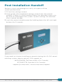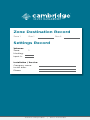
1
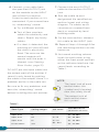
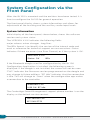
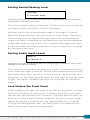
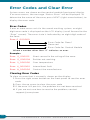
I N S TA L L AT I O N A N D
O P E R AT I O N S G U I D E
Qt 100
™
TM
www.csmqt.com
SOUND MASKING
|
|
800.219.8199
PAGING
|
MUSIC
Contents
Qt 100 Introduction3
Hardware Installation4
Installing the Control Module4
Wall Mount (back panel of the controller)
4
Connections to the Front Panel
5
Connect Paging or Music
5
Contact Closure5
Connecting Power6
Installing Qt Emitters7
Emitter Installation Order7
Custom Cabling Guidelines9
System Configuration via the Front Panel
10
System Information10
Setting Sound Masking Level11
Setting Audio Input Levels11
Lock/Unlock the Front Panel11
Error Codes12
Post Installation Handoff13
Settings Record13
Warranty14
2
CAMBRIDGE SOUND MANAGEMENT
Qt 100 INTRODUCTION
This manual covers system installation, masking level setting and
system maintenance. This introduction section discusses guidelines to
ensure effective sound masking coverage. The Qt 100 Configuration
App Manual, shipped with our Bluetooth dongle, describes how the
Qt 100 system can be configured using our companion iPad app.
The Qt 100 control module supports one zone of sound masking with
2 cable runs. Each run supports up to 60 emitters. The maximum
coverage area for the Qt 100 is 12,000 square feet (1,115 m2). The
module features one audio input for distribution of audio from
paging controllers or background music players.
It is important that the masking volume be set correctly to achieve
the full effectiveness of the Qt 100 system. If volume levels are set
too low, speech privacy will be reduced and workplace distractions
will become more apparent. If volume levels are set too high, the
masking sound could become a source of distraction. The higher the
setting that can be used comfortably, the better the acoustic privacy.
For a given open office design, including ceiling height, ceiling
material and workstation panel height, we can define the masking
volume required to achieve “normal acoustic privacy,” (i.e., normal
voices are unintelligible yet audible). In an open office environment,
the target background sound level is in the 45–48 dBA range, as
measured 3 feet (0.9 m) above floor level.
Similarly, for private offices, based on wall panel design and ceiling
construction, we can define masking volumes required to achieve
“confidential privacy,” (i.e., normal voices not audible). Most private
offices have a target background sound level in the 38–42 dBA range.
Setting the masking volumes can be approached in one of three
ways:
Best: The Qt 100 has a companion iPad app that takes acoustic
measurements and relays the results to the control module via
Bluetooth to set the appropriate masking sound level. See Qt 100
Configuration App Manual.
Good: If a sound level meter is available, it is recommended that the
control module’s masking volume be adjusted up or down to achieve
the following readings on the meter:
Sound Level Meter Readings Private Office Zones
38-42 dBA, averaged spatially within the office
Open Area Zones
45-48 dBA, measured 3 feet (0.9 m) above floor level
3
Q t 1 0 0 I N S TA L L AT I O N & O P E R AT I O N S G U I D E
OTHERWISE: If a sound level meter is not available, the
recommended levels are likely to be achieved in most environments
by setting the control module’s masking volumes as follows:
Control Module’s Masking Volume Settings
Private Office Zones
05-09, for all ceiling heights
Open Area Zones
13-16, for 08 ft. (2.4 m) ceilings
15-18, for 10 ft. (3 m) ceilings
17-20, for 12 ft. (3.7 m) ceilings
Masking volumes must be set sufficiently high to improve speech
privacy and reduce distraction but not so high that the masking
sound becomes obtrusive. Settings within the above ranges typically
accommodate both objectives. As a general rule, use the high end
of the range. Base final settings on site conditions and customer
preferences.
Hardware Installation
Installing the Control Module
NOTE: Always plug in/unplug power supply at wall outlet.
Wall Mount (attached to the back of the control module)
Remove the wall mount from the control module. Mount the wall
mount using the 4 screws and plastic anchors provided. Use a ¼
inch drill bit for the anchor hole. The included Plastic anchors are
#6 x 1" with #6 x 1 ¼" screws.
Use the bubble level on the wall mount to guide installation. Make
sure to completely tighten the screws to ensure proper mounting
of the front panel.
All connections are made to the control module and then the
module "snaps" into place on the wall mount.
4
CAMBRIDGE SOUND MANAGEMENT
Connections to the Front Panel
Connect Paging or Music
NOTE: The fixed terminal block can be removed for ease of connecting.
Balanced Audio Input: (Most often, but not always
characteristic of paging systems.) Connect signal
wires to + and - at the input. Connect the shield to
GND at the audio source.
Unbalanced Audio Input: (Typical of music systems.)
a. Mono Signals: Connect the mono signal wire
to both L and R (split the wire) on the block.
Connect the ground wire to GND.
b. Stereo Signals: Connect the respective signal
wires to L and R on the block. Connect the
ground wire to GND.
Contact Closure
The Qt 100 provides an instant shut-off capability for masking if
connected to a contact closure interface. The contact closure utilizes the
same connector as the audio input. To leverage this feature, connect a
two-conductor cable to the two connectors, labeled “contact”. The other
end of these conductors (treated as pairs/circuits) can be terminated on
closure mechanisms of choice.
1. To shut off masking, form a connection between the two conductors.
2. To resume masking, break the connection.
5
Q t 1 0 0 I N S TA L L AT I O N & O P E R AT I O N S G U I D E
Connecting Power
The controller comes standard with
a 24 V wall plug power supply. This
supply features a wall plug and a
fixed barrel connector.
Alternatively, power can be supplied
to the fixed block connector, which
allows for stripped and tinned
wires for added flexibility and
convenience.
The terminal block can be removed
for easy wiring. Simply connect the
positive and negative wires to the
terminal block and slide the terminal
block back onto the posts.
6
CAMBRIDGE SOUND MANAGEMENT
Installing Qt Emitters
Important Considerations:
• Each run has a maximum of 60 emitters!
• Each run supports a maximum cable length of 1000 ft.
• Each home run cable attached to the control module should be labeled by Zone # and Run #. Adding a logical name (e.g.
Marketing, Private Offices) is suggested. In addition, fill out "Zone Destination Record" at the end of this Guide.
• The module has two identical outputs, Run 1 and Run 2. All
emitters on Run 1 and Run 2 are controlled equally.
• Each job-made cable should be manufactured according to
ANSI/TIA/EIA Standard 568-B. See custom cabling guidelines
on page 9.
• Job-made cables should be tested with a LAN cable tester
before installation.
Emitter Installation Order
1. Set the masking output level
5. Push the emitter through the
to the maximum level of 30.
front of the hole in tile and
2. Refer to the emitter layout
and wiring diagram provided
by the dealer for cable run
connections.
3. Run home run cables from
control module to the location
of the first emitter for all runs.
4. Gather all ceiling tiles (per
layout drawing) that are to
secure it by pushing down
and twisting the locking ring
at the back of the emitter.
NOTE:
1. The “tombstone” hook on
the back of each emitter
is next to the INPUT jack.
This can help you find the
INPUT jack by touch.
receive emitters. Use the
supplied hole saw to cut holes
2. To adjust for unexpected
in designated tiles. Cut all
obstacles such as
tiles from the front. (Different
sprinkler heads, each
types of emitter housings are
emitter may be moved
available to attach in areas
up to two feet (one tile or
where there are no suspended
0.6 m) in any direction, if
ceiling tiles.)
necessary.
7
Q t 1 0 0 I N S TA L L AT I O N & O P E R AT I O N S G U I D E
6. Connect a run cable from
7. Connect the next OUTPUT
the specified OUTPUT jack
cable to the emitter OUTPUT
on the module to the INPUT
jack.
jack of the first emitter.
Listen to each emitter as it is
connected. If you cannot hear
its “whooshing” sound:
8. Run the cable to next
designated tile specified on
emitter layout and wiring
diagram. Tie cables up to
a. Try a different emitter.
structure or suspend from
b. Test all four previous
deck as required by local
cables for continuity and
shorts. Repair any faulty
cables.
building code.
9. On the next emitter, connect
this cable to the INPUT jack.
c. If a short is detected, the
10. Repeat Steps 4 through 9 for
masking will shut off until
the remaining emitters on the
the short is physically
home run.
fixed. The error on the
control module will
remain until the error is
cleared. (see Clearing
Error Codes, page 12)
DO NOT put the input cable into
11. Set sound masking volume
levels for each zone, using
either the front panel controls
or the software interface. Set
sound levels according to
Table 1.
the output port of the emitter. If
sound is only heard by putting
the cable in the output, there is a
problem earlier in the cable run.
NOTE:
The input jack of each
emitter bears this
symbol and is located
near the safety tie off
Be sure to fix any problems and
hear the “whooshing” sound
before installing the next emitter.
The output jack of
each emitter bears
this symbol
Table 1
Intended Result
Zone Type
Ceiling Height
Vol. Level
Open Area
8'
13 – 16
45 – 48 dBA
Open Area
10'
15 – 18
45 – 48 dBA
Open Area
12'
16 – 19
45 – 48 dBA
Private Office
ALL
05 – 09 +
38 – 42 dBA
(at listener ear level)
8
CAMBRIDGE SOUND MANAGEMENT
Custom Cabling Guidelines
For system compliance, follow these guidelines if custom cables are
required:
1. Use solid conductor 24 AWG CAT cable that meets local code
requirements.
2. If the system is installed in a return air plenum, the cable must be
plenum rated.
3. Shielding is not required. Unshielded twisted pair (UTP) cable is
acceptable.
4. Snagless boots are not required.
5. RJ-45 plugs must use the “bent 3-tine” RJ 45 plugs intended for
use with solid core CAT wire. Three tine plugs can be purchased
at a hardware store and from most CAT cable suppliers. DO NOT
USE the “aligned two-tine” type intended for stranded wire, as
they provide improper contact and may yield intermittent system
operation. The diagram below shows the cross section view of
both types.
6. Field test each cable after fabrication with the RJ-45 connectors
(before final installation), using a standard network LAN cable
tester, to check for continuity, shorts, and 1:1 (straight through)
connection.
CORRECT
RJ-45 connector
with bent type
INCORRECT
RJ-45 connector
with aligned type
9
Q t 1 0 0 I N S TA L L AT I O N & O P E R AT I O N S G U I D E
System Configuration via the
Front Panel
After the Qt 100 is mounted and the emitters have been tested, it is
time to configure the Qt 100 for general operation.
The front panel display shows system information and allows for
adjustment of the masking and the auxiliary audio input levels.
System Information
Initial display of the front panel, shown below, shows the software
version and system status.
The VERSION X.X.X indicates the following fields:
major release. minor changes . bug fixes
The BRx format is to identify the version of the internal code and
used as reference for technical support on rare occasions. Status
indicates if there are errors (see Error Format) or if the system is OK.
VERSION X.X.X
Status: OK
BRx
If the Bluetooth dongle used for configuration by the Qt 100
Configuration Application is installed, the following screen is
displayed. If the dongle is not installed, the screen will not be seen.
"FW1" indicates the firmware version programmed on the dongle and
may change in future editions. "BT Idle" indicates that the connection
is idle. This will change to “Conn” when the configuration app makes
a connection to the controller.
Bluetooth FW1
USB OK: BT Idle
The Cambridge Sound Management support phone number is on the
display as the default service contact.
For Service Call
617-349-3779
10
CAMBRIDGE SOUND MANAGEMENT
Setting Sound Masking Level
Masking
Z1 Volume: Mute
This figure shows that the format of the panel for configuring masking. Z1 stands for
zone 1 and it is currently set to mute.
The initial value of Mute is displayed. To adjust the level, use the up
and down arrows while this screen is displayed.
Settings within the recommended ranges (see page 3) should
optimize speech privacy without excessive distractions. Generally,
set masking volumes toward the high end of the recommended
range and adjust according to site conditions and user preferences.
If possible, measure the results with a sound level meter and check
for the achieved sound pressure level. Adjust as necessary or judge
by listening in the area.
Setting Audio Input Levels
Input A
Z1 Volume: 6
This figure shows the format of the panel for configuring the volume for input A. The
example shows Input A is level 6.
The system has one input for paging or music. If no paging and/or
music from the input is desired, set the audio volume level to mute.
The audio input levels are set in a similar way as the masking. Use
the arrows on the front panel to move left and right to find the input
A field. The input is enabled and level set using the up and down
arrows.
Lock/Unlock the Front Panel
If the configuration app was used to set the masking level, the app
could have locked the front panel. To unlock the front panel, hold
the left and right buttons for 5 seconds. The front panel display will
indicate that the panel has been unlocked. To lock the front panel,
repeat the process, hold the left and right buttons for 5 seconds.
If using the configuration app, the front panel will automatically
unlock when adjusting the masking level.
11
Q t 1 0 0 I N S TA L L AT I O N & O P E R AT I O N S G U I D E
Error Codes and Clear Error
System errors are shown on the control module front panel display.
If an error occurs, the message “Status: Error” will be displayed. To
determine the cause of the error, press NEXT (right arrow button), to
display the error code.
Error Codes
If one or more errors exist in the sound masking system, an eight
digit error code is displayed on the LCD display (scroll forward to the
“Error” screen). The error state is indicated by an eight digit code of
the form:
Error: 0_000000
Error Code for Zone 1
Reserved
Error Code for Control Module
Where a number other than “0” indicates an error.
Examples
Error: 0_000001
Short sensed in the wiring of the zone
Error: 0_000004
Emitter not working
Error: 2_000000
Over temperature
Error: 4_000000
Intermittent fault
Error: 8_000000
Contact the manufacturer
Clearing Error Codes
To clear an error that is currently shown on the display:
1. Press the right arrow button on the front panel to see the error
code
2. Press the up arrow to clear the error code
3. If the error still persists, the problem has not been resolved
4. If you are not sure how to resolve the problem, contact [email protected]
12
CAMBRIDGE SOUND MANAGEMENT
Post Installation Handoff
Perform a final walkthrough to satisfy all aspects of the
system performance:
1. Fill out the settings record.
2.Store guide with completed settings record near the control
module. If there is a hard module failure, the recorded values can
be used to reconfigure the system. System settings are retained
after a power outage.
3.Lock the control module panel by holding down the left and right
buttons for 5 seconds.
If you need assistance installing or commissioning this Qt 100 sound
masking system, please contact CSM support at:
1.800.219.8199 (Toll free within US & Canada)
617.349.3779 (Outside US & Canada)
[email protected] | www.csmqt.com/support
13
Q t 1 0 0 I N S TA L L AT I O N & O P E R AT I O N S G U I D E
Warranty:
Note: This equipment has been tested and found to comply with
the limits for a Class A digital device, pursuant to part 15 of the
FCC Rules. These limits are designed to provide reasonable
protection against harmful interference when the equipment
is operated in a commercial environment. This equipment
generates, uses, and can radiate radio frequency energy and, if
not installed and used in accordance with the instruction manual,
may cause harmful interference to radio communications.
Operation of this equipment in a residential area is likely to cause
harmful interference in which case the user will be required to
correct the interference at his own expense.
Modifications not expressly approved by the manufacturer could
void the user’s authority to operated the equipment under FCC
rules.
Warranty Coverage — Qt Emitters™
Cambridge Sound Management, LLC (the “warrantor”) will, for
a period of five (5) years, starting with the date of purchase,
warrant that the Qt Emitters™ (the “speakers”) will be free of
defects in materials and workmanship that interfere with proper
operation as a sound masking, paging and music speaker system.
During that period, the warrantor will, at its option, either (a)
repair the speaker, or (b) replace the speaker. The decision to
repair or replace will be made by the warrantor.
Warranty Coverage — Qt control unit
The warrantor will, for a period of one (1) year, starting with the
date of purchase, warrant that the Qt control unit (the “system”)
will be free of defects in materials and workmanship that
interfere with its proper operation as a sound masking, paging
and music distribution control system. During that period, the
warrantor will, at its option, either (a) repair the system, with
new or refurbished parts, or (b) replace the system with a new
or refurbished system of equal functionality at no charge. The
decision to repair or replace will be made by the warrantor.
All software installed in the Qt system is warranted to
substantially conform to its published specifications. In no event
does the warrantor warrant that the software is error free or
that the customer will be able to operate the software without
problems or interruptions. The warrantor will, from time to time,
make available software bug fixes. It is the responsibility of the
purchaser to download and install these software modifications.
Except for the forgoing, all software and software upgrades are
provided AS IS.
The following terms apply to all
These warranty terms are extended only to the original purchaser of a
new product. A purchase order or other proof of the original purchase
date and purchaser is required for warranty service.
14
CAMBRIDGE SOUND MANAGEMENT
Obtaining warranty repairs: Please access and review online help
resources for the product before requesting warranty service. If
the product is still not functioning properly after making use of
these resources, please contact Cambridge Sound Management
for a return authorization number. All returns are to be prepaid.
The warrantor will pay return surface freight within the
continental United States on warranty repairs. All customs and
freight charges in excess of surface freight within the United
States will be born by the purchaser.
Warranty Limits and Exclusions
This warranty ONLY COVERS failures due to defects in materials
or workmanship, and DOES NOT COVER normal wear and tear
or cosmetic damage. THIS WARRANTY DOES NOT COVER USE
OF THE SYSTEM WITH ANY OTHER SPEAKER OR EMITTER
MANUFACTURED BY ANY ENTITY, ORGANIZATION OR
COMPANY OTHER THAN CAMBRIDGE SOUND MANAGEMENT,
LLC OR USE OF THE SYSTEM FOR ANY PURPOSE OTHER
THAN SOUND MASKING AND/OR PAGING AND/OR MUSIC
DISTRIBUTION. THIS WARRANTY DOES NOT COVER THE USE
OF ANYTHING OTHER THAN CAT-3 OR EQUIVALENT, 24 GAGE
CABLING. The warranty ALSO DOES NOT COVER damages
that occurred in shipment, failures that are caused by products
not supplied by the warrantor (e.g., replacement power
supplies) or failures that result from accidents, misuse, abuse,
neglect, mishandling, misapplication, alteration of any sort,
installation, use as a system driver during speaker installation,
set-up adjustments, misadjustment of controls, improper
maintenance, power line surge, lightning damage, power surges,
modification, rental use, service by anyone other than the
warrantor or damage that is attributable to acts of God.
THERE ARE NO EXPRESS OR IMPLIED WARRANTIES
EXCEPT AS LISTED UNDER “WARRANTY COVERAGE.” THE
WARRANTOR IS NOT LIABLE FOR ANY INCIDENTAL OR
CONSEQUENTIAL DAMAGES RESULTING FROM THE USE OF
THE PRODUCT OR ARISING OUT OF ANY BREACH OF THIS
WARRANTY. As an example, this specifically excludes damages
for lost time, lost use of the system, cost of removal or reinstallation of the system or travel to and from the purchaser’s
location. ALL EXPRESS AND IMPLIED WARRANTIES ARE
LIMITED TO THE PERIOD OF THE WARRANTY.
This warranty provides specific legal rights, and there may
be others that vary from state to state or in the country of
compliant use. Therefore, certain additional exclusions may
apply.
15
Q t 1 0 0 I N S TA L L AT I O N & O P E R AT I O N S G U I D E
TM
Zone Destination Record
Zone 1Run 1
Run 2
Settings Record
Volumes:
Zone:
1
Masking:
Input A:
Installation / Service:
Company name:
Install date:
Phone:
www.csmqt.com
|
800.219.8199