1
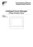
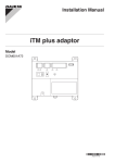
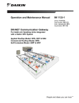
Commissioning Manual
Supplementary Volume
intelligent Touch Manager
Layout Screen Creation Tool
Model
DCM601A51
MONITOR
LAN SW
FRONT BACK
SERVICE LAN
ON
SLAVE
OFF
MASTER
CPU ALIVE LAN LINK D
D
BACKUP
MASTER
RESET
MONITOR
Contents
Layout Screen Creation Tool...................................................................................2
•• Launching the Layout Screen Creation Tool................................................................................ 3
•• Setting Up the Screen................................................................................................................. 6
•• Adding and Editing Areas or Management Points..................................................................... 10
•• Exporting the Screen Data Output............................................................................................ 14
•• Importing the Layout Screen Data............................................................................................. 17
1
Commissioning Manual (Layout Screen Creation Tool) EM11A024
DCM601A51 intelligent Touch Manager
Layout Screen Creation Tool
The Layout Screen Creation Tool, which is provided as part of the Preconfiguration Tool Set and
available with the Layout Screen Functionality dealer option, allows you to create layout screens in
advance. For information on how to log into the Preconfiguration Tool Set as well as the detailed
description of the tool set, see the appropriate pages of the Commissioning Manual.
You need a separate PC to run the Layout Screen Creation Tool.
See the following table for the hardware and software requirements to run the Layout Screen
Creation Tool:
Function
Requirement
PC to run the pre-engineering tool
OS:Windows XP Professional SP3 (32 bit)
Windows VISTA Business SP2 (32 bit)
Windows 7 Professional SP1 (32 bit, 64 bit)
CPU: Intel Core 2 Duo 1.2 GHz or equivalent
RAM: Minimum 2 GB or higher
Free HDD Space: 10 GB or larger
Network: 100BASE-TX or higher network connection
Display Resolution: 1024 × 768 or higher *
Network
100Base-TX
Real transfer rate: 115 kbps or higher
Supported security software
McAfee 2011
Norton 2011
Virus Buster 2011
Flash Player
Version 11.1
Web browser
Internet Explorer 8, 9
Firefox 10.0
* When the height of the display resolution is 768 pixels, you should enable the “Auto-Hide the Task Bar”
setting.
Commissioning Manual (Layout Screen Creation Tool) EM11A024
DCM601A51 intelligent Touch Manager
2
Use the following procedures to work with the Layout Screen Creation Tool:
Launching the Layout Screen Creation Tool
1. Log into the Preconfiguration Tool Set and go to the Main Window.
Main screen
(1)
(3)
(2)
(5)
(4)
2. Click the four corners of the window in the ascending order of the numbers indicated on the
figure above and finally click the Exit button to access the password prompt dialog box.
3. Enter “daikin” as the password and then click the OK button to bring up the following dialog box,
which contains the Edit Layout Screen button.
3
Commissioning Manual (Layout Screen Creation Tool) EM11A024
DCM601A51 intelligent Touch Manager
(1)
(2)
4. Under the section numbered (1) in the figure above, create a folder for a new property or select
the folder for an existing property. (For more information, see “4-7. Pre-engineering” in the
Commissioning Manual (EM11A021 / EM11A022).
Click the Edit Layout Screen button (2) to bring up the Edit Screen window.
Commissioning Manual (Layout Screen Creation Tool) EM11A024
DCM601A51 intelligent Touch Manager
4
(3)
(4)
(5)
(6)
(7)
The Edit Screen window is divided into the operation pane (3) and the display pane (4). While you
are editing the screen in the operation pane (3), the display pane (4) provides a preview of how the
screen will be displayed on iTM. You can interact with the display pane (4) in the same way as when
you are working within iTM; for more information, see the User’s Manual (EM11A015 / EM11A017).
To edit the layout screen, you can perform actions such as adding, deleting, or moving areas or
management points by left clicking the appropriate buttons in the operation pane (3).
Alternatively, you can point to a certain part on the display pane (4) and then click the right mouse
button or press the appropriate key to perform your desired action.
The following table provides a list of available mouse and keyboard actions:
Target
Action
Background image
Left click
−
Select
Left click & drag
Rubber band select
Move
Right click
[Bring up a popup menu]
Add an area or
management point
Set up the screen
Set up the list
[Bring up a popup menu]
Delete
Set up the coordinates
Delete key
−
Delete the selected
displayed information
Cursor keys
−
Move the selected
displayed information
Ctrl key
+ left click
−
Select multiple items
Mouse action
Keyboard action
Keyboard action
+ mouse action
Icon / auxiliary
information
Mouse and Keyboard Actions
5
Commissioning Manual (Layout Screen Creation Tool) EM11A024
DCM601A51 intelligent Touch Manager
During an edit session, you can undo the previous action by clicking the Undo button (5). You
can undo up to 10 most recent actions since the last save, screen change, or delete operation.
NOTE
Certain actions cannot be undone.
Setting Up the Screen
The screen list (6) in the operation pane (3) provides a list of registered screens. As you select a
screen from this list, a preview of the selected screen appears in the display pane (4). You can
assign up to 60 screens to a single property.
1. Click the Add button (7) to bring up the Screen Settings dialog box.
(8)
(9)
The text box (8) allows you to enter the screen name by accepting up to 20 characters.
The text box (9) allows you to specify the background image. To change the image to use as the
background, click the Modify button. As the background image, you can use any JPEG image
file up to 500 KB in size and containing a 600 pixel × 500 pixel to 1500 pixel × 1000 pixel image.
Click the OK button to save the changes and return to the Edit Screen window.
The background image you have just added appears at the bottom of the list.
You can reorder the screen list using the
and
buttons.
NOTE
The file name of the imported background image may be different from the original name
because it is automatically converted for management in the tool when the layout data is saved.
Commissioning Manual (Layout Screen Creation Tool) EM11A024
DCM601A51 intelligent Touch Manager
6
(11)
(10)
(13)
(12)
2. You can select a screen from the screen list and click the Screen Settings button (10) to bring
up the Screen Settings dialog box, where you can change the name and background image of
the screen (to do so, follow the instructions given in step 1).
If you want to delete a screen, select it from the screen list and click the Delete button (11). You
can then delete the screen by clicking the OK button on the confirmation dialog box that
appears. Click the Back button (12) to go back to the previous screen. You can go back up to 10
screens.
NOTE
Once you have deleted a screen, you cannot recover the deleted screen since the Undo button
cannot be used to undo the deletion. Take extreme care.
3. Click the List Settings button (13) to bring up the Screen Change List Settings dialog box.
7
Commissioning Manual (Layout Screen Creation Tool) EM11A024
DCM601A51 intelligent Touch Manager
(14)
(15)
(16)
(17)
The name of the currently selected screen is displayed in the filed numbered (14) in the figure above.
This window allows you to set up the contents of the Screen Change List associated with the
currently selected screen.
The list (15) displays the screens currently included in the Change List.
The list (16) shows screens available for inclusion in the Change List.
To include an available screen in the Change List, select the screen from the list (16) and then
click the < button to move it to the list (15).
To exclude a screen from the Change List, select the screen from the list (15) and then click the
> button to move it to the list (16).
To reorder the contents of the list (15), use the
or
button (17).
Click the OK button to save the changes and return to the Edit Screen window.
Commissioning Manual (Layout Screen Creation Tool) EM11A024
DCM601A51 intelligent Touch Manager
8
NOTE
You need to make the screen change list setting for each screen.
During operation by iTM, the list specified for each screen is displayed and you can switch to
only the screens shown in the list.
Example)
Screen A
Screen B
Screen change list setting
Screen change list setting
Screen B
Screen A
Screen C
Screen C
Screen D
Screen C
Screen D
Screen change list setting
Screen change list setting
Screen A
Screen A
Screen B
Changable screens
A
B
C
D
A
B
×
C
×
D
×
×
By using the screen change list setting, you can limit the screen change; for example changing
to a specific screen can be limited to only from specified screens.
In the example above, changing to the screen D is possible only from the screen A.
Make the setting of changable screens according to the customer demand.
9
Commissioning Manual (Layout Screen Creation Tool) EM11A024
DCM601A51 intelligent Touch Manager
Adding and Editing Areas or Management Points
(18)
1. Click the Add button (18) to bring up the Add Area / Mng Point dialog box.
(19)
(20)
(21)
(22)
The name of the screen to add areas or management points is displayed in (19).
This dialog box does not display any of the automatically generated default areas.
From the Type combo box (20), choose one of the following types: All, Indoor, Ventilator, Analog,
Pulse, Outdoor, Area. Select areas and/or management points you want to add from the list (21),
which is now populated with a list of areas and management points available with your selected
type. You can add up to 20 items at the same time.
2. Click the Display Information button (22) to bring up the Displayed Information Settings dialog
box, where you can set up the displayed information for your selected areas or management points.
The Displayed Information Setup dialog box has 8 tabs that correspond to the types of your
selected areas or management points.
Each tab provides a number of check boxes that control the display of various items. All of the
items checked on the tabs will be displayed on the layout screen.
By factory default, all the items are checked. So be sure to uncheck any items that you do not
want to have displayed.
Commissioning Manual (Layout Screen Creation Tool) EM11A024
DCM601A51 intelligent Touch Manager
10
Displayed Information Settings dialog box (Indoor tab)
Displayed Information Settings dialog box (Ventilator tab)
Displayed Information Settings dialog box (Dio tab)
Displayed Information Settings dialog box (Analog tab)
Displayed Information Settings dialog box (Pulse tab)
Displayed Information Settings dialog box (Outdoor tab)
Displayed Information Settings dialog box (Chiller tab)
Displayed Information Settings dialog box (Area tab)
When you are done, click the OK button to save changes and return to the Add Area / Mng Point
dialog box.
3. When you finish selecting the areas and management points, click the OK button to close the
Add Area / Mng Point dialog box and return to the Edit Screen window.
11
Commissioning Manual (Layout Screen Creation Tool) EM11A024
DCM601A51 intelligent Touch Manager
(27)
(28)
(24)
(23)
(25)
(26)
4. The areas and management points you have just added are displayed on the screen.
To delete an area or management point, select the area or management point and then click the
Delete button (23).
To move an area or management point, select the area or management point using the mouse
and drag it to a new location. Alternatively, click the Coordinate Settings button (24) and then
enter the desired coordinates (in pixels) to move the area or management point to your specified
location. The origin of coordinates is located at the upper left corner of the background image
with the X axis extending positively from left to right and with the Y axis extending positively from
up to down.
You can use the Layout buttons (25) to align vertically or horizontally multiple areas or
management points.
← button:Aligns the left edges of the selected areas or management points to the left edge of
the leftmost of them.
→ button:Aligns the right edges of the selected areas or management points to the right edge
of the rightmost of them.
↑ button:Aligns the upper edges of the selected areas or management points to the upper
edge of the uppermost of them.
↓ button:Aligns the lower edges of the selected areas or management points to the lower edge
of the lowermost of them.
You can use the Alignment buttons (26) to evenly arrange (justify) vertically or horizontally
multiple areas or management points.
Commissioning Manual (Layout Screen Creation Tool) EM11A024
DCM601A51 intelligent Touch Manager
12
←→ button:Anchors in place the selected areas or management points with the leftmost left
edge and with the rightmost right edge and justifies horizontally all the other in
between.
↑↓ button:Anchors in place the selected areas or management points with the uppermost
upper edge and with the lowermost lower edge and justifies vertically all the other
in between.
NOTE
•• The Alignment buttons are for aligning “display areas”. The areas may not be evenly
displayed on iTM depending on the number of displayed characters.
•• The icon size is fixed to 76 px (W) x 38 px (H) and cannot be changed.
•• Up to 100 icons can be displayed on a screen.
5. When you are done configuring all necessary settings, click the Save button (27) to save the
changes to the layout screen data, and then click the Exit button (28) to return to the
Preconfiguration Tool Set.
NOTE
Once you have saved a screen using the Save button, you cannot revert the screen to the
previous state since the Undo button cannot be used to undo the save. Take extreme care.
13
Commissioning Manual (Layout Screen Creation Tool) EM11A024
DCM601A51 intelligent Touch Manager
Exporting the Screen Data Output
When you want to use the Layout Screen Creation Tool to work on the data of an existing property
created in the iTM unit, you can export the data from iTM to a USB memory storage device. To do
so, use the following procedures:
1. On iTM Standard View window, touch the Menu List button to bring up the Menu List window.
(3)
(1)
(2)
(4)
2. Touch the four corners of the screen in the indicated order. The Password Input dialog appears.
3. Enter the service password “daikin” and touch the OK button to log into the SE Mode.
Commissioning Manual (Layout Screen Creation Tool) EM11A024
DCM601A51 intelligent Touch Manager
14
(29)
Furthermore, if the screen is locked, entering the service password instead of the administrator
password after carrying out the special operation indicated below, allows you to unlock the
screen and log into the SE Mode.
(3)
(1)
(2)
(4)
4. Touch the Layout Setup button (29) to bring up the Layout Setup window.
NOTE
The Layout Setup button is not displayed when the iTM unit does not contain any layout screen
data.
15
Commissioning Manual (Layout Screen Creation Tool) EM11A024
DCM601A51 intelligent Touch Manager
(30)
5. Insert the USB memory storage device into iTM unit and then touch the Layout Screen Data
Output button (30). Export the data by touching the Yes button on the confirmation dialog box
that appears.
When the data has been exported, the folder where the data is stored is displayed on the dialog
box. Take note of the folder and then touch the Close button to exit.
Commissioning Manual (Layout Screen Creation Tool) EM11A024
DCM601A51 intelligent Touch Manager
16
Importing the Layout Screen Data
After you have edited layout screen data in the Preconfiguration Tool Set, you can save the data on
a USB memory storage device and import it into iTM unit. To do so, use the following procedures:
For more information on how to save data on a USB memory storage device, see “4-7. Preengineering” in the Commissioning Manual (EM11A021 / EM11A022).
1. Open the Service Settings tab and touch the Layout Setup button to bring up the Layout Setup
window.
(31)
2. Insert the USB memory storage device into the iTM unit and then touch the Layout Screen
Data Input button (31). Import the data by touching the Yes button on the confirmation dialog
box that appears. When the data has been imported, iTM restarts automatically.
17
Commissioning Manual (Layout Screen Creation Tool) EM11A024
DCM601A51 intelligent Touch Manager
EM11A024 (1208) HT