1
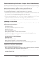
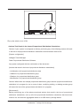
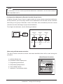
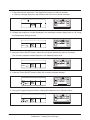
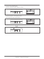
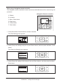
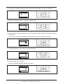
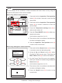
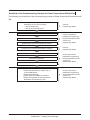
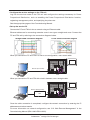
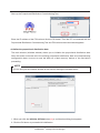
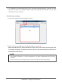
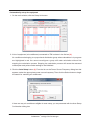
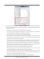
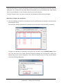
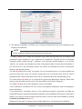
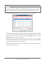
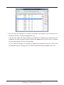
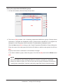
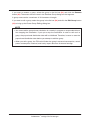
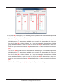
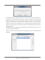
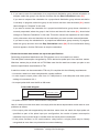
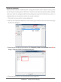
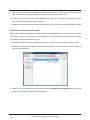
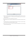
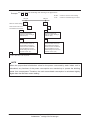
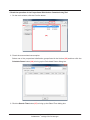
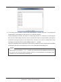
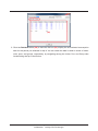
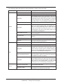
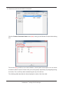
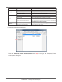
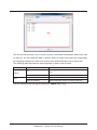
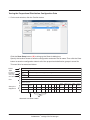
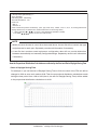
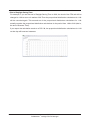
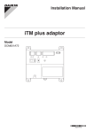
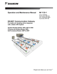
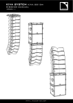
Commissioning Manual
Supplementary Volume
intelligent Touch Manager
Commissioning for Power Proportional Distribution
Model
DCM601A51
MONITOR
LAN SW
FRONT BACK
SERVICE LAN
ON
SLAVE
OFF
MASTER
CPU ALIVE LAN LINK D
D
BACKUP
MASTER
RESET
MONITOR
Contents
Commissioning for Power Proportional Distribution............................................2
•• Preparation for Commissioning................................................................................................... 2
•• Precautions to Take Before Commissioning................................................................................ 2
•• Workflow of the Commissioning Process for Power Proportional Distribution........................... 11
•• Saving the Proportional Distribution Configuration Data........................................................... 37
•• How the Proportional Distribution Calculations are affected by the
Start and End of Daylight Saving Time...................................................................................... 38
1
Commissioning Manual (PPD) EM11A027
DCM601A51 intelligent Touch Manager
Commissioning for Power Proportional Distribution
Power Proportional Distribution is a function that proportionally distributes the total power used by
the air conditioners in a rental building and the like, measured using an electricity meter among the
tenants. Proportional distribution calculation can also be exported to a CSV file.
Commissioning is required before Power Proportional Distribution can be used.
The commissioning process can be divided into the following three major steps:
1. Activate the Power Proportional Distribution function on the iTM unit. For more information, see
“5-1. Activation” in the Commissioning Manual (EM11A021/EM11A022).
2. Perform commissioning tasks from the iTM unit. For more information, see “10-1. Power
Proportional Distribution Function” in the User’s Manual (EM11A015/EM11A017).
3. Perform the commissioning tasks from the service PC using the procedures described herein.
Preparation for Commissioning
Prepare a PC for use in the commissioning for Power Proportional Distribution. The service PC
must meet the following requirements:
OS: Windows XP SP3
CPU: Pentium III 800MHz or equivalent at a minimum
RAM: 256 MB or higher
HDD: 2 MB or larger free space
Network: Ethernet 10BASE-T or higher network connection
Other: 800 × 600 or higher resolution and a video card capable of displaying 256 colours
OS: Windows Vista SP2/Windows7 SP1
CPU: Intel Core2 CPU 1.86GHz or equivalent
RAM: 1GB or higher
HDD: 2 MB or larger free space
Network: Ethernet 100BASE-T or higher network connection
Other: 800 × 600 or higher resolution and a video card capable of displaying 256 colours
Precautions to Take Before Commissioning
•• Check the Backup Battery Enable Switch
Before commencing the commissioning process for Power Proportional Distribution, make sure
that the backup battery enable switch of the iTM unit is turned on.
If the backup battery enable switch is not turned on, proportional distribution calculations will be
lost when the power is lost.
Commissioning Manual (PPD) EM11A027
DCM601A51 intelligent Touch Manager
2
Enlarged view
ON
OFF
MONITOR
LAN SW
FRONT BACK
ON
SLAVE
OFF
MASTER
D
BACKUP
SERVICE LAN
CPU ALIVE LAN LINK D
MONITOR
MASTER
RESET
Flip up the switch to turn it ON.
•• Actions That Result in the Loss of Proportional Distribution Calculations
Caution: If your system is configured as follows, performing any of the following actions will result
in the loss of all proportional distribution calculations that have been made so far:
[System configuration]
intelligent Touch Manager
Power Proportional Distribution Software
Any system configured with the combination of the above two.
[Actions that result in the loss of proportional distribution calculations]
•• Initialization of all proportional distribution data
•• Addition of a proportional distribution group
•• Deletion of a proportional distribution group
•• Modification of a proportional distribution group
Caution: When there are multiple proportional distribution groups and the proportional distribution
calculation is in progress for one or more of them, modifying, adding, or deleting another group
will cause the loss of the groups whose calculation is in progress.
[Workaround]
Before performing any of the above mentioned actions that result in the loss of proportional
distribution calculations, sum up all of the proportional distribution calculations that have been
made so far, and save the aggregated results on a USB memory storage device.
3
Commissioning Manual (PPD) EM11A027
DCM601A51 intelligent Touch Manager
NOTE
For information on how to save proportional distribution calculations, see the User’s Manual
(EM11A015/EM11A017).
•• Configure the Addresses for Remote Controller Group Control
If Remote Controller Group Control is applied within the system where proportional distribution
will be performed, you must assign central control addresses to all the slave remote controllers
that belong to the groups. Otherwise, none of the indoor units controlled by the slave remote
controllers can take advantage of proportional distribution.
To configure the addresses, use the following procedures:
Groups
outdoor
unit
iTM
Address
1-00
Address
1-01
Address
1-02
indoor
unit
indoor
unit
indoor
unit
MONITOR
Unit
No.0
Unit
No.1
Unit
No.2
When using a Wired remote controller:
The Wired remote controller's buttons and areas identified below will be used during this
procedure:
<Wired Remote Controller>
A Address display area
B Parameter number display area
C Programming time buttons
A
D Temperature setting buttons
B
C
D
E Timer ON/OFF button
F Inspection / Test operation button
E
F
Commissioning Manual (PPD) EM11A027
DCM601A51 intelligent Touch Manager
4
1. Press and hold the Inspection / Test Operation button for at least 4 seconds.
A “Setting” message appears in the middle of the LCD of the remote controller.
HH
2. Change the parameter number displayed in the parameter number display area to “30” using
the Temperature Setting buttons.
UNIT NO.
GROUP
SETTING
3. Using the Timer ON/OFF button, select the unit whose address you want to configure.
The currently assigned address appears in the address display area.
UNIT NO.
GROUP
SETTING
4. Press the Timer ON/OFF button to blink the currently assigned address.
UNIT NO.
GROUP
SETTING
5. Using the Programming time buttons, change the address to your desired number.
UNIT NO.
GROUP
5
SETTING
Commissioning Manual (PPD) EM11A027
DCM601A51 intelligent Touch Manager
6. Press the Timer ON/OFF button.
Now your specified DIII-NET address is in effect.
UNIT NO.
GROUP
SETTING
7. Press the Inspection / Test Operation button.
You are returned to the normal screen.
UNIT NO.
GROUP
SETTING
HH
Commissioning Manual (PPD) EM11A027
DCM601A51 intelligent Touch Manager
6
When using a Navigation remote controller:
The Navigation remote controller’s buttons and areas identified below will be used during this
procedure:
<Navigation Remote controller>
A Display
B Up button
C Menu / Enter button
A
B
D Right button
E Cancel button
C
F Down button
D
E
F
1. Press and hold the Cancel button for at least 4 seconds.
The [Field Setting] menu appears.
Cool
00 00
Set temp Room
30 C
30 C
2. Select [Group No. Setting] using the Up and Down buttons, and then press the Menu / Enter
button.
The [Group No. Setting] menu appears.
Field setting
1/2
Test operation ON/OFF
Register Service Contract
Field setting list
Group No. s e t t i n g
Indoor unit Airnet No. set
Error record
Return
Setting
3. Select [Group No. setting (Unit)] using the Up and Down buttons, and then press the Menu /
Enter button.
Group No. s e t t i n g
Group No. s e t t i n g (Group)
Group No. s e t t i n g ( U n i t )
Return
7
Setting
Commissioning Manual (PPD) EM11A027
DCM601A51 intelligent Touch Manager
4. Using the Up and Down buttons, select the unit whose address you want to configure.
Group No. s e t t i n g (Unit)
Unit No
1
Group No
Set
1-02
Return
5. Select the Group number by pressing the Right button.
Group No. s e t t i n g (Unit)
Unit No
1
Return
Group No
Set
1-02
Release
6. Put the currently assigned address into the released (unassigned) state by pressing the Menu /
Enter button.
The “Set” text changes to “Release”. This means that you can change the address.
Group No. s e t t i n g (Unit)
Unit No
1
Return
Group No
Release
1-02
Change
7. Change the address using the Up and Down buttons.
Group No. s e t t i n g (Unit)
Unit No
1
Return
Group No
Release
1-01
Change
8. Press the Menu / Enter button.
Now your specified DIII-NET address is in effect.
Group No. s e t t i n g (Unit)
Unit No
1
Return
Group No
Set
1-01
Release
Commissioning Manual (PPD) EM11A027
DCM601A51 intelligent Touch Manager
8
9. Press the Cancel button three times to return to the normal screen.
Group No. s e t t i n g (Unit)
Unit No
1
Return
Cool
Group No
Set
1-01
Release
00 00
Set temp Room
30 C
9
30 C
Commissioning Manual (PPD) EM11A027
DCM601A51 intelligent Touch Manager
NOTE
You can identify the air conditioner number associated with each indoor unit by using the
Forced Fan ON function of the remote controller.
When using a Wired remote controller:
Mode number
1. Press and hold the Inspection / Test operation
button (1) for at least 4 seconds to enter the field
Unit number
setup mode.
2. Press and hold the Inspection / Test operation
UNIT NO.
GROUP
Group number
SETTING
button (1) for at least 4 seconds to enter the
service mode.
(3)
3. Press the Temperature setting button (2) to
(2)
select mode number “43”.
(1)
4. Press the Timer ON/OFF button (3) to select your
desired unit number.
(Unit numbers range from 0 to 15.)
5. Then the fan of the air conditioner associated with
the indoor unit begins rotating.
6. Press the Inspection / Test operation button (1)
to return to the normal mode.
When using a Navigation remote controller:
1. Press and hold the Cancel button (1) for at least
Field setting
4 seconds to enter the field setting mode.
1/3
Indoor unit. AirNet Address
Error History
Indoor Unit Status
Outdoor Unit Status
Forced Fan ON
Switch Main Sub Controller
Setting
2. Using the Up and Down buttons (2), select
[Forced Fan ON] from the menu. Then press the
Menu / Enter button (3) to confirm the selection.
3. On the Forced Fan ON screen that appears,
(2)
select your desired unit number using the Up and
(3)
(2)
Down buttons (2).
(1)
(Unit numbers range from 0 to 15.)
4. Then the fan of the air conditioner associated with
Forced Fan On
Unit No.
the indoor unit begins rotating.
5. Press the Cancel button (1) to return to the
0
normal mode.
Commissioning Manual (PPD) EM11A027
DCM601A51 intelligent Touch Manager
10
Workflow of the Commissioning Process for Power Proportional Distribution
The following is the workflow of the commissioning process for Power Proportional Distribution with
iTM:
Configure the settings for proportional
distribution ( in the service mode)
•• Set up the DIII port
•• Set up the pulse input port
Set up the service PC
Connect the service PC and the iTM unit
Initialize the proportional distribution method
Configure the proportional distribution settings
Set up the ports
Set up the equipment
Set up the proportional distribution groups
Operation checks
•• Check that the watt-hour meters are up
to the specifications
•• Check the pulse input
•• Check the accumulated consumption
•• Check the operation of the Proportional
Distribution Commissioning Tool
11
Commissioning Manual (PPD) EM11A027
DCM601A51 intelligent Touch Manager
iTM unit
Engineering details
Power Proportional
Distribution engineering
tasks performed from the
service PC
Engineering details
iTM unit
Engineering details
Power Proportional
Distribution engineering
tasks performed from the
service PC
Engineering details
Power Proportional
Distribution engineering
tasks performed from the
service PC
Engineering details
•• Configure the service settings on the iTM unit
Log into the service mode of the iTM unit and configure the settings necessary for Power
Proportional Distribution, such as enabling the Power Proportional Distribution function,
registering management points, and specifying the pulse rate.
See the appropriate pages of the Commissioning Manual.
•• Set up the service PC
Connect the PC and iTM unit into a network using an Ethernet cable.
Ethernet cables use for connecting networks come in two types: straight and cross. Connect the
PC and iTM unit by referring to the connection diagrams below.
Straight cable connection diagram
Cross cable connection diagram
When you connect the PC and iTM in a one-to-one configuration, use a cross cable.
Ethernet (Cross cable)
iTM
PC
When you connect the PC and iTM with a hub in between, use a straight cable.
Ethernet (Straight cable)
Hub
iTM
PC
Once the cable connection is completed, configure the network connection by entering the IP
addresses and subnet masks.
For more information on network configuration, see “6-2. Web Remote Management” in the
Commissioning Manual (EM11A021/EM11A022).
Commissioning Manual (PPD) EM11A027
DCM601A51 intelligent Touch Manager
12
Start up the Proportional Distribution Commissioning Tool.
Enter the IP address of the iTM unit and click the OK button. Then the PC is connected with the
Proportional Distribution Commissioning Tool and iTM unit and the main window appears.
•• Initialize the proportional distribution data
The main window (Initialize window) allows you to initialize the proportional distribution data.
Since this action will erase all of the existing proportional distribution data and commissioning
configuration data, be sure to save the data on a flash memory device or the like before
proceeding.
NOTE
You can bring up the Initialize window at any time by clicking the Initialize button.
(1)
1. When you click the Initialize All Data button (1), a confirmation dialog box appears.
2. Click the OK button to proceed with initialization.
13
Commissioning Manual (PPD) EM11A027
DCM601A51 intelligent Touch Manager
3. The initialization process begins. Wait until a completion message appears, and then click the
OK button to return to the Initialize window. Check if all data has been deleted. If so, the data
initialization step is complete.
•• Check the port settings
1. On the main window, click the Setup Port button.
(2)
2. All of the Pi ports configured on the iTM unit appear in the list (2).
Make sure that each port, which is listed with its port name, group name, type, and pulse rate,
is correctly configured. If anything is incorrect, exit from the commissioning tool and then fix
the problem on the iTM unit.
NOTE
•• Port names “Extension 1 to 28” correspond to the port configuration with iTM Plus
Adaptor.
•• For the Internal Pi, consumption power cannot be used for PPD charge billing.
Commissioning Manual (PPD) EM11A027
DCM601A51 intelligent Touch Manager
14
•• Automatically set up the equipment
1. On the main window, click the Setup Unit button.
(3)
(4)
2. A list of equipment (air conditioners) connected to iTM is shown in the list box (3).
Air conditioners belonging to a proportional distribution group whose calculation is in progress
are highlighted in red. You cannot reconfigure a group still under calculation without first
stopping the calculation process. Stopping the calculation process will cause the assumed
consumption and pulse number settings to be initialized.
3. Click the Auto Setup button (4). From the list on the Power Source Frequency dialog box that
appears, select the appropriate power source frequency. Then click the Select button to begin
the search for matching air conditioners.
If there are any air conditioners eligible for auto setup, you are presented with the Auto Setup
Confirmation dialog box.
15
Commissioning Manual (PPD) EM11A027
DCM601A51 intelligent Touch Manager
4. The dialog box provides a list of air conditioner numbers and model names. Configure the
proportional distribution settings conditions by selecting the appropriate radio buttons under
“Calculating Condition”.
The following is the description of the radio buttons on this dialog box.
•• The Power Proportional Distribution radio buttons: Specify whether or not to perform
proportional distribution calculation on the listed air conditioners.
If you choose “No”, they are excluded from proportional distribution.
•• The include power during STOP radio buttons: Specify whether or not to add the power
consumed when the air conditioner is stopped (i.e., the power consumption by the crank
case heater) to the actual power consumption.
If you choose “Yes”, the system will apply proportional distribution to the power consumption
by the crank case heater and add the resulting amount to the actual power consumption.
If you choose “No”, the system will separately display the power consumption in the stopped state.
•• The include power of Heater radio buttons: Specify whether or not to add the power
consumption by the indoor unit heater to the assumed power consumption.
Choose “Yes” when the indoor unit is equipped with an optional heater.
•• The include power of Fan radio buttons: Specify whether or not to add the power
consumption by the indoor unit fan to the assumed power consumption.
When the electrical system of the indoor unit is connected to the watt-hour meter and the
pulse input is enabled, you can choose “Yes” to include the power consumption by the
indoor unit in the proportional distribution calculation.
Choose “No” if there is no pulse input from the indoor unit electrical system.
Commissioning Manual (PPD) EM11A027
DCM601A51 intelligent Touch Manager
16
Click the OK button to apply the settings to all of the listed air conditioners and exit from the
dialog box. Air conditioners that have been automatically set up are identified by “Auto Setup
Done” text that appears in the Comment column on the main window.
Click the Cancel button if you want to exit from the dialog box without saving changes.
•• Manually configure the equipment
5. Use the following procedure to manually set up air conditioners and ventilators that cannot be
automatically set up.
(You can also edit the information for already set up equipment using the same procedure.)
(6)
(5)
Choose your desired air conditioner from the list (5) and then click the Modify Setup button
(6). From the list on the Power Source Frequency dialog box that appears, select the
appropriate power source frequency. Then click the Select button to bring up the Model
Information Editing dialog box.
17
Commissioning Manual (PPD) EM11A027
DCM601A51 intelligent Touch Manager
(7)
(8)
(11)
(9)
(12)
(10)
6. This dialog box displays, and allows you to change as appropriate, the current settings of your
selected air conditioner.
NOTE
The air conditioner number and model name are read-only.
The field (7) allows you to select the calculation type. Open the drop down list, and choose from
calculation types available for your selected air conditioner. Typically the list of available
calculation types include “Normal”, “Ventilator”, and “General Purpose Adapter”. If you choose
“Normal”, the system will calculate the power consumption based on proportional distribution; if
you choose one of the remaining choices, the system will calculate the power consumption
based on the operating hours.
The field (8) allows you to enter a comment, up to 32 characters long. If you have modified the
existing model data, enter the original model name as a comment. Note that this field is
repopulated with “Auto Setup Done” text if the air conditioner has been automatically set up.
The radio buttons (9) allow you to configure the proportional distribution settings. These radio
buttons work the same way as those on the Auto Setup Confirmation dialog box.
The fields (10) show the current settings for various coefficients.
If your selected air conditioner has one or more unconfigured coefficients, enter the settings for
those coefficients.
If your selected air conditioner has all of the coefficients already configured, the fields are
repopulated with the values automatically obtained from the database and they are read-only by
default. If you want to overwrite these read-only entries, you can make them editable by clicking
the Modify Coefficient button (11).
Whether you can input or change certain entries depends on your selected air conditioner.
Commissioning Manual (PPD) EM11A027
DCM601A51 intelligent Touch Manager
18
NOTE
If you choose “Ventilator” from the list of available calculation types in the drop down list box
(7), you can edit the “Fan Rated Power Consumption” field only. Similarly, if you choose
“General Purpose Adapter”, you can edit the “Power Consumption During Stop” field only.
Click the Consult Database button (12) to bring up the All Products List dialog box.
(13)
(15)
(14)
(16)
When you choose one type from (13), the list box provides a list of data associated with that type.
You can filter the list to display only those model names that contain a particular string by
entering that string into the field (14) and then clicking the Apply Mask button (15). Click the
Cancel Mask button (16) to cancel the filtering.
When you select your desired model data and click the OK button to return to the Model
Information Editing dialog box, your specified model name, calculation type, and coefficient
settings will be applied to your selected air conditioner.
When you are done, click the OK button to close the Model Information Editing dialog box and
return to the Setup Unit dialog box.
19
Commissioning Manual (PPD) EM11A027
DCM601A51 intelligent Touch Manager
(17)
(18)
(19)
7. You can copy the settings of an already configured air conditioner by selecting the air
conditioner and then clicking the Copy button (17).
Then you can paste the copied settings to another air conditioner by selecting the air
conditioner you want to paste to and then clicking the Paste button (18). This action overwrites
all the existing settings with the copied settings.
You can clear the settings of an already configured air conditioner so that it is reset to the
unconfigured state by selecting the air conditioner and then clicking the Clear button (19).
Commissioning Manual (PPD) EM11A027
DCM601A51 intelligent Touch Manager
20
•• Set up the proportional distribution groups
1. On the main window, click the Setup Group button.
(21)
(22)
(20)
(23)
(24)
2. The list box (20) provides a list of existing proportional distribution groups. Groups whose
calculation is stopped are displayed in black; groups whose calculation is in progress are
displayed in red; and groups whose calculation is suspended are displayed in blue.
Click the New button (21) to bring up the Create Proportional Distribution Group dialog box.
Enter the name of the new group and click the OK button to add the new group to the list box
(20).
A group name can be a maximum of 32 characters in length.
If you want to delete a group, select the group in the list box (20) and click the Delete button
(22).
NOTE
•• You cannot delete a group whose calculation is currently in progress or suspended.
•• When you delete a group, the iTM unit will clear the group’s assumed consumption,
actual power consumption, historical, and hourly report data from its internal storage.
21
Commissioning Manual (PPD) EM11A027
DCM601A51 intelligent Touch Manager
If you want to rename a group, select the group in the list box (20) and click the Rename
button (23). Then enter the new name in the Rename Group dialog box that appears.
A group name can be a maximum of 32 characters in length.
If you want to edit a group, select the group in the list box (20) and click the Edit Group button
(24) to bring up the Power Group Editing dialog box.
NOTE
•• You cannot edit a group whose calculation is currently in progress or suspended without
first stopping the calculation. If you opt to stop the calculation in order to edit such a
group, the proportional distribution data will be initialized. Therefore, be sure to save the
proportional distribution data before you attempt to edit the group.
•• When you edit a group, the iTM unit will clear the group’s assumed consumption, actual
power consumption, historical, and hourly report data from its internal storage.
Commissioning Manual (PPD) EM11A027
DCM601A51 intelligent Touch Manager
22
(30)
(25)
(26)
(27)
(28)
(29)
3. The fields (25) in the upper part of the dialog box are populated with your selected proportional
distribution group’s name and type, respectively.
The list box (26) provides a list of input ports associated with your selected proportional
distribution group. To associate an available input port with the group, select the input port
from the list box (27), which provides a list of input ports available for association with the
group, and then click the << button to move it to the list box (26). To disassociate an input port,
select the input port from the list box (26) and the click the >> button to move it to the list box
(27).
The list box (28) provides a list of air conditioners that belong to your selected proportional
distribution group. To associate an available input port with the group, select the input port
from the list box (29), which provides a list of input ports available for association with the
group, and then click the << button to move it to the list box (28). To disassociate an input port,
select the input port from the list box (28) and the click the >> button to move it to the list box
(29).
Click the Special Setup button (30) to bring up the Special Setup dialog box.
23
Commissioning Manual (PPD) EM11A027
DCM601A51 intelligent Touch Manager
4. This dialog box lets you specify whether or not to perform auto proportional distribution on
equipment with a constant power consumption. If you opt to perform auto proportional
distribution on equipment with a constant power consumption and all of the indoor units that
belong to the group have a constant power consumption (“Ventilator” or “General Purpose
Adapter”), the actual power consumption will be calculated through proportional distribution
based on the pulse number at the rated value rather than by multiplying the operating hours
by the rated value.
Select either of the two radio buttons as appropriate and then click the OK button to return to
the Power Group Editing dialog box.
When you are done, click the OK button to save changes and return to the Setup Group
dialog box.
(31)
(32)
Commissioning Manual (PPD) EM11A027
DCM601A51 intelligent Touch Manager
24
5. If you want to start the calculation for a proportional distribution group whose calculation is
stopped, select the group in the list box and then click the Start Calculation button (31).
If you want to suspend the calculation for a proportional distribution group whose calculation
is currently in progress, select the group in the list box and then click the button (31), whose
label changes to “Suspend” in this case.
If you want to resume the calculation for a proportional distribution group whose calculation is
currently suspended, select the group in the list box and then click the button (31), whose label
changes to “Resume Calculation” in this case. This action causes the adjustment of each indoor
unit’s pulse meter value and therefore can be used when you want to make meter adjustments.
If you want to stop the calculation for a proportional distribution group currently in progress,
select the group and then click the Stop Calculation button (32). On the confirmation dialog
box that appears, click the OK button to stop the calculation.
•• Check that the watt-hour meters are up to the specifications
Performing proportional distribution with iTM requires one or more watt-hour meters.
The total power consumption recognized by iTM is derived as pulse input from watt-hour meters.
Watt-hour meters play a critical role to iTM. Make sure that the watt-hour meters you plan to use
meet the specification requirements of iTM.
A watt-hour meter can be connected to iTM only if it complies with the following requirements:
•• It must be a watt-hour meter complete with a pulse oscillator.
•• It must support output pulse units from 0.1 kWh/pulse to 10.0 kWh/pulse and allow pulse
settings in increments of 0.1.
•• Its output pulse width must be 20 to 400 msec.
Pulse width diagram
100 msec or more
20 ~ 400msec
•• Its pulse oscillator must be semiconductor relay based.
Use of a watt-hour meter that does not comply with the above requirements would result in such
problems as follows:
•• If the output pulse unit supported by the watt-hour meter does not match the input pulse unit
specified as part of the pulse input port configuration, the results of power consumption
calculation may be much larger or smaller than the actual power consumption.
•• If the pulse oscillator is not semiconductor relay based, a single pulse may be falsely
recognized as more than one pulse due to contact chattering.
25
Commissioning Manual (PPD) EM11A027
DCM601A51 intelligent Touch Manager
•• Check the pulse input
Make sure that, when air conditioners are running, the watt-hour meter rotates to output pulses
so that they are correctly input to iTM. Also, if there are more than one watt-hour meter installed,
make sure that the settings established by editing the proportional distribution groups are
consistent with how the watt-hour meters are actually connected.
1. Record the current watt-hour meter reading (W1).
2. Start up the Proportional Distribution Commissioning Tool. Click the Confirm button to bring up
the Confirm dialog box.
(33)
3. Select one of the listed groups and then click Temporary Power Consumption button (33) to
bring up Temporary Power Consumption dialog box.
4. Select and open the Port tab. Check the Amount of pulse (P1).
Commissioning Manual (PPD) EM11A027
DCM601A51 intelligent Touch Manager
26
5. After the watt-hour meter reading changes, repeat steps 1 to 4 and record the post-change
watt-hour meter reading (W2) and post-change current pulse number (P2).
6. If (W2–W1) = (P2–P1) is true when assigned the values you recorded in the previous steps,
then it means that the pulse input is correct.
7. Repeat the same procedure to check the pulse input for all of the connected watt-hour meters.
•• Check the accumulated consumption
Make sure that the total power consumption proportionally distributed on an indoor unit by indoor
unit basis is equal to the watt-hour meter reading. This check should be performed for each
individual proportional distribution group.
1. Record the watt-hour meter reading (W1) when it is just on the hour such as 9:00 or 14:00.
2. Start up the Proportional Distribution Commissioning Tool. Click the Confirm button to bring up
the Confirm dialog box.
(34)
3. Select one of the listed groups and then click the Present Calculated Value button (34) to
bring up the Retrieve Present Value dialog box.
27
Commissioning Manual (PPD) EM11A027
DCM601A51 intelligent Touch Manager
4. Select and open the Indoor tab. Retrieve the accumulated consumption values for all of the
indoor units that belong to your selected proportional distribution group and record their
combined total (A1).
5. Record the watt-hour meter reading (W2) on the next hour.
6. Repeat steps 2 and 3 to record the combined total of the accumulated consumption values
(A2).
7. If (W2–W1)≈(A2–A1) is true when assigned the values you recorded in the previous steps,
then it means that the accumulated consumption is correct.
8. Repeat the same procedure to check the accumulated consumption for all of the existing
proportional distribution groups.
Commissioning Manual (PPD) EM11A027
DCM601A51 intelligent Touch Manager
28
Example: Do (1) to (5) in the ascending order referring to the figure below.
PM 2:00
Watt-hour meter reading
Total of each indoor unit’s
accumulated consumption
PM 3:00
W1,W2 :
Check the watt-hour meter reading
A1,A2 :
Check the Commissioning tool values
(3)
W2
(1)
W1
(2)
A1
(4)
A2
(1)
(3)
Check and record the
watt-hour meter reading at
2:00 PM. (W1)
Check and record the
watt-hour meter reading at
3:00 PM. (W2)
(2)
(4)
Within the period between 2:05
PM to 2:55 PM, retrieve the
accumulated consumption
values for all air conditioners
using the Retrieve Current
Values dialog box and record
the total of them. (A1)
Within the period between 3:05
PM to 3:55 PM, retrieve the
accumulated consumption
values for all air conditioners
using the Retrieve Current
Values dialog box and record
the total of them. (A2)
(5)
It is OK if (W2–W1) ≈ (A2–A1) is true.
NOTE
When the proportional distribution value for the power consumed by each indoor unit is
calculated, any fractions of the power consumption are rounded up to protect the building
owner from overpayment. Therefore, the total accumulated consumption is calculated slightly
higher than the watt-hour meter reading.
29
Commissioning Manual (PPD) EM11A027
DCM601A51 intelligent Touch Manager
•• Check the operation of the Proportional Distribution Commissioning Tool
1. On the main window, click the Confirm button.
(36)
(35)
2. Check the accumulated consumption:
Select one of the proportional distribution groups listed in the list box (35) and then click the
Calculate Power button (36) to bring up the Calculated Power dialog box.
(37)
3. Click the Search Time button (37) to bring up the Select Time dialog box.
Commissioning Manual (PPD) EM11A027
DCM601A51 intelligent Touch Manager
30
4. This dialog box provides a list of the timestamps of hourly records of accumulated
consumption in increments of one hour for up to the last 49 hours.
These timestamps indicate the end of a measuring period. For example, a timestamp of
2011/01/01 00:00 means that the record contains the data for accumulated consumption
measured during the period from 2010/12/31 23:00 to 2011/01/01 00:00. Rows that
correspond to periods with no data available contain a “--” marker.
Select the timestamp that corresponds to the period for which you want to check the accumulated
consumption and click the OK button to return to the Calculated Power dialog box.
NOTE
When there is a row with a “--” or “--” marker, you can select the immediately following row
but cannot click the OK button because there is no accumulated consumption data
available from the immediately preceding row.
31
Commissioning Manual (PPD) EM11A027
DCM601A51 intelligent Touch Manager
(38)
(39)
5. Click the Retrieve button (38) to have the list box (39) display the accumulated consumption
data for the period you selected in step 4. You can check the data in detail in terms of indoor
units, ports, and groups, respectively, by navigating among the Indoor Port, and Group tabs
located along the top of the list box.
Commissioning Manual (PPD) EM11A027
DCM601A51 intelligent Touch Manager
32
The following table describes the items displayed on each of the three tabs:
Tab
Indoor
Displayed item
Description
No.
Air conditioner number associated with the indoor unit.
Amount (kWh)
Actual power consumption.
Integration
Accumulated actual power consumption. This is the
accumulated power consumption as of the end of the
measuring period, rather than the power consumed
during the period. It is the accumulation over time of
the value shown in the immediately preceding field.
Idle power (kWh)
Power consumed in stopped state.
Integration
Accumulated power consumption in stopped state.
This is the accumulated power consumption as of
the end of the measuring period, rather than the
power consumed during the period. It is the
accumulation over time of the value shown in the
immediately preceding field.
ThermoON Time (min.)
Shows how long the thermostat was on (in minutes)
during the period.
Op. Time (min.)
Shows how long the unit was operating during the
period.
Fan Op. Time (min.)
Shows how long the fan was operating during the period.
Rate (%)
Shows the proportional distribution percentage of
the indoor unit during the period.
No.
Input port name.
Total Pulse
Shows the total pulse number (in pulses)
Integration
Accumulated total pulses. This is the accumulated
number as of the end of the measuring period,
rather than the pulse number counted during the
period. It is the accumulation over time of the value
shown in the immediately preceding field.
Pulse at Exclusion Period
Shows the number of the pluses that are included in
the total pulse number but were input during the
excluded time period. (in pulses)
Integration
Accumulated excluded time pulses. This is the
accumulated number as of the end of the measuring
period, rather than the pulse number counted during
the period. It is the accumulation over time of the
value shown in the immediately preceding field.
Power Consumption at
Exclusion Period (kWh)
Actual power consumption during the excluded time
period (group-wide total).
Integration (kWh)
Accumulated actual power consumption during the
excluded time period (group-wide total).
Port
Group
33
Commissioning Manual (PPD) EM11A027
DCM601A51 intelligent Touch Manager
6. Check the current accumulated consumption:
(40)
Click the Present Calculated Value button (40) to bring up the Retrieve Present Value dialog
box.
(41)
The list box (41) provides a list of data related to actual power consumption. You can check
the data in detail in terms of indoor units, ports, and groups, respectively, by navigating among
the Indoor, Port, and Group tabs located along the top of the list box.
The following table describes the items displayed on each of the three tabs:
Commissioning Manual (PPD) EM11A027
DCM601A51 intelligent Touch Manager
34
Tab
Indoor
Displayed item
Description
No.
Air conditioner number associated with the indoor unit.
Amount (kWh)
Actual power consumption.
Idle power (kWh)
Power consumed in stopped state.
No.
Input port name.
Total Pulse
Shows the total pulse number (in pulses).
Pulse at Exclusion Period
Shows the number of the pluses that are included in
the total pulse number but were input during the
excluded time period (in pulses).
Power Consumption at
Exclusion Period (kWh)
Actual power consumption during the excluded time
period (group-wide total).
Port
Group
7. Check the assumed consumption:
(42)
Click the Temporary Power Consumption button (42) to bring up the Temporary Power
Consumption dialog box.
35
Commissioning Manual (PPD) EM11A027
DCM601A51 intelligent Touch Manager
(44)
(43)
The list box (43) provides a list of hourly records of assumed consumption taken every hour
on the hour. You can check the data in detail in terms of indoor units and ports, respectively,
by navigating between the Indoor Unit and Port tabs located along the top of the list box.
The following table describes the items displayed on each of the two tabs:
Tab
Indoor
Displayed item
Description
No.
Air conditioner number associated with the indoor
unit.
Temporary Power Consumption Shows the assumed power consumption.
Port
No.
Input port name.
Amount of Pulses
Shows the pulse number counted on the hour.
You can refresh the list box (43) by clicking the Update button (44).
Commissioning Manual (PPD) EM11A027
DCM601A51 intelligent Touch Manager
36
Saving the Proportional Distribution Configuration Data
1. On the main window, click the Confirm button.
(45)
Click the Save Setup button (45) to bring up the Save As dialog box.
Specify the location where to save the configuration and enter the file name. Then click the Save
button to save the configuration data for all of the proportional distribution groups in a text file.
This text file is formatted as follows:
Name
<< Group Name[“Name”] >>
Type
Type :
“Standard”
Progress of
calculation
Auto proportional distribution
Calculating
State :
Automatic
Distribution :
“Not Calculating”/“Calculating”/“Suspending”
Port
“Yes”/“No”
Pulse Port :
“Name of port 1”
“Name of port 2”
Set up the
equipment
Indoor Unit Number
[Outdoor Unit Number]
Calc.
Type
PPD
+Stop +Heater +Fan
“
a1
a2
b1
b2
”/“×”
“Standard”/“Ventilator”/“ADP”
37
Commissioning Manual (PPD) EM11A027
DCM601A51 intelligent Touch Manager
Cooling
Rated
Power
Heating
Rated
Power
Fan
Rated
Power
Heater
Rated
Power
Power
During
STOP
<< Group Name [NewGroup] >>
Type : Standard
Calculating State : Calculating
Automatic Distribution : Yes
Pulse Port :
Main 3
Extension 6
Indoor Unit Number [Outdoor Unit Number] : (Calc. Type, PPD, +Stop, +Heater, +Fan, a1, a2, b1, b2, Cooling Rated Power,
Heating Rated Power, Fan Rated Power, Heater Rated Power, Power During STOP)
1-1-00[1] (Standard, ,×, , ,1.14,0.073,1.52,0.026,0.94,0.76,0.085,0.7,0.008)
1-1-01 (ADP, , , , ,0,0.04,1,0,0.87,0.91,0.39,0,0.019)
……
NOTE
•• When you save the data in a text file as instructed above, the text file will not contain the type
and pulse rate for each port. Separately record such information if necessary.
•• A text file that contains saved equipment configuration data will not provide distinction
between automatically and manually configured settings. Separately record such information
if necessary.
How the Proportional Distribution Calculations are affected by the Start and End of Daylight Saving Time
•• Start of Daylight Saving Time
For example, if you set the start of Daylight Saving Time to 2:00, the clock of the iTM unit will be
changed to 3:00 as soon as it reaches 2:00. Then the proportional distribution calculations made
during the time period from 1:00 to 2:00 (that is, the start of Daylight Saving Time) will be added
to the proportional distribution calculations for 4:00.
Commissioning Manual (PPD) EM11A027
DCM601A51 intelligent Touch Manager
38
•• End of Daylight Saving Time
For example, if you set the end of Daylight Saving Time to 2:00, the clock of the iTM unit will be
changed to 1:00 as soon a it reaches 2:00. Then the proportional distribution calculations for 1:00
will be recorded again. This second set of the proportional distribution calculations for 1:00
actually contains the proportional distribution calculations for the period from 1:00 to 2:00 (that is,
the end of Summer Time).
If you export the calculation results to a CSV file, the proportional distribution calculations for 1:00
on that day will have two instances.
39
Commissioning Manual (PPD) EM11A027
DCM601A51 intelligent Touch Manager
EM11A027 (1208) HT