1
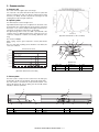
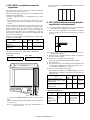
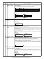
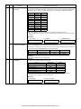
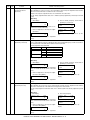
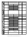
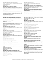
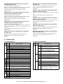
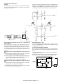
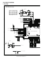
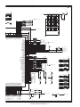
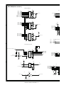
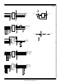
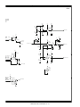
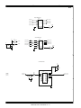
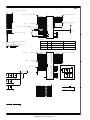
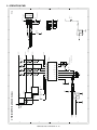
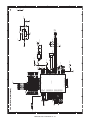
(5) Heater lamp control circuit
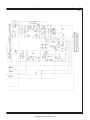
The CPU converts the inputted analog voltage into a digital value. The
digital conversion value and the set value of the test command are
compared to control ON/OFF of the heater lamp according to the level,
controlling the heat roller surface temperature to be the fixed level.
12V
1
3 +
1
MA700
FTH (5-B2)
12V
C110
0.1u
2
R71
4.3kF
4
1
1
2 -
2
R70
10kF
2
R69
1kJ
IC22A
KIA393F
2
2
2
2
8
R68
7.5kF
D1
1
VCC3
1
R67
1MF
1
R66
1kF
1
VCC3
1
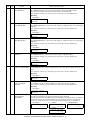
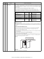
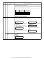
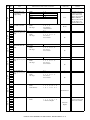
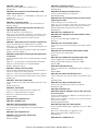
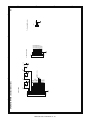
The heater lamp control circuit detects the heat roller surface temperature, and converts the temperature into a voltage. The converted voltage is inputted to the CPU.
2
a. Outline
VCC3
VCC3
D3
D2
1
1
12V
3
3
2
2
8
KDS226
3 +
(11-C1) RTH_IN
KDS226
IC24A
KIA358F
1
1
R81
300J
2
1
R82
100J
RTH (1-A3)
2
12V
4
C111
22000p
1
8
THOPEN (4-A4)
R87
240J
1
R85
10kF
2
1
7
6 -
3
R86
240J
5 +
2
1
1 2
2
4
(11-B2)
(6-A1)
(6-A1)
(6-A1)
(11-B2)
2
PMCLK_A
MRPS_1
MRPS_2
MRPS_3
/LDEN
1
16
15
14
13
12
11
10
9
R84
10kJ
C114
22000p
2
1C
2C
3C
4C
5C
6C
7C
NC
1
1B
2B
3B
4B
5B
6B
7B
G
1
1
2
3
4
5
6
7
8
IC22B
KIA393F
2
1
PMCLK
MRPS1
MRPS2
MRPS3
LDEN
HL
FTH
0.1u
5V
R83
1.2kF
IC26
(1-A2)
(2-C1)
(2-D1)
(2-D1)
(2-C1)
(2-D1)
(5-E3)
12V
C113
2
2
VCC3
1SS355
Q2
KRA119S
C112
0.1u
INT5V
D4
1
1
2 -
2
2
KID65503F
HLOUT (10-B3)
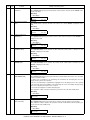
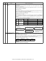
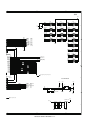
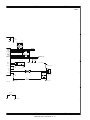
[High temperature protection circuit in case of CPU hung up
(uncontrollable)]
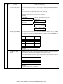
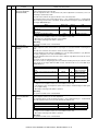
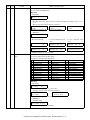
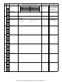
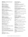
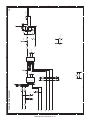
For IC22 3Pin (reference voltage), +3.3V is divided by the resistor. The
thermistor terminal voltage is inputted to IC22 2Pin. When, therefore,
the voltage at 2Pin falls below the voltage at 3Pin, IC22 1Pin becomes
"H" and the HL signal is pulled to the GND level, suppressing generation of the lighting signal of the heater lamp. (IC22 output 1Pin is normally Low.)
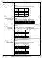
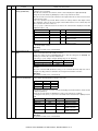
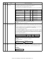
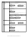
[When the heat roller surface temperature is lower than the set
level]
a. When the thermistor terminal voltage is higher than the set level,
the output signal HL from ASIC becomes HIGH level.
b. This HL signal becomes the HLOUT signal through IC26, and is
inputted to the photo triac coupler in the power PWB. When, therefore, the HL signal is HIGH, the internal triac turns on.
[When the thermistor is open]
The voltage at IC22 6Pin becomes higher than the voltage at 5Pin, and
the 7Pin output THOPEN becomes LOW. This is inputted to the CPU
to display the trouble code H2.
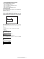
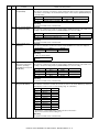
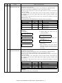
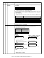
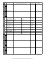
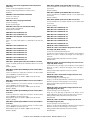
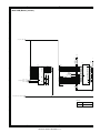
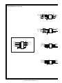
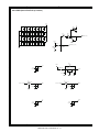
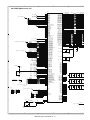
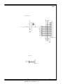
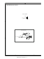
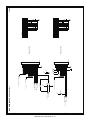
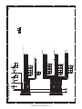
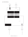
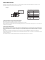
(6) Driver circuit (Clutch, solenoid)
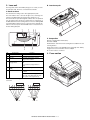
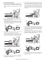
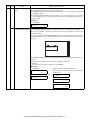
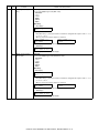
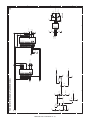
Since a load cannot be directly driven by each load signal from the
CPU or the ASIC, each load is driven through the driver IC (transistor
array).
A large drive current (load current) is ordained from a small input current (ASIC output current).
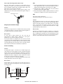
When the driver input voltage (base resistor input) is HIGH, the transistor turns ON to flow a current through the load, operating the load.
+24V
c. When the internal triac turns on, the heater lamp lights up.
[When the heat roller surface temperature is higher than the set
level]
a. When the thermistor terminal voltage falls below the set level, the
output signal HL from ASIC becomes LOW level.
ASIC/CPU
OUT PUT
b. The HL signal becomes LOW, the power PWB photo triac coupler
turns OFF, and the heater lamp turns OFF.
FO-DC550 ELECTRICAL SECTION 13 - 8
LOAD
LOAD