1
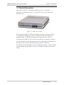
Chapter 2
Installation and Setup
This chapter describes installation and setup procedures for the standalone
ASM-10/8 modem.
ASM-10/8 is delivered completely assembled. It is designed for tabletop or 19-inch
rack installation. For instructions on installation of a single unit or two units in a
19-inch rack, refer to the Rack Mounting Kit for 19-inch Racks guide that comes
with the RM kit.
After installing the unit, refer to Chapter 3 to assure normal operation.
In case a problem encountered, refer to Chapter 4 for test and diagnostic
instructions.
Internal settings, adjustment, maintenance, and repairs may be performed
only by a skilled technician who is aware of the hazards involved.
Always observe standard safety precautions during installation, operation, and
Warning maintenance of this product.
2.1 Site Requirements and Prerequisites
An AC-powered ASM-10/8 should be installed within 1.5m (5 ft) of an easily
accessible grounded AC outlet. The outlet should furnish 115 VAC or 230 VAC
(depending on rated voltage of unit).
A DC-powered ASM-10/8 unit requires DC power supply capable of furnishing
18–60 VDC. In order to prevent a fire hazard, a suitable fuse should be installed in
the DC line.
Allow at least 90 cm (36 in) of frontal clearance for operating and maintenance
accessibility. Allow at least 10 cm (4 in) clearance at the rear of the unit for signal
lines and interface cables.
The ambient operating temperature of ASM-10/8 is 0 to 50°C (32 to 122°F) at
relative humidity of 90%, non-condensing.
2.2 Package Contents
The ASM-10/8 package includes the following items:
• One ASM-10/8 unit
•
Last Mile Access and Intelligent Modems CD
•
AC power cord or DC power supply connector kit
•
RM-17 rack mount kit (if ordered).
Package Contents
2-1