1
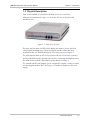
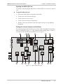
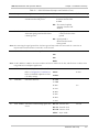
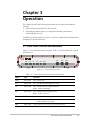
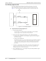
Chapter 3
Operation
This chapter provides the following information for the ASM-10/8 standalone
modem:
•
ASM-10/8 front-panel indicators and controls
•
Operating procedures (turn-on, front-panel indications, performance
monitoring and turn-off).
Installation procedures given in Chapter 2 must be completed and checked before
attempting to operate ASM-10/8.
3.1 Front Panel Controls and Indicators
Figure 3-1 shows the ASM-10/8 front panel. Table 3-1 lists the ASM-10/8 controls
and indicators.
DIG
PWR
RTS
TD
RD
DCD
ANA
REM
TEST
Figure 3-1. ASM-10/8 Front Panel
Table 3-1. ASM-10/8 Front Panel Controls and Indicators
Name
Type
Function
PWR
Green LED
ON – Power is on.
RTS
Yellow LED
ON – The DTE activates Request To Send.
TD
Yellow LED
ON – Steady SPACE is being transmitted.
Blinks – Data is transmitted.
RD
Yellow LED
ON – Steady SPACE is being received.
Blinks – Data is received.
DCD
Yellow LED
ON – A valid receive signal is present.
TEST
Yellow LED
ON – ASM-10/8 is in any of the three loopback modes, or the
PATT pushbutton is pressed.
ERR
Yellow LED
ON or blinks if errors are present in the test pattern.
Front Panel Controls and Indicators
3-1