1
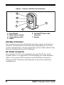
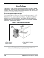
Figure 2. Controls, Indicators and Connectors
A
B
C
E
D
F
A.
B.
C.
D.
Scan Window
Motion Sensor (Inside)
Visual Indicator (LED)
Switch
E. Interface/DC Power cable
connector
F. Speaker
Interface Connector
This connector provides the link between the scanner and the host
terminal. It transmits bar code data and, depending on your host
system configuration, can also supply DC power to the scanner from
the host Terminal (Power-Off-Terminal).
DC Power Connector
The optional AC/DC power adapter provides DC Power to the
scanner, either via a special DC wire extending out of the Interface
cable, or via a special DC connector on the Interface Connector.
The type of DC connector used depends on your host terminal's
configuration.
6
VS800™ Scanner User's Guide