1
STARPLUSTM Triad
Technical Manual
Issue 1 - October, 2001
Part Number: 3050-00
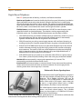
Regulatory Information (U.S.A.)
The Federal Communications Commission (FCC)
established rules to allow the direct connection of the
XTS to a telephone network. Certain actions must be
undertaken or understood before the connection of
customer provided equipment is completed.
Telephone Company Notification
Before connecting the XTS to the telephone network,
the local serving telephone company must be given
advance notice of intention to use customer provided
equipment, and must be provided with the following
information:
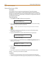
Telephone Numbers
The telephone numbers to be connected to the system.
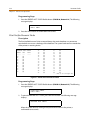
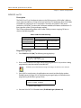
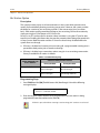
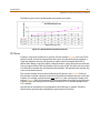
XTS System Information
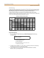
The Ringer Equivalence Number is also located on
the KSU: 1.3B
The USOC jack required for direct interconnection
with the telephone network: RJ11C
FCC Registration Numbers:
For systems configured as a key system: (button
appearances) KF: 5JYKOR-45504-KF-E
For systems configured as a Hybrid system: (dial
access codes) MF: 5JYKOR-45505-MF-E
Incidence of Harm
If the telephone company determines that the customer
provided equipment is faulty and possibly causing harm
or interruption to the telephone network, it should be
disconnected until repairs can be made. If this is not
done, the telephone company may temporarily
disconnect service.
Changes in Service
The local telephone company may make changes in its
communications facilities or procedures. If these
changes affect the use of the XTS or compatibility with
the network, the telephone company must give written
notice to the user to allow uninterrupted service.
Maintenance Limitations
Maintenance on the XTS System must be performed
only by the manufacturer or its authorized agent. The
user may not make any changes and/or repairs except as
specifically noted in this manual. If unauthorized
alterations or repairs are made, any remaining warranty
and the software license for the system will be voided.
Hearing Aid Compatibility
All XTS Digital Terminals are Hearing Aid Compatible, as
defined in Section 68.316 of Part 68 FCC Rules and
Regulations.
UL/CSA Safety Compliance
The XTS System has met all safety requirements and was
found in compliance with the Underwriters Laboratories
(UL) 1459. This system is authorized to bear the “NRTL/C”
marking.
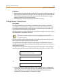
Notice of Compliance
The XTS System complies with rules regarding radiation
and radio frequency emissions by Class A computing
devices. In accordance with FCC Standard 15 (Subpart J),
the following information is supplied to the end user:
“This equipment generates and uses RF energy
and if not installed and used in accordance with
the Instruction Manual, may cause interference to
Radio Communications. It has been tested and
found to comply with the limits for a Class A computing
device, pursuant to Subpart J of Part 15 of the FCC Rules,
which are designed to provide reasonable protection
against such interference, when operated in a commercial
environment. Operation of this equipment in a residential
area is likely to cause interference, in which case the user, at
his own expense, will be required to take whatever
measures may be required to correct the interference.”
Toll Fraud and DISA Disclaimer
“While this device is designed to be reasonably secure
against intrusions from fraudulent callers, it is by no
means invulnerable to fraud. Therefore, no express or
implied warranty is made against such fraud including
interconnection to the long distance network.”
“While this device is designed to be reasonably secure
against invasion of privacy, it is by no means
invulnerable to such invasions. Therefore, no express or
implied warranty is made against unlawful or
unauthorized utilization which results in the invasion of
one’s right of privacy.”
Vodavi has made every reasonable effort to ensure that
this product works in most business environments.
However, there may be some environments (RFI and EFI)
in which this product may not work properly. In such
cases, it is the responsibility of the installer to take the
necessary actions to correct the situation.
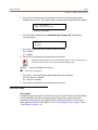
This product is tested and found to be Year 2000 ready.
Vodavi shows 00 as the year in SMDR output and on LCD
displays.
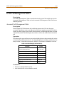
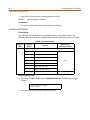
STARPLUSTM Triad
XTS
Digital Key Telephone System
System Programming & Operation
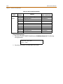
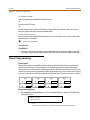
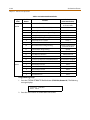
Issue
Release Date
1
10-01
Changes
Initial Release
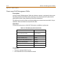
LIFE SUPPORT APPLICATIONS POLICY
VODAVI Technology, Inc. products are not authorized for and should not be used
within Life Support applications. Life Support systems are equipment intended to
support or sustain life and whose failure to perform when properly used in
accordance with instructions provided can be reasonably expected to result in
significant personal injury or death.
VODAVI Technology, Inc. warranty is limited to replacement of defective
components and does not cover injury to persons or property or other consequential
damages.
Copyright © 2001 VODAVI Technology, Inc.
All Rights Reserved
This material is copyrighted by VODAVI Technology, Inc., and may be duplicated by Authorized Dealers only.
Any unauthorized reproductions, use or disclosure of this material, or any part thereof, is strictly prohibited
and is a violation of the Copyright Laws of the United States (17 U.S.C. Section 101 et. seq.).
VODAVI reserves the right to make changes in specifications at any time and without notice. The information
furnished by VODAVI in this material is believed to be accurate and reliable, but is not warranted to be true in
all cases.
STARPLUS, TriadTM, and XTS are registered trademarks of VODAVI Technology, Inc.
mlj/2001
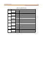
Contents
i
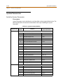
Contents
1
Introduction
General Description ................................................................................................................................ 1-2
System Features ................................................................................................................................ 1-3
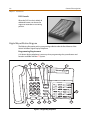
Digital Keyset Telephones ............................................................................................................. 1-4
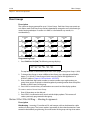
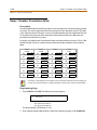
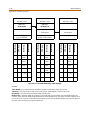
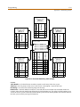
Digital Keyset/Button Diagram .................................................................................................... 1-6
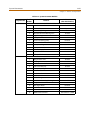
2
Features and Operation
About This Manual .................................................................................................................................. 2-2
Content Summary ............................................................................................................................ 2-2
Manual Format & Description ...................................................................................................... 2-3
911 Feature ................................................................................................................................................ 2-4
911 Attendant Alert ......................................................................................................................... 2-4
Enhanced 911 Integration ............................................................................................................. 2-5
Enhanced 911 Power Failure Station ......................................................................................... 2-6
Account Code ............................................................................................................................................ 2-7
Account Codes - Forced ................................................................................................................. 2-7
Account Codes - Traveling COS (Verified) ................................................................................ 2-9
Initialize Verified Account Code Table ...................................................................................... 2-11
Print Verified Account Codes ....................................................................................................... 2-12
Answering Machine Emulation ........................................................................................................... 2-13
Attendant Assignment / Features ...................................................................................................... 2-14
Automatic Call Distribution (ACD) ..................................................................................................... 2-14
Automatic Privacy .................................................................................................................................... 2-15
Background Music ................................................................................................................................... 2-15
Battery Back-Up (Memory) ................................................................................................................... 2-16
Baud Rate Assignments ......................................................................................................................... 2-16
Cabinet/Card Programming ................................................................................................................ 2-18
Call Back ...................................................................................................................................................... 2-20
Manual Callback ................................................................................................................................ 2-20
Automatic Call Back Timer ............................................................................................................ 2-21
Auto Callback - DSS / BLF ............................................................................................................... 2-21
Message Callback - DSS / BLF Flash Rate .................................................................................. 2-22
Call Coverage ............................................................................................................................................. 2-22
Call Coverage Ring Timer ............................................................................................................... 2-24
Call Forward ............................................................................................................................................... 2-25
Call Forwarding ................................................................................................................................. 2-25
Call Forward - All Calls ..................................................................................................................... 2-26
Call Forward - Busy ........................................................................................................................... 2-27
Call Forward - Busy / No Answer ................................................................................................. 2-28
Call Forward - Follow Me ............................................................................................................... 2-29
Call Forward - No Answer .............................................................................................................. 2-30
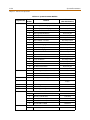
ii
Contents
Call Forward - External (Off-Net) ................................................................................................. 2-31
Call Forward No Answer Timer .................................................................................................... 2-32
Call Forward Button Flash Rate .................................................................................................... 2-32
Call Forward Display ........................................................................................................................ 2-33
Call Forward - Preset ............................................................................................................................... 2-33
Preset Call Forward - Station ........................................................................................................ 2-34
Preset Call Forward - CO Line ....................................................................................................... 2-36
Preset Forward Voice Mail ID ........................................................................................................ 2-37
Preset Forward Timer (Incoming Call to a Destination) ...................................................... 2-38
Preset Forward Timer (Incoming Call to a Station) ............................................................... 2-39
Calling Forward Override ...................................................................................................................... 2-39
Calling Station Handsfree Mode Override ...................................................................................... 2-40
Calling Station Tone Mode Override ................................................................................................. 2-40
Call Park ....................................................................................................................................................... 2-40
Call Park - System .............................................................................................................................. 2-40
Call Park Recall Timer ...................................................................................................................... 2-41
Call Park - Personal ........................................................................................................................... 2-42
Call Park - Station .............................................................................................................................. 2-43
Call Pickup .................................................................................................................................................. 2-44
Directed Call Pickup ......................................................................................................................... 2-45
Group Call Pickup ............................................................................................................................. 2-46
Call Transfer ............................................................................................................................................... 2-46
Ringback on Transfer ....................................................................................................................... 2-48
Unanswered CO Call Transfer ....................................................................................................... 2-48
Calling Station Tone Mode ................................................................................................................... 2-49
Camp On ..................................................................................................................................................... 2-49
Camp On Button Flash Rate .......................................................................................................... 2-50
Camp On Recall ................................................................................................................................. 2-51
Centrex/PBX ............................................................................................................................................... 2-51
CO / PBX Programming .................................................................................................................. 2-51
Off-Hook Preference ........................................................................................................................ 2-52
Private Line Appearance ................................................................................................................ 2-52
Programming ✳, #, and Hook-Flashes into Speed Dial ....................................................... 2-52
Centrex/PBX Flash ............................................................................................................................ 2-53
Centrex/PBX Flash Timer ................................................................................................................ 2-53
Centrex / PBX Transfer .................................................................................................................... 2-54
PBX Dialing Codes ............................................................................................................................ 2-55
Class Of Service ......................................................................................................................................... 2-56
Class of Service - CO Line ............................................................................................................... 2-57
Station Day Class of Service .......................................................................................................... 2-58
Station Night Class of Service ....................................................................................................... 2-59
CO Flexible Port Assignment ............................................................................................................... 2-60
CO Line - Access ....................................................................................................................................... 2-62
CO Line Attributes ................................................................................................................................... 2-63
Initialize CO Line Attributes .......................................................................................................... 2-63
Contents
Print CO Line Attributes ................................................................................................................. 2-65
CO Line DTMF Sending .......................................................................................................................... 2-66
DTMF / Dial Pulse Programming ................................................................................................. 2-66
DTMF On/Off Time Operation ...................................................................................................... 2-67
CO Line Group ........................................................................................................................................... 2-68
Line Group Access - Station .......................................................................................................... 2-68
CO Line Group Programming ....................................................................................................... 2-69
CO Line - Identification .......................................................................................................................... 2-70
CO Line Identification Display ...................................................................................................... 2-70
CO Line - Incoming Ringing Assignment ........................................................................................ 2-72
CO Line Ringing Assignments ...................................................................................................... 2-72
Incoming CO Line Ringing - Setting Flash Rate ..................................................................... 2-74
Display Ring Assignments ............................................................................................................. 2-74
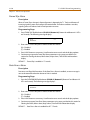
Release Timer ..................................................................................................................................... 2-75
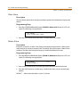
Reseize Timer ..................................................................................................................................... 2-76
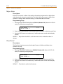
Guard Timer ........................................................................................................................................ 2-77
Seize Timer .......................................................................................................................................... 2-77
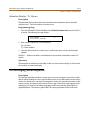
Transmit Volume ............................................................................................................................... 2-78
CO Line Loop and Pool Buttons .......................................................................................................... 2-79
In-Use Hold (I-Hold) Flash Rate .................................................................................................... 2-80
CO Line - Loop Supervision .................................................................................................................. 2-81
Loop Supervision Programming ................................................................................................. 2-81
CO Line - Queue ........................................................................................................................................ 2-82
Line Queuing ...................................................................................................................................... 2-82
CO Line Queue Button Flash Rate ............................................................................................... 2-83
CO Line - Ringing Options .................................................................................................................... 2-84
Transfer CO Ringing ......................................................................................................................... 2-85
Recall CO Ringing ............................................................................................................................. 2-85
Queued CO Ringing Flash Rate .................................................................................................... 2-86
Reminder Ring Timer ....................................................................................................................... 2-86
CO Direction ....................................................................................................................................... 2-87
CO Port Parameters ................................................................................................................................. 2-88
Initialize CO Port Assignments / Flexible Numbering Assignments .............................. 2-88
Print CO Port Parameters and Feature Codes ........................................................................ 2-89
CO Ring Detect Timer ............................................................................................................................. 2-90
Conference ................................................................................................................................................. 2-90
Conference Enable/Disable .......................................................................................................... 2-91
Conference / DISA Timer ................................................................................................................ 2-92
Conference Combinations ............................................................................................................ 2-92
Cordless Key Telephone Unit Feature Button ............................................................................... 2-94
Database Administration ...................................................................................................................... 2-95
Administration Access .................................................................................................................... 2-95
Administration Password ............................................................................................................... 2-96
Database Printout (Dump) ................................................................................................................... 2-97
Dial Pulse Sending ................................................................................................................................... 2-98
iii
iv
Contents
Dial Pulse Parameters ...................................................................................................................... 2-98
Pulse Dial Inter-Digit Timer ........................................................................................................... 2-98
Pulse-to-Tone Switchover ............................................................................................................. 2-99
Direct Inward Dialing .............................................................................................................................. 2-99
DID Phone Number .......................................................................................................................... 2-102
Name Assigned to DID Number .................................................................................................. 2-103
Erasing a DID Table Entry ............................................................................................................... 2-103
DID/ICLID Ringing Assignments .................................................................................................. 2-104
View DID/ICLID Ringing Assignments ....................................................................................... 2-105
DID Digits ............................................................................................................................................. 2-106
DID Incoming Signaling ................................................................................................................. 2-107
DID/TIE Signaling .............................................................................................................................. 2-107
DID Collect Timer .............................................................................................................................. 2-108
Initialize DID-TIE Parameters ........................................................................................................ 2-109
Print DID-TIE Parameters ................................................................................................................ 2-110
Direct Inward System Access (DISA) ................................................................................................. 2-110
DISA Access Code ............................................................................................................................. 2-111
DISA Programming .......................................................................................................................... 2-111
DISA Call Forwarding ....................................................................................................................... 2-112
DISA CO-to-CO ................................................................................................................................... 2-113
Direct Station Selection / Busy Lamp Field ..................................................................................... 2-114
Direct Transfer Mode .............................................................................................................................. 2-115
Directory Dial ............................................................................................................................................. 2-115
Initialize Directory Dial Table Parameters ................................................................................ 2-120
Print Directory Dial Table Parameters ....................................................................................... 2-120
Dial-By-Name ..................................................................................................................................... 2-122
Distinctive Ringing .................................................................................................................................. 2-123
CO Line Distinctive Ring Tone ...................................................................................................... 2-123
Enabling/Disabling Distinctive Ring Tone ............................................................................... 2-124
Ring Tone - Station (User Selectable) ........................................................................................ 2-125
Do Not Disturb .......................................................................................................................................... 2-126
One-Time Do Not Disturb .............................................................................................................. 2-128
Do Not Disturb Button Flash Rate ............................................................................................... 2-128
Do Not Disturb - DSS / BLF Flash Rate ....................................................................................... 2-129
Executive Override .................................................................................................................................. 2-129
Executive Override - Enable/Disable ......................................................................................... 2-129
Executive Override Blocking ......................................................................................................... 2-131
Executive Override Warning Tone .............................................................................................. 2-132
Barge-In Warn Tone ......................................................................................................................... 2-133
Executive / Secretary Pairs .................................................................................................................... 2-134
External Day Ring ..................................................................................................................................... 2-135
External Night Ring ................................................................................................................................. 2-135
Fixed Station/Port Number .................................................................................................................. 2-136
Flash Rates (Programmable) ................................................................................................................ 2-136
Flexible Button Assignment ................................................................................................................. 2-137
Contents
Flexible Button ................................................................................................................................... 2-138
Display Flexible Buttons ................................................................................................................. 2-141
Flexible Numbering ................................................................................................................................ 2-142
Station Port Inquiry .......................................................................................................................... 2-144
Group Listening ........................................................................................................................................ 2-144
Headset Mode ........................................................................................................................................... 2-145
Hold - Exclusive ......................................................................................................................................... 2-146
Exclusive Hold Flash Rate ............................................................................................................... 2-146
Exclusive Hold Recall Timer ........................................................................................................... 2-147
Hold - Preference ..................................................................................................................................... 2-148
Hold - System ............................................................................................................................................ 2-148
System Hold Flash Rate .................................................................................................................. 2-148
System Hold Recall Timer .............................................................................................................. 2-149
Hot Keypad ................................................................................................................................................. 2-149
Hot Line / Ring Down ............................................................................................................................. 2-149
Hunt Groups .............................................................................................................................................. 2-150
Station / Pilot / Pilot All Ring -- Hunting Assignments ........................................................ 2-150
Initialize Hunt Group Parameters ................................................................................................ 2-151
Print Hunt Group Parameters ....................................................................................................... 2-152
Idle Speaker Mode ................................................................................................................................... 2-153
Incoming Calling Line Identification ................................................................................................. 2-153
Intercom ...................................................................................................................................................... 2-153
Intercom Calling ................................................................................................................................ 2-155
Incoming Intercom Ringing Flash Rate .................................................................................... 2-156
Intercom Hold Button Flash Rate ................................................................................................ 2-156
Intercom Signaling Select .............................................................................................................. 2-157
Intercom Transfer ............................................................................................................................. 2-157
Inter-Digit Time-Out ............................................................................................................................... 2-158
ISDN .............................................................................................................................................................. 2-158
Extended Key Telephone Service ............................................................................................... 2-159
Directory Number - BRI ................................................................................................................... 2-160
SPID ........................................................................................................................................................ 2-162
ISDN Programming - Page A ............................................................................................................... 2-163
Basic Rate Interface (BRI) CO Type .............................................................................................. 2-164
Primary Rate Interface (PRI) CO Type ......................................................................................... 2-164
Framing ................................................................................................................................................ 2-165
NT / TE Mode ...................................................................................................................................... 2-165
Power .................................................................................................................................................... 2-166
Directory Number - PRI ................................................................................................................... 2-166
Max Out I-Frames .............................................................................................................................. 2-166
Leading 1 ............................................................................................................................................. 2-167
Leading 011 ........................................................................................................................................ 2-167
7/8 Digit Number Plan .................................................................................................................... 2-168
Calling Number ................................................................................................................................. 2-168
Loopback ............................................................................................................................................. 2-169
v
vi
Contents
10-Digit Number Plan ..................................................................................................................... 2-169
11-Digit Number Plan ..................................................................................................................... 2-170
ISDN Programming - Page B ................................................................................................................ 2-170
Maximum Number Retransmission ........................................................................................... 2-172
Maximum Octets ............................................................................................................................... 2-172
Maximum TEI Request .................................................................................................................... 2-173
Maximum XID Retransmission ..................................................................................................... 2-173
T-200 ...................................................................................................................................................... 2-173
Minimum TEI ID Check Message ................................................................................................. 2-174
Minimum TEI ID Request ................................................................................................................ 2-174
Message Exchange Timer .............................................................................................................. 2-174
Minimum XID Retransmission ...................................................................................................... 2-175
Inter-Digit T / O .................................................................................................................................. 2-175
Set-Up Timer ....................................................................................................................................... 2-176
Disconnect Timer .............................................................................................................................. 2-176
Release Request ................................................................................................................................ 2-177
Link Disconnect ................................................................................................................................. 2-177
Call Proceeding .................................................................................................................................. 2-177
Connect Request ............................................................................................................................... 2-178
Restart Request Timer ..................................................................................................................... 2-178
Initialize ISDN/VoIP Parameters ................................................................................................... 2-179
Print ISDN/VoIP Parameters .......................................................................................................... 2-181
Keyset Mode .............................................................................................................................................. 2-182
Last Number Redial ................................................................................................................................. 2-184
LCD ................................................................................................................................................................ 2-185
LCD Display - Contrast .................................................................................................................... 2-185
LCD Interactive Display .................................................................................................................. 2-185
Least Cost Routing ................................................................................................................................... 2-192
Message Wait ............................................................................................................................................ 2-193
Message Waiting Reminder Tone ...................................................................................................... 2-194
Music-On-Hold .......................................................................................................................................... 2-194
MOH Assignments ............................................................................................................................ 2-194
Music-On-Hold - Enable/Disable ................................................................................................. 2-195
Music-On-Hold (per CO Line) ....................................................................................................... 2-196
Mute Key ..................................................................................................................................................... 2-197
Name In Display ........................................................................................................................................ 2-198
Name / Number Display At Idle ................................................................................................... 2-199
Name / Number Translation Table .................................................................................................... 2-200
Networking Tables .................................................................................................................................. 2-201
Night Service ............................................................................................................................................. 2-202
Automatic / Manual Operation .................................................................................................... 2-202
Day of Week Programming ........................................................................................................... 2-203
Automatic Night Mode Operation ............................................................................................. 2-203
External Night Ringing .................................................................................................................... 2-203
Manual Operation ............................................................................................................................ 2-204
Contents
vii
Night Class of Service (COS) .......................................................................................................... 2-204
Night Ringing Assignments .......................................................................................................... 2-204
Universal Night Answer (UNA) ..................................................................................................... 2-204
Weekly Night Mode Schedule ...................................................................................................... 2-204
Off-Hook Signaling .................................................................................................................................. 2-204
Off-Hook Voice Over ............................................................................................................................... 2-205
Outside Calls .............................................................................................................................................. 2-208
Paging .......................................................................................................................................................... 2-208
Paging Access .................................................................................................................................... 2-210
Paging - Meet Me .............................................................................................................................. 2-211
Paging Time-Out Timer .................................................................................................................. 2-211
Page Warning Tone .......................................................................................................................... 2-212
Paging Zone(s) ................................................................................................................................... 2-212
Pause Timer ................................................................................................................................................ 2-213
Personal Messages .................................................................................................................................. 2-214
Pre-assigned Messages ................................................................................................................... 2-214
Custom Messages ............................................................................................................................. 2-214
Date and Time Entry Messages .................................................................................................... 2-216
Scrollable Canned Messages ........................................................................................................ 2-217
Personal Messages Flexible Button ............................................................................................ 2-218
Preferred Line Answer ............................................................................................................................ 2-219
Privacy Release .......................................................................................................................................... 2-220
Per CO Line Option ........................................................................................................................... 2-220
Per Station Option ............................................................................................................................ 2-222
Private Line ................................................................................................................................................. 2-223
Recall ............................................................................................................................................................ 2-224
Answering a Recall ........................................................................................................................... 2-224
Transfer Recall Timer ....................................................................................................................... 2-224
Repeat Redial ............................................................................................................................................. 2-225
Relay Programming ................................................................................................................................ 2-226
Remote Administration ......................................................................................................................... 2-227
Program Mode Entry ....................................................................................................................... 2-227
Modem Answer Timer ..................................................................................................................... 2-227
Database Upload/Download ........................................................................................................ 2-228
Remote System Monitor And Maintenance ................................................................................... 2-228
Maintenance ....................................................................................................................................... 2-228
Monitor ................................................................................................................................................. 2-228
Ring Down/Hot Line/Off-Hook Preference ..................................................................................... 2-229
Save Number Redial (SNR) .................................................................................................................... 2-232
Serial Number (MPB) ............................................................................................................................... 2-232
Single Line Telephone ............................................................................................................................ 2-233
Compatibility ...................................................................................................................................... 2-233
SLT DTMF Receiver Timer .............................................................................................................. 2-233
SLT Hook Flash Timer ...................................................................................................................... 2-233
SLT Hook Flash Bounce Timer ...................................................................................................... 2-234
viii
Contents
Software Identification (MPB) .............................................................................................................. 2-235
Software Version (MPB) ......................................................................................................................... 2-235
Speakerphone ........................................................................................................................................... 2-236
Speakerphone Options ................................................................................................................... 2-236
Speakerphone Operation .............................................................................................................. 2-237
Speed Dial ................................................................................................................................................... 2-238
Station Speed Dial Numbers ........................................................................................................ 2-238
System Speed Dial Access ............................................................................................................. 2-239
System Speed Bin Access ............................................................................................................... 2-240
Speed Bins/Chaining ....................................................................................................................... 2-241
Initialize System/Station Speed Numbers ............................................................................... 2-241
Print System Speed Numbers ...................................................................................................... 2-242
Station Attributes ..................................................................................................................................... 2-243
Initialize Station Attributes ............................................................................................................ 2-243
Print Station Attributes ................................................................................................................... 2-245
Station Identification .............................................................................................................................. 2-246
Station ID Lock ................................................................................................................................... 2-247
Station Message Detail Recording ..................................................................................................... 2-248
SMDR Enable / Disable .................................................................................................................... 2-250
Long Distance / All Calls ................................................................................................................. 2-251
Character Print Assignment .......................................................................................................... 2-251
Baud Rate Display ............................................................................................................................. 2-251
SMDR Port Assignments ................................................................................................................. 2-252
SMDR Call Qualification Timer ..................................................................................................... 2-252
Station Relocation ................................................................................................................................... 2-253
System Parameters .................................................................................................................................. 2-254
Initialize System Parameters ......................................................................................................... 2-254
Print System Parameters ................................................................................................................ 2-258
System Reset .............................................................................................................................................. 2-260
T-1 Trunking ............................................................................................................................................... 2-260
T-1 Signaling Type ............................................................................................................................ 2-261
T-1 Ringback Option ........................................................................................................................ 2-262
T-1 Dial Tone Option ....................................................................................................................... 2-263
Wink Timer .......................................................................................................................................... 2-263
T-1 Collect Timer ............................................................................................................................... 2-264
T-1 Incoming Signaling ................................................................................................................... 2-265
T-1 Framing Type .............................................................................................................................. 2-265
T-1/ISDN Alarm Programming ............................................................................................................ 2-266
Enable/Disable (Carrier Loss Alarm) ........................................................................................... 2-267
Blue Alarm ........................................................................................................................................... 2-267
Yellow Alarm ...................................................................................................................................... 2-268
Red Alarm ............................................................................................................................................ 2-269
Bipolar Variations Alarm ................................................................................................................. 2-269
Frame Slip Alarm ............................................................................................................................... 2-270
Data Errors Alarm .............................................................................................................................. 2-270
Contents
ix
Clear Alarm .......................................................................................................................................... 2-271
Minor Alarm ........................................................................................................................................ 2-271
Major Alarm ........................................................................................................................................ 2-272
Time Period ......................................................................................................................................... 2-272
Attendant Display - T-1 Alarms .................................................................................................... 2-273
Text Messaging (Silent Response) ..................................................................................................... 2-273
Toll Restriction .......................................................................................................................................... 2-275
Entering Toll Table ........................................................................................................................... 2-278
Allow Table ......................................................................................................................................... 2-279
Deny Table .......................................................................................................................................... 2-281
Special Table ....................................................................................................................................... 2-282
Display Toll Table Entries ............................................................................................................... 2-283
Initialize Exception Tables ............................................................................................................. 2-284
Print Exception Tables .................................................................................................................... 2-285
Toll Restriction Related Items ....................................................................................................... 2-286
Uniform Call Distribution ...................................................................................................................... 2-287
Universal Day/Night Answer ................................................................................................................ 2-287
Universal Day Answer (UDA) ........................................................................................................ 2-288
Universal Night Answer (UNA) ..................................................................................................... 2-289
Voice Mail .................................................................................................................................................... 2-290
Alternate Voice Mail Group ........................................................................................................... 2-291
Leave Mail Index Entry .................................................................................................................... 2-292
Retrieve Mail Index Entry ............................................................................................................... 2-292
Station Assignments ........................................................................................................................ 2-293
VMID Station Numbers ................................................................................................................... 2-293
VM Transfer with ID Digits ............................................................................................................. 2-294
VM Tone Mode Calling Option .................................................................................................... 2-295
Voice Mail ID Translation ................................................................................................................ 2-295
Message Waiting Indication ......................................................................................................... 2-296
Message Wait / VM Button Flash Rate ....................................................................................... 2-296
Voice Mailbox Button ...................................................................................................................... 2-297
Voice Mail Group Button ................................................................................................................ 2-298
Initialize Voice Mail Group Parameters ..................................................................................... 2-298
Print Voice Mail Group Parameters ............................................................................................ 2-299
Voice Mail In-Band Features ................................................................................................................. 2-300
In-Band Signaling Integration ...................................................................................................... 2-300
Voice Mail In-Band Digits ............................................................................................................... 2-301
Voice Mail Transfer / Forward ....................................................................................................... 2-301
Voice Mail Broker .............................................................................................................................. 2-302
Voice Mail ID Digit Length ............................................................................................................. 2-302
Remote Voice Mail Programming ............................................................................................... 2-303
Voice Mail Modem Access ............................................................................................................. 2-303
Voice Mail One-Touch Recording ...................................................................................................... 2-304
One-Touch Recording Warning Tone ....................................................................................... 2-305
Voice Mail Outpulsing Table ................................................................................................................ 2-306
x
Contents
Voice Mail In-Band Signaling ........................................................................................................ 2-306
Voice Mail Disconnect Table ......................................................................................................... 2-308
Voice Over the Internet Protocol ........................................................................................................ 2-308
Volume Control ......................................................................................................................................... 2-309
3
Attendant Features and Operation
Introduction ............................................................................................................................................... 3-3
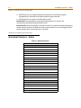
Attendant Features - Index ................................................................................................................... 3-4
911 Attendant Alert ................................................................................................................................ 3-5
Attendant CO Line External (Off-Net) Forward ............................................................................. 3-6
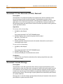
Attendant Custom Message ................................................................................................................ 3-6
Attendant Day/Night/Special .............................................................................................................. 3-8
Attendant Directory List Programming ........................................................................................... 3-8
Attendant Disable Outgoing CO Line ............................................................................................... 3-12
Attendant Override ................................................................................................................................. 3-12
Attendant Setting Time and Date ...................................................................................................... 3-13
Attendant Station Assignment ........................................................................................................... 3-14
Attendant Unavailable ........................................................................................................................... 3-15
Attendant Voice Mail Alarm Clear ...................................................................................................... 3-16
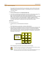
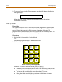
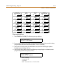
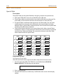
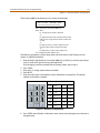
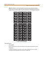
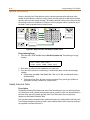
DSS/BLF Console with Map .................................................................................................................. 3-16
Busy Lamp Field Indicators ........................................................................................................... 3-16
Direct Station Calling ....................................................................................................................... 3-16
Mapping Options .............................................................................................................................. 3-16
Transfer Search .................................................................................................................................. 3-21
Station ID for DSS / BLF Console With Map ............................................................................. 3-22
Display Timer ............................................................................................................................................. 3-22
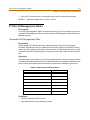
ICLID Call Management Tables ........................................................................................................... 3-23
Answered Call Management Table ............................................................................................ 3-23
Unanswered Call Management Table ....................................................................................... 3-24
Recall ............................................................................................................................................................ 3-24
Attendant Recall Timer ................................................................................................................... 3-25
Release Button .......................................................................................................................................... 3-25
Speed Dial - System Storing ................................................................................................................. 3-26
4
Call Distribution - ACD/UCD
Automatic Call Distribution .................................................................................................................. 4-3
ACD Help .............................................................................................................................................. 4-3
ACD/UCD Calls In Queue Status Display .................................................................................. 4-4
ACD/UCD Available/Unavailable ................................................................................................ 4-6
ACD Call Factor .................................................................................................................................. 4-7
ACD Call Qualifier ............................................................................................................................. 4-7
ACD Member Status ........................................................................................................................ 4-8
ACD Overflow Station Assignment ............................................................................................ 4-9
ACD Overflow Available/Unavailable ........................................................................................ 4-9
Agent Login/Logout ........................................................................................................................ 4-10
Contents
Agent Recall ........................................................................................................................................ 4-11
Alternate ACD Group Assignments ............................................................................................ 4-12
Call Qualifier Tone ............................................................................................................................ 4-12
Calls in Queue Threshold ............................................................................................................... 4-13
Group Name ....................................................................................................................................... 4-13
Guaranteed Message Announcement ...................................................................................... 4-14
Guaranteed Message Timer .......................................................................................................... 4-15
Incoming CO Direct Ringing ......................................................................................................... 4-15
Message Interval Timer ................................................................................................................... 4-15
No-Answer Recall Timer ................................................................................................................. 4-16
No-Answer Retry Timer .................................................................................................................. 4-16
Overflow Station Forwarding ....................................................................................................... 4-17
Overflow Timer .................................................................................................................................. 4-18
PC/ACD Baud Rate Display ............................................................................................................ 4-19
PC/ACD Interface Trace .................................................................................................................. 4-19
PC/ACD Trace Port Assignment ................................................................................................... 4-20
Primary Agents .................................................................................................................................. 4-20
Primary Recorded Announcement ............................................................................................. 4-21
Recorded Announcements ........................................................................................................... 4-21
Recorded Announcement Tables ............................................................................................... 4-22
Ring Timer ........................................................................................................................................... 4-24
Secondary Agents ............................................................................................................................ 4-25
Secondary Recorded Announcement ....................................................................................... 4-25
Supervisor Calls in Queue Status Display ................................................................................. 4-26
Supervisor Login/Logout ............................................................................................................... 4-27
Supervisor Monitor with Barge-In .............................................................................................. 4-28
ACD Supervisor Display .................................................................................................................. 4-29
Supervisor Station Assignment ................................................................................................... 4-30
Transferred Recorded Announcement ..................................................................................... 4-31
Wrap-Up Timer .................................................................................................................................. 4-31
Zap Tone .............................................................................................................................................. 4-32
Initialize ACD Group Parameters ................................................................................................. 4-33
Print ACD Group Parameters ........................................................................................................ 4-34
Uniform Call Distribution ...................................................................................................................... 4-35
UCD Calls In Queue Status Display ............................................................................................. 4-35
Alternate UCD Group Assignments ........................................................................................... 4-36
Incoming CO Direct Ringing ......................................................................................................... 4-36
Message Interval Timer ................................................................................................................... 4-36
No-Answer Recall Timer ................................................................................................................. 4-37
No-Answer Retry Timer .................................................................................................................. 4-38
Overflow Station Assignment ...................................................................................................... 4-38
Overflow Station Forwarding ....................................................................................................... 4-39
Overflow Timer .................................................................................................................................. 4-40
Primary Agent Assignments ......................................................................................................... 4-40
Primary Recorded Announcement ............................................................................................. 4-41
xi
xii
Contents
Recorded Announcements ........................................................................................................... 4-42
Recorded Announcement Tables ............................................................................................... 4-42
Ring Timer ........................................................................................................................................... 4-44
Secondary Recorded Announcement ....................................................................................... 4-45
UCD Available/Unavailable ........................................................................................................... 4-45
UCD Calls In Queue Display .......................................................................................................... 4-46
Wrap-Up Timer .................................................................................................................................. 4-46
Initialize UCD Group Parameters ................................................................................................ 4-47
Print UCD Group Parameters ........................................................................................................ 4-48
A
ICLID / Caller ID
Introduction ............................................................................................................................................... A-3
Functional Performance ........................................................................................................................ A-4
Caller ID Name/Number ................................................................................................................. A-4
Caller ID Name/Number ........................................................................................................................ A-4
Calling Number / Name Display .................................................................................................. A-5
Incoming Number/Name for SMDR Records .......................................................................... A-6
Caller-Entered ICLID Digits ............................................................................................................ A-6
Local Name Translation .................................................................................................................. A-7
ICLID Programming ................................................................................................................................. A-7
Enable / Disable ................................................................................................................................. A-8
Name in Display ................................................................................................................................ A-8
Baud Rate Display ............................................................................................................................. A-8
Port Assignment ................................................................................................................................ A-9
Ring Delay Timer ............................................................................................................................... A-10
Initialize ICLID-DID Tables .............................................................................................................. A-11
Print ICLID - DID Tables ................................................................................................................... A-12
ICLID Call Management Tables ........................................................................................................... A-23
Answered Call Management Table ............................................................................................ A-23
Unanswered Call Management Table ....................................................................................... A-24
B
Least Cost Routing
Introduction ............................................................................................................................................... B-3
LCR Tables ........................................................................................................................................... B-3
LCR Flowchart .................................................................................................................................... B-4
Operation (When LCR is Enabled) ............................................................................................... B-5
Programming LCR Tables ...................................................................................................................... B-5
3-Digit Area / Office Code Table .................................................................................................. B-6
6-Digit Office Code Table ............................................................................................................... B-7
Exception Code Table ..................................................................................................................... B-7
Route List Table ................................................................................................................................. B-8
Insert / Delete Table ......................................................................................................................... B-10
Daily Start Time Table ..................................................................................................................... B-11
Weekly Schedule Table ................................................................................................................... B-12
LCR Routing for Toll Information ................................................................................................ B-14
Contents
xiii
LCR Call Progress ............................................................................................................................... B-14
Default LCR Database ...................................................................................................................... B-15
Forced Least Cost Routing (LCR) ................................................................................................. B-15
LCR Class of Service (COS) ............................................................................................................. B-16
Enable / Disable Least Cost Routing .......................................................................................... B-17
Call Cost Display ................................................................................................................................ B-17
Initialize LCR Tables .......................................................................................................................... B-18
Print LCR Tables ................................................................................................................................. B-19
LCR Printout ........................................................................................................................................ B-20
C
Networking Systems
General Description ................................................................................................................................ C-3
Standards ............................................................................................................................................. C-4
Designing a Network .............................................................................................................................. C-5
Network Termination (NT) ............................................................................................................. C-5
Terminal Equipment (TE) ............................................................................................................... C-5
Connecting to Remote Devices ................................................................................................... C-5
Smart Trunks ....................................................................................................................................... C-5
The Numbering Plan ........................................................................................................................ C-5
Network Installation ................................................................................................................................ C-7
Network Distance ............................................................................................................................. C-7
ISDN and T-1 Clocking .................................................................................................................... C-8
Programming ............................................................................................................................................ C-13
Node/Hub Identification Programming ................................................................................... C-13
Networking Tables Programming .............................................................................................. C-14
Cabinet/Card Programming ......................................................................................................... C-19
Ring Assignment Programming .................................................................................................. C-20
Trunk Direction Programming ..................................................................................................... C-21
T-1 / ISDN Signaling Type Programming ................................................................................. C-23
DID/ICLID Ringing Assignments Programming ..................................................................... C-24
ISDN Programming .......................................................................................................................... C-25
Remote Voice Mail Programming ............................................................................................... C-26
Station User Impacts ........................................................................................................................ C-27
Quick Start Procedure ............................................................................................................................ C-28
Programming ..................................................................................................................................... C-28
D
Voice Over the Internet Protocol
Product Description ................................................................................................................................ D-3
Benefits ................................................................................................................................................. D-3
Specifications ............................................................................................................................................ D-4
Features ................................................................................................................................................ D-4
Installation .................................................................................................................................................. D-5
Hardware Requirements ................................................................................................................ D-5
Network Requirements ................................................................................................................... D-5
System Requirements ..................................................................................................................... D-5
xiv
Contents
Technical Data ................................................................................................................................... D-6
Recommended Bandwidths ......................................................................................................... D-6
Voice Encoder Information ........................................................................................................... D-6
IP Phones ............................................................................................................................................. D-7
Quick Start ........................................................................................................................................... D-8
Programming ............................................................................................................................................ D-9
Identifying the VoIP Card (FLASH 24) ........................................................................................ D-9
Entering Network Programming Requirements (FLASH 46) ............................................ D-10
Setting Up the CO Line Groups (FLASH 40) ............................................................................. D-11
Networking Tables (FLASH 16) .................................................................................................... D-12
Operation .................................................................................................................................................... D-14
Network Connection ....................................................................................................................... D-14
Dialing ................................................................................................................................................... D-14
Line Access .......................................................................................................................................... D-14
IP Telephony Standards and Protocols ............................................................................................ D-15
VoIP Glossary ............................................................................................................................................. D-16
E
Customer Database Programming
Introduction ............................................................................................................................................... E-3
Program Mode Entry (Key Station) .................................................................................................... E-6
Program Mode Entry (Data Terminal or PC) ................................................................................... E-6
Initialization ............................................................................................................................................... E-6
Database Programming Worksheets ................................................................................................ E-7
Database Upload/Download Routine .............................................................................................. E-7
Upload/Download through Remote Administration .......................................................... E-7
Programming Tables .............................................................................................................................. E-12
F
Flash Codes and Numbering Plans
Quick Reference Tables .......................................................................................................................... F-3
Flash Code Index ............................................................................................................................... F-3
Default Numbering Plan ........................................................................................................................ F-16
Part Numbers ............................................................................................................................................. F-20
Figures
xv
Figures
Digital Key Telephone .......................................................................................................................................
Verified Account Codes Printout ...................................................................................................................
CO Line Attributes Printout .............................................................................................................................
Dial Pad Keys ........................................................................................................................................................
CO Port Attributes Printout .............................................................................................................................
DID Name/Number Codes ...............................................................................................................................
DID-TIE Parameters Printout ...........................................................................................................................
Directory List Keypad Map ..............................................................................................................................
Directory Dialing Keypad Map .......................................................................................................................
Directory Dialing Table Printout ....................................................................................................................
Dial-By-Name Keypad Map .............................................................................................................................
Hunt Group Parameters Printout ..................................................................................................................
ISDN/VoIP Attributes Printout ........................................................................................................................
Wiring - Music Source to a CO Line ..............................................................................................................
Name In Display Keypad Map ........................................................................................................................
Other Keypad Codes (Date and Time) .........................................................................................................
Hook Switch Activity ..........................................................................................................................................
System Speed Numbers Printout ..................................................................................................................
Station Attributes Printout ..............................................................................................................................
SMDR Printout ......................................................................................................................................................
System Parameters Printout ...........................................................................................................................
Exception Tables Printout ................................................................................................................................
Voice Mail Group Parameters Printout .......................................................................................................
Directory List Keypad Map ..............................................................................................................................
DSS Console Map #1 ..........................................................................................................................................
DSS Console Map #2 ..........................................................................................................................................
DSS Console Map #3 ..........................................................................................................................................
DSS Console Map #4 ..........................................................................................................................................
DSS Console Map #5 ..........................................................................................................................................
CTI System Configuration ................................................................................................................................
ICLID Translation Tables Printout ..................................................................................................................
DID Translation Tables Printout .....................................................................................................................
LCR Flowchart ......................................................................................................................................................
Daily Start Time and Weekly Schedule Tables ..........................................................................................
Daily and Weekly Start Time Table ...............................................................................................................
Network Configuration Diagram ..................................................................................................................
PRI Connector .......................................................................................................................................................
Point-to-Point PRIs .............................................................................................................................................
TELCO PRI Connection to the Hub ...............................................................................................................
No TELCO Connection .......................................................................................................................................
TELCO PRI Connection To a Node .................................................................................................................
All Systems have TELCO PRI Connection ....................................................................................................
1-6
2-12
2-65
2-71
2-89
2-103
2-110
2-117
2-118
2-121
2-122
2-152
2-181
2-195
2-198
2-216
2-234
2-242
2-245
2-249
2-258
2-285
2-299
3-9
3-17
3-18
3-19
3-20
3-21
A-3
A-13
A-15
B-4
B-12
B-13
C-4
C-8
C-9
C-9
C-10
C-10
C-11
xvi
Figures
All Systems have TELCO T1 Connection .....................................................................................................
Two PRIs from TELCO to Nodes .....................................................................................................................
Two T1s in Hub Connected to PRI in Nodes ..............................................................................................
Two-Node Networking Table Example .......................................................................................................
Five-Node Networking Table Example .......................................................................................................
Bandwidth Consumption by Vocoder .........................................................................................................
Discovery VoIP Card Connection Diagram ...................................................................................................
Data Terminal Program Codes Cross Reference ......................................................................................
Programming Button Mapping .....................................................................................................................
KSU to PC Connection Configuration ..........................................................................................................
C-11
C-12
C-12
C-16
C-17
D-7
D-8
E-4
E-5
E-7
Tables
xvii
Tables
Digital Key Telephone Buttons ......................................................................................................................
Verified Account Code Table Defaults ........................................................................................................
Class of Service (COS) ........................................................................................................................................
Flexible Port Assignments ...............................................................................................................................
CO Line Attribute Defaults ..............................................................................................................................
CO Line Ringing Assignments ........................................................................................................................
DID & ICLID Default Table Entries .................................................................................................................
DID/ICLID Ringing Assignments ....................................................................................................................
DID-TIE Parameter Defaults .............................................................................................................................
CO Line Conference Flag ..................................................................................................................................
Directory Dial Table Defaults ..........................................................................................................................
Ringing Tones ......................................................................................................................................................
Ringing Tones ......................................................................................................................................................
CO Line Barge In Flag ........................................................................................................................................
Flash Rates .............................................................................................................................................................
Hunt Group Defaults ..........................................................................................................................................
ISDN Parameter Defaults ..................................................................................................................................
Liquid Crystal Displays (LCD) ..........................................................................................................................
MOH Programming Codes ..............................................................................................................................
CO Line Privacy Flag ...........................................................................................................................................
Station Privacy Flag ............................................................................................................................................
Station Attribute Defaults ................................................................................................................................
System Parameter Defaults .............................................................................................................................
T-1 Signaling Options ........................................................................................................................................
Class of Service ....................................................................................................................................................
Allow / Deny Table .............................................................................................................................................
Exception Table Defaults .................................................................................................................................
Voice Mail Group Defaults ...............................................................................................................................
Attendant Features ............................................................................................................................................
ICLID Answered Call Management ...............................................................................................................
ICLID Unanswered Call Management ..........................................................................................................
Dial Pad Keys ........................................................................................................................................................
Voice Mail RAN Announcer Options ............................................................................................................
ACD Group Defaults ...........................................................................................................................................
Voice Mail RAN Announcer Options ............................................................................................................
UCD Group Defaults ..........................................................................................................................................
ICLID-DID Table Defaults ..................................................................................................................................
Caller ID Display (Answered Calls) ................................................................................................................
Caller ID Display (Unanswered Calls) ...........................................................................................................
LCR Class of Service Table ................................................................................................................................
LCR Table Defaults ..............................................................................................................................................
Networking Tables - Example 1 .....................................................................................................................
1-7
2-11
2-56
2-60
2-63
2-73
2-101
2-105
2-109
2-113
2-120
2-124
2-125
2-133
2-137
2-151
2-179
2-186
2-197
2-220
2-222
2-243
2-254
2-262
2-276
2-277
2-284
2-298
3-4
3-23
3-24
4-14
4-22
4-33
4-42
4-47
A-11
A-23
A-24
B-9
B-18
C-6
Tables
Networking Tables - Example 2 .....................................................................................................................
TELCO to Hub Interconnect Diagram - Pin Connections ......................................................................
TELCO to Node Interconnect Diagram - Pin Connections ...................................................................
Straight-Through System Interconnect Diagram - Pin Connections ...............................................
CO Line Ringing Assignments ........................................................................................................................
DID/ICLID Ringing Assignments ....................................................................................................................
Bandwidths ...........................................................................................................................................................
VoIP Card Network Programming Requirements ...................................................................................
System Networking Tables ..............................................................................................................................
IP Telephony Standards/Protocols ...............................................................................................................
System Parameters .............................................................................................................................................
Networking Tables (FLASH 16) .......................................................................................................................
Directory Dialing Defaults (FLASH 23) .........................................................................................................
Cabinet/Card Programming (FLASH 24) ....................................................................................................
Hunt Group Parameters (FLASH 30) .............................................................................................................
Verified Account Codes (FLASH 31) .............................................................................................................
CO Line Programming (FLASH 40) ................................................................................................................
Miscellaneous CO Parameters & Timers (FLASH 40/41) ........................................................................
CO Line Ringing Assignments (FLASH 40) .................................................................................................
DID/ICLID Default Ringing Assignments (FLASH 43) .............................................................................
DID Default Table Entry (FLASH 44) .............................................................................................................
Station Programming (FLASH 50) .................................................................................................................
Button Assignment Chart (FLASH 50) .........................................................................................................
Name/Number Translation Table (FLASH 55) ..........................................................................................
System Speed Dial Numbers ..........................................................................................................................
ACD Group Parameters (FLASH 60) ..............................................................................................................
UCD Group Parameters ....................................................................................................................................
Voice Mail Group Parameters .........................................................................................................................
Exception Tables (FLASH 70) ..........................................................................................................................
Least Cost Routing (FLASH 75) .......................................................................................................................
Route List Table ...................................................................................................................................................
Insert/Delete Tables ...........................................................................................................................................
3-Digit Area/Office Code Route List Table .................................................................................................
6-Digit Area Code/Routing Table ..................................................................................................................
6-Digit Office Code Table .................................................................................................................................
Feature Default Values ......................................................................................................................................
XTS System Part Numbers ...............................................................................................................................
xviii
C-6
C-7
C-8
C-8
C-22
C-24
D-6
D-9
D-13
D-15
E-12
E-36
E-37
E-40
E-41
E-42
E-46
E-47
E-48
E-49
E-55
E-59
E-60
E-61
E-64
E-66
E-71
E-72
E-73
E-75
E-76
E-78
E-80
E-81
E-82
F-3
F-20
1
Introduction
This manual provides the information necessary to operate and maintain the XTS
System. The described features are based on the current software release. If any of
these features do not work on your system, call your sales representative regarding
upgrade of your system.
1-2
General Description
Chapter 1 - Introduction
General Description
Allows Flexibility and Software Control
The XTS Digital Key Telephone System is a fully digital hybrid Key Telephone System,
designed to meet the telecommunication needs of medium or large sized business offices.
The system has been designed to allow a high level of software control over the system's
hardware. The software incorporates a vast array of features and capabilities including PC
Database Administration, Auto Route Select, ACD, etc.
The XTS achieves a high level of flexibility by:
Employing a Universal Card Slot architecture with the 1st, the 2nd and 3rd cabinet to
house plug-in Printed Circuit Boards, and
Providing support for different types of instrumentation.
Incorporates Command Processing & Voice Switching
The XTS System incorporates state of the art digital technology for command processing and
voice switching, using a Pulse Code Modulation/Time Division Multiplexing (PCM/TDM, "A"
law or "U" law) distributed switching matrix.
Supports Multiple Devices
The XTS system supports a combination of Digital Keysets, various kinds of ISDN terminals,
and wireless terminals as well as analog single line devices. With the keysets, commonly used
features are activated by direct button selection. Additionally, many functions may be
accessed by dialing specific codes or optionally, by assigning these dial codes to Flexible
Buttons on the keyset. In addition to key telephones, an array of optional terminals is
available including DSS/DLS Console and Intercom.
With the flexibility of the XTS extensive feature content, and the capability to use an array of
instruments, the XTS can be tailored to meet the short and long term needs of the most
demanding customer requirements.
Provides for KSU Expansion
The KSU of the XTS is a wall-mounted cabinet that houses the MB (Mother Board) and card
slots for the CO line/Key Station/SLT/ISDN/LAN interface boards, and other useful boards. The
three-story KSU expansion system allows ample room for future growth.
General Description
1-3
Chapter 1 - Introduction
System Features
This page displays a condensed list of the extensive features available in the XTS System:
911 Feature
Account Codes
Answering Machine Emulation
Attendant Assignment / Features
Automatic Call Distribution (ACD)
Automatic Privacy
Background Music
Battery Back-Up (Memory)
Baud Rate Assignments
Cabinet/Card Programming
Call Back
Call Coverage
Call Forward
Call Forward - Preset
Calling Forward Override
Calling Station Handsfree Mode Override
Calling Station Tone Mode / Override
Call Park - Station
Call Park - System
Call Pickup
Call Transfer
Camp On
Centrex/PBX
Class Of Service (COS)
CO Flexible Port Assignment
CO Line - Access
CO Line Attributes
CO Line DTMF Sending
CO Line Group
CO Line - Identification
CO Line - Incoming Ringing Assignment
CO Line Loop and Pool Buttons
CO Line - Loop Supervision
CO Line - Queue
CO Line - Ringing Options
CO Port Parameters
CO Ring Detect Timer
Conference
Cordless Key Telephone Unit Feature Button
Database Administration
Database Printout (Dump)
Dial By Name
Dial Pulse Sending
Direct Inward Dialing (DID)
Direct Inward System Access (DISA)
Direct Station Selection / Busy Lamp Field
Direct Transfer Mode
Directory Dial
Distinctive Ringing
Do Not Disturb
Executive Override
Executive / Secretary Pairs
External Day Ring
External Night Ring
Fixed Station/Port Number
Flash Rates (Programmable)
Flexible Button Assignment
Flexible Numbering
Group Listening
Headset Mode
Hold - Exclusive
Hold - Preference
Hold - System
Hot Keypad
Hot Line / Ring Down
Hunt Groups
ICLID / Caller ID
Idle Speaker Mode
Incoming Calling Line Identification
Initializing - System Parameters
Intercom
Inter-Digit Time-Out
ISDN / ISDN Programming
Keyset Mode
Last Number Redial
LCD - Contrast
LCD - Display
Least Cost Routing (LCR)
Message Wait
Message Waiting Reminder Tone
Music-On-Hold
Mute Key
Name In Display
Name / Number Translation Table
Networking Systems - Tables
Night Service
Off-Hook Signaling
Off-Hook Voice Over
Outside Calls
Paging
Pause Timer
PBX Dialing Codes
Personal Messages
Preferred Line Answer
Printing - System Parameters
Privacy Release
Private Line
Recall
Repeat Redial
Relay Programming
Remote Administration
Remote System Monitor And Maintenance
Ring Down/Hot Line/Off-Hook Preference
Save Number Redial (SNR)
Serial Number (MPB)
Single Line Telephone (SLT)
Software Identification (MPB)
Software Version (MPB)
Speakerphone
Speed Dial
Station Attributes
Station Identification
Station Message Detail Recording
Station Relocation
Station Speed Dial Numbers
System Parameters
System Reset
System Speed Bin Access
T-1 Trunking
T-1/ISDN Alarm Programming
Text Messaging (Silent Response)
Toll Restriction
Uniform Call Distribution (UCD)
Universal Day/Night Answer
Voice Mail
Voice Mail In-Band Features
Voice Mail One-Touch Recording
Voice Mail Outpulsing Table
Voice Over the Internet Protocol (VoIP)
Volume Control
1-4
General Description
Chapter 1 - Introduction
Digital Keyset Telephones
Each XTS System provides all the keys, indicators, and features described.
Handset and Speaker are located at the left side of the front panel. A handset is provided to
allow confidential conversation when desired. Lifting the handset from its cradle (going
off-hook) disengages the station’s built-in speaker. The speaker is located directly below the
center portion of the handset. The station may be operated with the handset on-hook. When
this occurs, audio is transmitted to the station user through the station’s speaker.
Flexible Buttons provide access to idle outside lines, DSS/BLF for internal stations, access
speed dial numbers and activate features. These buttons can be programmed by the
individual station user. The default flexible feature buttons are described as follows:
»
CALL BACK button lets you initiate a call back request to another busy station. As soon as
that station becomes idle, the station that left the call back request is automatically
signaled. A flexible button must be assigned to use this feature.
»
PICK-UP button lets you pick up a tone ringing intercom call, transferred, incoming, or
recalling outside call to a specific unattended station, by group or directed call pick-up.
»
DND (DO NOT DISTURB) button lets the user place their telephone into Do Not Disturb
mode to eliminate incoming outside line ringing, intercom calls, transfers and paging
announcements. The station in DND can use the telephone to make normal outgoing
calls. On Attendant stations, this button becomes the system Night Mode button. A
flexible button must be assigned to use this feature.
»
LINE QUEUE button lets you queue to an outside line when all lines in a group are busy.
Your station is placed in queue, awaiting a line in the same group to become available.
Outside Calls are announced by a tone signal repeated every 3.2 seconds. The
corresponding outside line indicator flashes slowly.
Intercom Calls can be tone ringing or voice announced. If voice announced, the receiving
station receives three tone bursts prior to the announcement. If a tone ringing call, the
receiving station hears a tone ring every 2.4 seconds.
Enhanced 8-Button Speakerphone
The Enhanced 8-button Digital Telephone is compact in
size with many features normally found only in larger
telephone. The 8 flexible, dual-color LEDs can be
assigned as DSS,CO/PBX/Centrex or feature/function
buttons. When used as DSS buttons, station status can
be seen in a single glance. When used as CO/PBX/
Centrex buttons, line status is easily monitored.
The 4 fixed features include oversized on/off and hold
buttons and fixed volume buttons. The 4 flexible
buttons can be assigned as a CO/PBX line, DSS button,
Speed Dial or Feature button.
To help manage calls more efficiently, this integrated speakerphone has call announce with hands-free
intercom and a hot keypad that allows dialing while the phone is on-hook.
General Description
1-5
Chapter 1 - Introduction
Executive 12-Button Speakerphone
The Executive 12-button Digital Telephone has 12
flexible buttons with dual color LEDs that can be
assigned as DSS, CO/PBX/Centrex or feature/function
buttons. Each flexible button can be assigned as a
CO/PBX line, DSS button, Speed Dial or Feature
button. As DSS buttons, station status can be seen in
a single glance. When used as CO/PBX/Centrex
buttons, line status is easily monitored.
The telephone also features 11 fixed feature buttons
including on/off, mute and hold buttons, speed dial,
message wait, forward and a volume control bar.
Executive 24-Button Speakerphone
The Executive 24-button Digital Telephone has 24
flexible, dual color LEDs that can be customized for
each application.
When the flexible button are used as DSS buttons,
station status can be seen in a single glance. When
they are used as CO/PBX/Centrex buttons, line status
is easily monitored.
This integrated speakerphone offers call announce
with hands-free intercom and a hot keypad that allows
dialing while the phone is on-hook.
Elite 30-Button Large Screen Telephone
The Elite 30-Button Large Screen Display telephone
provides one-touch access to an interactive menu of
commonly used features such as DND, last number
redial, voice mail, speed dial, and call park.
The large display telephone has 11 fixed-feature
buttons and 30 flexible buttons that can be assigned
as CO/PBX/Centrex lines, Station DSS, or feature/
function buttons. This telephone also features an
integrated speakerphone, call announce with
handsfree intercom, a volume control bar, a 7-line by
16-character LCD with 10 softkeys, and long life LEDs.
Additional features include: on-screen name directory, a monthly calendar display, voice mail feature
displays, and 11 message status options.
1-6
General Description
Chapter 1 - Introduction
DSS Console
When the DSS Console is added, 48
additional buttons can be used to
support an attendant or answering
position.
Digital Keyset/Button Diagram
The following illustration and its corresponding table describe the fixed features of the
Vodavi 24-Button Digital Display Telephone.
Programming Requirement
A 24-button display telephone is necessary when programming the system features and
functions available with the XTS System.
12
9
6
2
4
3
1
5
JUL 21 99
STA 153
12:31 pm
VOLUME
SPEED
HTP
abc
def
1
2
3
ghi
jkl
mno
4
5
6
CAMP ON
tuv
wxy
7
8
9
S
oper
prs
0
ON/OFF
10
MSG
CONF
FORWARD
FLASH
16
TRANS
#
MUTE
8
HOLD
13
11
7
15
Figure 1-1: Digital Key Telephone
14
General Description
1-7
Chapter 1 - Introduction
Table 1-1: Digital Key Telephone Buttons
NUMBER
FEATURE BUTTON
FUNCTION
1
Display
(Executive Models only)
Displays information about telephone status, dialing directories, and
text message information.
2
h.t.p.
Used to select mode of operation: Handsfree, Tone, or Privacy.
msg Key
Used for Auto-CallBack to a telephone which has left a text message
or to access voice messages.
4
conf Key
Used to establish conference calls.
5
forward Key
Used to forward your calls to another station or voice mail.
6
speed Key
Used to access speed dialing, save number redial, and last number
redial. This button also is used to access flex button programming.
7
trans Key
Used to transfer an outside call from one station to another.
8
mute Key
Used to activate/deactivate MUTE function. When activated, the
party on the other end cannot hear you.
9
camp-on Key
Used to alert a busy station that an outside line is on hold and
waiting for them.
10
on/off Key
Used to make a call without lifting the handset.
flash Key
Used to end an outside call and to restore dial tone without hanging
up receiver.
volume Key
Used to adjust level of tones, background music, ringing, receiver
volume, and display contrast.
13
hold Key
Used to hold calls, to retrieve held calls.
14
Microphone
Used to talk with other party without using the handset.
15
Speaker
Outputs tones and voice at your extension.
16
Flexible Button Keys
Used to access outside lines or access call-handling features.
3
11
12
»
»
»
»
»
»
»
N O T E S
»
»
»
»
»
»
»
2
Features and Operation
Detailed descriptions of the System and Station features are presented in alphabetical
order. An abbreviated feature index, that is organized in Flash code numerical
sequence, is provided in Appendix F.
2-2
About This Manual
Chapter 2 - Features and Operation
About This Manual
Content Summary
Chapters
The following chapters contain the descriptions, programming steps, and operating
procedures for the more commonly-used features and functions.
2 - Features & Operation
3 - Attendant Features & Operation
4 - Call Distribution - ACD / UCD
Appendices
These Appendix chapters contain detailed information on how to use the more
complex features available.
A - ICLID / Caller ID
B - Least Cost Routing (LCR)
C - Networking Systems
D - Voice Over the Internet Protocol (VoIP)
Worksheets and Tables have been placed at the end of this book for easy access to
specific customer system information and frequently-used flash and feature codes.
E - Customer Database Worksheets
F - Quick Reference Tables
Flash Codes
Default Numbering Plan
Part Numbers
About This Manual
2-3
Chapter 2 - Features and Operation
Manual Format & Description
This diagram explains how the Features/Operations are organized in the following chapters
and appendices. The manual format follows the basic outline as shown, but omits those
elements that do not apply to a particular Feature or Operation.
Feature / Operation
Narrative to explain the feature/operation.
Sub-Feature / Operation
Description
Narrative to explain the sub-feature/operation.
Related Information
Quick Reference
➡ Flash XX
Button X The xxxx function MUST
also be enabled.
Programming Steps
Consists of those actions required of a system
administrator to program single or multiple phones in
the system or system features using a 24-button digital
telephone.
DEFAULT … Shows the system default setting.
Operation
Describes how the user operates the digital telephone.
℡
ELECTRONIC TELEPHONE
When the Electronic Telephone operation differs from
digital, those differences are described.
SINGLE LINE TELEPHONE
When the Single Line Telephone operation differs from
the digital telephone, those differences are described.
Conditions
»
Describes any special criteria that affects the
programming or operation of the feature.
2-4
911 Feature
Chapter 2 - Features and Operation
911 Feature
Description
The 911 Feature allows stations in the system to dial 911 without using an access code. 911
calls are placed on 911 marked lines. If all lines are busy, an existing call is dropped and the
911 call is placed.
When feature is enabled, Trunk Group/LCR Access Code 9 is not available.
Related Information
Quick Reference
➡ Flash 12
To insert [9] for Centrex 911 calls (Refer to “PBX Dialing
Codes” on page 2-55.)
Programming Steps
1. Press the 911 FEATURE flexible button (FLASH 06, Button #13). The following message
displays:
911 FEATURE
DISABLED
0-1
2. Enter a 0 or 1 on the dial pad to enable/disable the use of this feature.
[0] = Disabled
[1] = Enabled
911 Attendant Alert
Description
The 911 Attendant Alert feature allows Attendants with a 911 flexible button to be alerted of
internal stations placing 911 calls. The Attendant can store the sixteen most recent 911 calls.
Calling information includes the time/date of the call as well as the station number that
placed the call.
When the 911 system feature is enabled (FLASH 06), this identifies which CO lines are to be
used for placing 911 calls. The Attendant is alerted via the display and flexible button as to
the time, date, and station number(s) that placed the 911 call.
Lines must be programmed for 911 to enable the 911 feature.
Failure to enable lines for 911 disables 911 calls.
Programming Steps
1. Press FLASH and dial [40]. The following message displays:
CO LI NE AT TRI B UTE S
S EL EC T A CO LI NE R ANG E
911 Feature
2-5
Chapter 2 - Features and Operation
2. Enter a valid number for the range of lines being programmed. If only one line is being
programmed, enter that number twice (001 001).
If HOLD is pressed without entering a CO range, ALL CO lines are selected.
3. Press HOLD to save the entry. A confirmation tone sounds and the display updates.
Flexible button #19 (Page A) is lit. The following message displays to indicate current
programming of that line or group of lines:
XXX - XXX PAG E A
ENTER B UT TO N NUMBER
XXX-XXX = CO Line Range
4. Press FLASH 40, Page A, Button #15 to designate the line for 911 use.
911 TRUNK
DISABLED
0-1
5. Enter a 0 or 1 on the dial pad to enable/disable this feature.
[0] = Disabled
[1] = Enabled
6. Press HOLD to save the entry. A confirmation tone sounds and the display updates.
Operation
Refer to “911 Attendant Alert” on page 3-5.
Enhanced 911 Integration
Description
The E911 feature integrates the system to the Proctor PBX ANI-LINK product to provide
enhanced 911 service. Loop Start lines can be connected to the Proctor unit and
programmed to be 911 lines (FLASH 40, Page A, Button #15). When a 911 call is made from a
station in the system, the system will send 911XXXX (XXXX=Station # that placed the 911 call)
in DTMF format to the Proctor. If the station number is less than 4 digits, a leading 0 will
automatically be added. The Proctor unit then accesses a call trunk and sends the
information in the proper format to the 911 Center.
This feature also provides a means to identify a power failure signal from the Proctor Unit. If a
power failure signal is detected, the KSU routes 911 calls to Trunk Group 1 until the signal is
removed.
2-6
911 Feature
Chapter 2 - Features and Operation
Programming Steps
1. Press the ENHANCED 911 button (FLASH 06, Button #14). The following message
displays:
ENHANCED 911
DISABLED
0-1
2. Enter a 0 or 1 on the dial pad to enable/disable the use of this feature.
[0] = Disabled
[1] = Enabled
Conditions
»
The 911 Feature (FLASH 06, Button #13) must also be enabled for the Proctor Integration
to work.
»
Only the lines connected to the Proctor should have the 911 Enable programmed
(FLASH 40, Page A, Button #15).
»
It is recommended to have a power failure procedure in place to ensure that 911 calls are
always routed. Refer to FLASH 09, Button #7 for programming information.
Enhanced 911 Power Failure Station
Description
The power failure signal is designed to be used with the normally open (NO) power failure
leads from the Proctor unit connected to an SLT port or SLA device. When the leads close in
power failure, this is detected as an off hook and 911 routing ceases to the Proctor unit. 911
calls are sent to Trunk Group 1 until the power failure lead opens, which is detected as an on
hook. 911 calls are then routed again to the Proctor unit.
Programming Steps
1. Press the E911 POWER FAILURE STATION button (FLASH 09, Button #7). The following
message displays:
PRO C TO R 9 11 P/ F
###
100-XXX
2. Enter a valid SLT station number to be used as the power failure station.
3. Press HOLD to save the entry. A confirmation tone sounds.
Conditions
»
»
»
During a power failure, the station’s digits are not sent to Trunk Group 1.
During a power failure, 911 calls are sent on Trunk Group 1.
The feature requires either an SLT port or an SLA port for the integration to work.
Account Code
2-7
Chapter 2 - Features and Operation
Account Code
Description
An account code is the last field within Station Message Detail Recording (SMDR), that
provides tracking capabilities for specific calls by entering a verified/non-verified, variable
length (up to 12 digits) identifier.
The use of forced Account Codes is optional, offered on a system-wide basis. SMDR must be
enabled to use account codes.
Related Information
Quick Reference
➡ Flash 21
Button 1
The SMDR function MUST be enabled (Refer to “SMDR Enable /
Disable” on page 2-250.)
Operation
When connected to an outside line call:
1. Press the preprogrammed ACCOUNT CODE button (feature code 627 - refer to “Flexible
Button Assignment” on page 2-137).
2. Dial account code up to 12 digits. (The other party does not hear the digits being dialed).
If account code is less than 12 digits, an [✳] must be entered to return to the call.
If account codes are forced, the account code must be entered prior to dialing the
outside number.
SMDR must be enabled for the Account Code feature to operate. Also, SMDR
must be enabled for the account code to become part of the SMDR record.
Account Codes - Forced
Description
The XTS allows arranging of the system so that station users must enter an account code
before placing an outside call.
Account codes can also be used as a Traveling Class-of-Service to upgrade a restricted
station’s class-of-service for unrestricted dialing. Account codes must be entered before the
call when forced.
The system can force account codes on all restricted calls.
When the Forced Account Code option is enabled, and the account code is entered, a
station’s Class of Service is upgraded to day COS1, night COS1.
If option is disabled, a station’s COS is not upgraded but the account code continues to be
part of the SMDR record.
2-8
Account Code
Chapter 2 - Features and Operation
Programming Steps
1. Press ACCOUNT CODES flexible button (FLASH 05, Button #8) to determine whether the
use of Account Codes is forced or optional.
2. Enter a 0 or 1 that corresponds with the following entries:
[0] = Disabled
[1] = Enabled
FORCED ACCOUNT CODE
DISABLED
0-1
3. Press HOLD to save the entry. A confirmation tone sounds.
DEFAULT … Account Codes are optional.
Operation
Prior to placing an outside line call:
1. Press the preprogrammed ACCOUNT CODE button.
2. Dial account code up to 12-digits.
SMDR must be enabled for the Account Code feature to operate. Also, SMDR must
be enabled for the account code to become part of the SMDR record. Refer to
“SMDR Enable / Disable” on page 2-250.
SINGLE LINE TELEPHONE
To enter an Account Code before a call:
1. Lift the handset.
2. Dial [627].
3. Dial the account code.
If the account code contains fewer than 12 digits, dial [ ✳] to return to the intercom
dial tone.
4. Dial [9] or CO Access code. Dial tone sounds.
5. Dial the desired number.
To enter an Account Code during a call:
1. Depress the hookswitch momentarily. Your call will be placed on executive hold while
you enter your account code.
2. Dial [627].
3. Dial the account code.
If the account code contains fewer than 12 digits, dial [ ✳] to automatically return to the call.
Account Code
2-9
Chapter 2 - Features and Operation
Account Codes - Traveling COS (Verified)
Description
The Verified Account Code/Traveling Class of Service (COS) feature provides the ability to
track specific calls by entering a verified, variable length (up to 12 digits) identifier. Each
account code can be assigned a day and night Class of Service for determining the dialing
privileges allowed by that account code.
This feature provides a means for users to override a restricted station. If the dialed account
code matches the Verified Account code table, an intercom dial tone is returned, otherwise
an error tone is presented.
Using verified Account Codes is optional, available on a system-wide basis. SMDR must be
enabled for the account code to print as part of the SMDR record. The XTS allows up to 250
12-digit account codes for verification purposes.
✺
ACCT
CODE
1
Q
CLASS OF
SERVICE
2
✺
W
DELETE ACCT
CODE
3
E
✺
✺
5
T
✺
✺
9
O
✺
13
✺
✺
✺
ERASE
DIGITS
4
R
6
Y
✺
7
U
✺
8
I
✺
10
P
✺
11
A
✺
12
S
D
✺
14
F
✺
15
G
✺
16
H
17
J
✺
NEXT
18
K
✺
PREV
19
L
✺
20
;
21
Z
✺
22
X
✺
23
C
✺
24
V
Related Information
Quick Reference
➡ Flash 21
Button 1
The SMDR function MUST be enabled (Refer to “SMDR
Enable / Disable” on page 2-250.)
Programming Steps
To enable or disable Verified Account Codes:
1. Press the VERIFIED ACCT CODES flexible button (FLASH 06, Button #3). The following
message displays:
VERIFIED ACCT CODES
DISABLED
0-1
2. Enter 0 or 1 on the dial pad to enable/disable Verified Account Codes.
[0] = Disabled
[1] = Enabled
3. Press HOLD to save the entry. A confirmation tone sounds.
2-10
Account Code
Chapter 2 - Features and Operation
DEFAULT … Verified Acct Codes are disabled.
To assign Verified Account Codes:
1. Press FLASH and dial [31]. The following message displays:
ACC T
XXXXXXXXXXXX
COS
##
ACCT = Up to 12-digit account code
COS = Class of Service for account codes
2. Press the ACCT CODE flexible button (FLASH 31, Button #1). Enter up to 12 digits (0-9, *,
#). [*] represents a do not care digit. The system ignores all digits after this digit when
entering an account code. The [#] represents a single do not care digit.
3. Press the CLASS OF SERVICE flexible button (FLASH 31, Button #2). Enter a 2-digit Class
of Service Number (1-7) that corresponds to Class of Service 1-7. The first digit represents
Day COS and the second digit represents Night COS.
4. Press HOLD to complete the entry. A confirmation tone sounds.
DEFAULT … No Account Codes are assigned.
To delete the currently displayed Verified Account Code:
1. Press the DELETE CODE flexible button (FLASH 31, Button #3) to delete the entire
account code entry.
2. To display the next account code on the LCD, press the NEXT flexible button (FLASH 31,
Button #18).
3. To display the previous account code on the LCD, press the PREVIOUS flexible button
(FLASH 31, Button #19).
Re-enter the correct digits and press HOLD to complete the entry. A confirmation tone
sounds.
To erase previously entered digits:
1. Press the ERASE DIGITS flexible button (FLASH 31, Button #4)
2. Each press of the button erases one digit. Continue until all desired digits are erased.
3. Re-enter the correct digits, then press HOLD to complete the entry. A confirmation tone
sounds.
Operation
To use Verified Account Codes:
1. Press preprogrammed ACCOUNT CODE button before accessing a CO line.
2. Dial the account code up to 12-digits. If the account code matches a verified account
code, intercom dial tone is returned. Otherwise an error tone is presented.
3. Access the outside CO line or dial the LCR code and dial the desired number.
SMDR must be enabled for the Account Code feature to operate. Also, SMDR must
be enabled for the account code to become part of the SMDR record.
Account Code
2-11
Chapter 2 - Features and Operation
SINGLE LINE TELEPHONE
To enter an Account Code before a call:
1. Lift the handset.
2. Dial [627].
3. Dial the account code.
If the Account Code contains fewer than 12 digits, dial [ ✳] to return to the intercom
dial tone.
4. Dial [9] or CO Access code. Dial tone sounds.
5. Dial the desired number.
Conditions
»
»
Verified Account Codes allow use of an account code as a traveling Class of Service.
»
When verified account codes are activated, station MUST enter an account code to dial a
number that is restricted through station COS and toll restriction. An account code is not
required for calls that are unrestricted through station COS and toll restriction.
»
When verified account codes are not forced, a station user may place a call without
entering an account code. In this case, the station user's COS is based on their station
COS. In this case, a user can enter a verified account code to upgrade their COS.
»
The Redial feature does not support Verified Account Codes.
If LCR is activated in the system and verified account codes are activated, the user must
enter the account code before dialing the LCR code.
Initialize Verified Account Code Table
Description
The Verified Account Code Table may be initialized setting all data fields to their original,
default values.
Table 2-1: Verified Account Code Table Defaults
Program
Code
Flexible
Button
Features
FLASH 31
Default Value
(after initialization)
VERIFIED ACCOUNT CODES
1
Account Code
None
2
Class of Service
None
3
Delete Code
None
4
Erase Digits
None
2-12
Account Code
Chapter 2 - Features and Operation
Programming Steps
1. Press the VERIFIED ACCT CODES flexible button (FLASH 80, Button #14). The following
message displays:
INITIALIZE ACCT
PRESS H OLD
CODES
2. Press the HOLD button. A confirmation tone sounds.
Print Verified Account Codes
Description
The Print Verified Account Codes command dumps the entire database as a permanent
record which can serve as a hardcopy of the database. The system baud rate must match that
of the printer or receiving device.
ACCOUNT CODE TABLE
ENTRY COS
DGTS
----- -----##
00
##
01
##
02
##
03
##
04
##
05
##
06
##
07
##
08
##
09
##
10
11
12
13
14
15
16
17
18
19
20
21
22
23
24
25
##
##
##
##
##
##
##
##
##
##
##
##
##
##
##
26
27
28
29
30
31
32
33
34
35
36
37
38
39
40
... and
##
##
##
##
##
##
##
##
##
##
##
##
##
##
##
so on through 249
Figure 2-1: Verified Account Codes Printout
Programming Steps
1. Press the VERIFIED ACCT CODES flexible button (FLASH 85, Button #15). The following
message displays:
PRI NT ACCT COD ES
PRESS HOLD
2. To print the VERIFIED ACCT CODES, press the HOLD button. The following message
displays:
PRINTING ACCT CO DES
When the system finishes sending the requested information to the printer, a
confirmation tone sounds.
Answering Machine Emulation
2-13
Chapter 2 - Features and Operation
Answering Machine Emulation
Description
When a call is sent to a voice mailbox, the station associated with that can press a
preprogrammed button to listen to the caller leaving the voice mail message. If the mailbox
owner decides to speak with the caller, they can press the preprogrammed button to be
connected to the caller.
Two methods of notification are available, Ring Mode or Speaker Mode. The preprogrammed
button type (654+0=Ring Mode, 654+1=Spkr Mode) defines the operation mode.
EXAMPLE -- Station A places their phone in the answering machine mode by pressing the
flexible button programmed on the telephone. The button light is solid red. Whatever button
type is assigned on the telephone defines the operation mode of the feature.)
When an incoming CO call rings at a station and forwards (except busy type) to the station’s
voice mailbox:
In RING MODE, the preprogrammed answering machine flexible button flashes at
480 ipm red while the caller is in the owner’s mailbox. The mailbox owner presses the
preprogrammed flashing button and the audio is broadcast over the speaker of the
keyset. The mute key is enabled on the keyset at this point. The LED light is solid red.
In SPKR MODE, the voice mail message is broadcast over the speaker. The mute key is
enabled on the keyset and the LED light is solid red.
Display Messages
When a call is ringing the station in ring mode, this message displays:
VM SCREENING RING
MMM DDY Y
HH:MM am
When a station is monitoring the caller in VM, this message displays:
VM SCREENING
MMM DD Y Y
HH:MM am
Answering Machine Emulation only operates on Station Forwarding.
Operation
To set the Operation Mode:
1. Press [SPEED] + [SPEED].
2. Press the desired flexible button for programming.
3. Dial [654] + [0] to select the ring mode or dial [654] + [1] to select the speaker mode.
A confirmation tone sounds.
2-14
Attendant Assignment / Features
Chapter 2 - Features and Operation
The Mailbox Owner has the following options when a call is sent to a voice mailbox:
To leave the caller in the voice mail and stop the speaker broadcast, press the ON/OFF
button. The mailbox owner can continue to listen to the message being left without
taking action at their keyset. When the caller disconnects after leaving the voice mail
message, the button returns to solid red and the keyset returns to idle.
To talk to the party leaving the message, press the MUTE key. The station remains in the
CONF mode, and the caller hears the voicemail and the station user.
To pick up the call, press the flexible button. When the call is picked up, the voice mail
system disconnects from the call, and the voice mail port returns to the idle (waiting)
state. The caller is in a normal talk state with the CO caller.
SINGLE LINE TELEPHONE
Answering Machine Emulation cannot be used with Single Line Telephones.
Conditions
»
»
»
The user must have an Electronic or Digital Keyset.
Keyset must have a preprogrammed ANSWER MACHINE flexible button.
After the in-band digits are sent to the voice mail, the station’s flexible button status is
checked. The feature is executed based on this check. The result of the check is as follows:
Inactive = no feature operation executed
Active = feature executed as per button function (ring mode or speaker mode)
»
An idle station can press the flexible button to go to the inactive mode. The LED
extinguishes and no answer machine calls are presented to the station.
»
»
When button is programmed at the station, it is in the inactive mode (LED extinguishes).
If the station user answers the call, the normal CO line LCD window displays. The call
timer shows the elapsed time including the time the caller was in VM. The call timer does
not start at 0 in this case.
Attendant Assignment / Features
Refer to Chapter 3, Attendant Features and Operation.
Automatic Call Distribution (ACD)
Refer to Chapter 4, Call Distribution - ACD/UCD.
Automatic Privacy
2-15
Chapter 2 - Features and Operation
Automatic Privacy
Description
Privacy is automatically provided on all calls. If one station is conversing, another station
cannot intrude on that line.
The Automatic Privacy feature can be disabled, allowing up to seven other stations to join in
on existing CO line conversations. Refer to “Privacy Release” on page 2-220 for details.
Disabling of the privacy feature may be limited by federal, state or local law, so
check the relevant laws in your area before disabling privacy.
Background Music
Description
Each digital telephone user may receive music over their speaker when an optional music
source is connected to the system. The Background Music feature can be allowed or denied
on a system-wide basis by programming. The system can be programmed to let stations
activate their Background Music, in addition to Music-On-Hold.
Programming Steps
1. Press the BACKGROUND MUSIC flexible button (FLASH 05, Button #6).
2. Enter a valid number (0 or 1) that corresponds with the following:
[0] = Disabled
[1] = Enabled
BACKGROUND MUSIC
ENABLED
0-1
3. Press HOLD to save the entry. A confirmation tone sounds.
DEFAULT … Background Music channel is enabled.
Operation
1. Dial [632] on the dial pad,
-orPress the preprogrammed flexible button.
The LCD display shows the following:
0:OFF
1 /2/3: CH-1/2/3
MMM DD Y Y
HH:MM am
2-16
Battery Back-Up (Memory)
Chapter 2 - Features and Operation
2. Enter the desired channel on the dial pad. Confirmation tone sounds. Music is now issued
through the speaker.
3. Press the Volume Bar to change the volume. The following message displays:
SP EA KER BG M
MMM DD Y Y
[#########]
HH:MM am
SINGLE LINE TELEPHONE
The background music feature is not compatible with single line telephones.
Conditions
»
When you pick up the handset or press the ON/OFF button, music automatically
discontinues.
»
»
When the headset is enabled, BGM discontinues.
A music source must be connected to the BGM/MOH connector.
Battery Back-Up (Memory)
Description
A lithium battery is located on the Main Processing Board (MPB) to protect system memory in
case of commercial power outage or the system power being turned off for a time period.
Battery Back-up Memory retains all system features including system and station speed dial
during a power outage.
Baud Rate Assignments
Description
The System provides outputs such as SMDR or ICLID to the standard RS-232 connectors on
the MPB or RS-232 on the optional SIU Modules.
PORT #1 -- RS-232C port labeled SCMI on the MPB
PORT #2 -- 19.2K modem
PORT #3 and #4 -- RS-232 ports on optional SIU board on MISB.
PORT #5 -- UART on MPB2
PORT #1
MPB RS-232C
1
Q
✺
PORT #2
MODEM
2
✺
PORT #5
UART ON MPB2
5
T
✺
✺
6
W
PORT #3
I/O RS-232
3
✺
Y
✺
7
E
PORT #4
I/O RS-232
4
✺
R
U
✺
I
8
Baud Rate Assignments
2-17
Chapter 2 - Features and Operation
Programming Steps
Press FLASH and dial [15]. The first button is lit and ready for programming Port #1. The
following message displays:
PORT
1
BAUD
19.2K
PORT #1, #3, #4, #5 BAUD RATES
1. Press the desired PORT # flexible button (FLASH 15, Buttons #1, #3, #4, or #5) to
determine the port to program.
2. Enter a 1-digit number for the baud rate:
[1] = 150 Baud
[2] = 300 Baud
[3] = 600 Baud
[4] = 1200 Baud
[5] = 2400 Baud
[6] = 4800 Baud
[7] = 9600 Baud
[8] = 19.2K Baud
3. Press HOLD to save the entry. A confirmation tone sounds and the display updates.
DEFAULT . . . Port #1 = 19.2K, Ports #3, 4, & 5 = 9600.
PORT #2 BAUD RATE
Press the PORT #2 flexible button (FLASH 15, Button #2) to verify the baud rate of the
modem. The following message displays:
PORT
2
DEFAULT . . . Port #2 = 19.2K.
BAUD
19.2K
2-18
Cabinet/Card Programming
Chapter 2 - Features and Operation
Cabinet/Card Programming
Description
The Cabinet/Card Programming feature provides a means to assign the peripheral cards to
alternative peripheral card slots.
Flash 24 also allows for partial signaling over T1IBs (9) or PRIBs (8). For example, card slots
ordinarily accommodate 24 CO line time slots each. This feature allows you to limit the
amount of time slots per card to four (4), or multiples of four (4) up to 20. To use this feature,
the card ID is programmed followed by the number of CO lines to be used in groups of four
(4). A group of four (4) is known as a cluster. If the card number is programmed without a
cluster number, all COs on that card are active.
When using partial signaling, the last channel in the cluster and the 24th channel
are data channels (e.g., for partial signaling with one cluster, the 4th and 24th
channels are data channels. If two clusters are used, then the 8th and 24th channels
are data channels.)
✺
SLOT 0
1
Q
✺
SLOT 1
2
W
✺
SLOT 2
3
E
✺
SLOT 3
4
R
✺
SLOT 4
5
T
✺
SLOT 5
6
Y
✺
SLOT 6
7
U
✺
SLOT 7
8
I
✺
SLOT 8
9
O
✺
10
P
✺
11
A
✺
12
S
✺
13
D
✺
14
F
✺
15
G
✺
16
H
✺
CAB 0
17
J
✺
CAB 1
18
K
✺
CAB 2
19
L
✺
20
;
✺
21
Z
✺
22
X
✺
23
C
✺
24
V
Related Information
Quick Reference
➡ Flash 80
Button #20 System Reset (Refer to “System Reset” on
page 2-260.)
Programming Steps
1. Press FLASH and dial [24]. The following message displays on the display:
C ABINET 0
ENTER B UT TO N NUMBER
Cabinet/Card Programming
2-19
Chapter 2 - Features and Operation
2. Press the button corresponding to the desired cabinet (CAB). Buttons #17-19 represent
cabinets 0-2. The following message displays on the display:
C AB X
DTIB
S LOT
XX
00-14
Button #1 LED is lit to indicate that you are programming for peripheral card slot 0.
3. Press the button corresponding to the desired SLOT location. (Buttons #1-9 indicate
peripheral card slots 0-8.)
Electrical bus configurations restrict the slots that can support T1 and PRI cards
to slots 1-7 of Cabinet 0 and to slots 0-7 of Cabinets 1 and 2.
4. Enter a valid number for the type of card plugged into the current peripheral card slot.
[00] = None
[06] = GCOB
[12] = VOIP
[01] = ETIB
[07] = DIDB
[13] = SL12
[02] = DTIB
[08] = PRIB
[14] = LC08
[03] = DT24
[09] = T1IB
[15] = SI12 (future card)
[04] = SLIB
[10] = BRIB
[16] = LCI8 (future card)
[05] = LCOB
[11] = BR16
5. Enter a valid number (1-5) to specify the desired cluster (partial) quantity.
[1] = cluster of 4
[4] = cluster of 16
[2] = cluster of 8
[5] = cluster of 20
[3] = cluster of 12
No Entry = All CO lines
6. Press HOLD to save the entry. A confirmation tone sounds and the display updates.
7. Press the reset button on the Main Processing Board (MPB).
DEFAULT … Cabinets 0-2 are identified as cabinet 0 and card slots 0-8 are identified as slot 0.
Conditions
»
After programming card slots, a system reset must be performed.
2-20
Call Back
Chapter 2 - Features and Operation
Call Back
The two types of Call Back are Manual Call Back and Automatic Call Back.
Manual Callback
Description
A station can initiate a call back request to another busy station. Once that station becomes
idle, the station that left the call back request is signaled.
The Call Back Button flash rate is the rate at which the Call Back button flashes when a station
at which you left a call back request becomes available. This flash rate can be programmed to
29 different options identified in the flash rate table. This enables the programmer to
customize the key system configuration to desired flash rates.
Programming Steps
1. Press the CALL BACK BTN flexible button (FLASH 07, Button #16). The following
message displays:
C ALL BACK BTN
RED 120 IPM FLASH
00-28
2. Enter a valid number (00-28) on the dial pad to correspond to one of the 29 available
options. (Refer to Table 2-13 on page 2-137.)
3. Press HOLD to save the entry. A confirmation tone sounds and the display updates.
DEFAULT … Call Back Button flash rate is set for a Red 120 ipm Flash (10).
Operation
If you dial a telephone that is busy and want to activate Call Back:
1. Press the CALL BACK button.
2. Hang up.
When the busy station hangs up, you are signaled.
3. Answer the call; station you called is then signaled. (If your station is busy when signaled,
an automatic MSG is left at your phone).
A Call Back Request is automatically invoked anytime a user listens to the
intercom busy tone for a preset period of time.
Only one Call Back request can be left at a station; the second request is converted
to a message wait call back request.
Call Back
2-21
Chapter 2 - Features and Operation
SINGLE LINE TELEPHONE
If you dial a telephone that is busy and want to leave a Call Back indication:
1. Briefly depress and release the hookswitch.
2. Dial [622] and replace the handset.
Only one Call Back request can be left at a station; the second request will convert
to a message waiting request.
Automatic Call Back Timer
Description
The Automatic Call Back Timer invokes a call back anytime a user listens to a busy tone for a
programmable period of time. The Automatic Call Back Timer can be set to 00-99 seconds.
A value of 00 disables the timer. An Automatic Call Back does not occur when the timer is
disabled.
Programming Steps
1. Press the AUTO CALL BACK TIMER flexible button (FLASH 01, Button #17). The following
message displays:
AUTO C ALL BACK
03
00-99
2. Enter a valid number on the dial pad that corresponds to 00-99 seconds in 1-second
increments.
3. Press HOLD to save the entry. A confirmation tone sounds and the display updates.
DEFAULT … Automatic Call Back Timer is set for 03 seconds (enabled).
Auto Callback - DSS / BLF
Description
The Auto Callback DSS/BLF flash rate is the rate at which a DSS button of a station returning
your call back flashes. This flash rate can be programmed to 29 different options identified in
the flash rate table. This enables the programmer to customize the key system configuration
to desired flash rates.
Programming Steps
1. Press the AUTO CBCK – DSS/BLF flexible button (FLASH 07, Button #7). The following
message displays:
AUTO CBCK DSS / BLF
RED 1 20 IPM FLASH
00-28
2. Enter a valid number (00-28) on the dial pad to correspond to one of the 29 available
options. (Refer to Table 2-13 on page 2-137.)
2-22
Call Coverage
Chapter 2 - Features and Operation
3. Press HOLD to save the entry. A confirmation tone sounds and the display updates.
DEFAULT … Auto Callback DSS/BLF flash rate is set for a Red 120 ipm Flash (10).
Message Callback - DSS / BLF Flash Rate
Description
The Message Call Back DSS/BLF flash rate is the rate at which a DSS button of a station
returning your message flashes. This flash rate can be programmed to 29 different options
identified in the flash rate table. This enables the programmer to customize the key system
configuration to desired flash rates.
Programming Steps
1. Press the MSG CBCK / DSS/BLF flexible button (FLASH 07, Button #5). The following
message displays:
MSG CBCK / DSS / BLF
RED 120 IPM FLUT TER
00-28
2. Enter a valid number (00-28) on the dial pad to correspond to one of the 29 available
options. (Refer to Table 2-13 on page 2-137.)
3. Press HOLD to save the entry. A confirmation tone sounds and the display updates.
DEFAULT … Message Callback DSS/BLF flash rate is set for a Red 120 ipm Flutter (11).
Call Coverage
Description
The Call Coverage feature provides the functionality for stations to answer calls for other
stations by utilizing call coverage buttons. Visual and Audible status of ringing stations to an
assigned coverage station are provided. Multiple coverage stations can have the same
remote ringing station(s) programmed on their stations. Once a coverage station answers the
call, other stations attempting to answer the call receive a busy tone and the call coverage
button extinguishes on all appearances of that button.
Direct CO calls have ring and LCD priority over call coverage calls. The call coverage station
must have a direct CO appearance or Loop button in order to pick up an external call. If the
call coverage station is in DND, no audible ringing occurs, however visual and LCD
information is presented.
This feature can be programmed by the station user or through admin programming.
DEFAULT … No call coverage buttons are assigned.
Call Coverage
2-23
Chapter 2 - Features and Operation
Operation
To assign a Call Coverage Button:
1. Press [SPEED] + [SPEED].
2. Press a desired flexible button.
3. Dial [647] for Non-Ringing or [646] for Ringing, followed by the station number to cover. A
confirmation tone sounds.
Once the button is assigned on the station and a call rings in:
1. The coverage station receives audible and/or visual indications for the coverage station
after a programmable period of time. The ring tone is the internal ring tone cadence. The
flash rate is the same as the incoming CO line ringing rate.
Ringing option = ringing, flashing Call Coverage LED, LCD display as in following
illustration.
C A LL FOR S TA XXXX
MMM DD Y Y
HH:MM a m
Non-Ringing option = flashing Call Coverage LED only (no ringing or change to LCD).
2. The Coverage station user then presses their flashing COVERAGE flexible button,
-orPresses the ON/OFF button.
The call is answered and ceases to ring at any other stations that may have the same
coverage appearance. One of the following messages display after the call is answered.
Non-network system or in same Node:
C A LL FOR S TA XXXX
FR O M S TA Y Y Y Y
HH:MM:SS
Network system with call passed across a switch:
XXXXXXXXX C AL LI NG
YYYYYY
HH:MM:SS
XXXXXXXXX = Name of calling party
YYYYYY = Specific CO Line type being used (e.g., PRI #23)
HH:MM:SS = Amount of time on the call
SINGLE LINE TELEPHONE
This feature can cover SLT extensions, however an SLT cannot perform the call coverage
function. The SLT extension need not be physically installed, only the SLT card must be
installed.
2-24
Call Coverage
Chapter 2 - Features and Operation
Conditions
»
Direct CO calls have ring and LCD priority over call coverage calls. The call coverage
station must have a direct CO appearance or Loop button to pick up an external call. If the
call coverage station is in DND, no audible ringing occurs, however visual and LCD
information is presented.
»
This feature can be programmed on any key station or DSS Console with an available
flexible button. If the DSS with a call coverage button assigned is unplugged or moved,
the station associated with that DSS stops ringing until the DSS is plugged in again.
»
»
Camp On or Override drops any internal callers to which a station is talking.
Only one button type (646 or 647) per covered station can be assigned on a keyset.
Call Coverage Ring Timer
Description
A Call Coverage Ring Timer enables the user to set the amount of delay time before the call
coverage feature provides an indication at the coverage station. When that station rings with
an internal or external call, the DSS button for that station rings or flashes. The call coverage
ring timer is a system-wide setting.
The Call Coverage Ring Timer setting is variable from 00-99 seconds. A value of 00 results in
the LED flashing but the call coverage station does not ring.
Programming Steps
1. Press the CALL CVRG RING TIMER flexible button (FLASH 02, Button #3). The following
message displays:
CALL CO VER AGE RING
05
00-99
2. Enter a valid number on the dial pad that corresponds to 00-99 seconds.
3. Press HOLD to save the entry. A confirmation tone sounds and the display updates.
DEFAULT … Call Coverage Ring Timer is set for 5 seconds.
Call Forward
2-25
Chapter 2 - Features and Operation
Call Forward
Description
When any type of station call forwarding is invoked, the LCD display normally indicates the
call forwarding mode at all times. This feature has modified the LCD forwarding display to
make the call forwarding mode display optional. This feature is enabled/disabled in admin
programming on a system-wide basis. The call forward status is stored in a battery protected
area of memory.
Call Forwarding
Description
Stations can be allowed or denied the ability to forward incoming CO calls, intercom calls, or
transferred outside lines to another station or group.
Programming Steps
1. Press FLASH and dial [50]. Flexible button #24 (New Range) is lit and the following
message displays:
STATION AT TRIBUTES
SELECT A STATION R ANGE
2. Enter the range of station numbers to be programmed. If only one station is being
programmed, enter that number twice (100 100).
If HOLD is pressed without entering a station range, ALL stations are selected.
3. Press HOLD to save the entry. A confirmation tone sounds and the display updates.
Flexible button #19 is lit. The display updates to reflect current programming for Page A:
XXX - XXX PAG E A
ENTER BUT TO N NUMBER
XXX-XXX = Station Range
4. Press the CALL FORWARD flexible button (FLASH 50, Page A, Button #10). The following
message displays:
C AL L F OR WARD
ENABLED
0-1
5. Enter a 0 or 1 on the dial pad to enable/disable this feature.
[0] = Disabled
[1] = Enabled
2-26
Call Forward
Chapter 2 - Features and Operation
6. Press HOLD to save the entry. A confirmation tone sounds.
DEFAULT …Call Forwarding is enabled at all stations.
Call Forward - All Calls
Description
The Call Forward All Calls feature allows a station the ability to have all their calls (internal or
external) forwarded immediately to a designated station, an ACD or UCD group pilot
number, Voice Mail group number, or Hunt group.
Operation
To activate All Call Forwarding:
1.
2.
3.
4.
Lift handset or press ON/OFF button.
Press the FWD button or dial [640].
Dial the All Calls code [6].
Press DSS button of desired station,
-orDial the desired extension number where to forward calls, including ACD or UCD, Voice
Mail, Hunt Group pilot numbers and Speed Dial bins for off-net forwarding.
5. Replace handset or press ON/OFF button.
To remove All Call Forwarding:
1. Lift handset or press ON/OFF button.
2. Press the FWD button or dial either [640] or [662]. A confirmation tone sounds and the
FWD LED extinguishes.
SINGLE LINE TELEPHONE
The SLT operation uses the same procedures as used in Digital Telephone operation
described above, except there is no FWD button. The user must use the 640 feature code to
activate and 662 to clear.
Conditions
»
Call Forward remains engaged until manually released. When released, the station
number is returned to the LCD.
»
»
Calls cannot be forwarded to a station in the DND mode.
»
A Forwarded Call signals to the forwarded station in the Tone mode, regardless of the
Intercom Signaling Switch mode selection.
»
»
»
A station in the Forward mode can make outgoing calls.
»
When in All Call Forwarding mode, ACD/UCD calls cannot be received.
CO Line queues, a Message Waiting request, and pre-selected messages are canceled
when a station is placed in the Forward mode.
A Camp On signal is allowed at the forwarded station if that station is busy.
A station denied the use of Call Forwarding receives an error tone when pressing the
CALL FORWARD button.
Call Forward
2-27
Chapter 2 - Features and Operation
»
If a CO Line rings into a station with manual Call Forward, the line sequences to the last
station of the chain. If the last station is in DND mode or does not have a Direct
appearance for the CO Line or a Loop button, the call reverts back to the first station.
»
If a CO Line rings into a station with both Station and Preset Call Forwarding, Station Call
Forwarding takes precedence. Once the Station Forward determines the station to be
rung as per above, preset Call Forward may then apply at the new station.
»
An unlimited number of stations can be set up in a Station Call Forward chain. However, a
station cannot forward to a station that is already a member of their chain.
»
If the last number of the Station Call Forward chain is in DND mode, the internal caller
gets a DND response.
»
»
Calls to a station in both Station Call Forward and DND mode follow the forward.
»
Idle Keyset in hands-free mode does not follow no answer/busy-no-answer forwarding
for internal calls.
If a private line rings into a station with Manual Call Forward the CO Line forwards,
providing the forwarded station has a direct CO Line appearance or an available Loop
button.
Call Forward - Busy
Description
The Call Forward Busy feature allows a station the ability to have their calls forwarded to a
designated station, an ACD or UCD group pilot number, Voice Mail group number, or Hunt
group when their station is busy.
Operation
To activate Busy Call Forwarding:
1.
2.
3.
4.
Lift the handset or press ON/OFF button.
Press the FWD button or dial [640] on the dial pad.
Dial the Call Forward Busy code [8] on the dial pad.
Dial the desired destination number where calls are to be forwarded. A confirmation tone
sounds.
5. Replace handset or press ON/OFF button.
To remove Busy Call Forwarding:
1. Lift handset or press ON/OFF button.
2. Press the FWD button or dial either [640] or [662]. A confirmation tone sounds and the
FWD LED extinguishes.
SINGLE LINE TELEPHONE
The SLT operation uses the same procedures as used in Digital Telephone operation
described above, except there is no FWD button. The user must use the 640 feature code to
activate and 662 to clear.
2-28
Call Forward
Chapter 2 - Features and Operation
Call Forward - Busy / No Answer
Description
The Call Forward Busy/No Answer feature allows a station the ability to forward a
combination busy/no answer calls to a designated station, an ACD or UCD group pilot
number, Voice Mail group number, or Hunt group. No answer calls forward when the
system-wide no answer timer expires. Initial CO ringing, transferred CO ringing and intercom
ringing calls can all be forwarded. Calls that ring to an idle station is call forwarded after
expiration of the No Answer Ring Timer.
Operation
To activate Busy / No Answer Call Forwarding:
1.
2.
3.
4.
Lift the handset or press ON/OFF button.
Press the FWD button or dial [640] on the dial pad.
Dial the Call Forward Busy/No Answer code [9] on the dial pad.
Dial the desired destination number where calls are to be forwarded. A confirmation tone
sounds.
5. Replace handset or press ON/OFF button.
To remove Busy / No Answer Call Forwarding:
1. Lift handset or press ON/OFF button.
2. Press the FWD button or dial either [640] or [662]. A confirmation tone sounds and the
FWD LED extinguishes.
SINGLE LINE TELEPHONE
The SLT operation uses the same procedures as used in Digital Telephone operation
described above, except there is no FWD button. The user must use the 640 feature code to
activate and 662 to clear.
Conditions
»
The user cancels the feature by dialing the Call Forward code or pressing the Call Forward
button again.
»
For Call Forward No Answer, the number of rings before the call is forwarded is
determined by the system-wide Call Forward No Answer timer.
»
Stations Call Forwarded/No Answer forward incoming CO calls according to the Preset
Forward Ring Timer.
»
ICM calls forwarded to a VM group receive ringback until a member of the VM group
becomes available.
»
If a station is denied Station Call Forwarding, then Off-Net Forwarding is not allowed.
Call Forward
2-29
Chapter 2 - Features and Operation
Call Forward - Follow Me
Description
The Follow Me feature lets a user who is away from their station, activate/deactivate call
forwarding from another station in the system. This lets the user forward their calls to their
current location or into Voice Mail, ACD/UCD, Hunt Groups, or to any other station in the
system. When this call forward is activated, all calls presented to the forwarded station
forward to the destination station immediately.
Operation
To activate Follow Me Call Forwarding:
1.
2.
3.
4.
Lift the handset or press ON/OFF button.
Dial the Follow Me Forward code [642] on the dial pad.
Dial station number of the station from which forwarding is desired.
Dial the appropriate forwarding condition code.
[6] = All Calls
[8] = Busy
[7] = No Answer
[9] = Busy/No Answer
5. Dial the three- or four-digit destination number where calls are to be forwarded. (Station,
Voice Mail, ACD/UCD, or Hunt Groups.)
6. Replace handset or press ON/OFF button.
To remove Follow Me Call Forwarding:
1.
2.
3.
4.
5.
Lift the handset or press ON/OFF button.
Dial the Follow Me Forward code [642] on the dial pad.
Dial the station number of the station that forwarding is to be cancelled.
Dial [6] (regardless of the forward condition).
Redial the same station number. Confirmation tone sounds and FWD LED extinguishes.
To establish Follow Me Call Forwarding (off-site location):
1.
2.
3.
4.
Dial into the system on a DISA or TIE trunk. Enter the DISA access code, if applicable.
Dial the Follow Me Forward code [642] on the dial pad.
Dial the station number of the station from which forwarding is desired.
Dial the appropriate forwarding condition code.
[6] = All Calls
[8] = Busy
[7] = No Answer
[9] = Busy/No Answer
5. Dial the three- or four-digit destination number where calls are to be forwarded. (System
Speed Bin, Station, Voice Mail, ACD/UCD, or Hunt Groups.) A confirmation tone sounds;
five seconds later a dial tone is received.
To remove Follow-me Call Forwarding (off-site location):
1.
2.
3.
4.
5.
Dial into the system on a DISA or TIE trunk. Enter the DISA access code, if applicable.
Dial the Follow-Me Forward code [642] on the dial pad.
Dial the station number of the station that forwarding is to be cancelled.
Dial [6] (regardless of the forward condition).
Redial the same station number. Confirmation tone sounds; 5 secs later = dial tone.
2-30
Call Forward
Chapter 2 - Features and Operation
Conditions
»
If a Call Forward mode is currently active at the station where forwarding is desired, the
new forward becomes active and cancels the previous forward.
»
»
»
»
Both internal and external calls to the affected station forward to the designated location.
Call forwarding must be allowed in programming for the affected station.
When remote forward is activated, the forwarding is immediate.
A station’s Call Forward status is stored in a battery protected area of memory. A station’s
Call Forward status is returned after a power failure or system reset occurs.
»
When a key telephone is forwarded remotely, the key station’s forward button lights. The
station user may cancel the forwarding at their station by pressing ON/OFF, then the FWD
button. SLT users can cancel their forwarding by going off hook and dialing the forward
code.
»
DISA callers entering the code and making a mistake are given error tone for 3 seconds,
silence for 2 seconds, then the dial tone is returned.
Call Forward - No Answer
Description
The Call Forward No Answer feature allows a station the ability to have their calls forwarded
to a designated station, an ACD or UCD group pilot number, Voice Mail group number or
Hunt group number when there is no answer at the station. No answer calls forward when
the system-wide no answer timer expires.
Operation
To activate No Answer Call Forwarding:
1.
2.
3.
4.
Lift the handset or press ON/OFF button.
Press the FWD button or dial [640] on the dial pad.
Dial the Call Forward No-Answer code [7] on the dial pad.
Dial the desired destination number where calls are to be forwarded. A confirmation tone
sounds.
5. Replace handset or press ON/OFF button.
To remove No Answer Call Forwarding:
1. Lift handset or press ON/OFF button.
2. Press the FWD button or dial either [640] or [662]. A confirmation tone sounds and the
FWD LED extinguishes.
SINGLE LINE TELEPHONE
The SLT operation uses the same procedures as used in Digital Telephone operation
described above, except there is no FWD button. The user must use the 640 feature code to
activate and 662 to clear.
Call Forward
2-31
Chapter 2 - Features and Operation
Call Forward - External (Off-Net)
Description
Stations are allowed to forward intercom and transferred CO line calls to an off-net location.
The Call Forward Off-Net feature allows a station to reroute calls that would normally be lost.
Calls can be forwarded to home or another off-net site. Initially ringing CO calls cannot be
forwarded with this feature.
Operation
To activate Off-Net Call Forwarding:
1. Lift handset or press ON/OFF button.
2. Press the FWD button or dial [640] on the dial pad.
3. Dial [✳] on the dial pad. Dial the speed bin number (9000-9019 or 9020-9999) that
contains the number where calls are to be forwarded. A confirmation tone sounds and
the FWD button LED is flashing.
4. Replace handset or press ON/OFF button.
To remove Off-Net Call Forwarding:
1. Lift handset or press ON/OFF button.
2. Press the FWD button or dial either [640] or [662]. A confirmation tone sounds and the
FWD LED extinguishes.
SINGLE LINE TELEPHONE
The SLT operation uses the same procedures as used in Digital Telephone operation
described above, except there is no FWD button. The user must use the 640 feature code to
activate and 662 to clear.
Conditions
»
»
The user cancels forwarding by going off-hook and pressing the FWD button.
»
The call to a station is not answered until the outgoing CO Line is seized and the digits are
out-pulsed. The calling Station receives ICM ringback until answered. Upon answer the
Station receives whatever CO progress tones apply (Ringback, Busy, Error,
Announcement, etc.).
»
»
»
If a station is denied Station Call Forwarding, Off-Net forwarding is not allowed.
»
»
SMDR printout reflects transferred and outgoing calls like a DISA call record.
»
Call must be an intercom or transferred CO call.
Forwarding is unconditional and occurs immediately when a station calls an Off-Net
forwarded station.
Toll Restriction is based on the forwarding station’s COS and the outgoing CO Line COS.
The calling station must have an appearance (Direct, Loop) for the outgoing (Off-Net)
line. The call is not forwarded if a Direct Appearance or LOOP key is unavailable.
Station users may use Station or System Speed Dial as the Speed Dial Bin used for Station
Off-Net Forward.
2-32
Call Forward
Chapter 2 - Features and Operation
Call Forward No Answer Timer
Description
The Call Forward No/Answer Timer is used when a station in the system specifies that no
answer calls be forwarded to another station. The timer determines how long an intercom or
transferred call rings before it is considered a no-answer call.
The call then forwards to the designated station for handling. The Call Forward No/Answer
Timer setting is variable from 000-600 seconds.
Initial incoming CO lines follow the Preset Call Forward Timer when encountering a
station in the Forward / No Answer mode.
Programming Steps
1. Press the CALL FORWARD NO ANSWER TIMER flexible button (FLASH 01, button #6). The
following message displays:
C AL L FWD NO A NS
015
000-600
2. Enter a valid number on the dial pad that corresponds to 000-600 seconds.
3. Press HOLD to save the entry. A confirmation tone sounds and the display updates.
DEFAULT … Call Forward No/Answer Timer is set for 15 seconds.
Call Forward Button Flash Rate
Description
The Call Forward Button flash rate is the rate at which the Call Forward button flashes when
any type of forward mode is used. This flash rate can be programmed to 29 different options
identified in the flash rate table. This enables the programmer to customize the key system
configuration to desired flash rates.
Programming Steps
1. Press the CALL FORWARD BTN flexible button (FLASH 07, Button #3). The following
message displays:
C A L L F O R WA R D BT N
RED S TEADY O N
00-28
2. Enter a valid number (00-28) on the dial pad to correspond to one of the 29 available
options. (Refer to Table 2-13 on page 2-137.)
3. Press HOLD to save the entry. A confirmation tone sounds and the display updates.
DEFAULT … Call Forward Button flash rate is set for a Red Steady On (01).
Call Forward - Preset
2-33
Chapter 2 - Features and Operation
Call Forward Display
Description
When call forwarding is invoked, the LCD display normally indicates the call forwarding mode
at all times.
This feature is enabled/disabled in administrative programming on a system-wide basis.
Programming Steps
1. Press the CALL FWD DISPLAY STATUS flexible button (FLASH 06, Button #4). The
following message displays:
C AL L F WD DI S PL AY
ENABLED
0-1
2. Enter a 0 or 1 on the dial pad to enable/disable Call Forward Display.
[0] = Disabled
[1] = Enabled
3. Press HOLD to save the entry. A confirmation tone sounds.
DEFAULT … Call Forward Display is enabled.
Call Forward - Preset
Description
The Call Forward Preset feature allows the system database to be configured so that
incoming CO Lines, which are programmed to ring at a particular station, can be forwarded
elsewhere in the system predetermined by programming. This feature is active if the station
ringing is not answered in a specified time, and is particularly useful in overflow applications
in which a Voice Mail or Auto Attendant may be in use.
A station may have one designated preset forward location defined in the database.
Each station in the system may, independently, have incoming CO calls preset forwarded
to the following destinations:
Preset Call Forward - ACD, Voice Mail, UCD, or Hunt Groups -- CO Lines can be Preset
Forwarded to ring to one of the group types in the system (ACD, Hunt Voice Mail, or UCD).
CO lines do not Preset Forward to a busy ACD Group. Each time the Preset Forward Timer
expires (a total of 5 attempts), the group is checked for an idle station.
Preset Call Forward - Off-Net -- CO Lines can be preset forwarded to ring Off-Net via
speed dial from any station. After the expiration of the preset forward timer, the system
selects an idle CO line and dial the off-net location, then connect the two CO lines.
2-34
Call Forward - Preset
Chapter 2 - Features and Operation
Preset Call Forward - Per CO Line -- The Preset Call Forward feature allows each CO line
to be preset call forwarded on a per CO line basis. This allows a CO line to initially ring at
multiple stations and forward to a predetermined destination. The destination can be a
station or Hunt Group. Each CO line has a Preset Forward Timer. Each CO line also has a
VMID field to allow specific VM digits to be sent when a CO line forwards to a VM group.
Feature applies to initial CO ringing lines only.
If a forward destination is programmed in the CO line field, the CO call forwards to
that destination after the CO Preset Forward timer expires. This forward occurs
regardless of how many or how few stations the line is ringing on. Once the CO line is
answered and transferred, station call forwarding rules are in effect.
Calls still follow all call or busy forwards, however, CO preset forward forwards the call
if the first forward destination has not answered the call. VMID digits per CO line
override station VMID. Calls ringing into ACD, UCD or VM Groups continue to ring the
group. The CO call does not forward when ringing one of these types of groups.
Preset Call Forward - Stations -- Each station user may have Preset Call Forward in the
database to direct incoming, transferred, as well as intercom calls to other destinations in
the system. The system allows for different destinations based on a Busy or a No Answer
condition, as wells as internal versus external (CO) call.
Preset Call Forward - Station
Description
The Preset Call Forward feature provides separate Busy and No Answer destinations for
internal and external calls with a No Answer Timer associated to each station. External calls
ringing that particular station, transferred calls, and internal calls follow this Preset Forward
feature.
Programming Steps
To program internal and external calls with separate Busy and No Answer destinations,
perform the following steps.
Valid destination entries are:
9020-9999 = Speed bins
100-195 = Station Numbers (MPB1)
100-351 = Station numbers (MPB2)
440-447 = Voice mail groups
450-457 = Hunt groups
550-565 = ACD groups
1. Press FLASH and dial [50]. Flexible button #24 (New Range) is lit and the following
message displays:
STATION AT TRIBUTES
SELECT A STATION R ANGE
Call Forward - Preset
2-35
Chapter 2 - Features and Operation
2. Enter the range of station numbers to be programmed. To program only one station,
enter the number twice (100 100).
If the HOLD button is pressed without entering a station range, ALL stations are
selected.
3. Press HOLD to save the entry. A confirmation tone sounds and the display updates.
Flexible button #19 (Page A) is lit.
4. Press button #21. The display updates to reflect current programming for Page C.
XXX-XXX PAG E C
ENTER B UT TO N NUMBER
XXX-XXX = Station Range
Internal No Answer Destination
1. Press FLASH 50, Page C, Button #1. The following message displays:
INTERNAL NO ANSWER FWD
####
2. Enter a valid destination number and press HOLD.
3. To delete the entry, press the [#] key and then press HOLD.
Internal Busy Destination
1. Press FLASH 50, Page C, Button #2. The following message displays:
INTERNAL B USY FWD
####
2. Enter a valid destination number and press HOLD.
3. To delete the entry, press the [#] key and then press HOLD.
External No Answer Destination
1. Press FLASH 50, Page C, Button #3. The following message displays:
EX TERNAL NO A NSWER FWD
####
2. Enter a valid destination number and press HOLD.
3. To delete the entry, press the [#] key and then press HOLD.
2-36
Call Forward - Preset
Chapter 2 - Features and Operation
External Busy Destination
1. Press FLASH 50, Page C, Button #4. The following message displays:
EX TERNAL BUSY FWD
####
2. Enter a valid number and press HOLD.
3. To delete the entry, press the [#] key and then press HOLD.
No Answer Timer
1. Press FLASH 50, Page C, Button #5. The following message displays:
NO ANSWER TIMER
10
00-99
2. Enter a valid number (00-99) and press HOLD (00=disable).
DEFAULT … No Answer Timer is set at 10 seconds.
Conditions
»
Station Forwarding overrides the Preset Forward settings.
Preset Call Forward - CO Line
Description
The Preset Call Forward Destination feature enables a CO line to initially ring at multiple
stations and forward to a pre-determined destination. The destination can be a station
(EKT-SLT) or Hunt group. Each CO line has a Preset Forward Timer. Each CO line also has a
VMID field to allow sending of specific VM digits when a CO line forwards to a VM group. Calls
ringing into ACD/UCD Groups or Voice Mail Groups continue to ring the group. The CO line
does not forward when ringing one of these types of groups.
Programming Steps
1. Press FLASH and dial [40]. The following message displays:
CO LINE AT TRIBUTES
SELECT A CO LINE R A NGE
2. Enter a valid number for the range of lines being programmed. If only one line is being
programmed, enter that number twice (001 001).
If HOLD is pressed without entering a CO range, ALL CO lines are selected.
3. Press HOLD to save the entry. A confirmation tone sounds and the display updates.
Flexible Button #19 (Page A) is lit.
Call Forward - Preset
2-37
Chapter 2 - Features and Operation
4. Press the Page B flexible button (Button #20). The following message displays:
XXX - XXX PAG E B
ENTER B UT TON NUMBER
XXX-XXX = CO Line Range
5. Press the PRESET FWD DESTINATION flexible button (FLASH 40, Page B, Button #5). The
following message displays:
PRESET FOR WARD D EST
####
6. Enter a valid forward destination on the dial pad.
[9020-9999] = System Speed Bins
[100-351] = Station Extensions
[440-447] = Voice Mail Groups 1-8
[450-457] = Hunt Groups 1-8
[550-557] = UCD Groups 1-8
[550-565] = ACD Groups 1-6
7. A confirmation tone sounds and the LCD display updates.
DEFAULT … No destinations are assigned.
Preset Forward Voice Mail ID
Description
The Preset Forward Voice Mail ID feature allows a programmer to assign which digits are sent
to voice mail when a CO line is programmed to Preset Forward.
Programming Steps
1. Press the PRESET FWD VMID flexible button (FLASH 40, Page B, Button #6). The
following message displays:
PRE S ET FOR WARD VMID
####
0000-9999
2. Enter a valid number on the dial pad that corresponds to 0000-9999 for Voice Mail ID
digits.
3. Press HOLD to complete the entry. A confirmation tone sounds and the display updates.
To delete numbers currently entered:
1. Press [#] button four times.
2. Press the HOLD button to update. (All information is erased.)
DEFAULT … No digits are sent.
2-38
Call Forward - Preset
Chapter 2 - Features and Operation
Preset Forward Timer (Incoming Call to a Destination)
Description
The Preset Forward Timer determines the time an outside line rings before being forwarded
to a predetermined destination as programmed in FLASH 50, Page C, Buttons 1-4. If a forward
destination is programmed in the CO line field, the CO calls forward to that destination after
the CO preset forward timer expires. This forward occurs regardless of how many stations the
line is ringing.
The digits entered for the CO line are sent in the station field.This feature applies to initial CO
ringing lines only and works with Preset Forward CO Line assignments. The CO Line Preset
Forward Timer setting is variable from 00-99 seconds. A [00] entry disables the timer and the
feature is disabled.
Programming Steps
1. Press FLASH and dial [40]. The following message displays:
CO LI NE AT TRI B UTE S
S EL EC T A CO LI NE R ANG E
2. Enter a valid number for the range of lines being programmed. If only one line is being
programmed, enter that number twice (001 001).
If HOLD is pressed without entering a CO range, ALL CO lines are selected.
3. Press Button #21 to select Page C. The display updates. The following message displays to
indicate current programming of that line or group of lines:
XXX - XXX PAG E C
ENTE R B UT TON NUMB ER
XXX-XXX = CO Line Range
4. Press the PRESET FWD TIMER flexible button (FLASH 40, Page C, Button #8). The
following message displays:
PRE SE T FWD TI MER
10
00-99
5. Enter valid number on dial pad which corresponds to 00–99 seconds.
6. Press HOLD to save the entry. A confirmation tone sounds and the display updates.
DEFAULT … CO Line Preset Forward Timer is set at 10 seconds.
Calling Forward Override
2-39
Chapter 2 - Features and Operation
Preset Forward Timer (Incoming Call to a Station)
Description
The Preset Forward Timer determines the time an outside line rings before being forwarded
to a predetermined station within the local system. This entry works with Preset Forward
station assignments in Station Programming. More than one station can be forwarded to the
same party.
Initial incoming CO lines follow the Preset Call Forward Timer when encountering
a station in the Forward/No Answer mode.
This timer also governs the time the DISA call rings at a station before returning to intercom
dial tone, if not answered. The Preset Forward Timer setting is variable from 01–99 seconds.
Programming Steps
1. Press the PRESET FORWARD TIMER flexible button (FLASH 01, Button #5). The following
message displays:
PRESET FWD TIMER
10
00-99
2. Enter a valid number on the dial pad that corresponds to 01-99 seconds.
3. Press HOLD to save the entry. A confirmation tone sounds and the display updates.
DEFAULT … Preset Forward Timer is set at 10 seconds.
Conditions
»
If no preset forward destination is programmed, the feature is disabled.
Calling Forward Override
Description
The Call Forward Override feature allows a user to reach a busy station that is call forwarded.
This allows the calling station to override the forwarding which allows the user to use Off
Hook Voice Over (OHVO), Executive Override, Monitor, Message Wait Indication, Camp On, or
Call Back Request at that station rather than forwarding to another destination.
Operation
1. Dial [5#] followed by the desired station extension.
2. Press the appropriate preprogrammed button.
Call Back = [622]
Camp On = [620]
Executive Override = [625]
Message Wait = [623]
OHVO = [628]
2-40
Calling Station Handsfree Mode Override
Chapter 2 - Features and Operation
Calling Station Handsfree Mode Override
Description
Enables a calling station to override a called station’s T intercom setting.
Operation
When placing a call to a station and handsfree is desired:
1. Dial [7#] on the dial pad.
2. Dial the extension number,
-orPress DSS button of desired station (call tone rings station).
Calling Station Tone Mode Override
Description
Enables a calling station to override a called station’s H or P intercom settings.
Operation
When placing a call to a station and tone ringing is desired:
1. Dial [6#] on the dial pad.
2. Dial the extension number,
-orPress DSS button of desired station (call tone rings station).
Call Park
Call Park - System
Description
An outside line can be placed into one of eight parking locations and can be retrieved by any
station that has a direct line appearance or an available Loop button. Parked calls have their
own recall timer that recalls the originating station, and if still unanswered, the Attendant(s).
An outside line may also be placed into a station park location. The station user then dials a
code followed by their station number to retrieve the call.
Operation
To consult, page, or call an internal party while connected to an outside line:
1. Press TRANS button or press the CALL PARK flexible button. The caller is put on hold.
2. Dial parking location (430 to 437) or press the preprogrammed CALL PARK flexible
button. A confirmation tone sounds.
Call Park
2-41
Chapter 2 - Features and Operation
3. If busy tone is received, press TRANS twice and dial another park location or press the CALL
PARK flexible button for a different parking location.
Call Park Pickup - System
To retrieve a Parked Call:
1. Lift handset or press ON/OFF button.
2. Press the [#] button.
3. Dial parking location (430 to 437) where the call was parked or press the preprogrammed
CALL PARK flexible button.
SINGLE LINE TELEPHONE
To place an outside call on hold and consult with, page, or call an internal party before
transferring the outside call:
1. Depress and release the hookswitch. The caller is put on Exclusive Hold.
2. Dial parking location (430 to 437). A confirmation tone sounds.
3. If busy, depress and release hookswitch twice, dial another park location, then hang up.
To retrieve a parked call:
1. Lift the handset.
2. Press the [#] button.
3. Dial parking location (430 to 437) where the call was parked.
Call Park Recall Timer
Description
The Call Park Recall Timer determines the time before a call placed in a Call Park location
recalls the station placing the call in park. If unanswered by that station, the call recalls the
attendant.
The Call Park Recall Timer setting is variable from 000–600 seconds. A 000 entry disables the
timer and there is no recall.
Programming Steps
1. Press the CALL PARK RECALL TIMER flexible button (FLASH 01, Button #8). The following
message displays:
C AL L PARK TIME R
180
000-600
2. Enter a valid number on the dial pad that corresponds to 001-600 seconds.
3. Press HOLD to save the entry. A confirmation tone sounds and the display updates.
DEFAULT … Call Park Recall Timer is set at 180 seconds.
2-42
Call Park
Chapter 2 - Features and Operation
Call Park - Personal
Description
Each digital telephone in the system can place a call into a personal park location and then
later retrieve that call from the originating station. Intercom calls and CO line calls can be
placed into the stations’ personal park location. Calls parked in a personal park location are
subject to the system call park recall timer (refer to “Call Park Recall Timer” on page 2-41. A
station retrieving a personal parked CO call must have either a direct CO line appearance or
an available loop button to retrieve the parked call.
Only one call can be parked in a Personal Call Park location at one time. When
dialing the Personal Park location and the location is already occupied, the
initiating station receives the previously parked call and the second call is then
parked.
Operation
To park a call, while connected to an outside line:
1. Press the TRANS button. The caller is put on Exclusive Hold.
2. Dial the Personal Park location [438] on the dial pad,
-orPress the preprogrammed PERSONAL PARK button. Dial tone sounds.
To retrieve a parked call:
Dial the Personal Call Park location code [438] on the dial pad,
-orPress the preprogrammed PERSONAL PARK button. A talk path is established between the
two parties.
SINGLE LINE TELEPHONE
While connected to first call:
1.
2.
3.
4.
5.
Depress the hookswitch momentarily. Intercom dial tone sounds.
Dial [438]. Call is placed in personal park.
Dial desired number for second call.
Depress the hookswitch momentarily. Intercom dial tone sounds.
Dial [438]. The first call is returned and the second call is placed into personal park.
The user can alternately connect to the other call by doing a hook flash and dialing
[438] as many times as necessary.
Conditions
»
»
Intercom calls and CO line calls can be placed into the station's personal park location.
Calls parked in a personal park location are subject to the system call park recall timer.
Call Park
2-43
Chapter 2 - Features and Operation
»
A CO call parked in a personal call park location recalls to the station that parked the call,
when the call park recall timer expires. The CO call rings to this station until the system
hold timer expires. The CO call then recalls the Attendant (both the Attendant and
initiating stations are ringing), and the Attendant recall timer is initiated. When the
Attendant recall timer expires, the CO call is disconnected.
Call Park - Station
Description
Call park (by station number) allows calls to be parked at stations, thus allowing for expanded
park locations.
Operation
While connected to an outside line:
1. Press TRANS button.
2. Dial [439] + [XXX] (XXX=station number).
Call Park Pickup - Station
To retrieve a Station Park Call:
Dial [# 6] + user’s station number, while at the user’s telephone or from any telephone in the
system.
-orDial [438] from the user’s station.
SINGLE LINE TELEPHONE
The SLT operation uses the same procedures as used in Digital Telephone operation
described above, except there is no TRANS button. The user must use 438 and hookflash 439
feature codes.
Conditions
»
A flexible button may be assigned to Call Park feature code 439. The user can press that
flexible button and dial a station number on the dial pad.
»
The directed call pickup code for 8-button telephones is eliminated. 8-button telephones
must assign a pickup button on the telephone to have the pickup feature.
»
Only one call can be in a park location at a time. Multiple calls to the same station park
location is not possible.
»
»
The #6 code is flexible and can be assigned in Flash 52 programming.
The call will be placed in the Station’s Personal Park location.
2-44
Call Pickup
Chapter 2 - Features and Operation
Call Pickup
Description
Stations are assigned to pickup groups. Stations can be in any combination of the eight
groups or in no group at all.
A station can pickup a call ringing to any specific unattended station by using the Directed
Call Pickup procedure.
A station can pickup a call ringing to an unattended station within the same ACD/UCD group
by using the Group Call Pickup Procedure.
Programming Steps
1. Press FLASH and dial [50]. Flexible button #24 (New Range) is lit and the following
message displays:
STATION AT TRIBUTES
SELECT A S TATION RANGE
2. Enter the range of station numbers to be programmed. If only one station is being
programmed, enter that number twice, e.g., [100 100].
If HOLD is pressed without entering a station range, all stations are selected.
3. Press HOLD to save the entry. A confirmation tone sounds and the display updates.
Flexible button #19 (Page A) is lit.
4. Press button #20. The display updates to reflect current programming for Page B.
XXX - XXX PAG E B
ENTER B UT TO N NUMBER
XXX-XXX = Station Range
5. Press the GROUP PICKUP flexible button (FLASH 50, Page B, Button #5). The following
message displays:
PICKUP GROUPS
1
0-8
6. Enter a valid number (1-8) to program Pickup Groups.
[0] = No Group
[1] = Group 1
[2] = Group 2
[3] = Group 3
[4] = Group 4
[5] = Group 5
[6] = Group 6
[7] = Group 7
[8] = Group 8
Call Pickup
2-45
Chapter 2 - Features and Operation
7. Press HOLD to save the entry. A confirmation tone sounds and the display updates.
DEFAULT … All stations are in Group 1.
Directed Call Pickup
Description
A station user can pick up a call to another specific unattended station. The call must be a
tone ringing call.
Operation
To create a Pickup Button:
1. Press [SPEED] + [SPEED].
2. Press the desired flexible button.
3. Dial #0.
To use Directed Call Pickup:
1. Dial the station number of the known ringing telephone. Receive ringback tone or call
announce tone depending on the intercom selector switch setting.
2. Press the preprogrammed PICKUP button to answer the call.
SINGLE LINE TELEPHONE
To use Directed Call Pickup:
1. Lift the handset.
2. Dial [#1].
3. Dial station number of ringing telephone.
Conditions
»
User must have access to the specific outside line or a LOOP button for a Directed Call
Pickup.
2-46
Call Transfer
Chapter 2 - Features and Operation
Group Call Pickup
Description
A station user can pickup a call to any unattended station within the same pickup group.
Operation
To create a Pickup Button:
1. Press [SPEED] + [SPEED].
2. Press the desired flexible button.
3. Dial #0.
To use Group Call Pickup:
1. Lift handset or press ON/OFF button.
2. Dial [#0] on the dial pad,
-orPress preprogrammed PICKUP button to connect to calling party.
SINGLE LINE TELEPHONE
To use Group Call Pickup:
1. Lift the handset.
2. Dial [#0]. You will be connected to the incoming intercom or outside line call.
Conditions
»
User must have access to the specific outside line or LOOP button to do a Group Call
Pickup.
Call Transfer
Description
An outside CO line call can be transferred from one keyset to another within the system. The
transfer can be screened (announced) or unscreened to an idle or busy station, ACD or UCD
Group, or Hunt Group. The line being transferred rings on the keyset and provides Exclusive
Hold flashing indication to the receiving party's keyset. Any number of attempts can be made
to locate someone by calling different keysets without losing the call.
The Direct Transfer Mode allows transferring of an outside CO line directly to the key station
handset, if enabled in programming (refer to “Direct Transfer Mode” on page 2-115).
A system-wide database parameter can select music on hold or ringback tone to the CO caller
when CO calls are transferred in the system.
Operation
To activate a Screened Transfer, (while connected to an outside line):
1. Press DSS button where to transfer call (if programmed on your telephone) or press
TRANS button and dial the station number.
Call Transfer
2-47
Chapter 2 - Features and Operation
The called extension signals according to the intercom position.
2. When that extension answers, announce the transfer.
3. Hang up to complete transfer.
If Direct Transfer Mode is enabled in admin programming, the supervised
transfer is transferred directly to the key station handset.
To answer a Screened Transfer (your intercom will signal according to H-T-P position):
1. Answer the intercom and receive the transfer notice.
2. Press the outside line button or loop button flashing on hold.
To Transfer Search:
When attempting to locate a party, press a DSS button to signal the desired station or press
the TRANS button and dial the desired station number.
If the party is not located:
1. Press another DSS button or press TRANS and dial another station number to continue
the search.
2. When called party answers, hang up to complete the transfer.
To make an Unscreened Transfer:
When called extension begins to signal, hang up to transfer the call (Recall Timer starts).
SINGLE LINE TELEPHONE
To activate a Screened Transfer (while connected to an outside line):
1.
2.
3.
4.
Briefly depress and release the hookswitch.
Dial desired intercom number.
Announce the call.
Hang up to complete transfer.
To make an Unscreened Transfer:
1. Briefly depress and release the hookswitch.
2. Dial desired intercom number.
3. Hang up to complete transfer.
To make a PBX/Centrex Transfer:
1. Briefly depress and release the hookswitch. Intercom dial tone sounds.
2. Dial [660]. A Flash command is presented to the PBX or Centrex CO Line (stutter tone
sounds).
3. Dial desired telephone number.
4. Replace handset to complete transfer.
2-48
Call Transfer
Chapter 2 - Features and Operation
Ringback on Transfer
Description
The Ringback on Transfer feature provides on a system-wide basis music on hold or ringback
tone to the CO caller when CO calls are transferred. Callers currently hear music.
Programming Steps
1. Press the RINGBACK ON TRANSFER flexible button (FLASH 06, Button #11). The
following message displays:
RINGBACK ON XFER
DISABLED
0-1
2. Enter a 0 or 1 on the dial pad to enable/disable the use of this feature.
[0] = Disabled (Music)
[1] = Enabled (Ringback Tone)
3. Press HOLD to save the entry. A confirmation tone sounds.
DEFAULT … Ringback on Transfer is disabled.
Unanswered CO Call Transfer
Description
The Unanswered CO Call Transfer feature provides station users the ability to transfer an
incoming CO call that is currently ringing at their station without answering it. Only Incoming
and Transferred calls can be forced. Calls may be forwarded to any available station, ACD/
UCD group, or VM Group.
A destination station must have a direct appearance for that CO Line or Loop button and not
in DND, or an error tone is presented to the originator and the call continues to ring their
station. If the station is busy, the current call must be placed on hold, the ringing transfer
initiated, and then the station can return to their original call. This feature is unavailable to
Single Line Telephone users.
Operation
When an incoming call rings an idle station:
1. Press the preprogrammed UNANSWERED CO XSFR flexible button,
-orDial the Unanswered CO Call Transfer code [639] on the dial pad.
2. Press a DSS, Group button, or dial the station number or group number. Call is
automatically transferred to that destination.
When an incoming or transferred call rings a busy station:
1. Place the current call on hold.
2. Press the preprogrammed INC CO XSFR flexible button,
-orDial the Incoming CO call transfer code [639] on the dial pad.
Calling Station Tone Mode
2-49
Chapter 2 - Features and Operation
3. Press a DSS, Group button, or dial the station number or group number. Call is
automatically transferred to that destination. The incoming transferred CO call receives
Music-On-Hold during the transfer state.
4. Station user can return to call placed on hold.
SINGLE LINE TELEPHONE
Not applicable
Conditions
»
»
Calls may be forwarded to any available station, ACD/UCD, Hunt, or VM Group.
»
»
»
Attendant stations do not send ID digits.
Destination station must have direct appearance for that CO Line or LOOP button, and
not in DND, or an error tone is presented to the originator and the call continues to ring at
their station.
ACD agents are not allowed to transfer ACD calls using this feature.
This feature only operates when the station is in an idle mode.
Calling Station Tone Mode
Description
The Calling Station Tone Mode feature provides an easy means for a calling station to
override a desired stations H (handsfree) or P (call announce) intercom setting. A dial code is
dialed in front of the extension number to force tone ringing.
Operation
1. Dial [6#].
2. Dial the station number or press the DSS button of the desired station. Call tone rings the
station.
Camp On
Description
A station may alert a busy party that an outside line is on hold and waiting for them by using
the CAMP ON button. To camp on a call, press the TRANS button to transfer the call to the
desired busy station, then press the CAMP ON button. The busy party receives a muted ring
over the keyset speaker, and a visual flashing CAMP ON LED. By pressing the CAMP ON
button, the person called places their existing outside call on hold and is connected to the
person placing the Camp On. They can then pick up the call on the appropriate line.
2-50
Camp On
Chapter 2 - Features and Operation
Operation
To alert a busy station of your call:
1. Press the CAMP ON button. The called station will receive one-burst of ringing.
2. When the called party answers, consult with them or hang up to transfer call.
If a station is in DND, only the Attendant can Camp On using the Attendant
override feature. Camp On or Override drops any internal callers to which that
station is talking.
To answer a call that is waiting:
When you hear one burst of muted ringing, press your flashing CAMP ON button.
Any outside line you are connected to is placed on hold. Converse with the station
placing the call,
-orIf a call is being transferred, press the flashing OUTSIDE LINE button.
If you do not have a CAMP ON button:
Go on-hook with your present call, the Camp On call will ring through,
-orPlace the present call on hold, then go on-hook, the Camp On call will ring through.
SINGLE LINE TELEPHONE
To alert a busy station of your call:
1. Briefly depress and release the hookswitch.
2. Dial [620]. When the called line is alerted, they can choose to pick up your call or remain
on original call.
To answer a call that is waiting (while on a CO line call):
1. Receive Camp on warning tone through the handset.
2. Choose desired call (hang up on present call and take new call, or ignore Camp On
signal).
Conditions
»
»
»
The CAMP ON button can be assigned on 8-button phones using code 620.
Calls cannot be camped on when a station is in DND or in Conference.
If the party that initiated the Camp On hangs up, then Camp On is canceled and the call is
blind-transferred.
Camp On Button Flash Rate
Description
The Camp On button flash rate is the rate at which the Camp On button flashes when you
receive a Camp On. This flash rate can be programmed to 29 different options identified in
the flash rate table. This enables the programmer to customize the key system configuration
to desired flash rates.
Centrex/PBX
2-51
Chapter 2 - Features and Operation
Programming Steps
1. Press the CAMP ON BTN flexible button (FLASH 07, Button #15). The following message
displays:
C A MP O N BTN
RE D 1 2 0 IPM FL A SH
00-28
2. Enter a valid number (00-28) on the dial pad to correspond to one of the 29 available
options. (Refer to Table 2-13 on page 2-137.)
3. Press HOLD to save the entry. A confirmation tone sounds and the display updates.
DEFAULT … Camp On Button flash rate is set for a Red 120 ipm Flash (12).
Camp On Recall
Description
When a station does not answer a Camp On, that call recalls the person placing the Camp On,
and if unanswered by them, recalls the Attendant(s).
Centrex/PBX
The XTS provides features that are Centrex compatible so that Centrex users can utilize the
XTS System to enhance their Centrex capabilities. The system actually simplifies and provides
easier access to many Centrex features by offering the following features.
CO / PBX Programming
Description
Each individual outside line connected to the system may be programmed as a CO or PBX
line. Use the PBX mark when identifying Centrex lines.
Programming Steps
1. Press FLASH and dial [40]. The following message displays:
CO LINE AT TRIBUTES
S EL EC T A CO LI NE R ANG E
2. Enter a valid number for the range of lines being programmed. If only one line is being
programmed, enter that number twice (001 001).
If HOLD is pressed without entering a CO range, ALL CO lines are selected.
2-52
Centrex/PBX
Chapter 2 - Features and Operation
3. Press HOLD to save the entry. A confirmation tone sounds and the display updates.
Flexible button #19 (Page A) is lit. The following message displays to indicate current
programming of that line or group of lines:
XXX - XXX PAG E A
ENTER B UT TO N NUMBER
XXX-XXX = CO Line Range
4. Press the CO/PBX flexible button (FLASH 40, Page A, Button #2).
5. Enter a 0 or 1 which corresponds with the following entries:
[0] = PBX
[1] = CO
PBX / CO
CO
0-1
6. Press HOLD to save the entry. A confirmation tone sounds.
DEFAULT … All lines are assigned as CO lines.
Off-Hook Preference
Description
Telephones, key and SLT, may be programmed to have their personal Centrex line accessed
automatically just by lifting the handset or pressing the ON/OFF button (Speaker Button on
SLTs). Internal features to the XTS are still made available to digital telephones by accessing
intercom before going off-hook. Refer to “Ring Down/Hot Line/Off-Hook Preference” on
page 2-229.
Private Line Appearance
Description
The XTS allows for private line assignment on an unlimited basis. Each station may have sole
access to a particular outside line if desired and may also be assigned to receive incoming
ringing on that line.
Programming ✳, #, and Hook-Flashes into Speed Dial
Description
Many Centrex codes utilize a hook-flash followed by, in many cases, the digit [✳] and or [#].
The XTS allows programming of these codes as a part of system or station speed dial
sequences. Refer to “Speed Dial” on page 2-238.
Centrex/PBX
2-53
Chapter 2 - Features and Operation
Centrex/PBX Flash
Description
Provides telephone users with the ability to terminate an outside call or transfer a call behind
a PBX or Centrex and restore dial tone without hanging up the handset. A FLASH button is
located on each digital telephone.
Operation
When connected to an outside line:
Press FLASH to disconnect outside line and reseize outside line dial tone.
SINGLE LINE TELEPHONE
Depress the hookswitch briefly; or if equipped with a flash key, depress it.
Conditions
»
8-button telephones can assign a FLASH button by using code [660].
Centrex/PBX Flash Timer
Description
Flash is a programmable opening on a line for signaling. When using an outside line, flash lets
a user obtain a new dial tone without losing the line. This is particularly useful behind a PBX
or Centrex. Each CO line can be programmed for a flash time.
Programming Steps
1. Press FLASH and dial [40]. The following message displays:
CO LINE AT TRIBUTES
SE LE CT A CO L INE R A NGE
2. Enter a valid number for the range of lines being programmed. If only one line is being
programmed, enter that number twice (001 001).
If HOLD is pressed without entering a CO range, ALL CO lines are selected.
3. Press Button #21 to select Page C. The display updates. The following message displays to
indicate current programming of that line or group of lines:
XXX - XXX PAG E C
ENTER B UT TON NUMBER
XXX-XXX = CO Line Range
4. Press the FLASH TIMER flexible button (FLASH 40, Page C, Button #1).
2-54
Centrex/PBX
Chapter 2 - Features and Operation
5. Enter a valid number on the dial pad (01–20) which corresponds to 100 ms to 2 seconds.
FLASH TIMER
10
01-20
6. Press HOLD to save the entry. A confirmation tone sounds and the display updates.
DEFAULT … Flash Timer is set for 10 (1.0 seconds) and is variable from 01-20 (100 ms to
2 seconds).
Centrex / PBX Transfer
Description
When Centrex or PBX lines are connected to the XTS, users may, by using the Flash button,
transfer callers to other Centrex or PBX extensions. The Flash command may also be included
within a Speed Bin and programmed onto a flexible button for one button transfer. Consult
your Centrex user guide for further instructions after flashing the line. Refer to “Centrex/PBX
Flash Timer” on page 2-53.
Operation
While connected to an outside line (PBX/Centrex):
1. Press the FLASH button. Receive transfer dial tone.
2. Dial a PBX/Centrex station number.
3. Hang up to complete the transfer.
Centrex/PBX
2-55
Chapter 2 - Features and Operation
PBX Dialing Codes
Description
Five 1- or 2-digit PBX access codes can be programmed into memory. When dialed, these
codes signal the system so toll restriction is applied at the next dialed digit. When a single
digit code [9] is entered, it must be followed by [#] as the second digit. Refer to “911 Feature”
on page 2-4.
If 911 Attendant Alert is enabled for a PBX trunk using Centrex, entry one will insert
the Centrex 9 (not LCR).
Quick Reference
➡ Flash 40
Page A
Button #2
PBX/CO (Refer to “CO / PBX Programming” on
page 2-51.)
Programming Steps
1. Press FLASH and dial [12]. The following message displays:
PBX D IAL CODES
##, ##, ##, ##, ##
2. Enter valid numbers (one right after the other) on the dial pad, up to ten digits. If a single
digit code is required, enter the code followed by [#].
3. Press HOLD to save the entry. A confirmation tone sounds and the display updates.
4. To delete a code, enter [#] [#] and press HOLD.
DEFAULT … No PBX dialing codes are assigned.
Conditions
»
Lines must be programmed as PBX lines before these codes apply.
2-56
Class Of Service
Chapter 2 - Features and Operation
Class Of Service
Description
Each station and each CO line is assigned a Class of Service (COS) which governs stations’
dialing privileges. Day COS and Night COS assignments to stations provide the system
administrator additional control over station dialing, preventing misuse of phones after
hours.
Seven uniquely defined COSs are available for assignment to stations and five uniquely
defined COSs are available for assignment to CO lines. Station COS works in conjunction with
CO line COS to provide the most flexible means for offering custom toll restriction.
The following table depicts how the station and CO line COSs interact. After setting the
station COS, any change to the CO line COS will result in a change in dialing privilege. For
example, a station COS of 2 with a CO line COS of 5 gives the user an unrestricted calling
privilege.
Table 2-2: Class of Service (COS)
CO Line Class of Service
1
S
T
A
T
I
O
N
C
O
S
2
3
4
5
Unrestricted
Unrestricted
Unrestricted
Canned
Restricted*
Unrestricted
Table A
Table A
Unrestricted
Canned
Restricted*
Unrestricted
Table B
Unrestricted
Table B
Canned
Restricted*
Unrestricted
Table A and B
Table A
Table B
Canned
Restricted*
Unrestricted
5
Canned
Restricted*
Canned
Restricted*
Canned
Restricted*
Canned
Restricted*
Unrestricted
6
Intercom Only Intercom Only Intercom Only Intercom Only Intercom Only
7
Canned
Restricted*
1
2
3
4
Canned
Restricted*
Canned
Restricted*
Canned
Restricted*
Unrestricted
* Canned Restriction: No [0], [1], [#], [*] as first dialed digit, and 7-digit dialing limitation; plus 1-800, 1888, 1-866, 1-877, 1-911, 1-611 are allowed, and 411, 976, and 555 numbers are denied. COS 7 allows 10digit dialing maximum.
Related Information
Quick Reference
➡ Flash 70
Toll Restriction (Refer to “Toll Restriction” on
page 2-275.)
Class Of Service
2-57
Chapter 2 - Features and Operation
Class of Service - CO Line
Description
Through assignments of a CO Line Class of Service, the assigned CO line interacts with a
station Class of Service.
Programming Steps
1. Press FLASH and dial [40]. The following message displays:
CO LINE AT TRIBUTES
SE LE CT A CO L INE R A NGE
2. Enter a valid number for the range of lines being programmed. If only one line is being
programmed, enter that number twice (001 001).
If HOLD is pressed without entering a CO range, ALL CO lines are selected.
3. Press HOLD to save the entry. A confirmation tone sounds and the display updates.
Flexible button #19 (Page A) is lit. The following message displays to indicate current
programming of that line or group of lines:
XXX - XXX PAG E A
ENTER B UT TON NUMBER
XXX-XXX = CO Line Range
4. Press the LINE COS flexible button (FLASH 40, Page A, Button #9).
5. Enter a valid number on the dial pad (1-5) corresponding to one of five possible Classes of
Service to which a CO line may be assigned:
[1] = COS1; No restrictions
[2] = COS2; Table A governs, Station COS 2 and 4 are monitored
[3] = COS3; Table B governs, Station COS 3 and 4 are monitored
[4] = COS4; Restricts [0], [1], [*], [#] dialed as first-digit and places a 7-digit dialing
limitation. Allowed are: 1-800, 1-888, 1-866, 1-877, 1-911, and 1-611. Denied
are: 411, 976, and 555.
[5] = COS5; Overrides Station COS 2, 3, 4, 5 and allows unrestricted dialing.
CLASS O F S ER VICE
1
1-5
6. Press HOLD to save the entry. A confirmation tone sounds and the display updates.
DEFAULT … Class of Service setting is 1.
2-58
Class Of Service
Chapter 2 - Features and Operation
Station Day Class of Service
Description
Each station must be assigned a certain COS for Day Mode operation and for Night Mode
operation. Class of Service (COS) determines the station’s dialing privileges.
Programming Steps
1. Press FLASH and dial [50]. Flexible button #24 (New Range) is lit and the following
message displays:
STATION AT TRIBUTES
SELECT A S TATION RANGE
2. Enter the range of station numbers to be programmed. If only one station is being
programmed, enter that number twice, e.g., [100 100].
If HOLD is pressed without entering a station range, all stations are selected.
3. Press HOLD to save the entry. A confirmation tone sounds and the display updates.
Flexible button #19 (Page A) is lit.
4. Press button #20. The display updates to reflect current programming for Page B.
XXX - XXX PAGE B
ENTER BUT TO N NUMBER
XXX-XXX = Station Range
5. Press the DAY COS flexible button (FLASH 50, Page B, Button #2).
DAY COS
1
1-7
6. Enter a valid number on the dial pad (1-7) corresponding to one of seven possible Classes
of Service to which a station may be assigned.
The seven classes of service are:
[1] = COS 1; No restrictions
[2] = COS 2; Table A governs
[3] = COS 3; Table B governs
[4] = COS 4; Table A and B govern
[5] = COS 5; Restricts [0], [1], [✳], [#] dialed as first-digit with a 7-digit maximum
[6] = COS 6; Intercom Only (no CO line access - results in a 911 block
unless 911 Feature is active)
[7] = COS 7; Restricts [0], [1], [✳], [#] dialed as first-digit with a 10-digit maximum
7. Press HOLD to save the entry. A confirmation tone sounds and the display updates.
Class Of Service
2-59
Chapter 2 - Features and Operation
DEFAULT … All stations are assigned a COS 1 for Day Mode.
Station Night Class of Service
Description
Each station must be assigned a COS for Night Mode operation. The Night COS goes into
affect when the system is manually or automatically placed into Night Mode. This prevents
misuse of phones after hours. Class of Service (COS) determines the station’s dialing
privileges.
Programming Steps
1. Press the NIGHT COS flexible button (FLASH 50, Page B, Button #3).
a
NIGHT COS
1
1-7
2. Enter a valid number on the dial pad (1-7) corresponding to one of seven possible Classes
of Service to which a station may be assigned.
The seven Classes of Service are:
[1] = COS 1; No restrictions.
[2] = COS 2; Table A governs
[3] = COS 3; Table B governs
[4] = COS 4; Table A and B govern
[5] = COS 5; Restricts [0], [1], [✳], [#] dialed as first-digit and places a 7-digit maximum.
[6] = COS 6; Intercom Only (no CO line access - results in a 911 block (unless 911 Feature is
active)
[7] = COS 7; Restricts [0], [1], [✳], [#] dialed as first-digit with a 10-digit maximum.
3. Press HOLD to save the entry. A confirmation tone sounds and the display updates.
DEFAULT … All stations are assigned a COS 1 for Night Mode.
2-60
CO Flexible Port Assignment
Chapter 2 - Features and Operation
CO Flexible Port Assignment
Description
The Flexible Port Assignment feature provides a means to assign CO line numbers to any CO
line port in the system. This provides complete flexibility in determining CO line numbers
within the system as long as they stay within the system numbering plan. A CO line can be
assigned any number between 001and the maximum number of CO lines in your system.
The buttons on the digital telephone are defined as shown when entering the Flexible Port
Assignment Feature programming area:
✺
PORTS
1-8
1
Q
✺
PORTS
33-40
5
T
✺
PORTS
65-72
9
O
✺
PORTS
97-104
13
D
✺
PORTS
129-136
17
J
✺
PORTS
9-16
2
W
✺
PORTS
41-48
6
Y
✺
PORTS
73-80
10
P
✺
PORTS
17-24
3
E
✺
PORTS
49-56
7
U
✺
PORTS
81-88
11
✺
PORTS
105-112
14
F
✺
✺
PORTS
137-144
18
K
✺
A
PORTS
113-120
15
G
19
✺
PORTS
25-32
4
R
✺
PORTS
57-64
8
I
✺
PORTS
89-96
12
S
✺
✺
L
PORTS
121-128
16
H
20
;
All CO line numbers entered are stored in a temporary database area which is uploaded to
the main database when the system is reset.
Table 2-3: Flexible Port Assignments
Button #
CO Line #
Port #
Button #
CO Line #
Port #
1
001–008
1–8
10
073-080
73-80
2
009-016
9-16
11
081-088
81-88
3
017-024
17-24
12
089-096
89-96
4
025-032
25-32
13
097-104
097-104
5
033-040
33-40
14
105-112
105-112
6
041-048
41-48
15
113-120
113-120
7
049-056
49-56
16
121-128
121-128
8
057-064
57-64
17
129-136
129-136
9
065-072
65-72
18
137-144
137-144
Note: Shaded area of the Table identifies MPB1capability.
CO Flexible Port Assignment
2-61
Chapter 2 - Features and Operation
Programming Steps
If the CO Line numbers need to be relocated to different ports, press FLASH and dial [42].
The following message displays:
CO 001 002 003
006 007 0 08
004
005
Buttons 1 through 18 indicate Ports 1 through 144. When the relocation program is initially
entered, Button #1 is lit to indicate that the user is programming the CO Line numbers.
To change the CO Line number assigned to any port:
1. Dial the position number on the display (01 through 08).
2. Then dial the CO Line number desired and press HOLD.
EXAMPLE 1 -- If [01003] is dialed and the HOLD button is pressed, the CO line number of
the first entry on the display changes to [003]. Since [003] was shown as the third entry on
the display, that entry is blank (###).
CO 003 002 ###
006 007 0 08
004
005
EXAMPLE 2 -- If Button #3 (CO Ports 17-24) is pressed, the following display appears:
CO 017 018 019
022 023 024
020
021
EXAMPLE 3 -- If [03020] is dialed, the CO line number of the third entry on the display
changes to [020]. Since [020] was shown as the fourth entry on the display, that entry is
blank (###).
CO 017 018 020
022 023 0 24
###
021
When all the CO Line numbers desired have been programmed, a system reset
is required to update the data. This is done so that the programming of CO Lines
can be done while the system is in use.
2-62
CO Line - Access
Chapter 2 - Features and Operation
CO Line - Access
Description
Through programming, telephones are allowed or denied access to particular outside lines or
line groups. Refer to “Line Group Access - Station” on page 2-68, “Flexible Button” on page 2-138,
and “CO Line Group Programming” on page 2-69.
Operation
To access an outside line:
1. Press idle CO line button, POOL button,
-orDial CO line group access code or LCR code: 9, 801-823, 88+LLL (LLL = CO Line number).
2. Dial desired number for outside call.
3. Lift handset to converse or use speakerphone.
SINGLE LINE TELEPHONE
To access an outside line:
1. Lift the handset.
2. Dial access code: 9, 801-823, 88+LLL (LLL = CO line number).
3. Dial telephone number.
Conditions
»
»
Access to trunk group must be programmed by installer/administrator.
The CO line must be idle.
CO Line Attributes
2-63
Chapter 2 - Features and Operation
CO Line Attributes
Initialize CO Line Attributes
Description
CO Line parameters may be initialized to set all data fields to their original, default values. The
following data fields are returned to their default value upon initializing the CO Line
Attributes.
Table 2-4: CO Line Attribute Defaults
Program
Code
Flexible
Button
Features
Default Value
(after initialization)
FLASH 40
1
DTMF/Dial Pulse Programming
DTMF
PAGE A
2
CO/PBX Programming
CO
3
Universal Night Answer (UNA)
Enabled
4
DISA CO-to-CO (Per CO Line)
Enabled
5
Privacy
Enabled
6
Loop Supervision Programming
4=400 ms
7
DISA Programming
None
8
CO Line Group Programming
Group 01
9
Class of Service (COS) Programming
COS 1
10
CO Line Ringing Assignments
STA 100
11
CO Line Identification Display
Line XXX
12
CO Direction
Incoming/Outgoing
13
Display Ring Assignments
100A
14
DID/TIE Signal Type
Wink
15
911 Attendant Alert
Disabled
16
EKTS
Disabled
FLASH 40
1
T-1 Signaling Type
Loop Start
PAGE B
2
T-1 Ringback
Enabled
3
T-1 Dial Tone
Disabled
4
Transmit Volume
5=0 db
5
Preset Call Forward Destination
None
6
Preset Forward Voice Mail ID
None
7
Universal Day Answer (UDA)
Disabled
8
Music-On-Hold (per CO Line)
Channel 1
9
Ring Tone (per CO Line)
Tone # 00
10
Directory Number
None
11
SPID
None
2-64
CO Line Attributes
Chapter 2 - Features and Operation
Table 2-4: CO Line Attribute Defaults
Program
Code
Flexible
Button
Features
Default Value
(after initialization)
FLASH 40
1
Flash Timer Programming
10=1.0 sec
PAGE C
2
Ring Delay Timer
00=Disabled
3
Wink Timer
140 ms
4
Release Timer
020=200 ms
5
Reseize Timer
200=200 ms
6
Guard Timer
05=.5 sec
7
Seize Timer
010=0.1 sec
8
Preset Forward Timer
10 sec
9
DID Collect Timer
015=150 ms
10
T-1 Collect Timer
015=150 ms
Programming Steps
1. Press the CO LINE ATTRIBUTES flexible button (FLASH 80, Button #2). The following
message displays:
INITIALIZE CO
PRESS HOLD
LINES
2. Press the HOLD button. A confirmation tone sounds.
CO Line Attributes
2-65
Chapter 2 - Features and Operation
Print CO Line Attributes
Description
The Print CO Line Attributes command dumps the entire database as a permanent record
which can serve as a hardcopy of the database The system baud rate must match that of the
printer or receiving device.
When printing the CO Line attributes the following data prints:
All CO Line parameters within the specified range.
CO Line ringing assignments within the specified range.
Dial Pulse Ratio and Speed settings
CO LINE ATTRIBUTES
-----------------CO 01
-----DIAL PULSE/DTMF - DTMF
PBX/CO - CO
UNIVERSAL NIGHT ANS - ENABLED
DISA TRK TO TRK - ENABLED
PRIVACY - ENABLED
LOOOP SUPERVISION - 4
DISA TYPE - NONE
LINE GROUP - 1
CLASS OF SERVICE - 1
LINE IDENTIFICATION - LINE 01
CO DIRECTION - INCOMING-OUTGOING
RING ASSIGNMENTS
100A
T-1 SIGNAL TYPE - LOOP START
T-1 RINGBACK - ENABLED
T-1 DIALTONE - DISABLED
TRANSMIT VOLUME - 0DB
PRESET FORWARD DEST - NONE
PRESET FWD VMID - NONE
UNIVERSAL DAY ANSWER - DISABLED
MOH CHANNEL - 1
RING TONE - 0
DID/TIE SIGNALLING - WINK
911 TRUNK - DISABLED
FLASH TIMER - 10
RING DELAY TIMER - 0
WINK TIMER - 140
RELEASE TIMER - 20
RESEIZE TIMER - 200
GUARD TIMER - 50
SEIZE TIMER - 10
PRESET FWD TIMER - 100
DID COLLECT TIMER - 15
T1 COLLECT TIMER - 15
CO 02
----DIAL PULSE/DTMF - DTMF
PBX/CO - CO
UNIVERSAL NIGHT ANS - ENABLED
DISA TRK TO TRK - ENABLED
PRIVACY - ENABLED
LOOP SUPERVISION - 4
DISA TYPE - NONE
LINE GROUP - 1
CLASS OF SERVICE - 1
LINE IDENTIFICATION - LINE 02
CO DIRECTION - INCOMING-OUTGOING
RING ASSIGNMENTS
100A
T-1 SIGNAL TYPE - LOOP START
T-1 RINGBACK - ENABLED
T-1 DIALTONE - DISABLED
TRANSMIT VOLUME - 0DB
PRESET FORWARD DEST - NONE
PRESET FWD VMID - NONE
UNIVERSAL DAY ANSWER - DISABLED
MOH CHANNEL - 1
RING TONE - 0
DID/TIE SIGNALLING - WINK
911 TRUNK - DISABLED
FLASH TIMER - 10
RING DELAY TIMER - 0
WINK TIMER - 140
RELEASE TIMER - 20
RESEIZE TIMER - 200
GUARD TIMER - 50
SEIZE TIMER - 10
PRESET FWD TIMER - 100
DID COLLECT TIMER - 15
T1 COLLECT TIMER - 15
... and so on through all CO lines
Figure 2-2: CO Line Attributes Printout
2-66
CO Line DTMF Sending
Chapter 2 - Features and Operation
Programming Steps
1. Press the CO LINE ATTRIBUTES flexible button (FLASH 85, Button #2). The following
message displays:
PRINT CO L INES
PRESS HOLD
2. To print data for:
ALL CO Lines, press the HOLD button.
A specified CO Line Range, enter 6 digits (3 digits for the first line and 3 digits for the
last line in the range):
One CO Line, enter that line twice: [001001]
3. Then press the HOLD button. The following message displays and the CO Line data prints:
PRINTING CO LINES
When the system finishes sending the requested information to the printer, a
confirmation tone sounds.
CO Line DTMF Sending
Each CO interface circuit for outside lines can be individually programmed to send DTMF
(tone) or dial pulse signals.
DTMF / Dial Pulse Programming
Description
Each individual outside line can be programmed to be DTMF (tone) or dial pulse.
Programming Steps
1. Press FLASH and dial [40]. The following message displays:
CO LINE AT TRIBUTES
S EL EC T A CO L IN E R ANG E
2. Enter a valid number for the range of lines being programmed. If only one line is being
programmed, enter that number twice (001 001).
If HOLD is pressed without entering a CO range, ALL CO lines are selected.
CO Line DTMF Sending
2-67
Chapter 2 - Features and Operation
3. Press HOLD to save the entry. A confirmation tone sounds and the display updates.
Flexible button #19 (Page A) is lit. The following message displays to indicate current
programming of that line or group of lines:
XXX - XXX PAG E A
ENTER B UT TON NUMBER
XXX-XXX = CO Line Range
4. Press the DTMF/DIAL PULSE flexible button (FLASH 40, Page A, Button #1).
5. Enter a 0 or 1 that corresponds with the following entries:
[0] = Dial Pulse
[1] = DTMF
PULSE / DTMF
DTMF
0-1
6. Press HOLD to save the entry. A confirmation tone sounds.
DEFAULT … All lines are set for DTMF.
DTMF On/Off Time Operation
Description
The DTMF On/Off Time feature lets the installer select the DTMF On/Off Time on a
system-wide basis. This lets the installer customize the system for certain applications that
require more than the standard DTMF Time of 100ms on and 100ms off.
Programming Steps
1. Press the DTMF TIME OPERATION flexible button (FLASH 02, Button #6). The following
message displays:
DTMF ON/OFF TIME
1
1-9
2. Enter a valid number (1-9) on the dial pad for the DTMF On and Off Times (100-900 ms).
3. Press HOLD to save the entry. A confirmation tone sounds.
DEFAULT … DTMF Time Operation is set for 100 ms On and 100 ms Off.
2-68
CO Line Group
Chapter 2 - Features and Operation
CO Line Group
Description
Outside lines can be placed in one of twenty-four groups if the customer's business requires
such grouping. Stations are then individually assigned access to these groups and given the
ability to dial on particular lines.
Line Group Access - Station
Description
A station can access any combination of outside line groups, or a station may not be allowed
access to outside lines. CO line groups are used primarily by single line telephones or for
flexible buttons assigned as pooled group buttons on a Key Telephone.
Programming Steps
1. Press FLASH and dial [50]. Flexible button #24 (New Range) is lit and the following
message displays:
STATION AT TRIBUTES
SELECT A STATION R ANGE
2. Enter the range of station numbers to be programmed. If only one station is being
programmed, enter that number twice, e.g., [100 100].
If HOLD is pressed without entering a station range, all stations are selected.
3. Press HOLD to save the entry. A confirmation tone sounds and the display updates.
Flexible button #19 (Page A) is lit.
4. Press button #20. The display updates to reflect current programming for Page B.
XXX - XXX PAG E B
ENTE R B UT TON NUMB ER
XXX-XXX = Station Range
5. Press the CO LINE GROUP ACCESS flexible button (FLASH 50, Page B, Button #8). The
following message displays:
LINE GROUP ACCESS
1
1-23
CO Line Group
2-69
Chapter 2 - Features and Operation
6. To add a Line Group, enter a valid number (00, or 01–23) to designate the outside line
groups that the station can access, press 1, and then press HOLD to save the entry. A
confirmation tone sounds and the display updates.
00+1+HOLD = No Access (911 calls are blocked unless 911 Feature is active).
01+1+HOLD = Access to Group 1 by dialing Code 9 or 801(Code 800 if 911 Feature
is active).
Users access Line Groups 2-23 by dialing 802-823, respectively.
7. To delete a Line Group, enter a valid number (00, or 01-23), press 0, and then press HOLD.
A confirmation tone sounds and the display updates.
DEFAULT … Stations are allowed access to Group 1.
CO Line Group Programming
Description
Twenty four line groups are available for CO line assignment. Groups should be assigned
according to type (local, FX, WATS, etc.). All unassigned CO lines should be programmed into
a different group so they are not accessed by Line Queuing, Pooled Group access (Pool
Buttons), Speed Dial, or LCR features.
Line Group 0 is for programming a line(s) as private. CO Lines assigned to Line Group 0 can
only be accessed by stations with a direct CO appearance (button) on their phone. All unused
COs should be placed in Line Group 0.
When tying multiple systems together, use the Networking Table (FLASH 16).
Programming Steps
1. Press FLASH and dial [40]. The following message displays:
CO LINE AT TRIBUTES
SELECT A CO L INE R ANGE
2. Enter a valid number for the range of lines being programmed. If only one line is being
programmed, enter that number twice (001 001).
If HOLD is pressed without entering a CO range, ALL CO lines are selected.
3. Press HOLD to save the entry. A confirmation tone sounds and the display updates.
Flexible button #19 (Page A) is lit. The following message displays to indicate current
programming of that line or group of lines:
XXX - XXX PAGE A
ENTER BUT TO N NUMBER
XXX-XXX = CO Line Range
2-70
CO Line - Identification
Chapter 2 - Features and Operation
4. Press the CO LINE GROUP flexible button (FLASH 40, Page A, Button #8).
5. Enter a valid number on the dial pad (0-23) which corresponds to Groups 0-23.
LINE GROUP
1
0-23
6. Press HOLD to save the entry. A confirmation tone sounds and the display updates.
DEFAULT … All lines are placed in Line Group 1.
CO Line - Identification
Description
The CO Line Identification feature allows entering a name into the database for each
individual line (trunk) connected to the system. The name may be entered in any
combination up to 12-characters in length (this represents 24 digits entered). When the CO
line identification field is programmed, display telephones receive the identification field in
place of the default field (LINE XXX).
SMDR always print the line number in place of the programmed name. A programmable data
field is available for each line in the system.
CO Line Identification Display
Description
The Co Line Identification Display feature allows the entry of a name for each line (trunk)
connected to the system. Once entered into the database, LCD phones, including the
Attendant stations, receive the programmed line name in place of the default LINE XXX
message. This applies to all line call processing conditions where the current LINE XXX
message displays. SMDR continues to print out the line number in place of the programmed
name. If the line name was not programmed, the current LINE XXX display is the default. A
programmable data field is available for each line in the system. Line names may be assigned
using the range programming.
A message similar to the following display is used for all CO Line displays when a name is
programmed for a CO Line.
LINE RINGING
nnnnnnnnnnnn
HH:MM am
Entries can be made using a keyboard by following the same outlined procedures
using Figure E-1: Data Terminal Program Codes Cross Reference.
CO Line - Identification
2-71
Chapter 2 - Features and Operation
Programming Steps
Each CO line can be programmed to have a name associated to it in database programming.
1. Press FLASH and dial [40]. The following message displays:
CO LI NE AT TRI B UTE S
S EL EC T A CO LI NE R ANG E
2. Enter a valid number for the range of lines being programmed. If only one line is being
programmed, enter that number twice (001 001).
If HOLD is pressed without entering a CO range, ALL CO lines are selected.
3. Press HOLD to save the entry. A confirmation tone sounds and the display updates.
Flexible button #19 (Page A) is lit. The following message displays to indicate current
programming of that line or group of lines:
XXX - XXX PAG E A
ENTE R B UT TON NUMB ER
XXX-XXX = CO Line Range
4. Press the CO LINE IDENTIFICATION flexible button (FLASH 40, Page A, Button #11). The
following message displays:
LINE ID
LINE 001
5. Enter the name by using keys on the dial pad as follows. Valid alphanumeric characters
are: [A-Z], [0-9], [✳], [#], [-] [spaces] and other ASCII characters as listed in Figure 2-3 .
Any combination up to 12 characters may be entered (this represents 24 digits entered).
Other Codes
1 = 1#
8 = 8#
= 01
* = *#
2 = 2#
9 = 9#
, = 02
( = #1
3 = 3#
0 = 0#
? = 03
) = #2
4 = 4#
Space = 11
/ = 04
+ = #3
5 = 5#
: = 12
! = *1
= = #4
6 = 6#
- = 13
$ = *2
# = ##
7 = 7#
‘ = 14
& = *4
. = 24
Figure 2-3: Dial Pad Keys
6. Press HOLD to save the entry. A confirmation tone sounds and the display updates.
2-72
CO Line - Incoming Ringing Assignment
Chapter 2 - Features and Operation
CO Line - Incoming Ringing Assignment
Description
Each CO line may be programmed (in database admin) so that incoming ringing on the
specified CO line(s) may be assigned initial ringing to one of the following destinations:
One or more stations (Keyset or SLT)
An ACD, UCD, Voice Mail or Hunt Group
Off-Net (via Speed Dial)
The ring-in follows Day Ring assignments unless Night Service mode is active, in which case
all incoming CO calls follow Night Ring assignments.
When ringing is assigned to a keyset, a direct line appearance or an idle LOOP button must be
available to receive the call. Station call forwarding of the initial ringing CO call is possible
and can be directed to other keysets with an available LOOP button or direct appearance.
If the initial ringing CO call cannot ring at the destination assigned, the call rings at the
first Attendant station.
If all ringing assignments are deleted, calls continue to ring at Station 100.
CO Line Ringing Assignments
Description
Each CO Line may be assigned to ring any station in the system; UCD, Voice Mail or Hunt
Group, or Off-Net (via speed dial). CO Line ringing is programmed on a per CO Line
destination basis. Each destination may be designated to ring during the day, during the
night, or receive both Day and Night ringing. Stations that are assigned for initial ring-in
must have a LOOP button(s) to answer calls if a direct CO appearance is unavailable.
An incoming CO line may be programmed to any number of stations but it cannot be
programmed to ring a mixture of stations and groups in the same time period. Incoming calls
directed Off-Net are connected to an outgoing system speed bin. CO lines assigned to ring
multiple stations do not follow any station’s forwarding.
Programming Steps
1. Press FLASH and dial [40]. The following message displays:
CO LINE AT TRIBUTES
SE LE CT A CO L INE R A NGE
2. Enter a valid number for the range of lines being programmed. If only one line is being
programmed, enter that number twice (001 001).
If HOLD is pressed without entering a CO range, ALL CO lines are selected.
CO Line - Incoming Ringing Assignment
2-73
Chapter 2 - Features and Operation
3. Press HOLD to save the entry. A confirmation tone sounds and the display updates.
Flexible button #19 (Page A) is lit. The following message displays to indicate current
programming of that line or group of lines:
XXX - XXX PAGE A
ENTER BUT TO N NUMBER
XXX-XXX = CO Line Range
4. Press the RING ASSIGNMENT flexible button (FLASH 40, Page A, Button #10). The
display shows the following information:
RING ASSIGNMENTS
ENTER DDDR
The actual LCD displays a 3-digit destination field (DDD), but both a 3- or 4-digit
entry is possible.
5. Enter a valid Destination (DDD) or (DDDD) and Ring type (R) followed by the HOLD
button. A confirmation tone sounds and the display updates.
Table 2-5: CO Line Ringing Assignments
Valid 3-and 4-Digit Destinations (DDD) and (DDDD)
Valid Ring Types (R)
[9020-9999] = System Speed Bins 9020–9999,
for Off-Net Ringing
[0] = No Ring; unassigned; or to delete a
station
[100-351] = Extension Numbers
[1] = Day Ring [D]
[440-447] = Voice Mail Groups 1–8
[2] = Night Ring [N]
[450-457] = Hunt Groups 1–8
[3] = Day/Night Ring [DN]
[499] = Direct Ringing to Modem
[4] = Special Only [S]
[550-565] = ACD Groups 1–16
[5] = Day/Special [DS]
[550-557] = UCD Groups 1–8
[6] = Night/Special [NS]
[7] = All Modes [Day/Night/Special [A]
To add multiple stations:
Enter: DDDR HOLD DDDR HOLD DDDR HOLD...etc.
(Example: 1073 HOLD, 1083 HOLD, 1093 HOLD)
To delete a single station:
Enter: DDD0 HOLD
(Example: 1080 HOLD)
2-74
CO Line - Incoming Ringing Assignment
Chapter 2 - Features and Operation
To delete multiple stations:
Enter: DDD0 HOLD DDD0 HOLD...etc.
(Example: 1080 HOLD, 1090 HOLD)
DEFAULT … All CO lines ring at the Attendant, Station 100 during Day and Night Modes.
Incoming CO Line Ringing - Setting Flash Rate
Description
The Incoming CO Line Ringing flash rate is the rate at which an Incoming CO line or Loop
Button flashes. This flash rate can be programmed to 29 different options identified in the
flash rate table, which enables the programmer to customize the key system configuration to
desired flash rates.
Programming Steps
1. Press the INC CO RING flexible button (FLASH 07, Button #1). The following message
displays:
INC CO RING
RED 4 80 IPM FLUT TER
00-28
2. Enter a valid number (00-28) on the dial pad that correspond to one of the 29 available
options. (Refer to Table 2-13 on page 2-137.)
3. Press HOLD to save the entry. A confirmation tone sounds and the display updates.
DEFAULT … Incoming CO Ringing flash rate is set for RED 480 ipm Flutter (08).
Display Ring Assignments
Description
Programming Steps
1. Press FLASH and dial [40]. The following message displays:
CO L I N E AT T R I B U T E S
S EL EC T A CO L IN E R ANG E
2. Enter a valid number for the range of lines being programmed. If only one line is being
programmed, enter that number twice (001 001).
If HOLD is pressed without entering a CO range, ALL CO lines are selected.
CO Line - Incoming Ringing Assignment
2-75
Chapter 2 - Features and Operation
3. Press HOLD to save the entry. A confirmation tone sounds and the display updates.
Flexible button #19 (Page A) is lit. The following message displays to indicate current
programming of that line or group of lines:
XXX - XXX PAGE A
ENTER B UT TO N NUMBER
XXX-XXX = CO Line Range
4. Press FLASH 40, Page A, Button #13 to display ring assignments. Assignments are
displayed in sets of 8, up to the number programmed. The following format displays the
assignments.
DDDRR DDDRR DDDRR DDDRR
DDDRR DDDRR DDDRR DDDRR
DDD = Destination
RR:
[0] = No Ring
1 [D] = Day Ring
2 [N] = Night Ring
3 [DN] = Day/Night Ring
4 [S] = Special Only
5 [DS] = Day/Special
6 [NS] = Night/Special
7 [A] = All Modes (Day/Night/Special)
5. Press FLASH 40, Page A, Button #13 additional times to cycle to the next group of eight
ring assignments. Ring assignments are displayed in numerical order, from the lowest to
the highest number.
Release Timer
Description
The Release Timer option allows the user to adjust the release timer on a per CO Line basis.
The release timer is used on ground start type trunks.
This timer is a lead filter timer. The CO must remove ground from the tip lead for longer than
this timer in order for the system to recognize it.
Programming Steps
1. Press FLASH and dial [40]. The following message displays:
CO LINE AT TRIBUTES
SE LE CT A CO L INE R A NGE
2-76
CO Line - Incoming Ringing Assignment
Chapter 2 - Features and Operation
2. Enter a valid number for the range of lines being programmed. If only one line is being
programmed, enter that number twice (001 001).
If HOLD is pressed without entering a CO range, ALL CO lines are selected.
3. Press Button #21 to select Page C. The display updates. The following message displays to
indicate current programming of that line or group of lines:
XXX - XXX PAG E C
ENTER B UT TON NUMBER
XXX-XXX = CO Line Range
4. Press the RELEASE TIMER Button (FLASH 40, Page C, Button #4) in the flexible button
field. The following message displays:
REL EA SE TIMER
020
000-255
5. Enter a valid number on the dial pad which corresponds to 000-255 ms.
6. Press HOLD button to save entry. A confirmation tone sounds and the display updates.
DEFAULT … Release Timer is set for 200 ms.
Reseize Timer
Description
The Reseize Timer option lets the user adjust the Reseize Timer on a per CO Line basis. The
Reseize Timer can be used on any trunk type. This timer sets the time period that a trunk is
held disconnected after receiving a disconnect before being reseized when a device is
queued for a member of the trunk group.
Programming Steps
1. Press the RESEIZE TIMER Button (FLASH 40, Page C, Button #5) in the flexible button
field. The following message displays:
RES EI Z E TI MER
200
000-255
2. Enter a valid number on the dial pad that corresponds to 000–255 (0 ms to 2.55 seconds).
3. Press HOLD to save the entry. A confirmation tone sounds and the display updates.
DEFAULT … Reseize Timer is set for two seconds.
CO Line - Incoming Ringing Assignment
2-77
Chapter 2 - Features and Operation
Guard Timer
Description
The outgoing Guard Timer is used to set the length of time a CO is held busy to outgoing
seizure after a valid release is detected. If a user attempts to access a CO line before the Guard
Timer expires, their LED illuminates to indicate that the line is seized, however the CO line is
not actually seized until the timer expires. The user gets a busy tone, and may receive a
delayed CO dial tone if the timer is set to a large value.
Programming Steps
1. Press the GUARD TIMER button (FLASH 40, Page C, Button #6) in the flexible button
field. The following message displays:
GUARD TIMER
05
1-60
2. Enter a valid number on the dial pad which corresponds to 1–60 (100 ms to 6 seconds).
3. Press HOLD to save the entry. A confirmation tone sounds and the display updates.
DEFAULT …Guard Timer is set for .5 seconds.
Seize Timer
Description
The Seize Timer option allows the user to adjust the Seize Timer on a per CO Line basis. The
Seize Timer is used on ground start type trunks. This Seize Timer is a lead filter timer. The CO
must provide ground at the tip lead for longer than this timer in order for the system to
recognize it.
Programming Steps
1. Press the SEIZE TIMER Button (FLASH 40, Page C, Button #7) in the flexible button field.
The following message displays:
SE IZ E TI MER
010
000-255
2. Enter a valid number on the dial pad which corresponds to 000–255 (100 ms to 2.55
seconds).
3. Press the HOLD button to save the entry. A confirmation tone heard and the display
updates.
DEFAULT … Seize Timer is set for 0.1 seconds.
2-78
CO Line - Incoming Ringing Assignment
Chapter 2 - Features and Operation
Transmit Volume
Description
Up to ten volume levels are available for each CO Line in the system.
Do NOT adjust this option without consulting Technical Support first. The default
settings were set to apply to most applications. Have the dB readings on all CO lines
available when calling Technical Support.
Programming Steps
1. Press FLASH and dial [40]. The following message displays:
CO LINE AT TRIBUTES
SE LE CT A CO L INE R A NGE
2. Enter a valid number for the range of lines being programmed. If only one line is being
programmed, enter that number twice (001 001).
If HOLD is pressed without entering a CO range, ALL CO lines are selected.
3. Press HOLD to save the entry. A confirmation tone sounds and the display updates.
Flexible Button #19 (Page A) is lit.
4. Press the Page B flexible button (Button #20). The following message displays:
XXX - XXX PAGE B
ENTER BUT TO N NUMBER
XXX-XXX = CO Line Range
5. Press the TRANSMIT VOLUME flexible button (FLASH 40, Page B, Button #4). The
following message displays:
TRANSMIT VOLUME
0 DB
0-9
6. Enter a valid number (0-9) for the desired volume level.
[0]
[1]
[2]
[3]
[4]
-15 dB
-12 dB
-9 dB
-6 dB
-3 dB
[5]
[6]
[7]
[8]
[9]
0 dB
+3 dB
+6 dB
+7.5 dB
+9.0 dB
7. When the desired level is selected, press HOLD to complete the entry. A confirmation
tone sounds and the display updates.
DEFAULT … All CO lines are programmed for level 5 (0 dB).
CO Line Loop and Pool Buttons
2-79
Chapter 2 - Features and Operation
CO Line Loop and Pool Buttons
Description
A station not having a direct appearance for a CO line receives incoming CO calls and
transferred CO calls under the LOOP button. Only one call at a time can be connected to a
keyset on the LOOP button.
If more than one LOOP button is on a key set, the LOOP buttons may be conferenced
together.
If all programmed LOOP buttons on a keyset are busy or have a CO call on hold, the party
attempting to transfer a CO line to that station receives a busy tone and cannot transfer
the call to that station.
If a transfer is attempted, the CO line recalls the initiator immediately.
CO lines are also presented to a Loop when dialing out using LCR or when using speed dial to
dial out and the line chosen does not appear on the key station.
The Pool Group feature is used primarily to access CO lines that do not appear on a station, so
that outgoing calls may be made. Pooled group keys are associated to CO line groups and
may be programmed for use on any of the flexible buttons. CO lines are accessed in
descending order of priority starting with the highest numbered available (not busy) CO line
in a CO line group. Stations may have as many POOL buttons as there are CO line groups.
Multiple POOL buttons for the same group are also allowed.
Programming Steps
1. Press FLASH and dial [50]. Flexible button #24 (New Range) is lit and the following
message displays:
STATION AT TRIBUTES
SELECT A S TATION RANGE
2. Enter the range of station numbers to be programmed. If only one station is being
programmed, enter that number twice (100 100).
If HOLD is pressed without entering a station range, ALL stations are selected.
3. Press HOLD to save the entry. A confirmation tone sounds and the display updates.
Flexible button #19 is lit. The display updates to reflect current programming for Page A:
XXX - XXX PAGE A
ENTER B UT TON NUMBER
XXX-XXX = Station Range
2-80
CO Line Loop and Pool Buttons
Chapter 2 - Features and Operation
4. Press the CO LOOP POOL flexible button (FLASH 50, Page A, Button #17). The following
message displays:
CO LOOP POOL FLEX
DISABLED
0-1
5. Enter a 0 or 1 on the dial pad to enable/disable this feature.
[0] = Disable
[1] = Enable
6. Press HOLD to save the entry. A confirmation tone sounds.
DEFAULT … CO Loop Pool is disabled.
Operation
To make a Loop button:
1.
2.
3.
4.
Press the SPEED button twice.
Press the desired flexible button.
Dial [89].
Press HOLD.
In-Use Hold (I-Hold) Flash Rate
Description
The In Use-Hold (I-Hold) flash rate is the rate at which a CO Line button or Loop button flashes
when a call is placed on In-Use Hold (I-Hold). This flash rate can be programmed to
29 different options identified in the flash rate table. This enables the programmer to
customize the key system configuration to desired flash rates.
Programming Steps
1. Press the IN-USE HOLD flexible button (FLASH 07, Button #14). The following message
displays:
I N-USE HO LD
GREEN 6 0 I PM FLASH
00-28
2. Enter a valid number (00-28) on the dial pad to correspond to one of the 29 available
options. (Refer to Table 2-13 on page 2-137.)
3. Press HOLD to save the entry. A confirmation tone sounds and the display updates.
DEFAULT … In-Use Hold (I-Hold) flash rate is set for a Green 60 ipm Flash (17).
CO Line - Loop Supervision
2-81
Chapter 2 - Features and Operation
CO Line - Loop Supervision
Description
The XTS can be programmed to monitor CO lines while on-hold or connected to RAN devices
or Voice Mail systems, or in Trunk-to-Trunk connections for disconnect signal provided by the
Telco. After a disconnect signal is detected, the XTS releases the CO lines and automatically
place them back in service.
Loop Supervision Programming
Description
Loop Supervision is used primarily with DISA, Voice Mail/Auto Attendant and with
unsupervised conference applications. It lets the system detect when loop current is broken
and an outside line is no longer being used. To determine timer value for loop supervision,
consult your local central office for type and duration of loop supervision signal.
Programming Steps
1. Press FLASH and dial [40]. The following message displays:
CO LINE AT TRIBUTES
SELECT A CO LINE R A NGE
2. Enter a valid number for the range of lines being programmed. If only one line is being
programmed, enter that number twice (001 001).
If HOLD is pressed without entering a CO range, ALL CO lines are selected.
3. Press HOLD to save the entry. A confirmation tone sounds and the display updates.
Flexible button #19 (Page A) is lit. The following message displays to indicate current
programming of that line or group of lines:
XXX - XXX PAG E A
ENTE R B UT TON NUMB ER
XXX-XXX = CO Line Range
4. Press the LOOP SUPV flexible button (FLASH 40, Page A, Button #6).
5. Enter a valid number (1-9) on the dial pad which corresponds to 100-900 ms.
(0 = disabled).
LOOP SUPER V ISION
4
0-9
6. Press HOLD to save the entry. A confirmation tone sounds and the display updates.
DEFAULT … Loop Supervision is set for 400 ms for all CO Lines.
2-82
CO Line - Queue
Chapter 2 - Features and Operation
CO Line - Queue
Description
When all outside lines in a group are busy, stations can be placed in queue awaiting a line in
the same group to become available. If a station doesn’t answer the queue signal within
15 seconds, that station is dropped from the queue. A station can queue only one line at a
time.
Line Queuing
Description
Stations can be allowed or denied the ability to manually queue for a busy group of CO lines.
Even when disabled, stations have automatic LCR queuing privileges.
Programming Steps
1. Press FLASH and dial [50]. Flexible button #24 (New Range) is lit and the following
message displays:
STATION AT TRIBUTES
SELECT A S TATION RANGE
2. Enter the range of station numbers to be programmed. If only one station is being
programmed, enter that number twice (100 100).
If HOLD is pressed without entering a station range, ALL stations are selected.
3. Press HOLD to save the entry. A confirmation tone sounds and the display updates.
Flexible button #19 is lit. The display updates to reflect current programming for Page A:
XXX - XXX PAGE A
ENTER B UT TON NUMBER
XXX-XXX = Station Range
4. Press the QUEUING flexible button (FLASH 50, Page A, Button #7). The following
message displays:
LINE QUEUING
ENABLED
0-1
5. Enter a 0 or 1 on the dial pad to enable/disable this feature.
[0] = Disabled
[1] = Enabled
CO Line - Queue
2-83
Chapter 2 - Features and Operation
6. Press HOLD to save the entry. A confirmation tone sounds.
DEFAULT … CO Line Queuing is enabled at all stations.
Operation
If you see that a particular outside line is busy and you wish to be placed on a list
waiting for that line to become available:
1. Press desired busy OUTSIDE LINE button,
-orPress the POOL button. (Busy tone sounds.)
2. Press the preprogrammed CO LINE QUEUE button (621).
3. Replace handset or press ON/OFF button.
To answer a queue:
If you hear ringing and an outside line of the line group or a LOOP button you queued onto is
rapidly flashing:
1. Lift handset or press ON/OFF button.
2. Press flashing OUTSIDE LINE button or LOOP button to answer.
SINGLE LINE TELEPHONE
1. Dial outside line access code. Receive busy tone.
2. Briefly depress and release the hookswitch.
3. Dial [621]. Confirmation tone sounds.
Conditions
»
A LOOP button or direct appearance of the queued line is required.
CO Line Queue Button Flash Rate
Description
The Line Queue Button flash rate is the rate at which the Line Queue button flashes after
queueing onto a busy line. This button flashes when the busy line becomes available. This
flash rate can be programmed to 29 different options identified in the flash rate table which
enables the programmer to customize the key system configuration to desired flash rates.
Programming Steps
1. Press the LINE QUEUE BTN flexible button (FLASH 07, Button #17).
L INE QUEUE BTN
RED 480 IPM FLUT TER
00-28
2. Enter a valid number (00-28) on the dial pad to correspond to one of the 29 available
options. (Refer to Table 2-13 on page 2-137.)
3. Press HOLD to save the entry. A confirmation tone sounds and the display updates.
DEFAULT … Line Queue Button flash rate is set for a Red 480 ipm Flutter (08).
2-84
CO Line - Ringing Options
Chapter 2 - Features and Operation
CO Line - Ringing Options
Description
When a CO call rings at a busy station, the call rings at the station using a muted ring signal.
This option allows a user to receive a reminder ring at their busy station, instead of muted
ringing. A reminder ring timer is also available to provide the reminder ring every time the
timer expires, as long as the incoming CO line remains connected.
Programming Steps
1. Press FLASH and dial [50]. Flexible button #24 (New Range) is lit and the following
message displays:
STATION AT TRIBUTES
SELECT A STATION R ANGE
2. Enter the range of station numbers to be programmed. If only one station is being
programmed, enter that number twice (100 100).
If HOLD is pressed without entering a station range, ALL stations are selected.
3. Press HOLD to save the entry. A confirmation tone sounds and the display updates.
Flexible button #19 is lit. The display updates to reflect current programming for Page A:
XXX - XXX PAG E A
ENTER BUT TO N NUMBER
XXX-XXX = Station Range
4. Press the RINGING OPTIONS flexible button (FLASH 50, Page A, Button #14). The
following message displays:
CO RING OPTIONS
MUTED R ING
0-1
5. Enter a 0 or 1 on the dial pad to enable/disable this feature.
[0] = Reminder Ring
[1] = Muted Ring
6. Press HOLD to save the entry. A confirmation tone sounds.
DEFAULT … Muted Ringing is allowed at all stations.
CO Line - Ringing Options
2-85
Chapter 2 - Features and Operation
Transfer CO Ringing
Description
The Transfer CO Ringing flash rate is the rate at which a CO Line button or Loop button
flashes when a call is transferred to you. This flash rate can be programmed to 29 different
options identified in the flash rate table. This enables the programmer to customize the key
system configuration to desired flash rates.
Programming Steps
1. Press the TRANSFER CO RING flexible button (FLASH 07, Button #9). The following
message displays:
TRANSFER CO RING
RED 1 20 IPM FLASH
00-28
2. Enter a valid number (00-28) on the dial pad to correspond to one of the 29 available
options. (Refer to Table 2-13 on page 2-137.)
3. Press HOLD to save the entry. A confirmation tone sounds and the display updates.
DEFAULT … Transfer CO Ringing flash rate is set for a Red 120 ipm Flash (10).
Recall CO Ringing
Description
The Recall CO Ringing flash rate is the rate at which a CO Line button or Loop button flashes
when a call recalls to your station. This flash rate can be programmed to 29 different options
identified in the flash rate table. This enables the programmer to customize the key system
configuration to desired flash rates.
Programming Steps
1. Press the RECALL CO RING flexible button (FLASH 07, Button #10). The following
message displays:
RE C AL L CO R ING
RED 480 IPM FLUT TER
00-28
2. Enter a valid number on the dial pad to correspond to one of the 29 available options.
(Refer to Table 2-13 on page 2-137.)
3. Press HOLD to save the entry. A confirmation tone sounds and the display updates.
DEFAULT … Recall CO Ringing flash rate is set for a Red 480 ipm Flutter (08).
2-86
CO Line - Ringing Options
Chapter 2 - Features and Operation
Queued CO Ringing Flash Rate
Description
The Queued CO Ringing flash rate is the rate at which a CO Line button or Loop button
flashes when a queued line becomes available. This flash rate can be programmed to
29 different options identified in the flash rate table. This enables the programmer to
customize the key system configuration to desired flash rates.
Programming Steps
1. Press the QUEUED CO RING flexible button (FLASH 07, Button #11). The following
message displays:
Q UE UED CO RI NG
GREEN 4 80 IPM FLUT TER
00-28
2. Enter a valid number (00-28) on the dial pad to correspond to one of the 29 available
options. (Refer to Table 2-13 on page 2-137.)
3. Press HOLD to save the entry. A confirmation tone sounds and the display updates.
DEFAULT … Queued CO Ringing flash rate is set for a Green 480 ipm Flutter (22).
Reminder Ring Timer
Description
When a CO line rings at a busy station, the call rings at the station using muted ringing. The
CO Line Ringing Option feature enables a user to receive a reminder ring instead of muted
ring. This timer provides a reminder ring every time the timer expires, as long as the incoming
CO line remains connected.
If the user continues their present conversation and the CO party does not hang up, the
Reminder Ring timer expires and the user receives another ring burst. When the key set user
ends the existing call, ringing for the CO call reverts to normal ringing.
The Reminder Ring Timer setting is variable from 00-99 seconds in 1-second increments.
Programming Steps
1. Press the REMINDER RING flexible button (FLASH 01, Button #18). The following
message displays:
REMINDER RING
00
00-99
2. Enter a valid number on the dial pad that corresponds to 00-99 seconds in 1-second
increments. A value of 00 disables the timer, therefore the user only receives one ring
burst at the beginning of the call.
3. Press HOLD to save the entry. A confirmation tone sounds and the display updates.
DEFAULT … Reminder Ring Timer is set to 00 second.
CO Line - Ringing Options
2-87
Chapter 2 - Features and Operation
CO Direction
Description
CO Lines can be programmed on a per CO Line basis for the type of CO Line desired:
Incoming
Incoming restricts the CO Line for incoming calls only.
Users can place call on hold, park the call, and other stations can pick up the call.
Outgoing
Outgoing restricts the CO Line to outgoing calls only.
Users can place call on hold, park the call, and other stations can pick up the call.
Incoming and Outgoing
Incoming and outgoing type allow calls to be received or dialed out.
Programming Steps
1. Press FLASH and dial [40]. The following message displays:
CO LINE AT TRIBUTES
SELECT A CO LINE R A NGE
2. Enter a valid number for the range of lines being programmed. If only one line is being
programmed, enter that number twice (001 001).
If HOLD is pressed without entering a CO range, ALL CO lines are selected.
3. Press HOLD to save the entry. A confirmation tone sounds and the display updates.
Flexible button #19 (Page A) is lit. The following message displays to indicate current
programming of that line or group of lines:
XXX - XXX PAG E A
ENTE R B UT TON NUMB ER
XXX-XXX = CO Line Range
4. Press the CO DIRECTION flexible button. (FLASH 40, Page A, Button #12). The following
message displays:
CO DI RE CTI ON
INCO MING - OUTGOING
0-3
2-88
CO Port Parameters
Chapter 2 - Features and Operation
5. Enter a valid number (0-3) on the dial pad which corresponds to the desired CO type:
[0] = Out-of-Service (OOS)
[1] = Incoming Only
[2] = Outgoing Only
[3] = Both Incoming and Outgoing
6. Press HOLD to save the entry. A confirmation tone sounds and the display updates.
DEFAULT … All CO Lines default to both incoming and outgoing type.
Conditions
»
For PRI cards, the 24th channel must be marked as Out-of-Service (OOS). This is true on all
PRI cards, not just for networking.
CO Port Parameters
Initialize CO Port Assignments / Flexible Numbering Assignments
Description
CO Port Parameters and Flexible Numbering Assignments can be initialized to default values
as shown in “FLASH 42” on page E-18 and “FLASH 52” on page E-21, both within Table E-1.
Programming Steps
1. Press the CO PORTS/COD flexible button (FLASH 80, Button #4).
2. The following message displays:
INITIALIZE CO
PRESS HOLD
POR TS/COD
3. Press the HOLD button. A confirmation tone sounds.
CO Port Parameters
2-89
Chapter 2 - Features and Operation
Print CO Port Parameters and Feature Codes
Description
The Print CO Port Parameters and Feature Codes command dumps the entire database as a
permanent record which can serve as a hardcopy of the database. The system baud rate must
match that of the printer or receiving device.
CO PORT NUMBERS
01
02
03
04
05
06
07
08
09
10
11
12
13
14
15
16
17
18
-
01
09
17
25
33
41
49
57
65
73
81
89
97
105
113
121
129
137
02
10
18
26
34
42
50
58
66
74
82
90
98
106
114
122
130
138
03
11
19
27
35
43
51
59
67
75
83
91
99
107
115
123
131
139
04
12
20
28
36
44
52
60
68
76
84
92
100
108
116
124
132
140
05
13
21
29
37
45
53
61
69
77
85
93
101
109
117
125
133
141
06
14
22
30
38
46
54
62
70
78
86
94
102
110
118
126
134
142
07
15
23
31
39
47
55
63
71
79
87
95
103
111
119
127
135
143
08
16
24
32
40
48
56
64
72
80
88
96
104
112
120
128
136
144
Figure 2-4: CO Port Attributes Printout
Programming Steps
1. Press the CO PORT flexible button (FLASH 85, Button #4). The following message
displays:
PRINT CO P ORTS /CODES
PRESS H OLD
2. To print the CO Port Parameters and Feature Codes, press the HOLD button. The following
message displays:
PRINTING CO
PORT
When the system finishes sending the requested information to the printer, a
confirmation tone sounds.
2-90
CO Ring Detect Timer
Chapter 2 - Features and Operation
CO Ring Detect Timer
Description
The CO Ring Detect Timer controls the time necessary to detect an outside line ringing into
the system. The duration of the ringing signal from the CO or the PBX is matched with ringing
detection circuitry in the XTS. The ring detect can range from 200 ms to 900 ms programmed
in 100 ms increments. This timer helps prevent false ringing.
Programming Steps
1. Press the CO RING DETECT TIMER flexible button (FLASH 01, Button #11). The following
message displays:
CO RING DETECT
3
2-9
2. Enter a valid number on the dial pad that corresponds to 2-9 (200 ms to 900 ms).
3. Press HOLD to save the entry. A confirmation tone sounds and the display updates.
DEFAULT … CO Ring Detect Timer is set at 3 (300 ms).
Conference
Description
The two types of conferencing are the multi-party conference and the unsupervised
conference.
Multi-party conference - can include up to eight parties. A maximum of five external parties
can be conferenced.
Unsupervised Conference - the conference initiator can exit a conference with two outside
parties and leave them in an unsupervised conference. The initiator can re-enter the
conference at any time. The XTS can automatically terminate the call when both parties hang
up, when Loop Supervision is provided by the Telco and enabled in the database. A
programmable conference timer disconnects the unsupervised conference if the initiator
does not re-enter.
Conference
2-91
Chapter 2 - Features and Operation
Conference Enable/Disable
Description
The Conference Enable/Disable feature allows administering of the system conference
feature on a per station basis for the ability of a station to initiate a conference.
Programming Steps
1. Press FLASH and dial [50]. Flexible button #24 (New Range) is lit and the following
message displays:
STATION AT TRIBUTES
SELECT A S TATION RANGE
2. Enter the range of station numbers to be programmed. If only one station is being
programmed, enter that number twice (100 100).
If HOLD is pressed without entering a station range, ALL stations are selected.
3. Press HOLD to save the entry. A confirmation tone sounds and the display updates.
Flexible button #19 is lit. The display updates to reflect current programming for Page A:
XXX - XXX PAGE A
ENTER B UT TON NUMBER
XXX-XXX = Station Range
4. Press the CONFERENCE flexible button (FLASH 50, Page A, Button #3). The following
message displays:
CONFERENCE
ENABLED
0-1
5. Enter a 0 or 1 on the dial pad to enable/disable this feature.
[0] = Disabled
[1] = Enabled
6. Press HOLD to save the entry. A confirmation tone sounds.
DEFAULT … Conference is enabled.
2-92
Conference
Chapter 2 - Features and Operation
Conference / DISA Timer
Description
The Conference/DISA Timer determines the time an unsupervised conference can continue
after the initiator of the conference has exited.
The Conference/DISA Timer setting is variable from 01-99 minutes. A 00 entry disables the
timer and no automatic disconnect occurs.
The Conference Timer also allows the system administrator to control the time a
DISA caller is allowed after establishing a Trunk-to-Trunk call. At the expiration of
the Conference Timer, a tone is presented to both DISA parties, then one minute
later the system automatically releases both trunks.
The Conference Timer does not affect or control a DISA-to-Station call.
Programming Steps
1. Press the CONFERENCE/DISA TIMER flexible button (FLASH 01, Button #9). The following
message displays:
CO NFERE NCE TIME R
10
00-99
2. Enter a valid number on the dial pad that corresponds to 01-99 minutes.
3. Press HOLD to save the entry. A confirmation tone sounds and the display updates.
DEFAULT … Conference/DISA Timer is set at 10 minutes.
Conference Combinations
Description
Only stations that have conference enabled can institute a conference.
Add-On Conference -- Up to eight internal parties can engage in a conference, or seven
internal parties with one external party. A maximum of five 8-party conferences (five
external parties maximum) can be established.
Multi-Line Conference -- One internal station can engage in a conference with up to four
outside parties.
A maximum of eight parties can be included in a conference.
Operation
To establish a Conference:
1.
2.
3.
4.
Lift handset.
Select intercom station or dial desired outside party.
When called party answers, press the CONF button.
Add next conference party by selecting another outside line or intercom station.
Conference
2-93
Chapter 2 - Features and Operation
5. If the next conference party is an outside line and a busy or wrong number is
encountered, press one of the conference parties on hold. This drops the busy or wrong
number party. Press the conference button again and repeat step 4.
6. When last party answers, press the CONF button twice. (All parties are connected.)
To exit a Conference (controller only) perform ONE of the following:
1 -- Press the ON/OFF button to ON, press MUTE, then replace the handset (to monitor a
conference).
To exit a multi-line conference in progress:
2 -- Press the HOLD button to place outside parties on hold. The Hold Timer starts. If one
of the two parties is internal, that party is dropped.
3 -- Press CONF and hang up or press the ON/OFF button to leave the other conference
parties still connected in an unsupervised conference. The CONF button flashes and the
timer starts. There is a warning tone before the other parties are dropped.
To re-enter a Conference:
When the controller re-enters the conference, the disconnect timer is reset.
1. Lift handset to re-enter a monitored conference.
2. To re-enter a conference placed on hold, repeat steps for establishing a conference.
3. To re-enter an unsupervised conference, lift handset and press flashing CONF button. The
CONF button lights steady and a confirmation tone sounds.
To terminate a Conference, the conference initiator who is actively in the conference
must:
Replace handset or push ON/OFF button to OFF.
To terminate an Unsupervised Conference:
Press the flashing CONF button while on-hook, all parties are dropped.
To terminate a party from a Conference (while in conference):
1.
2.
3.
4.
Press line button of party to drop.
Replace handset or press ON/OFF button.
Lift handset or press ON/OFF button.
Press flashing CONF button.
SINGLE LINE TELEPHONE
To set up a Conference with one external and one other internal station:
1.
2.
3.
4.
Make outside call.
Briefly depress and release the hookswitch to put the call on hold.
Dial number of internal station you wish to add.
When that station answers, briefly depress and release hookswitch again. All three parties
will be connected.
2-94
Cordless Key Telephone Unit Feature Button
Chapter 2 - Features and Operation
To set up a Conference with Personal Park:
1. While connected to an outside line, depress the hookswitch momentarily. The intercom
dial tone sounds.
2. Dial [438]. The first call is placed in personal park.
3. Dial desired number for second call.
4. Depress the hookswitch momentarily. The Intercom dial tone sounds.
5. Dial [664]. All three parties are conferenced.
6. Hang up to terminate the conference.
Conditions
»
8-button digital/electronic telephones can assign a Conference button by using feature
code 624.
Cordless Key Telephone Unit Feature Button
Description
If a Cordless Key Telephone Unit (CKTU) is associated with the station, the FEAT Button on the
CKTU may be assigned to function as any one (1) of the 24 Flexible Buttons on the telephone.
This programming area defines which Flexible Button on the telephone is applied to the
CKTU FEAT Button. Not all features are available to be assigned to the CKTU FEAT button.
Programming Steps
1. Press FLASH and dial [50]. Flexible button #24 (New Range) is lit and the following
message displays:
STATION AT TRIBUTES
SELECT A STATION R ANGE
2. Enter the range of station numbers to be programmed. If only one station is being
programmed, enter that number twice, e.g., [100 100].
If HOLD is pressed without entering a station range, all stations are selected.
3. Press HOLD to save the entry. A confirmation tone sounds and the display updates.
Flexible button #19 (Page A) is lit.
4. Press button #20. The display updates to reflect current programming for Page B.
XXX - XXX PAGE B
ENTER BUT TO N NUMBER
XXX-XXX = Station Range
Database Administration
2-95
Chapter 2 - Features and Operation
5. Press the CORDLESS KEY flexible button (Flash 50, Page B, Button #17) to assign the
FEAT Buttons. The following message displays:
CORDLESS KE Y BTN
XX
00-30
XX = Assigned FEAT Button (01-24 = Button 1-24, 01-30 for Large Screen Display telephone)
00 = None
DEFAULT … No button (00) is assigned to the FEAT.
Database Administration
Administration Access
Description
The Administration Access feature allows a station to access Database Administration. Each
station can be enabled/disabled for system programming.
Station 100 always has programming access regardless of this setting.
Related Information
Quick Reference
➡ Flash 86
Upload/Download Routine (Refer to “Database Upload/
Download Routine” on page E-7.)
Programming Steps
1. Press FLASH and dial [50]. Flexible button #24 (New Range) is lit and the following
message displays:
STATION AT TRIBUTES
SELECT A STATION R ANGE
2. Enter the range of station numbers to be programmed. If only one station is being
programmed, enter that number twice (100 100).
If HOLD is pressed without entering a station range, ALL stations are selected.
2-96
Database Administration
Chapter 2 - Features and Operation
3. Press HOLD to save the entry. A confirmation tone sounds and the display updates.
Flexible button #19 is lit. The display updates to reflect current programming for Page A:
XXX - XXX PAGE A
ENTER B UT TO N NUMBER
XXX-XXX = Station Range
4. Press the ADMIN ACCESS flexible button (FLASH 50, Page A, Button #18). The following
message displays:
ADMIN ACCESS
DISABLED
0-1
5. Enter a 0 or 1 on the dial pad to enable/disable this feature.
[0] = Disable
[1] = Enable
6. Press HOLD to save the entry. A confirmation tone sounds.
DEFAULT … This feature is disabled.
Conditions
»
»
»
»
A 24-button digital display telephone must be used for programming.
The Elite 30-Button Display Telephone cannot be used for programming.
The Electronic Telephone cannot be used for admin programming.
The Single Line Telephone cannot be used for admin programming.
Administration Password
Description
The password used to enter customer database programming can be customized by the
programmer. This lets the system administrator block unauthorized personnel from entering
database admin.
Care should be taken when changing the programming password so authorized
personnel are not locked out, which could prevent or delay them from making
necessary programming changes.
Programming Steps
1. Press the ADMIN PASSWORD flexible button (FLASH 20, Button #2). The following
message displays:
ADMIN PASSWORD
3226
2. Enter a valid number on the dial pad that corresponds with 0000-9999.
Database Printout (Dump)
2-97
Chapter 2 - Features and Operation
3. Press HOLD to save the entry. A confirmation tone sounds and the display updates.
DEFAULT … Admin Password is set for 3226.
Database Printout (Dump)
Description
Through a system programming command, either portions of or a complete database dump
can be printed using the RS-232C connector located on the Master Processor Board (MPB), on
the XTS.
The Print System Database command dumps the entire database as a permanent record
which can serve as a hardcopy of the database. The system baud rate must match that of the
printer or receiving device.
Printing the entire database takes a while to print. The database is printed in the following
order:
1.
2.
3.
4.
5.
6.
7.
8.
9.
10.
11.
12.
13.
14.
15.
16.
17.
All System Parameters
All CO Line Programming
All CO Ports
All Station Attributes
All Station Ports
Exception Tables (Allow/Deny/Special)
System Speed Dial Numbers
ICLID Ringing Assignment Table
Directory Dialing Table
Hunt Group Parameters (Bins 9020–9999)
LCR Tables
ICLID Parameters and Table(s)
ACD* or UCD Group Parameters
Voice Mail Group Parameters
DID Translation Table
DID-TIE Timers
Verified Account Codes Table
*This feature is available with optional software.
Programming Steps
1. Press the ENTIRE SYSTEM flexible button (FLASH 85, Button #8). The following message
displays:
PRINT D ATABASE
PRESS HOLD
2. To print the entire database, press the HOLD button. The display updates to indicate what
portion of the database is printing.
3. When the system finishes sending the database to the printer, a confirmation tone
sounds.
2-98
Dial Pulse Sending
Chapter 2 - Features and Operation
Dial Pulse Sending
Description
Each CO interface circuit for outside lines can be programmed to send dial pulse or DTMF
signals. Dialing speed and break/make ratios are programmable.
Dial Pulse Parameters
Description
The Dial Pulse option lets the installer adjust the dial pulse ratio and speed when using dial
pulse (rotary) type signaling. By default, all lines are DTMF (tone) signaling. If pulse dialing is
required, the individual outside line must be programmed for Dial Pulse (DP). When Dial
Pulse is selected, this system-wide parameter must be set to determine the break/make ratio
and the dial speed of the dial pulse signal.
This program code is only used when an outside (CO) line is programmed for Dial
Pulse.
Programming Steps
1. Press the DIAL PULSE flexible button (FLASH 41, Button #1). The following message
displays:
DIAL PULSE
6 0 / 4 0 10 PP S
2. Enter a valid number (0–3) which corresponds with the following entries:
[0] = 60/40 (RATIO), 10 pps (SPEED)
[1] = 66/33 (RATIO), 10 pps (SPEED)
[2] = 60/40 (RATIO), 20 pps (SPEED)
[3] = 66/33 (RATIO), 20 pps (SPEED)
3. Press HOLD to save the entry. A confirmation tone sounds and the display updates.
DEFAULT … 60/40 10 pps
Pulse Dial Inter-Digit Timer
Description
This governs the inter-digit time of the Pulse Dial Digits, rotary dial mode. The Pulse Dial Ring
Timer setting is variable from 300-600 ms.
Direct Inward Dialing
2-99
Chapter 2 - Features and Operation
Programming Steps
1. Press the PULSE DIAL I/D TIMER flexible button (FLASH 02, Button #5). The following
message displays:
INT D IGIT PULSE
300
300-600
2. Enter a valid number on the dial pad that corresponds to 300-600 ms.
3. Press HOLD to save the entry. A confirmation tone sounds and the display updates.
DEFAULT … Pulse Dial Ring Timer is set for 300 ms.
Pulse-to-Tone Switchover
Description
When commanded, the system changes the signaling on an outside line from dial pulse to
DTMF (tone), allowing the use of common carriers behind a dial pulse outside line. This can
be done manually when dialing, or can be stored within a speed dial number.
Operation
To perform the change-over:
Dial [✳] on the dial pad. The remaining digit(s) is sent using DTMF.
(The Pulse-To-Tone Switchover command may also be included in a speed dial bin.)
Direct Inward Dialing
Description
This feature allows the number and name field of the LCD display on a direct inward dialing
(DID) call to be presented to the ICLID port. Calls are identified in the SMDR field as Answered
(I) or Unanswered (U) followed by the DID number. At least one DTMF receiver must be
installed on the system.
DID calls are treated as an incoming call and follow the same rules established for CO lines.
DID information transferred from the network is captured and translated to direct a specific
DID number to a specific station, ACD or Hunt group of stations, or Voice Mail group. The DID
call appears at the destination station under an assigned LOOP or CO button.
When receiving a DID call, the destination station hears the CO line ringing and the assigned
CO or LOOP button flashes at the incoming CO line flash rate. The destination station then
presses the flashing CO or LOOP button, is connected to the incoming DID call, and CO line
ringing stops and the LED for the CO or LOOP button lights steady.
If the outside caller disconnects from a two-party conversation, the Central Office opens the
loop and returns the line to idle state. The XTS Digital System detects the disconnect signal,
release the line, and provides a busy tone to the keyset/SLT (unless the SLT is a VM port), and
disconnects from the DID line. If the extension called hangs up the phone, the central office
detects disconnects, and returns the line to the idle state.
2-100
Direct Inward Dialing
Chapter 2 - Features and Operation
When entering DID Table programming, buttons on a digital phone are defined as shown:
✺
ROUTE
NUMBER
1
Q
PHONE
NUMBER
2
W
✺
✺
BACK
SPACE
5
T
✺
6
NAME
CLEAR
ENTRY
4
R
✺
3
E
✺
Y
✺
7
U
✺
8
I
10
P
✺
11
A
✺
12
S
F
✺
15
G
✺
16
H
L
✺
20
;
C
✺
24
V
✺
9
O
✺
✺
13
D
✺
14
K
✺
DOWN
19
X
✺
23
✺
17
J
✺
UP
18
✺
21
Z
✺
22
By default, all entries in the DID Table (000-999) have phone numbers assigned. Refer to
Table 2-6: DID & ICLID Default Table Entries for additional information.
The DID feature provides one-way direct inward dialing access to specific stations on specific
DID lines from the public telephone network, without going through an Attendant
answering position. DID capabilities refer to incoming calls only.
The DID feature requires the DID Interface Board (DIDB) which provides four one-way DID
circuits on the XTS. The system can accept from two to seven digits from the Central Office
(CO).
By default, all entries in the DID Table (000–999) have phone numbers assigned. The
following table shows the default configuration for the DID Table entries and the ICLID
Ringing assignments.
Direct Inward Dialing
2-101
Chapter 2 - Features and Operation
Table 2-6: DID & ICLID Default Table Entries
DID Translation Table
ICLID Translation Table
DID Table
Entry
Default
Route(s)
ICLID Table
Entry
Default
Destination
000-098
099
100-198
199
200-298
299
300-398
399
400-498
499
500-598
599
600-698
699
700-798
799
800-898
899
900-998
999
100-198
199
100-198
199
100-198
199
100-198
199
100-198
199
100-198
199
100-198
199
100-198
199
100-198
199
100-198
199
100-198
199
100-198
199
100-198
199
100-198
199
100-198
199
100-198
199
100-198
199
100-198
199
100-198
199
100-198
199
100A-198A
499A
100A-198A
499A
100A-198A
499A
100A-198A
499A
100A-198A
499A
100A-198A
499A
100A-198A
499A
100A-198A
499A
100A-198A
499A
100A-198A
499A
Route 000 in the ICLID Ringing Assignment Table is used as the intercept route. Calls to
numbers not contained in the DID table follow Route 000. If Route 000 is defaulted to None,
the call follows Route 001.
Route 001 is used as the Busy DID Route. DO NOT program any entries in this Route if you
intend to provide a busy tone to callers dialing a busy DID/DVIS number.
Programming Steps
Press FLASH and dial [44]. The following message displays:
DI D R RR XXXXXXX
n......n
[RRR] = Route Number (000-499)
[###] = DID Number (Directory # from Central Office)
[n...n] = Name Assigned to DID Number
The top left button (ROUTE) in the flexible button field is lit for programming the Route
number. The LEDs for the UP Button (FLASH 44, Button #18), the DOWN Button (FLASH 44,
Button #19) is also lit.
2-102
Direct Inward Dialing
Chapter 2 - Features and Operation
To change to a different DID Route Number:
1. Press either the UP Button (FLASH 44, Button #18),
-orPress the DOWN Button (FLASH 44, Button #19).
2. Enter a valid Route Number (000-499) to be associated with the DID Number.
This Route Number is the same Route Number in the ICLID Ringing Assignments Table
(FLASH 43) and determines the destination of the DID number associated with this
Route Number. The display shows the route number as it is entered.
3. Press the HOLD button to save the entry. A confirmation tone sounds.
DID Phone Number
Programming Steps
1. Press the PHONE NUMBER flexible button (FLASH 44, Button #2) to program the DID
Number.
2. Enter the DID Number to be associated with a valid Route Number (000–499). Up to
7 digits can be entered.
By default, only the last three digits are used for routing which is determined in Flash 45.
3. Use the BACK SPACE flexible button (FLASH 44, Button #5) to erase the current number
or to correct for errors.
4. Press HOLD to save the entry. A confirmation tone sounds.
If the DID number is already in the DID Translation Table, the Route Number associated
with the DID number displays.
Bydefault,theDIDTableisfilledwithnumbers.IferrortoneisreceivedwhentheHOLDbuttonispressed,
theDIDTableisfullandanentryneedstobedeletedtomakeroomforthisnewphonenumber.
Direct Inward Dialing
2-103
Chapter 2 - Features and Operation
Name Assigned to DID Number
Programming Steps
1. Press the NAME flexible button (FLASH 44, Button #3) to enter the desired name for the
DID trunk. Maximum length is 8-characters.
2. Press the HOLD button to update the database. A confirmation tone sounds.
3. Use the BACK SPACE flexible button (FLASH 44, Button #5) to erase the current letter to
correct for errors.
DID Name and Number Codes
The display shows the DID name or number as it is entered.
Other Codes
1 = 1#
8 = 8#
“ = 01
* = *#
2 = 2#
9 = 9#
, = 02
( = #1
3 = 3#
0 = 0#
? = 03
) = #2
4 = 4#
Space = 11
/ = 04
+ = #3
5 = 5#
: = 12
! = *1
= = #4
6 = 6#
- = 13
$ = *2
# = ##
7 = 7#
‘ = 14
& = *4
. = 24
Figure 2-5: DID Name/Number Codes
Erasing a DID Table Entry
Programming Steps
To clear entries from DID Table:
1. Press the CLEAR ENTRY Button (FLASH 44, Button #4) to clear an entire Phone Number,
Name and Route from the DID Table.
2. Press the HOLD button to save the entry. A confirmation tone sounds.
To change to a different DID Route:
Press the UP button (FLASH 44, Button #18) to advance to the DID Route Number,
-orPress the DOWN button (FLASH 44, Button #19) to return to a previous DID Route
Number.
2-104
Direct Inward Dialing
Chapter 2 - Features and Operation
DID/ICLID Ringing Assignments
Description
ICLID Ringing Assignments let you change the ring assignment based on the incoming
number received. This feature permits you to select from 500 ringing routes for each entry in
the name to number translation table and DID table (Flash 55). For example, this feature
could be used to reroute selected customers to a specific ACD or UCD group and bypass the
general Attendant.
The Direct Inward Dialing (DID) feature permits one-way direct inward dialing access to
stations on specific DID lines from the public telephone network, without going through an
Attendant answering position. DID capabilities refer to incoming calls only.
The system accepts 3-7 digits from the Central Office. This lets the number and name field of
the LCD display on a DID. Calls are identified in the SMDR field as answered (I) or Unanswered
(U) followed by the DID number. At least one DTMF receiver must be installed.
RINGING
ASSIGNMENTS
1
Q
✺
✺
2
W
✺
3
E
✺
4
R
✺
5
T
✺
6
Y
✺
7
U
✺
8
I
✺
9
O
✺
10
P
✺
11
A
✺
12
S
✺
13
D
✺
14
F
✺
15
G
✺
16
H
DISPLAY RINGING
ASSIGNMENTS
17
J
✺
✺
21
Z
NEXT ROUTE
NUMBER
18
✺
K
✺
X
22
PREVIOUS ROUTE
NUMBER
19
L
✺
✺
23
C
SELECT ROUTE
NUMBER
20
✺
;
✺
V
24
Programming Steps
1. Press FLASH and dial [43]. The following message displays:
R O UTE 00 0
XXXX Y
000 = Route Number (000–499)
XXXX = 3- or 4-Digit Ringing Destination
Y = Ringing Type
2. Press the RING ASSIGNMENT flexible button (FLASH 43, Button #1). LED #1 is lit
indicating Route 000 is ready for programming.
Direct Inward Dialing
2-105
Chapter 2 - Features and Operation
3. Enter a valid Destination (XXX) and Ring type (Y) followed by HOLD. A confirmation tone
sounds and the display updates.
Table B-1: DID/ICLID Ringing Assignments
Valid 3- and 4-Digit Destinations (XXX & XXXX)
Valid Ring Types (Y)
[9020-9999] = System Speed Bins 9020–9999,
for Off-Net Ringing
[0] = No Ring; unassigned; or to delete a
station
[100-351] = Extension Numbers
[1] = Day Ring [D]
[440-447] = Voice Mail Groups 1–8
[2] = Night Ring [N]
[450-457] = Hunt Groups 1–8
[3] = Day/Night Ring [DN]
[499] = Direct Ringing to Modem
[4] = Special Only [S]
[550-565] = ACD Groups 1–16
[5] = Day/Special [DS]
[550-557] = ACD Groups 1–8
[6] = Night/Special [NS]
[7] = All Modes [Day/Night/Special [A]
View DID/ICLID Ringing Assignments
Description
Keysets designated to ring on an incoming CO line but not designated to ring on the
DID/ICLID ring, may receive a ring cycle before the call is moved. The same ringing
restrictions applied to CO line ringing are applied to DID/ICLID ringing.
Programming Steps
1. Press FLASH 43, button #17 to display ring assignments. Assignments are displayed in
sets of six, up to the number programmed. Press FLASH 43, button #17 additional times
to cycle to the next group of six ring assignments.
ROUTE
000
DDDR
DDDR
DDDRR
DDDR
DDDR
DDDR
DDD = Destination
RR:
[0] = No Ring
[D] = Day Ring
[N] = Night Ring
[DN] = Day/Night Ring
[S] = Special Only
[DS] = Day/Special
[NS] = Night/Special
[A] = All Modes (Day/Night/Special)
Multiple station assignments are accomplished by assigning another destination with
ring status, DDDR, and pressing HOLD. This can be done for up to the maximum number
of stations on the system.
2-106
Direct Inward Dialing
Chapter 2 - Features and Operation
Ring assignments are continuous and display in order of the destination number from
020-557. A maximum of eight stations display. Additional stations and ringing
assignments are displayed using Button #17.
To advance to the next route:
Press the NEXT flexible button (FLASH 43, Button #18) to advance to the next DID/ICLID
Route number.
To return to a previous route:
Press the PREVIOUS flexible button (FLASH 43, Button #19) to return to the previous
DID/ICLID Route number.
To select a different route:
1. Press the SELECT ROUTE NUMBER flexible button (FLASH 43, Button #20) to select the
desired route number.
2. Enter a valid DID/ICLID route number ([000–499] for XTS systems).
3. Press HOLD to change to the different route entered. A confirmation tone sounds.
DEFAULT … No destinations or ringing assignments exist.
DID Digits
Description
The DID Digits option allows the installer to adjust the amount of DID Digits received from
the CO. This amount is used by all DID trunks in the system.
The DID Translation table can be programmed to determine the number of digits used for
the routing of a DID call.
At least one DTMF receiver MUST be installed in the system
Programming Steps
To change the number of DID Digits:
1. Press the DID DIGITS flexible button (FLASH 41, Button #3). The following message is
shown on the display phone:
DID D IGITS
3
3-7
2. Enter a valid number (3–7) on the dial pad which corresponds to the number of digits
used for the routing of the DID Number.
3. Press the HOLD button to save the entry. A confirmation tone sounds and the display
updates.
DEFAULT … Number of DID digits is set to 3.
Direct Inward Dialing
2-107
Chapter 2 - Features and Operation
DID Incoming Signaling
Description
The DID Incoming Signal option allows the installer to determine the type of incoming
signaling used by all T-1 trunks in the system.
Programming Steps
DTMF is the DID Signaling type used for DID Trunks. Do not change the default setting of
DTMF unless instructed to do so by technical support.
1. Press the DID INCOMING SIGNALING flexible button (FLASH 41, Button #5) for
programming the type of DID signaling desired.
The following message is shown on the display phone:
DID I NC SIGNALING
DTMF
0-1
2. Enter a 0 or 1 on the dial pad.
[0] = Not applicable (reserved for future use)
[1] = DTMF
3. Press the HOLD button to save the entry. A confirmation tone sounds and the display
updates.
DEFAULT … DID Incoming Signaling type is set for DTMF.
DID/TIE Signaling
Description
The DID/TIE Signaling feature can be programmed for one-way direct access inward dialing
access to specific stations on specific DID lines without going through an Attendant
answering position.
Programming Steps
1. Press FLASH and dial [40]. The following message displays:
CO LINE AT TRIBUTES
SE LE CT A CO L INE R A NGE
2. Enter a valid number for the range of lines being programmed. If only one line is being
programmed, enter that number twice (001 001).
If HOLD is pressed without entering a CO range, ALL CO lines are selected.
2-108
Direct Inward Dialing
Chapter 2 - Features and Operation
3. Press HOLD to save the entry. A confirmation tone sounds and the display updates.
Flexible button #19 (Page A) is lit. The following message displays to indicate current
programming of that line or group of lines:
XXX - XXX PAG E A
ENTE R B UT TON NUMB ER
XXX-XXX = CO Line Range
4. Press FLASH 40, Page A, Button #14. The following message displays:
DID/TIE S IGNALING
WINK
0-2
5. Dial a valid number (0-2) on the dial pad.
[0] = Immediate Start
[1] = Wink Start
[2] = Delay Start
6. Press HOLD to save the entry.
DEFAULT … DID/TIE Signaling is set to Wink Start.
DID Collect Timer
Description
The DID Collect Timer is only used when the DID Incoming Signaling is set for dial pulse. This
is a time-out timer that looks at the incoming digits one digit at a time. If a second digit isn’t
detected within the 150ms, the telephone system attempts to process that digit. If a second
digit is detected, the system waits 150ms to see if a third digit is received. Otherwise, the
telephone system attempts to process the two digits already received. This process continues
until no additional digits are received and the time-out timer expires. The DID Collect Timer
setting is variable from 100ms to 2.0 seconds.
Programming Steps
1. Press FLASH and dial [40]. The following message displays:
CO LINE AT TRIBUTES
SE LE CT A CO L INE R A NGE
2. Enter a valid number for the range of lines being programmed. If only one line is being
programmed, enter that number twice (001 001).
If HOLD is pressed without entering a CO range, ALL CO lines are selected.
Direct Inward Dialing
2-109
Chapter 2 - Features and Operation
3. Press Button #21 to select Page C. The display updates. The following message displays to
indicate current programming of that line or group of lines:
XXX - XXX PAGE C
ENTER BUT TO N NUMBER
XXX-XXX = CO Line Range
4. Press the DID COLLECT TIMER Button (FLASH 40, Page C, Button #9) in the flexible
button field. The following message displays:
DID COLLECT TIMER
015
010-200
5. Enter a valid number on the dial pad that corresponds to 010–200 (100 ms to 2.0
seconds).
6. Press HOLD button to save entry. A confirmation tone sounds and the display updates.
DEFAULT … DID Collect Timer is set for 150 milliseconds.
Initialize DID-TIE Parameters
Description
The DID-TIE Parameters and Timers may be initialized, setting all data fields to their original
default values.
Table 2-7: DID-TIE Parameter Defaults
Program Code
Flexible
Button
FLASH 41
Features
Default Value
(after initialization)
MISCELLANEOUS CO PARAMETERS
1
Dial Pulse Parameters
60/40 10 pps
3
DID Digits
5
DID Incoming Signal
DTMF
6
T-1 Incoming Signal
DTMF
7
T-1 Framing Type
3
D4SF-AMI
Programming Steps
1. Press the DID-TIE PARAMETERS flexible button (FLASH 80, Button #13). The following
message displays:
INITIALIZE DID-TIE TMRS
PRESS H OLD
2. Press the HOLD button. A confirmation tone sounds.
2-110
Direct Inward System Access (DISA)
Chapter 2 - Features and Operation
Print DID-TIE Parameters
Description
The Print DID-TIE command dumps the entire database as a permanent record which can
serve as a hard copy of the database. The system baud rate must match that of the printer or
receiving device.
When printing the DID-TIE Timers, the following data is printed:
DID Parameters and Timers
TIE Line Parameters and Timers
DID SIGNALING - WINK
DID DIGITS - 3
TIE SIGNALING - WINK
DID INC SIGNALING - DTMF
TIE INC SIGNALING - DTMF
T1 INC SIGNALING - DTMF
Figure 2-6: DID-TIE Parameters Printout
Programming Steps
1. Press the DID-TIE PARAMETERS flexible button (FLASH 85, Button #14). The following
message displays:
PRINT D ID/TIE TMRS
PRESS H OLD
2. To print the DID-TIE Parameters, press the HOLD button. The following message displays:
PRINTING DID/TIE TMRS
When the system has finished sending the requested information to the printer,
confirmation tone sounds.
Direct Inward System Access (DISA)
The XTS allows programming of an unlimited number of outside line calls to provide direct
access to the system. DISA callers may access LCR, All Internal/External Paging, All Call
Paging, Call Park Pick-Up, and Meet-Me Paging. A DTMF receiver must be available for DISA
operation. The duration of a trunk-to-trunk DISA call can be set by system administrator.
Incoming DISA callers may access all line groups such as FX or WATS lines or other outgoing
services while away from the office.
Direct Inward System Access (DISA)
2-111
Chapter 2 - Features and Operation
DISA callers may dial any station directly without going through the Attendant.
Vodavi has taken precautions to prevent fraud by requiring a security code for this
feature. However, it is may still be vulnerable to fraud.
DISA Access Code
Description
The DISA Access Code feature permits assigning a 3-digit access code to the system. Anyone
calling on a DISA line must use this code to gain access to system features. To disable the
DISA access code, enter (#) three times. Use of this feature with or without access code can be
abused by callers.
Programming Steps
1. Press the DISA ACCESS CODE flexible button (FLASH 20, Button #1). The following
message displays:
DISA ACCESS CODE
100
2. Enter a valid number (000–999) on the dial pad for the DISA access code.
3. Press HOLD to save the entry. A confirmation tone sounds and the display updates.
DEFAULT … 100 is the assigned access code.
DISA Programming
Description
Each CO can be assigned as a DISA line using 1 of the 5 DISA types available.
DISA can be programmed using Range programming.
DISA callers are subject to the Class of Service placed on the line accessed for out dialing.
The system administrator can control the call duration after establishing a Trunk-to-Trunk
call.
After expiration of the Conference Timer, a tone is presented to both DISA parties, then
one minute later the system automatically releases both trunks.
The Conference Timer does not affect or control a DISA-to-Station call.
Programming Steps
1. Press FLASH and dial [40]. The following message displays:
CO LINE AT TRIBUTES
SE LE CT A CO L INE R A NGE
2-112
Direct Inward System Access (DISA)
Chapter 2 - Features and Operation
2. Enter a valid number for the range of lines being programmed. If only one line is being
programmed, enter that number twice (001 001).
If HOLD is pressed without entering a CO range, ALL CO lines (001-144) are
selected.
3. Press HOLD to save the entry. A confirmation tone sounds and the display updates.
Flexible button #19 (Page A) is lit. The following message displays to indicate current
programming of that line or group of lines:
XXX - XXX PAG E A
ENTE R B UT TON NUMB ER
XXX-XXX = CO Line Range
4. Press the DISA flexible button (FLASH 40, Page A, Button #7).
5. Enter a valid number (0-5) on the dial pad to indicate type of DISA desired.
[0] = No DISA
[1] = 24-Hour DISA
[2] = Night DISA
[3] = 24-Hour DISA with forwarding
[4] = Night DISA with forwarding
[5] = Telecenter 24-Hour DISA with forwarding (requires optional software)
D I S A T YP E
NONE
0-5
6. Press HOLD to save the entry. A confirmation tone sounds and the display updates.
DEFAULT … No outside lines are assigned as DISA lines.
DISA Call Forwarding
Four options are available for a DISA line: 1) 24-hour, 2) night, 3) 24-hour with forwarding,
4) or night with forwarding. The CO line ringing at a station follows preset forward or noanswer call forward using the preset forward timer the same as an initially ringing CO line
does. It follows direct forward and busy forward the same as an initially ringing CO line. If the
preset forward timer is set to 00 (disabled) the first forward of the DISA ringing call at a
station takes 15 seconds.
Direct Inward System Access (DISA)
2-113
Chapter 2 - Features and Operation
DISA CO-to-CO
Description
The DISA CO-to-CO (or Conference) option on the CO line governs a DISA caller’s ability to
access other outside lines. CO lines must have DISA CO-to-CO enabled to allow a DISA caller
to establish an outgoing CO-to-CO connection. This allows for specific CO line access
restriction on DISA calls. A station with Conference enabled can initiate a conference on CO
lines regardless of the CO line conference marking.
The CO line conference flag affects a DISA caller’s ability to access outgoing CO lines as
shown in the following table:
Table 2-8: CO Line Conference Flag
DISA Caller Attempts to Access
Incoming DISA CO
CO-to-CO Enabled
CO-to-CO Disabled
CO-to-CO Enabled
Call Allowed
Call Denied
CO-to-CO Disabled
Call Denied
Call Denied
Programming Steps
1. Press FLASH and dial [40]. The following message displays:
CO LINE AT TRIBUTES
SELECT A CO LINE R A NGE
2. Enter a valid number for the range of lines being programmed. If only one line is being
programmed, enter that number twice (001 001).
If HOLD is pressed without entering a CO range, ALL CO lines are selected.
3. Press HOLD to save the entry. A confirmation tone sounds and the display updates.
Flexible button #19 (Page A) is lit. The following message displays to indicate current
programming of that line or group of lines:
XXX - XXX PAG E A
ENTER B UT TON NUMBER
XXX-XXX = CO Line Range
4. Press the DISA CO-TO-CO flexible button (FLASH 40, Page A, Button #4).
2-114
Direct Station Selection / Busy Lamp Field
Chapter 2 - Features and Operation
5. Enter a 0 or 1 on the dial pad to enable/disable this feature.
[0] = Disabled
[1] = Enabled
DI S A CO -TO-CO
ENABLED
0-1
6. Press HOLD to save the entry. A confirmation tone sounds.
DEFAULT … DISA CO-to-CO is enabled for all CO lines.
Operation
1. Call the phone number the system administrator specified as the DISA line. The system
answers and returns internal dial tone.
2. Enter the DISA access code specified by the system administrator, if applicable. Dial tone
returns.
To place an outgoing call:
1. Dial a group access code: 9, 801–823. CO Dial tone returns.
2. Dial the desired telephone number.
The conference timer monitors a DISA trunk-to-trunk call and release the lines
one (1) minute after the time expires.
To reach an internal station:
Dial the desired station number. (Ringback tone sounds.)
If the station dialed is unattended, busy or in DND, intercom dial tone returns,
(after the Preset Call Forward Timer expires).
WARNING: Toll fraud can occur if DISA is not properly implemented.
Direct Station Selection / Busy Lamp Field
A user with Direct Station Selection (DSS) buttons assigned at their Key Station can call an
intercom station or transfer a CO call by pressing the appropriate DSS button.
When a button on a Digital Telephone is assigned as a DSS, it also serves as a Busy Lamp Field
(BLF) to display the status of that telephone. Refer to “Flexible Button Assignment” on
page 2-137 for additional information.
Direct Transfer Mode
2-115
Chapter 2 - Features and Operation
Direct Transfer Mode
Description
An outside CO line can be transferred from one keyset to another. By using the TRANS
button, a screened (announced) transfer can be transferred directly to the handset on any
key station. Any number of attempts can be made to locate someone by calling different
keysets without losing the call. If a line is transferred to a busy station, it receives muted
ringing.
When enabled, supervised transfers (screened transfers) to stations in the handset mode
connect calls directly to the handset. The station user must have a direct appearance of that
CO line or a Loop button. This feature is programmed on a system-wide basis in admin
programming.
Programming Steps
1. Press the DIRECT TRANSFER flexible button (FLASH 06, Button #7). The following
message displays:
DIRECT XFER
ENABLED
0-1
2. Enter a 0 or 1 on the dial pad to enable/disable this feature.
[0] = Disabled
[1] = Enabled
3. Press HOLD to save the entry. A confirmation tone sounds.
DEFAULT … Direct Transfer Mode is enabled.
Directory Dial
Description
Directory Dial enables display telephone station users to obtain a directory of station users
and have the system dial the extension currently displayed. The XTS provides locations for up
to 200 names (000-199). Directory dial also lets users program a name with a speed dial bin
for use in later locating a speed dial number. When prompted, the system displays the name
associated with a speed dial number so when the desired name is shown, the user may then
have the system dial the number.
Directory Dial allows users to associate a name with an entry in the local number/name
translation table. When prompted, the system displays the name associated with the table so
when the desired name is shown, the user may then have the system dial the number.
2-116
Directory Dial
Chapter 2 - Features and Operation
Directory Dial also includes the following functions:
The Directory Dial list may be programmed and maintained at the first assigned
Attendant station. However, this admin routine lets the system programmer maintain the
list locally (at Attendant) or remotely via modem access.
May be used to transfer a call from one station to another.
BIN /ICM
NAME
CLEAR
BACKSPACE
✺
1
Q
✺
2
W
✺
3
E
✺
4
R
✺
5
T
✺
6
Y
✺
7
U
✺
8
I
✺
9
O
✺
10
P
✺
11
A
✺
12
S
✺
13
D
✺
14
F
✺
15
G
✺
16
H
K
✺
PREV
ENTRY
19
L
✺
NEW
ENTRY
20
;
X
✺
23
C
✺
24
V
✺
17
J
✺
NEXT
ENTRY
18
✺
21
Z
✺
22
Related Information
Quick Reference
➡ Flash 55
Name/Number Translation Table (Refer to “Name / Number
Translation Table” on page 2-200.)
Programming Steps
To enter, change, erase or view entries in the Directory Dial List:
Press FLASH and dial [23].The following message displays
DIR L ST
AAA / ICM : XXXX
nnnnnnnnnnnnnnnnnnnnnnnnnnnn
AAA = Directory list entry number (000-199)
XXXX = Either:
A 3-digit station number (100-351)
-orA 3-digit local number/name translation table number (600-799)
-orA 4-digit remote device number (1000-8999)
-orA 4-digit system speed bin number (9020-9999)
nnn = programmed name (blank if none)
To select a Directory List entry:
1. Press Flexible button #20 for a directory list entry.
2. Dial a valid directory list entry number (000–199).
Directory Dial
2-117
Chapter 2 - Features and Operation
3. Press HOLD to save the entry. A confirmation tone sounds and the display updates.
To scroll through the Directory List:
Press the NEXT flexible button (FLASH 23, Button #18) to scroll up (next entry).
Press the PREV flexible button (FLASH 23, Button #19) to scroll back (previous entry).
To associate a number to an Intercom number or System Speed Dial Bin:
1. Press the BIN/ICM flexible button (FLASH 23, Button #1).
2. Enter one of the following: a Station Intercom number, a System Speed Dial number, or a
Local Number/Name Translation Table number.
100-351 = Extension Numbers
1000-8999 = Remote Device Numbers
9020–9999 = System Speed Numbers
600-799 = Local Number/Name Translation Table
3. Press HOLD to save the entry. A confirmation tone sounds and the display updates.
BIN/ICM – Each entry in the directory dialing list must be associated to a system speed
dial bin (for calling a destination outside of the system), to an intercom station (for calling
internal station including CO line transfers), or to a Local Number/Name Translation Table.
To enter/change current name shown on the display:
1. Press the NAME flexible button (FLASH 23, Button #2).
2. Enter the name (up to 24 characters may be entered) by using keys on the dial pad as
illustrated on the following page:
3. If an error is made while entering the name, press the BACK SPACE flexible button
(FLASH 23, Button #4). This button backspaces one character at a time.
Other Codes
1 = 1#
8 = 8#
= 01
* = *#
2 = 2#
9 = 9#
, = 02
( = #1
3 = 3#
0 = 0#
? = 03
) = #2
4 = 4#
Space = 11
/ = 04
+ = #3
5 = 5#
: = 12
! = *1
= = #4
6 = 6#
- = 13
$ = *2
# = ##
7 = 7#
‘ = 14
& = *4
. = 24
Figure 2-7: Directory List Keypad Map
4. Press HOLD to save the entry. A confirmation tone sounds and the display updates.
Name – A name up to 24 characters may be entered into each directory dial list entry. The
names display alphabetically when accessed by a station user. It is possible to have
multiple entries that are associated to the same station number or system speed dial bin.
This lets the same name be entered into the list several times.
2-118
Directory Dial
Chapter 2 - Features and Operation
For example, by last name and by first name, pointed to a station number and a speed
dial bin (home, or mobile phone number), or several different names associated to the
same speed dial bin.
To clear an entry:
1. Press the CLEAR flexible button (FLASH 23, Button #3).
2. Press HOLD to save the entry. A confirmation tone sounds and the display updates. The
entry is erased (both the BIN/ICM assignment and the programmed name).
Clear – Entries in the table may be erased and cleared which allows placement of another
entry into the list. When a system speed dial bin is deleted or changed, the name
associated to the bin must also be erased. When a multiple table listing is associated to
one system speed dial bin it may be necessary to clear more than one entry.
Operation
To view the Directory List:
1. Dial the Directory List dial code [680] on the dial pad,
-orPress flexible button programmed as a directory dialing button.
2. Press a button on the keypad, once, twice or three times, that represents the letter of the
alphabet to begin viewing the list of names (e.g., when 2 is first pressed, it produces
names starting with A. When 2 is pressed a second time, names that start with B display.
Pressing 2 a third time displays names that start with C). The alphabet is represented on
the keypad as shown below.
A=2
B = 22
C = 222
ABC
DEF
1
2
3
GHI
JKL
MNO
4
5
6
PQRS
TUV
WXYZ
7
8
9
*
OPER
#
0
Figure 2-8: Directory Dialing Keypad Map
Names beginning with the letter chosen display on the LCD display.
If there are no names in the Directory List beginning with the desired letter, a name
with the next higher letter displays on the LCD display.
The letters “Q” and “Z” are not marked on many telephone keypads; however, the
illustration above shows the correct keys used to access these letters.
Directory Dial
2-119
Chapter 2 - Features and Operation
3. Dial [✳] to scroll up (next entry) through the list,
-orDial [#] to scroll down (previous entry) through the list,
-orPress another key to view the list for a different letter of the alphabet.
4. When the desired name displays on the LCD, press the SPEED button to automatically dial
the destination station or outside phone number (via speed dial).
To transfer a call using Directory Dialing while on a call:
1. Press the TRANS button.
2. Dial the Directory Dial Code [680] on the dial pad,
-orPress the flexible button programmed for directory dialing.
3. Press the digit associated with the person’s name and when it displays, press SPEED to
automatically dial the destination station.
4. Hang up to complete the transfer.
Calls may be transferred to internal stations only. An attempt to transfer a call
off-net (via a speed dial bin) results in the call recalling upon going on-hook.
SINGLE LINE TELEPHONE
Not applicable
Conditions
»
If the desired party is an intercom station, that station is signaled according to their
intercom selector/H-T-P switch (SLT stations tone ring).
»
If the desired party is associated to a speed dial bin, the system selects a CO line and dials
the number programmed into the speed dial bin. Call progress tones are then heard.
»
If station is in Directory Dial mode and a CO or intercom call rings in, the station must exit
Directory Dial mode to answer the call.
2-120
Directory Dial
Chapter 2 - Features and Operation
Initialize Directory Dial Table Parameters
Description
The Directory Dial Table Parameters may be initialized setting all data fields to their original
default values.
Table 2-9: Directory Dial Table Defaults
Program
Code
Flexible
Button
Features
FLASH 23
Default Value
(after initialization)
DIRECTORY DIAL TABLE
1
Bin/ICM/RDN
2
Name
3
Clear
None
Programming Steps
1. Press the DIRECTORY DIAL TABLE flexible button (FLASH 80, Button #9). The following
message displays:
INITIALIZE DIR
PRESS HOLD
-
DIAL
2. Press the HOLD button. A confirmation tone sounds.
Print Directory Dial Table Parameters
Description
The Print Directory Dial Table command dumps the entire database as a permanent record
which can serve as a hardcopy of the database. The system baud rate must match that of the
printer or receiving device.
Directory Dial
2-121
Chapter 2 - Features and Operation
This is an example of the Directory Dial Table database printout.
LST
--000
001
002
003
004
005
006
007
008
009
010
011
012
013
014
015
016
017
018
019
020
021
022
023
024
025
026
027
028
029
030
031
032
033
034
035
036
037
038
041
042
043
044
045
046
047
048
BIN
--100
101
102
103
104
105
106
107
108
109
110
111
112
113
114
115
116
117
118
119
120
121
122
123
124
125
126
127
128
129
130
131
132
133
134
135
136
137
138
141
142
143
144
145
146
147
148
NAME
049
050
051
052
053
054
055
056
057
058
059
060
061
062
063
064
065
066
067
068
069
070
071
072
073
074
075
076
077
078
079
080
081
082
083
084
085
086
087
088
089
090
093
094
095
096
097
098
099
149
150
151
152
153
154
155
156
157
158
159
160
161
162
163
164
165
166
167
168
169
170
171
172
173
174
175
176
177
178
179
180
181
182
183
184
185
186
187
188
189
190
193
194
195
196
197
198
199
Figure 2-9: Directory Dialing Table Printout
Programming Steps
1. Press the DIRECTORY DIAL TABLE flexible button (FLASH 85, Button #10). The following
message displays:
PRI NT D IR - D IA L
PRESS H OLD
2-122
Directory Dial
Chapter 2 - Features and Operation
2. To print the Directory Dialing Table parameters, press the HOLD button. The following
message displays:
PRINTING DIR - DIAL
When the system finishes sending the requested information to the printer, a
confirmation tone sounds.
Dial-By-Name
Description
The system allows station users to dial extension numbers, or speed bins, by entering the
name of a person that has been programmed for that station. The system database allows
entry of a name (alphanumeric) up to 24 characters in length for each station. The
programmed name can be used for dial-by-name station users and in directory dialing. This
feature should not be confused with the Name In Display feature.
Operation
1. Dial the Dial-By-Name code [6✳] on the dial pad,
-orPress the preprogrammed DIAL-BY-NAME flexible button.
2. Dial person’s last name on the keypad as shown:
1
A-2
B-2
C-2
D-3
E-3
F-3
G-4
H-4
I-4
J-5
K-5
L-5
M-6
N-6
O-6
P-7
R-7
S-7
Q-7
T-8
U-8
V-8
W-9
X-9
Y-9
Z-9
*
OPER
0
#
Figure 2-10: Dial-By-Name Keypad Map
EXAMPLE -- To search for the name BROWN, press [2][7][6][9][6].
When the system finds a unique numeric match to the name being dialed, the call is
placed to the station matching the name.
The intercom call signals the station according to the H-T-P button.
If fewer than 8 digits are dialed, the numeric match is dialed after a 10-second
interdigit time-out occurs, or if [#] is pressed.
Distinctive Ringing
2-123
Chapter 2 - Features and Operation
Conditions
»
The system dials the station that matches the dialed name when a unique match is found.
If multiple names are located (found) after eight digits, the first one is dialed.
»
Names are entered as part of the system attributes database. Numbers may be entered as
part of a name. To avoid conflicts, all names must have a unique numerical sequence.
Distinctive Ringing
CO Line Distinctive Ring Tone
Description
The ring tone signal used to notify stations of an incoming call can be changed in
administrative programming to provide distinctive ringing on a per CO line basis. A
distinctive ring tone can be programmed for each CO line that is used to ring each station.
The system provides 36 different ring tones that can be selected for each CO line in the
system.
Distinctive CO Ring Tone overrides station distinctive ring tone.
Programming Steps
1. Press FLASH and dial [40]. The following message displays:
CO LINE AT TRIBUTES
SE LE CT A CO L INE R A NGE
2. Enter a valid number for the range of lines being programmed. If only one line is being
programmed, enter that number twice (001 001).
If HOLD is pressed without entering a CO range, ALL CO lines are selected.
3. Press HOLD to save the entry. A confirmation tone sounds and the display updates.
Flexible Button #19 (Page A) is lit.
4. Press the Page B flexible button (Button #20). The following message displays:
XXX - XXX PAGE B
ENTER BUT TO N NUMBER
XXX-XXX = CO Line Range
2-124
Distinctive Ringing
Chapter 2 - Features and Operation
5. Press the RING TONE flexible button (FLASH 40, Page B, Button #9). The following
message displays:
RING TO NE
00
00-35
6. Enter a valid number on the dial pad to change this feature.
Table 2-10: Ringing Tones
Tone#
Freq
Tone#
Freq
Tone#
Freq
Tone #
Freq
00
697/770
10
770/1209
20
852/0
30
1336/1477
01
697/852
11
770/1336
21
941/1209
31
1336/1633
02
697/941
12
770/1477
22
941/1336
32
1336/0
03
697/1209
13
770/1633
23
941/1477
33
1477/1633
04
697/1336
14
770/0
24
941/1633
34
1477/0
05
697/1477
15
852/941
25
941/0
35
1633/0
06
697/1633
16
852/1209
26
1209/1336
07
697/0
17
852/1336
27
1209/1477
08
770/852
18
852/1477
28
1209/1633
09
770/941
19
852/1633
29
1209/0
Tone Duration = 50 ms/50 ms
7. Press HOLD to save the entry. A confirmation tone sounds and the display updates.
DEFAULT … Ring Tone is set for 00 (697/770).
Enabling/Disabling Distinctive Ring Tone
Description
The distinctive ring tone feature must be enabled and disabled in admin programming.
Programming Steps
1. Press the CO RING TONE flexible button (FLASH 06, Button #2). The following message
displays:
CO RING TONES
ENABLED
0-1
2. Enter a 0 or 1 on the dial pad to enable/disable the tone ring signal.
[0] = Disabled
[1] = Enabled
3. Press HOLD to save the entry. A confirmation tone sounds.
DEFAULT … CO Ring Tones is enabled.
Distinctive Ringing
2-125
Chapter 2 - Features and Operation
Ring Tone - Station (User Selectable)
Description
The ring tone signal that notifies stations of an incoming call can be changed by each station
user to provide distinctive ringing among a group of stations. Each station user may select a
distinctive ringing tone used to ring their station. The system provides 36 different ring
patterns from which station users may select.
Operation
To select a distinctive ring tone for a station:
1. Dial the Ring Tone program code [695] on the dial pad. The following message displays:
ENTER RING TONES
XX PRESS S PEED TO S AV E
00-36
2. Enter a valid tone number. The telephone speaker sounds a steady tone that correlates to
the 2-digit entry. The 2-digit tone number displays in the lower left corner of the LCD
display.
3. When the desired tone is selected (default ringing code is set to 00), press the SPEED
button to save it as the tone to present when the station is tone rung. A confirmation
tone sounds.
The ringing choices are as follows:
Table 2-11: Ringing Tones
Tone#
Freq
Tone#
Freq
Tone#
Freq
Tone #
Freq
00
697/770
10
770/1209
20
852/0
30
1336/1477
01
697/852
11
770/1336
21
941/1209
31
1336/1633
02
697/941
12
770/1477
22
941/1336
32
1336/0
03
697/1209
13
770/1633
23
941/1477
33
1477/1633
04
697/1336
14
770/0
24
941/1633
34
1477/0
05
697/1477
15
852/941
25
941/0
35
1633/0
06
697/1633
16
852/1209
26
1209/1336
36
No Ring
07
697/0
17
852/1336
27
1209/1477
08
770/852
18
852/1477
28
1209/1633
09
770/941
19
852/1633
29
1209/0
Tone Duration = 50 ms/50 ms
Conditions
»
Station users may listen to all tones by dialing the 2-digit codes one after another. The
tone that is sounding when the SPEED button is pressed is saved as that station’s tone
ringing selection.
»
A station’s tone ringing selection is maintained in a battery protected area of memory.
Therefore, if a system experiences a power failure or a soft or hard restart, the tone
ringing selection is restored.
2-126
Do Not Disturb
Chapter 2 - Features and Operation
»
The tone selected provides TONE ringing normal or muted to the station whenever the
station is commanded to tone ring (i.e., this excludes Camp On tone programming
confirmation tones or other specific tones not considered TONE ringing).
»
The selected tone is used to notify the station in the following cases:
- Incoming CO Call
- Incoming Intercom Call
- Transferred CO Line
- Recalling CO Line
- Call Back Notification
- Message Wait Call Back
- All Types of Forwarded Calls
- Executive/Secretary calls
- Line Queue Call Back
- LCR Queue Call Back
»
Distinctive ringing (per CO Line) supersedes station ring tone.
Do Not Disturb
Description
Placing a keyset in Do Not Disturb (DND) eliminates incoming outside line ringing, intercom
calls, transfers and paging announcements. A ringing station may go into DND to silence
ringing. The Attendant can override a station in DND. Stations in DND can continue to make
normal outgoing calls.
Stations can be individually allowed or denied the ability to place their telephone in Do Not
Disturb. By default, Do Not Disturb is enabled at all stations. Attendants cannot utilize DND.
One-time do not disturb allows a station user to turn off muted ringing that occurs while off
hook (handset or ON/OFF) on another call. Useful when having an important conversation
and do not wish to be disturbed by ringing. The station, while off hook, (ON/OFF or handset)
depresses the DND button which eliminates muted ringing. When the station goes on-hook
the DND button is extinguished and DND is cancelled.
Programming Steps
1. Press FLASH and dial [50]. Flexible button #24 (New Range) is lit and the following
message displays:
STATION AT TRIBUTES
SELECT A S TATION RANGE
Do Not Disturb
2-127
Chapter 2 - Features and Operation
2. Enter the range of station numbers to be programmed. If only one station is being
programmed, enter that number twice (100 100).
If HOLD is pressed without entering a station range, ALL stations are selected.
3. Press HOLD to save the entry. A confirmation tone sounds and the display updates.
Flexible button #19 is lit. The display updates to reflect current programming for Page A:
XXX - XXX PAG E A
ENTER BUT TO N NUMBER
XXX-XXX = Station Range
4. Press the DO NOT DISTURB flexible button (FLASH 50, Page A, Button #2). The following
message displays:
D O N OT D I S T U R B
ENABLED
0-1
5. Enter a 0 or 1 on the dial pad to enable/disable this feature.
[0] = Disabled
[1] = Enabled
6. Press HOLD to save the entry. A confirmation tone sounds.
DEFAULT … Do Not Disturb is enabled at all stations.
Operation
To activate Do Not Disturb:
Press the preprogrammed DND button (DND button lights steady), or dial [631] on the
8-button keyset. The DND button can be pressed while the phone is ringing to stop the
ringing.
To remove Do Not Disturb:
Press the preprogrammed DND button or dial either [631] or [662]. The button LED
extinguishes and DND cancels.
SINGLE LINE TELEPHONE
To activate Do Not Disturb:
1. Lift the handset.
2. Dial [631].
3. Replace the handset.
2-128
Do Not Disturb
Chapter 2 - Features and Operation
To remove Do Not Disturb:
1. Lift the handset.
2. Dial [631] or [662].
3. Replace the handset.
Conditions
»
»
»
Calling stations receive a DND audible tone.
Attendants do not have DND capability.
DND capability is programmable on a per-station basis.
One-Time Do Not Disturb
Description
Prevents calls from ringing at your station while you are on a call. The One-Time DND
condition automatically cancels when you end your call.
Stations can be individually allowed or denied the ability to place their telephone in Do Not
Disturb. Attendants cannot utilize DND.
Operation
To activate One-time Do Not Disturb:
Press the preprogrammed DND button while you are off-hook and connected to a CO line or
intercom call. The DND button LED lights and off-hook tones at your station cancel.
To cancel One-time Do Not Disturb:
Replace handset. The DND button LED extinguishes and DND cancels.
Do Not Disturb Button Flash Rate
Description
The Do Not Disturb Button flash rate is the rate at which your Do Not Disturb button flashes
when you place your station in a Do Not Disturb mode. This flash rate can be programmed to
29 different options identified in the flash rate table. This enables the programmer to
customize the key system configuration to desired flash rates.
Programming Steps
1. Press the DND BTN flexible button (FLASH 07, Button #18). The following message
displays:
DND BTN
RED STEADY O N
00-28
2. Enter a valid number (00-28) on the dial pad to correspond to one of the 29 available
options. (Refer to Table 2-13 on page 2-137.)
3. Press HOLD to save the entry. A confirmation tone sounds and the display updates.
DEFAULT … Do Not Disturb Button flash rate is set for Red Steady On (01).
Executive Override
2-129
Chapter 2 - Features and Operation
Do Not Disturb - DSS / BLF Flash Rate
Description
The Do Not Disturb DSS/BLF flash rate is the rate at which a DSS button of a station flashes
when you are in a Do Not Disturb mode. This flash rate can be programmed to 29 different
options identified in the flash rate table. This enables the programmer to customize the key
system configuration to desired flash rates.
Programming Steps
1. Press the DND – DSS/BLF flexible button (FLASH 07, Button #6). The following message
displays:
D ND DS S / B LF
RED 6 0 IPM DBL W INK
00-28
2. Enter a valid number (00-28) on the dial pad to correspond to one of the 29 available
options. (Refer to Table 2-13 on page 2-137.)
3. Press HOLD to save the entry. A confirmation tone sounds and the display updates.
DEFAULT … Do Not Disturb DSS/BLF flash rate is set for a Red 60 ipm Double Wink (04).
Executive Override
Description
The Executive Override feature lets certain stations be designated as Executive stations with
the ability to override and barge-in on other key sets engaged in a CO line or intercom
conversation. If Supervisor Monitor with barge-in function is allowed, this feature MUST be
disabled. An optional warning tone is programmed on a system-wide basis to enable or
disable the tone. This tone is presented to all parties prior to actual cut through of the third
party.
The Executive Override Blocking feature (FLASH 50, Page A, Button #13) allows or
disallows an Executive to override an extension. This prevents an extension with
override capability from overriding designated stations.
Supervisor Barge-In can be programmed in [FLASH 50, Page A, Button #12].
Executive Override - Enable/Disable
Description
This system programmable option enables or disables a warning tone when the station
marked as an executive is cut-thru to the conversation. This is useful for ACD agent
supervisors or training personnel who require a service observing option.
2-130
Executive Override
Chapter 2 - Features and Operation
A separate condition has been added to this feature which allows or disallow an Executive to
override an extension. This prevents an extension with override capability from overriding an
Executive’s station.
Use of this feature when the Executive Override warning tone is disabled may be
interpreted as a violation of federal, state or local laws, and an invasion of privacy.
Check applicable laws in your area before intruding on calls using this feature.
A change in volume may occur on the CO line or intercom call after the barge-in
occurs.
Programming Steps
1. Press FLASH and dial [50]. Flexible button #24 (New Range) is lit and the following
message displays:
STATION AT TRIBUTES
SELECT A S TATION RANGE
2. Enter the range of station numbers to be programmed. If only one station is being
programmed, enter that number twice (100 100).
If HOLD is pressed without entering a station range, ALL stations are selected.
3. Press HOLD to save the entry. A confirmation tone sounds and the display updates.
Flexible button #19 is lit. The display updates to reflect current programming for Page A:
XXX - XXX PAG E A
ENTER BUT TO N NUMBER
XXX-XXX = Station Range
4. Press the EXECUTIVE OVERRIDE flexible button (FLASH 50, Page A, Button #4). The
following message displays:
EXEC OVERRIDE
DISABLED
0-1
5. Enter a 0 or 1 on the dial pad to enable/disable this feature.
[0] = Disabled
[1] = Enabled
6. Press HOLD to save the entry. A confirmation tone sounds.
Use of this feature when the Executive Override Warning Tone is disabled may
be interpreted as a violation of federal, state, or local laws, and an invasion of
privacy. Check applicable laws in your area before intruding on calls using this
feature.
Executive Override
2-131
Chapter 2 - Features and Operation
A change in volume may occur on the CO line or intercom call after the barge-in
occurs.
DEFAULT … Executive Override is disabled for all stations.
Operation
To use Executive Override, when calling a busy station:
1. Press the preprogrammed EXECUTIVE OVERRIDE button (The programming code is 625).
Executive station is bridged onto the CO line conversation in progress at the called
station. An optional warning tone is presented to all parties prior to cut-through.
2. Replace handset at Executive station to terminate the override.
Conditions
»
An error tone occurs when the called party:
- Is in a conference.
- Is already on an OHVO call.
- Has a Camp On at their station.
»
If Executive joins a call and one of the members does a hook-flash or presses their transfer
button, the Executive is dropped.
»
»
If Executive does a hook-flash or presses Transfer button, it is ignored.
»
When the Executive joins an intercom call or CO call and the Executive is in the mute
state, and either of the two parties in the intercom call hang up, the call is dropped. If the
Executive hangs up, the call remains a two-party conversation.
»
Certain forwarding types affect override operation; except to override forwarding, dial
[5#] + extension number.
»
Intercom button disallows Executive Override.
When the Executive joins an intercom call or CO call and the Executive is not in a mute
state, and any member of the party hangs up, the call is converted to a two-party
conversation.
Executive Override Blocking
Description
The Executive Override Blocking feature allows or disallows override of an extension. This
prevents a user with override capability from overriding a station.
The Executive Override Blocking feature also blocks an ACD Supervisor Monitor with
Barge-In.
2-132
Executive Override
Chapter 2 - Features and Operation
Programming Steps
1. Press the EXECUTIVE OVERRIDE BLOCK flexible button (FLASH 50, Page A, Button #13).
The following message displays:
EXEC OVERRIDE BLOCK
DISABLED
0-1
2. Enter a 0 or 1 on the dial pad to enable/disable this feature.
[0] = Disabled
[1] = Enabled
3. Press HOLD to save the entry. A confirmation tone sounds.
DEFAULT … Executive Override Blocking is disabled at all stations.
Executive Override Warning Tone
Description
The Executive Override Warning enables Executive stations to override and barge-in on other
key sets engaged in conversation on a CO line. Prior to actual cut through of the third party, a
warning tone is presented to all parties notifying them of the barge-in. This warning tone,
however, is a programmable option on a system-wide basis, that either enables or disables
the tone. When the tone is disabled, no audible signal is presented to the parties to signal the
barge-in.
Use of this feature when the Executive Override Warning Tone is disabled may be
interpreted as a violation of federal, state, or local laws, and an invasion of privacy.
Check applicable laws in your area before intruding on calls using this feature.
A change in volume may occur on the CO line or intercom call after the barge-in
occurs. This feature also affects ACD Supervisor Barge-in warning tone.
Programming Steps
1. Press the EXEC OVER WARN TONE flexible button (FLASH 05, Button #4).
2. Enter a valid number (0 or 1) that corresponds with the following entries:
[0] = Disabled
[1] = Enabled
EXECUTIVE WA RNING
ENABLED
0-1
3. Press HOLD to save the entry. A confirmation tone sounds.
DEFAULT … Executive Override Warning Tone is enabled.
Executive Override
2-133
Chapter 2 - Features and Operation
Barge-In Warn Tone
Description
When the Barge-in Warn Tone feature is enabled, it produces a tone to notify a station that
another station is about to use Executive Override or the Barge-in feature to cut into the
existing conversation.
Programming Steps
1. Press the BARGE IN WARN TONE flexible button (FLASH 06, Button #1). The following
message displays:
BARGE IN WARN TONE
ENABLED
0-1
2. Enter a 0 or 1 on the dial pad to enable/disable the conference tone.
[0] = Disabled
[1] = Enabled
3. Press HOLD to save the entry. A confirmation tone sounds.
Display stations continue to receive the CONFERENCE display regardless of the
warning tone setting.
Privacy is ensured on all communications in the system. If desired, the user may elect to
disable the Barge In feature, thus allowing up to seven other stations to join existing CO
Line conversations.
Disabling of the Barge In feature may be limited by federal, state, or local law,
so check the relevant laws in your area before disabling privacy.
Table 2-12: CO Line Barge In Flag
Station Attempting to
Access CO Line
CO Line in Use by Another Station
Privacy Enabled
Privacy Disabled
Privacy Enabled
Private
(no cut-through)
Private
(no cut-through)
Privacy Disabled
Private
(no cut-through)
Privacy Release
(cut-through allowed)
DEFAULT … Barge-in Warn Tone is enabled.
2-134
Executive / Secretary Pairs
Chapter 2 - Features and Operation
Executive / Secretary Pairs
Description
There are four Executive/Secretary pairs available. When an Executive station is busy or in
DND, intercom calls and transfers are automatically routed to the designated Secretary.
The assigned secretary may Camp On to the Executive Station when the station is busy or in
Do-Not-Disturb. There can be only one pairing of stations, with no duplicates. You cannot
pair Executive 100 to Secretary 101, then pair Secretary 101 to Executive 100. The same
Secretary station can be specified for more than one Executive station (101-105 and 102-105).
Entering [#] six times removes the assignments. Individual pairs may be changed by pressing
the associated flexible button.
Programming Steps
1. Press FLASH and dial [13]. The following message displays:
EXEC SECY PA IRINGS
###, ###
PA IR 1
The first button is lit indicating the first pair may be programmed.
2. Enter a valid Executive station number.
3. Enter a valid Secretary station number.
4. Press HOLD to save the data. A confirmation tone sounds and the display updates.
To program a second pair, press the second flexible button in the flexible button field
and enter station numbers as in steps 2-4.
EXEC / SECY
PAIR #1
1
Q
✺
EXEC / SECY
PAIR #2
2
W
✺
EXEC / SECY
PAIR #3
3
E
✺
EXEC / SECY
PAIR #4
4
R
✺
To program a third pair, press the third button in the flexible button field and enter
station numbers as in steps 2-4.
To program a fourth pair, press the fourth button in the flexible button field and enter
station numbers as in steps 2-4.
DEFAULT … No Executive / Secretary pairs are assigned.
Conditions
»
If you are designated the Executive station and your phone is busy or in DND, all calls are
routed to the Secretary station.
»
If you are the designated Secretary station, you can signal the Executive that is busy or in
DND by using the Camp On feature.
External Day Ring
2-135
Chapter 2 - Features and Operation
External Day Ring
Description
The system can be programmed so CO lines marked for UDA provides ringing out of the
external page ports when the system is in the Day Mode.
Programming Steps
1. Press the EXT DAY RING flexible button (FLASH 06, Button #5). The following message
displays:
EX TERNAL DAY RING
DISABLED
0-1
2. Enter a 0 or 1 on the dial pad to enable/disable External Day Ring.
[0] = Disabled
[1] = Enabled
3. Press HOLD to save the entry. A confirmation tone sounds.
DEFAULT … External Day Ring is disabled.
External Night Ring
Description
The system can be programmed so that CO lines marked for UNA provides ringing out the
external page ports when the system is placed into Night mode.
When External Night Ring is set to yes, it activates External Night Ring which produces a tone
that is sent over all external page groups.
When outside lines are marked UNA, ringing activates a tone over external paging when an
incoming call occurs on those lines during night service.
Programming Steps
1. Press the EXT NIGHT RING flexible button (FLASH 05, Button #3).
2. Enter a valid number (0 or 1) that corresponds with the following entries:
[0] = Disabled
[1] = Enabled
EX TERNAL NIGHT RING
DISABLED
0-1
3. Press HOLD to save the entry. A confirmation tone sounds.
DEFAULT … External Night Ring is disabled.
2-136
Fixed Station/Port Number
Chapter 2 - Features and Operation
Fixed Station/Port Number
Description
When a station dials the feature code 611 on a display telephone, it will display the Fixed
Station/Port Number for that telephone. For example, when using flexible numbering some
programming steps require the “FIXED” code. This code allows you to dial 611 and quickly
determine the fixed port for that station.
S TATI O N PO R T:
XXX
SINGLE LINE TELEPHONE
Not applicable
Flash Rates (Programmable)
Description
Fixed and flexible button flash rates can be programmed. Nineteen features/functions can be
programmed to use on of 14 different red or 14 different green flash rate options. These are
set up in FLASH 07 of admin programming. Refer to section that covers the feature/function
for the detailed programming steps.
All other flash rates in the system are fixed (defaulted).
When in FLASH 07, the buttons on the digital telephone are mapped as shown in the
following illustration.
INC
CO RING
1
✺
MSG CBCK
DSS/BLF
5
✺
TRANSFER
CO RING
9
✺
SYSTEM
HOLD
13
✺
Q
INC
ICW RING
2
✺
T
DND
DSS/BLF
6
✺
O
RECALL
CO RING
10
✺
D
✺
IN USE
HOLD
14
K
ICM HOLD
BTN
19
✺
X
✺
LINE QUEUE
BTN
17
✺
J
✺
DND
BTN
18
✺
Z
✺
22
21
W
CALL FORWARD
BTN
3
E
✺
MSG WAIT/VM
BTN
4
R
✺
Y
AUTO CBCK
DSS/BLF
7
U
✺
UCD UNAVL
DSS/BLF
8
✺
I
P
QUEUED
CO RING
11
✺
A
EXCLUSIVE
HOLD
12
✺
S
F
CAMP ON
BTN
15
✺
G
CALLBACK
BTN
16
✺
H
L
✺
20
;
C
✺
24
V
23
Flexible Button Assignment
2-137
Chapter 2 - Features and Operation
Table 2-13: Flash Rates
Red LED Flash Rates
00
01
02
03
04
05
06
07
08
09
10
11
12
13
14
Off
Steady On
30 ipm Flash
60 ipm Flash
60 ipm Dbl Wink
240 ipm Flash
240 ipm Flutter
480 ipm Flash
480 ipm Flutter
15 ipm Flash
120 ipm Flash
120 ipm Flutter
30 ipm Dbl Flash
480 ipm Dbl Wink
480 ipm Dbl Flash
Green LED Flash Rates
15
16
17
18
19
20
21
22
23
24
25
26
27
28
Steady On
30 ipm Flash
60 ipm Flash
60 ipm Dbl Wink
240 ipm Flash
240 ipm Flutter
480 ipm Flash
480 ipm Flutter
15 ipm Flash
120 ipm Flash
120 ipm Flutter
30 ipm Dbl Flash
480 ipm Dbl Wink
480 ipm Dbl Flash
Flexible Button Assignment
Description
If you have buttons on your telephone, you may program them to suit your own needs. This
feature also allows programming of flexible buttons from a remote location (off-site). Range
programming can also assign these buttons to multiple stations.
The possible functions you may assign to these buttons include:
Outside Line -- Automatically accesses assigned line. (User programmable)
DSS/BLF -- Automatically signal assigned station and provides BLF for off-hook and DND.
(User programmable)
Feature -- Any feature with a dialing code (Personalized Messages, Paging, Account
Code, Call Park, Music, etc.) can be assigned to a flexible button. (User programmable)
Group Access (ACD, UCD, Hunt, Voice Mail group pilot numbers) -- User programmable.
Speed Dial -- Automatically dials Speed number. (System, Station, Saved Number Redial,
Last Number Redial) (User programmable)
Pooled Group Access -- Some or all outside lines can be grouped; pressing this button
accesses the highest numbered unused CO line in that group.(User programmable)
Loop -- Used to answer a transferred call on a line for which a user does not have a button
assigned. (User programmable)
Unassign (Locked-Out) -- Specific buttons may be designated as unused or locked out.
When a button is programmed as unused, the button may not be programmed by the
station user using flexible button programming procedures.
Flexible Port Assignments -- Allows assignment of stations and CO line numbers to any
station or CO line port in the system, and complete flexibility within the system
numbering plan. A station can be assigned a number between 0000-8999.
2-138
Flexible Button Assignment
Chapter 2 - Features and Operation
A CO line can be assigned a number between 001 and the maximum number of CO lines
in the system. Additional stations can be added to the system by reducing the number of
CO lines.
Flexible Button
Description
Each Digital Telephone has 8, 12, or 24 flexible buttons that can be programmed. One of the
following six operations can be selected in programming for each button.
To assign a Flexible Button (user programmable):
Enter [BB], [0], [HOLD]
When a button is assigned as a flexible button [0], the user can program any features or
functions on the buttons to which they have access.
To assign a CO Line Button:
Enter [BB], [1], [LLL], [HOLD]
LLL = CO Line Number
Buttons assigned as specific CO lines provide
direct access and appearance of the CO line at
a station. The station receives call status
indications such as LED flash rates for
incoming ringing when the line is placed on
HOLD, etc. CO Line ringing is programmed in
CO Line Attribute programming.
01
02
03
1
1
1
B u t to n
Number
001
002
003
CO
Co de
HOLD
CO
Line
To assign a Loop Button:
Enter [BB], [2], [HOLD]
Used for a station without direct CO line
appearance to answer the line ringing in or
transferred to the station. It is recommended
that all stations be given a loop button so they
can receive a transferred call on a line for
which they have no button access.
05
2
B u t to n
Number
HOLD
Loo p
Co de
To assign a Pool Group Button:
Enter [BB], [3], [GG], [HOLD]
GG = Line Group Number (00-23)
Some or all outside CO lines may be grouped
together and accessed via a POOL button for
the purpose of placing an outgoing CO call.
Pressing this button accesses the highest
numbered unused CO line in that CO line
group.
21
Button
Number
3
02
Po ol
Co de
Line
Group
H OLD
Flexible Button Assignment
2-139
Chapter 2 - Features and Operation
To assign a Feature Button (admin programmable):
Enter [BB], [4], [XXX], [HOLD]
This feature enables flexible buttons to be programmed from a remote location (refer to
“Default Numbering Plan” on page F-16). Range programming can be used to assign these
buttons to multiple stations. When a button is assigned as a feature button [4], the
programmer can program any features on the buttons.
To unassign (lock out) a button:
Enter [BB], [#], [HOLD]
If SLT stations must be programmed for off-hook preference, program the desired CO line,
or CO line group the SLT must access when going off-hook.
To assign a CO Line for an SLT (with off-hook preference)
Enter [01], [1], [LLL], [HOLD]
LLL = CO Line Number
To assign a CO Line Group for an SLT (with off-hook preference):
Enter: [01], [3], [GG], [HOLD]
GG = Line Group Number (00-23)
Digital Keysets
Specific buttons may be assigned as unused or locked out. When a button is programmed as
unused, the button may not be programmed by the station user using flexible button
programming procedures.
24-BUTTON DEFAULT
:
STA 100
1
✺
Q
STA 101
2
✺
W
STA 102
3
✺
E
STA 103
4
✺
R
STA 104
5
T
✺
STA 105
6
Y
✺
STA 106
7
U
✺
STA 107
8
I
STA 108
9
✺
O
STA 109
10
✺
P
STA 110
11
✺
A
STA 111
12
✺
S
✺
CO 1
13
D
✺
CO 2
14
F
✺
CO 3
15
G
✺
CO 4
16
H
✺
CO 5
17
J
✺
CO 6
18
K
✺
LOOP
19
L
✺
POOL
20
;
Z
✺
PICKUP
22
X
✺
DND
23
C
✺
✺
CALL BACK
21
✺
LINE QUEUE
24
V
2-140
Flexible Button Assignment
Chapter 2 - Features and Operation
12-BUTTON DEFAULT
STA 100
✺
1
STA 101
Q
✺
T
✺
CO 1
✺
5
9
STA 102
W
✺
Y
✺
CO 2
CALL BACK
✺
2
6
STA 103
E
✺
U
✺
LOOP
PICKUP
O
3
7
4
R
POOL
DND
8
I
LINE QUEUE
✺
10
P
✺
11
A
✺
12
S
✺
STA 101
18
K
✺
LOOP
19
L
✺
POOL
20
;
✺
PICKUP
22
✺
DND
23
C
LINE QUEUE
24
✺
8-BUTTON DEFAULT
✺
STA 100
17
CALL BACK
21
✺
J
Z
X
V
Programming Steps
1. Press FLASH and dial [50]. Flexible button #24 (New Range) is lit and the following
message displays:
STATION AT TRIBUTES
SELECT A STATION R ANGE
2. Enter the range of station numbers to be programmed. If only one station is being
programmed, enter that number twice, e.g., [100 100].
If HOLD is pressed without entering a station range, all stations are selected.
3. Press HOLD to save the entry. A confirmation tone sounds and the display updates.
Flexible button #19 (Page A) is lit.
4. Press button #20. The display updates to reflect current programming for Page B.
XXX - XXX PAGE B
ENTER BUT TO N NUMBER
XXX-XXX = Station Range
5. Press the BUTTON ASSIGN flexible button (FLASH 50, Page B, Button #11). The
following message displays:
FLEX BUT TON PR OG
ENTE R B UT TON D ATA
Flexible Button Assignment
2-141
Chapter 2 - Features and Operation
6. Enter a valid button number [01-24] to program followed by the desired button function:
[0] = Flexible/user changeable
[1] = CO line
[2] = Loop button/all-purpose CO appearance
[3] = Pool for specific groups
[4] = Direct feature programmable
[#] = Locks button
Operation
To program a user-programmable Flexible Button:
1. Press the SPEED button twice.
2. Press the assigned button to program (it must be programmed in the database as a multifunction button).
3. Dial the desired feature code. Refer to “Default Numbering Plan” on page F-16.
To erase a user programmable Flexible Button:
1.
2.
3.
4.
Press the SPEED button twice.
Press the button to erase.
Press the FLASH button. Confirmation tone sounds.
Replace handset or press ON/OFF button.
Display Flexible Buttons
Description
Each time the DISPLAY BUTTONS flexible button is subsequently pressed, the next four
buttons display starting with the lowest button number.
When a button is assigned as flexible button [0], the user can program any features or
functions on the buttons to which they have access.
When the buttons are programmed with user programmed functions, the display shows
the function assigned to the button.
Programming Steps
1. Press FLASH and dial [50]. Flexible button #24 (New Range) is lit and the following
message displays:
STATION AT TRIBUTES
SELECT A STATION R ANGE
2. Enter the range of station numbers to be programmed. If only one station is being
programmed, enter that number twice, e.g., [100 100].
If HOLD is pressed without entering a station range, all stations are selected.
2-142
Flexible Numbering
Chapter 2 - Features and Operation
3. Press HOLD to save the entry. A confirmation tone sounds and the display updates.
Flexible button #19 (Page A) is lit.
4. Press button #20. The display updates to reflect current programming for Page B.
XXX - XXX PAGE B
ENTER BUT TO N NUMBER
XXX-XXX = Station Range
5. Press the DISPLAY BUTTONS flexible button (FLASH 50, Page B, Button #14) to display
programming assignments. The following message displays:
BU T TO N S XXX - Y Y Y 01D 100
02D101 03D103 04D104
XXX = Station Number
BB = Button Number
YYY = Button Function
Flexible Numbering
Description
The Flexible Numbering feature allows the system numbering plan to be modified from its
default value (refer to “Default Numbering Plan” on page F-16) to accommodate specific
customer requirements. Station, Pilot, and Feature Access Code numbers may be changed
with this feature. The length of these numbers may also be modified to meet specific
customer applications.
The buttons on the key telephone are defined as shown when entering the Flexible
Numbering Assignment feature programming area:
CHANGE
FLEXIBLE CODE
1
Q
✺
ERASE
FLEXIBLE CODE
2
W
✺
✺
3
E
✺
4
R
✺
5
T
✺
6
Y
✺
7
U
✺
8
I
✺
9
O
✺
10
P
✺
11
A
✺
12
S
✺
13
D
✺
14
F
✺
15
G
✺
16
H
✺
17
J
✺
18
K
✺
19
L
✺
20
;
✺
NEXT
CODE ENTRY
22
X
✺
PREVIOUS
CODE ENTRY
23
C
✺
NEW FIXED
CODE ENTRY
24
V
NEW FLEXIBLE
CODE ENTRY
21
Z
✺
Flexible Numbering
2-143
Chapter 2 - Features and Operation
Programming Steps
Press FLASH and dial [52]. The following message displays:
FIX: 100
NAME: S TATION 100
FLEX: 1 00
To select a Fixed or Flexible Code:
1. Press Button 24 (Fixed) or Button 21 (Flexible).
2. Enter the desired code to change.
3. Press HOLD. The fixed and flexible number, as well as a description of the code, displays
on the LCD.
You can scroll through the codes by using the PREVIOUS button (23) or the
NEXT button (22).
To change a Flexible Code:
1. Select the desired code.
2. Press Button 1. The red LED illuminates.
3. Delete the flexible number by pressing button 2 and then pressing HOLD. The flexible
number field will be blank
4. Enter the new code (2-4 digits).
5. Press HOLD.
Station/Pilot numbers can only contain 0-9.
Feature codes can contain 0-9, *, #.
To erase a Flexible Code:
1.
2.
3.
4.
Select the desired code.
Press Button 1 (must be lit).
Press Button 2.
Press HOLD.
Conditions
»
»
Feature access codes cannot conflict with station numbering.
»
If no VM ID digits are programmed in the station field, the flexible number assigned to
the station will be sent to the VM unit.
»
Flash 06, Button #15 is the programming area to automatically assign the VMID digits to
be the same as the flexible station numbering.
»
The SMDR will output 4-digit numbers in the station field. If less than 4 digits is selected
in the numbering plan, leading spaces will be added in place of the numbers. The 3-4
digit SMDR programming area will be removed from programming.
CO line numbers are fixed and cannot be changed other than the current FLASH 42
reassignment.
2-144
Group Listening
Chapter 2 - Features and Operation
»
The Discovery ACD event trace source and destination fields will be 4 digits. Station
numbers less than 4 digits will be prefixed with leading zeros.
»
The programming will print out as part of the CO-STA port programming area. The
flexible numbering can be initialized in the CO-STA initialization area.
»
If programming with a telephone -- All programming will be done using Fixed Codes,
regardless of the flexible codes.
EXAMPLE: If a station has been renumbered from 4500-4851, in programming they are
still referred to as 100-351.
Station Port Inquiry
Description
When using flexible numbering, some programming steps require the fixed code. This
feature allows you to dial a feature code to reveal the fixed port for your station.
Operation
Dial feature code [611]. The fixed Station/Port Number for your station displays.
S TATI O N PO R T:
XXX
Group Listening
Description
All digital key stations have a built-in speakerphone. Station users may use the speaker to
monitor a call while using the handset to converse with the outside party. This enables other
people in the room to listen to both parties in the conversation.
This feature is not available when the station is in headset mode.
Programming Steps
1. Press the GROUP LISTENING flexible button (FLASH 05, Button #9).
2. Enter a 0 or 1 that corresponds with the following entries:
[0] = Disabled
[1] = Enabled
GROUP L ISTENING
DISABLED
0-1
3. Press HOLD to save the entry. A confirmation tone sounds.
DEFAULT … Group Listening is disabled.
Headset Mode
2-145
Chapter 2 - Features and Operation
Operation
To activate Group Listening while conversing on the handset:
Press the ON/OFF button. Both parties can then be heard on the digital station’s speaker.
The speakerphone microphone is muted while the handset is off-hook.
To deactivate Group Listening while off-hook:
Press the ON/OFF button.
Conditions
»
While using the speakerphone, lifting the handset turns off the speakerphone. To activate
group listening, press the ON/OFF button (to ON) while the handset is off-hook.
»
While in group listening mode, pressing the MUTE button causes the transmit from the
handset to be muted (the speakerphone microphone is already muted). However, the
distant end is still heard over the handset receiver and the station speaker.
»
If full speakerphone operation is desired while in group listening mode, simply set the
handset on-hook.
»
»
Group listening is unavailable when the station is in headset mode.
»
Must be enabled in System Features Programming.
When placing the handset on-hook to full speakerphone operation, it is normal to hear a
squeal caused by audio feedback. To eliminate this noise, press MUTE prior to initiating
speakerphone operation.
Headset Mode
Description
Each digital telephone can be individually programmed for headset operation. When
programmed, an industry-standard, electret-mic-compatible, modular headset with its
adapter box may be connected to a digital telephone for headset use. This allows handset or
headset operation by switching the selector switch on the adapter box. Speakerphone
operation and call announce on intercom are disabled while a station has enabled headset
mode.
Once programmed in station programming, the user may then select between headset
mode or normal handset/speakerphone mode by simply dialing a code or pressing a user
programmable flexible button.
Related Information
Quick Reference
➡ Flash 50
Page B
Button #4 The Headset function MUST be enabled (Refer to
“Speakerphone Options” on page 2-236
Operation
The user connects the modular headset to the handset jack on the telephone leaving the
handset in place. The ON/OFF button on the Digital Telephone is used to initiate and end
calls while using the headset.
2-146
Hold - Exclusive
Chapter 2 - Features and Operation
To activate Headset Mode:
Dial [634] on the dial pad,
-orPress preprogrammed HEADSET MODE button. LED lights steady.
While Headset mode is active, the ON/OFF button activates the headset and
disables speakerphone and intercom call announce operation at your station.
To install the headset, see the Installation Manual.
To deactivate Headset Mode:
Dial [634] on the dial pad,
-orPress the preprogrammed HEADSET MODE button. LED extinguishes.
Station must be programmed in database programming for headset operation
before the flexible button can be programmed.
SINGLE LINE TELEPHONE
Not applicable
Hold - Exclusive
Description
When a line is placed on Exclusive Hold, no other station in the system can retrieve the call.
Operation
Exclusive Hold may be programmed and activated on the first or second depression of the
HOLD button. CO Lines, while in a transfer hold, are always placed in an Exclusive Hold
condition.
SINGLE LINE TELEPHONE
While connected to an outside line, to place a call on Exclusive Hold:
Briefly depress and release the hookswitch. Handset must stay off-hook.
To retrieve the call:
Briefly depress and release the hookswitch again.
Exclusive Hold Flash Rate
Description
The Exclusive Hold flash rate is the rate at which a CO Line button or Loop button flashes
when a call is placed on Exclusive Hold. This flash rate can be programmed to 29 different
options identified in the flash rate table. This enables the programmer to customize the key
system configuration to desired flash rates.
Hold - Exclusive
2-147
Chapter 2 - Features and Operation
Programming Steps
1. Press the EXCLUSIVE HOLD flexible button (FLASH 07, Button #12). The following
message displays:
EXCLUSIVE H OLD
GREEN 120 IPM FLASH
00-28
2. Enter a valid number (00-28) on the dial pad to correspond to one of the 29 available
options. (Refer to Table 2-13 on page 2-137.)
3. Press HOLD to save the entry. A confirmation tone sounds and the display updates.
DEFAULT … Exclusive Hold flash rate is set for a Green 120 ipm Flash (24).
Exclusive Hold Recall Timer
Description
The System Hold Recall Timer determines the time before a call placed on Exclusive Hold
recalls the station placing the Hold. If unanswered by that station, the call recalls the
attendant.
The Exclusive Hold Recall Timer setting is variable from 000-300 seconds. An entry of 000
disables the timer and there is no recall.
Programming Steps
1. Press the EXCLUSIVE HOLD RECALL TIMER flexible button (FLASH 01, Button #2). The
following message displays:
EXC H OLD RE C ALL
180
000-300
2. Enter a valid number on the dial pad that corresponds to 000-300 seconds.
3. Press HOLD to save the entry. A confirmation tone sounds and the display updates.
DEFAULT … Exclusive Hold Recall Timer is set for 180 seconds.
2-148
Hold - Preference
Chapter 2 - Features and Operation
Hold - Preference
Description
The Hold Preference feature allows either System or Exclusive hold as the primary hold on the
first depression of the HOLD button, depending upon programming. A second depression
invokes the second hold preference.
Programming Steps
1. Press the HOLD PREF flexible button (FLASH 05, Button #2).
2. Enter a valid number (0 or 1) that corresponds with the following entries:
[0] = Exclusive Hold
[1] = System Hold
HOLD PREFERENCE
SYSTEM
0-1
3. Press HOLD to save the entry. A confirmation tone sounds.
DEFAULT … Hold Preference is System Hold.
Hold - System
When a line is placed on System Hold, any station in the system with an appearance of that
line can retrieve the call.
System Hold Flash Rate
Description
The System Hold flash rate is the rate at which a CO Line button or Loop button flashes when
a call is placed on System Hold. This flash rate can be programmed to 29 different options
identified in the flash rate table. This enables the programmer to customize the key system
configuration to desired flash rates.
Programming Steps
1. Press the SYSTEM HOLD flexible button (FLASH 07, Button #13). The following message
displays:
SYSTEM HOLD
RED 6 0 I PM DBL WINK
00-28
2. Enter a valid number (00-28) on the dial pad to correspond to one of the 29 available
options. (Refer to Table 2-13 on page 2-137.)
3. Press HOLD to save the entry. A confirmation tone sounds and the display updates.
Hot Keypad
2-149
Chapter 2 - Features and Operation
DEFAULT … System Hold flash rate is set for a Red 60 ipm Double Wink (04).
System Hold Recall Timer
Description
The System Hold Recall Timer determines the time before a call placed on System Hold recalls
the station placing the hold. If unanswered by that station, the call recalls the attendant.
The System Hold Recall Timer setting is variable from 000-300 seconds. An entry of 000
disables the timer and there is no recall.
Programming Steps
1. Press the SYSTEM HOLD RECALL TIMER flexible button (FLASH 01, Button #1). The
following message displays:
S YS T E M H O L D R E C A L L
060
000-300
2. Enter a valid number on the dial pad that corresponds to 000-300 seconds.
3. Press HOLD to save the entry. A confirmation tone sounds and the display updates.
DEFAULT … System Hold Recall Timer is set for 60 seconds.
Hot Keypad
Description
The Hot Keypad feature enables a station user to activate the telephone by dialing digits or
pressing telephone buttons without going off hook.
Hot Line / Ring Down
Description
Stations may be programmed to immediately call or ring down a particular station or outside
number upon going off hook. This is done by programming the stations Off-Hook preference
to activate a DSS or Speed dial feature key (refer to “Ring Down/Hot Line/Off-Hook Preference”
on page 2-229. This feature can be overridden if the station user selects a CO line first when
going off-hook.
2-150
Hunt Groups
Chapter 2 - Features and Operation
Hunt Groups
Description
The system can be programmed for up to 12 Hunt Groups. Each Hunt Group can contain up
to 8 stations each. Each Hunt Group can be independently arranged to use a pilot hunting or
station hunting technique. If a station is in DND or is forwarded in any manner, it is
considered busy.
HUNT GRP
450
1
✺
HUNT GRP
454
5
✺
Q
HUNT GRP
451
2
✺
W
HUNT GRP
452
3
✺
E
HUNT GRP
453
4
✺
R
I
T
HUNT GRP
455
6
✺
Y
HUNT GRP
456
7
✺
U
HUNT GRP
457
8
✺
HUNT GRP
458
9
✺
O
HUNT GRP
459
10
✺
P
HUNT GRP
460
11
✺
A
HUNT GRP
461
12
✺
S
STATION /
PILOT
13
✺
D
✺
F
✺
G
✺
H
14
15
16
Programming Steps
1. Press FLASH and dial [30]. The following message displays:
HUNT 450 PLT ONE
###, ###,
###, ###, ###, ###, ###, ###
The top left button in the flexible button field is lit for programming Hunt Group 1 (450).
2. To change Hunt Groups or enter a different Hunt Group, press the appropriate flexible
button 1-12 (450-457). Hunt Groups 458-461 are only used for RAN applications in
UCD/ACD (refer to Chapter 4, Call Distribution - ACD/UCD).
3. Enter a valid three-digit station number, or station numbers up to eight stations per
group. Hunt groups are joined or chained together by entering another Hunt Group Pilot
Number as the last entry of the group.
4. Press HOLD to save the entry. A confirmation tone sounds and the display updates.
To remove stations from a Hunt Group:
1. Enter [#] three times on the dial pad.
2. Press HOLD. A confirmation tone sounds and the display updates. This removes all
stations previously programmed in that group.
Station / Pilot / Pilot All Ring -- Hunting Assignments
Description
Pilot Hunting -- Incoming CO, transferred CO, and intercom calls can be directed to a pilot
number of a hunt group. The system searches sequentially (in the order the extensions were
entered in the database programming) for an idle station in the group and rings that station.
Hunt Groups
2-151
Chapter 2 - Features and Operation
Calls directly to stations (by calling the extension number) within the hunt group do not hunt
but receive call progress tones from the extension.
Pilot All Ring Hunting -- rings all idle stations in a particular Hunt group at one time.
“All Ring” hunt groups cannot be chained together.
Station (Circular) Hunting -- Transferred CO, and intercom calls that are presented to a busy,
or DND station, that are members of a Station Hunt Group, search sequentially (in the order
the extensions were entered in database programming) for an idle station in the group and
rings that station. Direct ringing CO Line calls to the station number ring at the station. If
station hunting is desired on a direct ringing call, program the station hunting pilot number
in the CO Line ring assignment list. This lets the member of the hunt group to receive
private/hunt group calls.
Programming Steps
1. Press the STATION/PILOT flexible button (FLASH 30, Button #13) to indicate Pilot, Pilot
All Ring Hunting, or Station Hunting.
2. Dial a valid number (0-2):
[0] = Pilot (Default; shown on LCD as PLT ONE)
[1] = Pilot All Ring Hunting (shown on LCD as PLT ALL)
[2] = Station Hunting (shown on LCD as CIR)
458-461 are ONLY for RAN applications.
Initialize Hunt Group Parameters
Description
Hunt Group Parameters may be initialized setting all data fields to their original, default
value.
Table 2-14: Hunt Group Defaults
Program
Code
Flexible
Button
FLASH 30
Features
Default Value
(after initialization)
HUNT GROUPS
1-12
13
Hunt Group Programming
None
Station/Pilot Hunting Assignment
Pilot
2-152
Hunt Groups
Chapter 2 - Features and Operation
Programming Steps
1. Press the HUNT GROUPS flexible button (FLASH 80, Button #10). The following message
displays:
INITIALIZE HUNT
PRESS H OLD
GROUP
2. Press the HOLD button. A confirmation tone sounds.
Print Hunt Group Parameters
Description
The Print Hunt Group command dumps the entire database as a permanent record which can
serve as a hardcopy of the database. The system baud rate must match that of the printer or
receiving device.
HUNT GROUPS
----------HG 0..450 PILOT
HG 1..451 PILOT
HG 2..452 PILOT
HG 3..453 PILOT
HG 4..454 PILOT
HG 5..455 PILOT
HG 6..456 PILOT
HG 7..457 PILOT
RING
RING
RING
RING
RING
RING
RING
RING
ONE
ONE
ONE
ONE
ONE
ONE
ONE
ONE
RAN HUNT GROUPS
--------------HG 8..458 PILOT
HG 9..459 PILOT
HG10..460 PILOT
HG11..461 PILOT
RING
RING
RING
RING
ONE
ONE
ONE
ONE
Figure 2-11: Hunt Group Parameters Printout
Programming Steps
1. Press the HUNT GROUPS flexible button (FLASH 85, Button #11). The following message
displays:
PRI NT HUNT G R OUP
PRESS HOLD
2. To print data for Hunt Group Parameters, press the HOLD button. The following message
displays:
PRINTING HUNT GROUP
When the system finishes sending the requested information to the printer, a
confirmation tone sounds.
Idle Speaker Mode
2-153
Chapter 2 - Features and Operation
Idle Speaker Mode
Description
The Idle Speaker Mode feature allows you to select whether the first digit dialed is audible
over the digital telephone speaker. This feature is allowed or denied on a system-wide basis
in programming.
When this feature is enabled, there can be some idle speaker noise.
Programming Steps
1. Press the IDLE SPEAKER MODE flexible button (FLASH 05, Button #10).
2. Enter a 0 or 1 that corresponds with the following entries:
[0] = First digit dialed is audible (Disabled)
[1] = First digit dialed is Muted (Enabled)
IDLE SPEAKER MODE
DISABLED
0-1
3. Press HOLD to save the entry. A confirmation tone sounds.
DEFAULT … Idle Speaker Mode is disabled.
Incoming Calling Line Identification
For information about Incoming Calling Line Identification (ICLID), refer to
Appendix A, “ICLID / Caller ID.”
Intercom
Description
The Intercom Button feature provides station users the function of ringing a busy station via
the intercom without using the Camp On or Executive Override features. This also allows
stations to place intercom calls on hold. If calls are ringing on intercom buttons and a
Handsfree call is received, the Handsfree call is allowed and the calls ringing continue with
muted ringing. Multiple intercom path buttons can be assigned to a single station, however
up to five internal parties can be placed on hold per station. Music-On-Hold is provided to
intercom callers on hold.
2-154
Intercom
Chapter 2 - Features and Operation
This feature can be programmed on any key station or DSS Console with an available flexible
button. If there is an available intercom button, a station calling that station cannot OHVO,
Camp On, or Override that station. Depending on the key station programming, intercom
ringing is muted or reminder ringing.
If all intercom buttons are in use, then the station may utilize the Camp On or Executive
Override features. By default, no intercom buttons are assigned to any key stations.
Operation
To program a Flexible Button as an Intercom Button:
1. Press the SPEED button twice.
2. Press the desired flexible button to program.
3. Dial [645] on the dial pad. A confirmation tone sounds. If an error was made during entry,
error tone sounds.
When an intercom call rings a busy station (with intercom button):
1. The calling station receives ringback tone instead of busy tone. The called station hears
muted or reminder ring and their intercom button LED starts flashing at the incoming CO
line rate. This indicates an incoming intercom call.
2. The called station can place the current CO call on hold by pressing the HOLD button,
-orPlace the current intercom call on hold by pressing the HOLD button. The intercom call is
placed on hold on the available intercom button.
3. The called station then presses the flashing intercom button to answer the incoming
intercom call. Once the call is answered, the following message displays on the called
station LCD:
C A LL F R OM STA XXX
MMM DD Y Y
HH:MM a m
Sta XXX can be a programmed station name.
SINGLE LINE TELEPHONE
Not applicable
Conditions
»
If calls are ringing on intercom buttons and a Handsfree call is received, the Handsfree call
is allowed and the calls ringing continue with muted ringing.
»
Multiple intercom path buttons can be assigned to a single station, however up to five
internal parties can be placed on hold per station. Music-On-Hold is provided to the
intercom caller on hold.
»
Once an intercom button is set up on the keyset, callers dialing that station always
receive ringback tone as long as an available intercom button is idle. If all intercom
buttons are in use, the station may use the Camp On or Executive Override features to
reach the station. Internal callers are dropped after the Camp On is answered.
Intercom
2-155
Chapter 2 - Features and Operation
»
This feature can be programmed on any key station or DSS Console with an available
flexible button. If there is an available intercom button, the following actions cannot be
performed: Executive Override, ACD Supervisor Barge-In, OHVO, Camp On or Override.
»
A call ringing to a station on an intercom button rings muted or reminder ringing,
depending on the stations tone ringing cadence.
»
Up to five internal parties can be placed on hold. No recall timers apply to Intercom
buttons. Internal callers can be placed and removed from hold when they appear on an
Intercom button.
»
»
To utilize the capability of intercom buttons, busy forward cannot be active at the station.
A call ringing to a station on an intercom button and the DND button is pressed, returns
DND tone to the caller and the call is dropped.
Intercom Calling
Description
The system’s architecture allows non-blocking of intercom calls. A station is reached on
intercom by dialing the associated station number.
Operation
To place an Intercom Call:
1. Press the DSS button of the party to be called (if programmed at your phone),
-orDial the extension number.
Dialing a number in the numbering plan activates the telephone automatically.
(You hear ringing if the called station is in the T answering mode; or three bursts of tone if
called station is in the H or P position.)
2. Lift handset or use the speakerphone after the tone bursts stop.
3. Hang up to end the call.
To answer an Intercom Call:
In the T mode (LED On), you hear repeated bursts of intercom tone ringing and the HOLD
button slow flashes.
Lift the handset or press the ON/OFF button to answer,
-orPress the H-T-P button to the H mode (No LED) to reply.
In the P mode (LED flashes at 30 ipm), you hear three bursts of tone and one-way
announcement. The calling party cannot hear conversations in progress.
Lift the handset or press the ON/OFF button to answer,
-orPress the H-T-P button to the H mode to reply.
2-156
Intercom
Chapter 2 - Features and Operation
In the H mode (No LED), you hear three bursts of tone and an announcement.
Reply handsfree or lift the handset for privacy.
SINGLE LINE TELEPHONE
To place an intercom call:
1. Lift the handset.
2. Dial the intercom number.
You will hear ringing if the called station is in the “T” answering mode or two bursts of
tone if the called station is in the “H” or “P” positions.
3. Hang up to end the call.
To answer an intercom call:
Lift the handset,
-orIf your SLT is equipped with a speakerphone, press the Speaker button to converse in a
handsfree mode.
Incoming Intercom Ringing Flash Rate
Description
The Incoming Intercom Ringing flash rate is the rate an Incoming DSS button flashes if you
have a DSS appearance for the calling station. This flash rate can be programmed to 29
different options identified in the flash rate table. This enables the programmer to customize
the key system configuration to desired flash rates.
Programming Steps
1. Press the INC ICM RING flexible button (FLASH 07, Button #2). The following message
displays:
INC I CM RING
RED 1 20 IPM FLUT TER
00-28
2. Enter a valid number (00-28) on the dial pad to correspond to one of the 29 available
options. Refer to Table 2-13 on page 2-137.
3. Press HOLD to save the entry. A confirmation tone sounds and the display updates.
DEFAULT … Incoming Intercom Ringing flash rate is set for Red 120 ipm Flutter (11).
Intercom Hold Button Flash Rate
Description
The Intercom Hold Button flash rate is the rate at which your Hold button flashes when you
receive an intercom call and your station’s intercom mode selector switch is in the T position.
This flash rate can be programmed to 29 different options identified in the Flash Rate table.
This enables the programmer to customize the key system configuration to desired flash
rates.
Intercom
2-157
Chapter 2 - Features and Operation
Programming Steps
1. Press the ICM HOLD BTN flexible button (FLASH 07, Button #19).
I C M HOL D BTN
R E D 1 5 IP M F L A S H
00-28
2. Enter a valid number (00-28) on the dial pad to correspond to one of the 29 available
options. (Refer to Table 2-13 on page 2-137.)
3. Press HOLD to save the entry. A confirmation tone sounds and the display updates.
DEFAULT … Intercom Hold Button flash rate is set for a Red 15 ipm Flash (09).
Intercom Signaling Select
Description
Users can control the method by which they receive intercom calls and signals. A convenient
intercom signal switch (electronic telephones) or HPT button (digital telephones) is located
on each telephone for easy selection. The choices are:
Handsfree (H) -- The station user, upon hearing a tone burst and voice announcement
over the speaker, can reply handsfree.
Privacy (P) -- The station user receives a burst of tone and a voice announcement over
their speaker. The microphone is deactivated for privacy. The called party must lift the
handset or press the MUTE button to answer the call.
Tone Ringing (T) -- A standard tone ring notifies the party of an incoming intercom call.
The called party answers by lifting the handset or moving the switch to the handsfree (H)
position or pressing the ON/OFF button.
Conditions
»
Use feature code 667 to select an H, P, or T mode for 8-button digital telephones. Each use of this
feature code acts as a rotary through the three options.
Intercom Transfer
To use Intercom Transfer without DSS Buttons:
1.
2.
3.
4.
Receive or make an intercom call.
Press the TRANS button. Intercom dial tone sounds.
Dial the station.
When the second station answers, you are in a supervised transfer mode (first station is
staged for transfer).
5. Hang up (stations 1 and 2 are connected).
To use Intercom Transfer with DSS Buttons:
1.
2.
3.
4.
Receive or make an intercom call using a DSS button.
Press the TRANS button. Intercom dial tone sounds.
Press the DSS button where to transfer the call.
Hang up (stations 1 and 2 are connected).
2-158
Inter-Digit Time-Out
Chapter 2 - Features and Operation
Inter-Digit Time-Out
The Inter-Digit Time-Out feature allows programming of the inter-digit time-out on a
system-wide basis. This feature applies to intercom and LCR calls. DISA inter-digit time-out
remains unaffected by this timer. The Inter-Digit Time-out setting is variable from
1-99 seconds.
Programming Steps
1. Press the INTER-DIGIT TIMEOUT flexible button (FLASH 01, Button #20). The following
message displays:
INTE RDI GI T T / O
05
01-99
2. Enter a valid number on the dial pad that corresponds to 01-99 seconds in 1-second
increments.
3. Press HOLD to save the entry. A confirmation tone sounds and the display updates.
DEFAULT … Inter-Digit Time-out is set for 5 seconds.
ISDN
Description
Current XTS software supports Primary Rate Interface (PRI) and Basic Rate Interface (BRI)
Integrated Services Digital Network (ISDN) circuits. The PRI provides 23 bearer channels and
one data channel (23B+D). The BRI provides two bearer channels and one data channel
(2B+D).
Calling Number and Called Number services are supported with the PRI and BRI. Calling
Number services will be routed in the same manner as ANI/ICLID calls using the ICLID route
table and name/number translation table.
The rules and conditions of ANI/ICLID are the same, and still apply to Calling Number service
on ISDN lines. Called Number services will be routed using the DID/DNIS route table. The
rules and conditions of DID and DNIS are the same, and still apply to ISDN Called Number
service on ISDN lines.
Channels
The bearer channels (B channels) transport voice information to and from the Central
Office.
The data channel (D channel) controls all signaling information for the bearer channels.
PRIB/BRIB
The PRIB only supports the NI-2 standard. The BRIB only supports the NI-1 standard.
Neither the PRIB nor the BRIB will support the trunk features of paging, reseize, queuing,
or RAN support.
ISDN
2-159
Chapter 2 - Features and Operation
Vodavi has successfully integrated its BRI ISDN with the Lucent 5 ESS and DMS 100
Central Office and its PRI ISDN with the Lucent 5 ESS, Siemens, Stromburg Carlson, and
the DMS 100 Central Offices. Vodavi ISDN should interface with all Central Office
switches, but this has not been verified. Therefore some delays in service may be
experienced.
Extended Key Telephone Service
Description
Extended key telephone service (EKTS) is a feature that can be provided on BRI ISDN to
simulate standard analog DID lines. This allows several different numbers to be shared by a
single BRI circuit.
Due to the decline in telephony tariffs, there is an increasing demand for BRI ISDN features. A
BRI circuit allows two simultaneous calls to be handled, due to its technical specification. BRI
circuits have two B-channels at 64 kilobytes per second and one D-Channel at 16 kilobytes
per second.
The Bearer (B) Channels are designed for PCM (voice) and the Data (D) Channel is designed to
carry information specific to each incoming and/or outgoing call.
The EKTS feature allows a single ISDN Service Profile Identifier (SPID) or B-channel to support
multiple directory numbers. A SPID is a number that telephone company switching
equipment uses to track configuration information for each terminal adapter connected to
an ISDN telephone line. The telephone company should provide SPIDs at the same time that
the ISDN directory numbers are assigned. A directory number is another term for a telephone
number.
If an application requires EKTS, be aware that BRI ISDN handles a busy number differently
than a DID circuit. When the called number is busy, BRI will issue a busy signal, but a DID
circuit will ring another line in the circuit. The busy signal is provided by the telephone
company, therefore the call is not presented to the Vodavi telephone switch and it is not
forwarded to voice mail. For example, a caller dials 480-443-6000 and is connected to the
extension. While the first caller is still connected, a second caller dials the same number. The
second caller will receive a busy signal that is provided by the telephone company.
In a normal BRI application, two numbers are assigned to each BRI circuit, which consists of 2
channels. There can be a maximum of 4 circuits equipped to handle 8 channels per BRIB. This
is a direct number-to-channel relationship without hunting capability. Most circuit providers
offer an optional “hunting” feature capability on BRI circuits. This optional feature allows
numbers to hunt for idle channels on the BRIB up to a maximum of 8 channels per BRIB,
assuming four BRI circuits were installed.
In EKTS applications, you can have a maximum of 64 DID numbers hunt to one BRIB. Hunting
cannot be accomplished between BRIBs, nor will the hunting feature allow calls to be routed
to a busy DID number.
2-160
ISDN
Chapter 2 - Features and Operation
Programming Steps
1. Press FLASH 40, Page A, Button #16 to enable or disable extended key telephone
service. The following message displays:
EKTS
DISABLED
0-1
2. Enter a 0 or 1 on the dial pad to enable/disable this feature.
[0] = Disabled
[1] = Enabled
3. Press HOLD to save the entry. A confirmation tone sounds and the display updates.
4. Reset the KSU,
-orReset only the card using “config” without resetting the whole telephone switch. To do
this, type config at the Enter Password prompt. Then type r<space>k (k = slot number). For
example, r<space>2 indicates that the BRI card is in slot 2.
Shared numbers are routed using the standard DID tables (Flash 43 and 44).
Numbers that are not shared will only ring on the designated channel. If the
designated channel is busy, the caller will receive a busy signal.
DEFAULT … EKTS is disabled.
Conditions
»
To support EKTS, telephone switch software must be 3.0G or higher and BRIB firmware
must be 0.1G or higher.
»
When ordering EKTS, request basic EKTS, not cache EKTS. Vodavi supports Basic EKTS. The
EKTS caching option is not supported by Vodavi. Caching is normally used when an ISDN
telephone instrument is used on the customer premise.
»
»
Order only one SPID and one primary directory number per channel.
»
»
Sharing can only be done between circuits on one card.
Secondary directory numbers (e.g., DID numbers) are shared across each channel to a
maximum of 32 channels.
Like DID, EKTS can be programmed to route calls using up to 7 digits. By default, only the
last three digits are analyzed for routing.
Directory Number - BRI
Description
The Directory Number feature is used for BRI programming on a per-channel basis. Initializing
terminals are required to store a 7-digit Directory Number in order to perform the
compatibility checking procedures that are part of call termination. In addition, this Directory
Number is desirable in call originations in order to remain in synchronization with the Stored
Program Control Switching System (SPCS).
ISDN
2-161
Chapter 2 - Features and Operation
Programming Steps
1. Press FLASH and dial [40]. The following message displays:
CO LINE AT TRIBUTES
SE LE CT A CO L INE R A NGE
2. Enter a valid number for the range of lines being programmed. If only one line is being
programmed, enter that number twice (001 001).
If HOLD is pressed without entering a CO range, ALL CO lines are selected.
3. Press HOLD to save the entry. A confirmation tone sounds and the display updates.
Flexible Button #19 (Page A) is lit.
4. Press the Page B flexible button (Button #20). The following message displays:
XXX - XXX PAG E B
ENTE R B UT TON NUMB ER
XXX-XXX = CO Line Range
5. Press the DIRECTORY NUMBER flexible button (FLASH 40, Page B, Button #10). The
following message displays:
DIRECTORY NUMBER
6. Enter the directory number (Up to 24 digits (0-9, *, #)
The Directory number is provided by the Central Office. The number must be
entered on the correct line for proper operation.
7. Press HOLD to save the entry. A confirmation tone sounds and the display updates.
2-162
ISDN
Chapter 2 - Features and Operation
SPID
Description
When you order an ISDN line, your phone company will give you a Service Provider Identifier
(SPID) for every phone number that you have. Each ISDN BRI line typically has two phone
numbers and thus two SPIDs. The SPID is an eight to 24-digit number that identifies the
services that you ordered.
Programming Steps
1. Press FLASH and dial [40]. The following message displays:
CO LI NE AT TRI B UTE S
S EL EC T A CO LI NE R ANG E
2. Enter a valid number for the range of lines being programmed. If only one line is being
programmed, enter that number twice (001 001).
If HOLD is pressed without entering a CO range, ALL CO are selected.
3. Press HOLD to save the entry. A confirmation tone sounds and the display updates.
Flexible Button #19 (Page A) is lit.
4. Press the Page B flexible button (Button #20). The following message displays:
XXX - XXX PAG E B
ENTER B UT TO N NUMBER
XXX-XXX = CO Line Range
5. Press the SPID flexible button (FLASH 40, Page B, Button #11). The following message
displays:
SPID NUMBER
6. Enter the SPID number (Up to 24 digits (0-9, *, #)
The SPID number is provided by the Central Office. The number must be entered
on the correct CO line for proper operation.
7. Press HOLD to save the entry. A confirmation tone sounds and the display updates.
ISDN Programming - Page A
2-163
Chapter 2 - Features and Operation
ISDN Programming - Page A
Description
This section describes the procedures and steps necessary to program ISDN attributes. When
entering the ISDN attributes portion of the database, the programmer may decide to enter
information for a range of slots or one specific slot. Range programming lets the programmer
change a specific parameter or a few parameters for an entire range of slots, leaving intact
the remaining data fields that do not require change. Those data fields continue to operate
with the previously programmed data. By default, Page A is shown.
BRI
CO TYPE
1
✺
Q
PRI
CO TYPE
2
✺
T
DIR
NUMBER
6
✺
O
7/8 DIGIT
NUMBER PLAN
10
P
✺
CALLING
NUMBER
11
✺
A
✺
10 DIGIT
NUMBER PLAN
13
D
✺
11 DIGIT
NUMBER PLAN
14
F
✺
✺
15
G
K
✺
PAGE A
19
X
✺
POWER
✺
5
LEADING
011
9
✺
✺
17
J
✺
Z
✺
PAGE C
✺
21
18
FRAMING
W
✺
Y
MAX OUT
I - FRAMES
7
✺
PREVIOUS
22
3
E
✺
R
LEADING 1
U
✺
8
I
LOOPBACK
12
S
✺
16
H
L
✺
PAGE B
20
;
C
✺
NEXT
23
NT / TE
MODE
4
NEW RANGE
24
V
Programming Steps
1. Press FLASH and dial [45]. The following message displays:
ISDN AT TRIBUTES
SELECT A SLOT R ANGE
2. Enter a valid number for the range of slots being programmed. If only one slot is being
programmed, enter that number twice (02 02 = Slot 2, Cabinet 0).
3. Press HOLD to save the entry. A confirmation tone sounds and the display updates.
Flexible button #19 (Page A) is lit. The following message displays to indicate current
programming of that slot or group of slots:
X Y - X Y PAG E A
ENTER BUT TO N NUMBER
XY-XY = Slot Range
X = Cabinet (0, 1, 2)
Y = Slot (0-8)
NOTE -- Slot 8, Cabinet 0 is reserved for the MISB
2-164
ISDN Programming - Page A
Chapter 2 - Features and Operation
Basic Rate Interface (BRI) CO Type
Description
Changes to BRI CO Type area are not possible at this time (setting = NI1).
Programming Steps
1. Press FLASH and dial [45]. The following message displays:
ISDN AT TRIBUTES
SELECT A S LOT R ANGE
2. Enter a valid number for the range of slots being programmed. If only one slot is being
programmed, enter that number twice (02 02 = Slot 2, Cabinet 0).
3. Press HOLD to save the entry. A confirmation tone sounds and the display updates.
Flexible button #19 (Page A) is lit. The following message displays to indicate current
programming of that slot or group of slots:
X Y - X Y PAG E A
ENTER B UT TON NUMBER
XY-XY = Slot Range
X = Cabinet (0, 1, 2)
Y = Slot (0-8)
NOTE -- Slot 8, Cabinet 0 is reserved for the MISB
4. Press BRI CO TYPE flexible button (FLASH 45, Page A, Button #1).
BRI CO T YPE
NI1
0-0
Primary Rate Interface (PRI) CO Type
Description
Changes to PRI CO Type area are not possible at this time (setting = NI2).
Programming Steps
1. Press PRI CO TYPE flexible button (FLASH 45, Page A, Button #2).
2. To view a CO type setting, enter a valid number (1-4).
PRI CO T YPE
NI2
1 = NI2
2 = PPNI2 (point-to-point NI2)
3 = Future feature (5 ESS Custom)
4 = Future feature (Nortel)
1-4
ISDN Programming - Page A
2-165
Chapter 2 - Features and Operation
DEFAULT … NI2 is the PRI CO type.
Framing
Description
Framing options include T1, ESF, and D4.
Programming Steps
1. Press the FRAMING flexible button (FLASH 45, Page A, Button #3).
2. To view a Framing setting, enter a valid number (0-2).
FRAMING
ESF
0-2
0 = T1
1 = ESF
2 = D4
DEFAULT … ESF is the framing setting.
NT / TE Mode
Description
The mode can be set for either network termination (NT) or terminal equipment (TE). Use the
NT setting only when using the PRI as the Hub of a multi-system network. Refer to Appendix C
for additional information about network programming.
Programming Steps
1. Press the NT/TE MODE flexible button (FLASH 45, Page A, Button #4).
2. To view an NT/TE setting, enter a valid number (0-1).
NT / TE MODE
TE
0 = NT
1 = TE
DEFAULT … TE is the mode setting.
0-1
2-166
ISDN Programming - Page A
Chapter 2 - Features and Operation
Power
Do not change the Power setting unless advised to do so by Technical Support.
Programming Steps
1. Press the POWER flexible button (FLASH 45, Page A, Button #5).
POWER
DISABLED
0-1
2. Enter a 0 or 1 on the dial pad to enable/disable this feature.
[0] = Disabled
[1] = Enabled
3. Press the HOLD button. A confirmation tone sounds and the display updates.
DEFAULT - Power is disabled.
Directory Number - PRI
Description
The Directory Number is the main number of the PRI lines and it will be viewed by the called
party on their caller ID display.
Programming Steps
1. Press the DIRECTORY NUMBER flexible button (FLASH 45, Page A, Button #6).
DIRECTORY NUMBER
0-9, *,#
2. Enter a valid number (0-9,*,#) on the dial pad (up to 24 digits). This number is sent as the
calling party number on all channels of the selected PRIB.
3. Press the HOLD button. A confirmation tone sounds and the display updates.
Max Out I-Frames
Description
The Max Out I-Frames feature controls the maximum number of sequentially numbered
I-Frames that may be outstanding/unacknowledged at any given time. This is a system
parameter which shall not exceed 127. Do not change the Max Out I-Frames setting unless
advised to do so by Technical Support.
Programming Steps
1. Press the MAX OUT I-FRAMES flexible button (FLASH 45, Page A, Button #7).
MAX OUT I - FR A MES
K
001
000-127
ISDN Programming - Page A
2-167
Chapter 2 - Features and Operation
2. Enter a valid number (000-127) on the dial pad.
3. Press the HOLD button. A confirmation tone sounds and the display updates.
Leading 1
Description
0 disables the leading 1 from being sent to the CO when users dial national long distance
numbers. 1 enables the leading 1 to be sent to the CO on national long distance numbers. If
enabled, and the user does not dial a 1, the 1 will automatically be applied.
Programming Steps
1. Press the LEADING 1 flexible button (FLASH 45, Page A, Button #8).
LEADING 1
ENABLED
0-1
2. Enter a 0 or 1 on the dial pad to enable/disable this feature.
[0] = Disabled
[1] = Enabled
3. Press the HOLD button. A confirmation tone sounds and the display updates.
DEFAULT … Leading 1 is enabled.
Leading 011
Description
0 disables the leading 011 from being sent to the CO when users dial international numbers.
1 enables the leading 011 to be sent to the CO on international numbers. If enabled, and the
user does not dial a 011, the 011 will automatically be applied.
Programming Steps
1. Press the LEADING 011 flexible button (FLASH 45, Page A, Button #9).
LEADING 011
ENABLED
0-1
2. Enter a 0 or 1 on the dial pad to enable/disable this feature.
[0] = Disabled
[1] = Enabled
3. Press the HOLD button. A confirmation tone sounds and the display updates.
DEFAULT … Leading 011 is enabled.
2-168
ISDN Programming - Page A
Chapter 2 - Features and Operation
7/8 Digit Number Plan
Description
The 7/8 Digit Number Plan is the specific plan that a particular Central Office uses for 7-digit
and 8-digit calls.
Programming Steps
1. Press the 7/8 DIGIT NUMBER PLAN flexible button (FLASH 45, Page A, Button #10).
7/8 D GT NUMBER PLAN
ITU
0-1
2. Enter a 0 or 1 on the dial pad to select the desired Number Plan.
[0] = Selects ITU number plan
[1] = Selects CO number plan
3. Press the HOLD button. A confirmation tone sounds and the display updates.
DEFAULT … 7/8 Digit Number Plan setting is ITU (ISDN plan)
When connecting a PRI to a Nortel DMS 100, enter a 1 for the number plan.
Nortel DMS 100 Only
1. Change Flash 45, button 10 (Numbering Plan) to CO by dialing 1 HOLD.
2. Set the definition in the DMS 100 Central Office Switch.
The DMS 100 Office refers to this switch as National or N12 Standard so they know
not to look at this parameter in their switch.
LTDEF should be set to NI PRI N12 V1.
Calling Number
Description
0 disables the calling party number from being sent to the CO. 1 will enable the calling party
number feature and the number will be sent to the CO.
Programming Steps
1. Press the CALLING NUMBER flexible button (FLASH 45, Page A, Button #11).
C ALLING NUMBER
ENABLED
0-1
2. Enter a 0 or 1 on the dial pad to enable/disable this feature.
[0] = Disabled
[1] = Enabled
3. Press the HOLD button. A confirmation tone sounds and the display updates.
ISDN Programming - Page A
2-169
Chapter 2 - Features and Operation
DEFAULT … Calling Number is enabled.
Loopback
Description
Do not change the Loopback setting unless advised to do so by Technical Support.
Programming Steps
1. Press the LOOPBACK flexible button (FLASH 45, Page A, Button #12).
LOOPBACK
NORMAL
0-2
2. Enter a valid number (0-2) on the dial pad.
[0] = Normal mode
[1] = Near end mode
[2] = Far end mode
3. Press the HOLD button. A confirmation tone sounds and the display updates.
DEFAULT … Loopback setting is normal.
10-Digit Number Plan
Description
The 10 Digit Number Plan is the specific plan that a particular Central Office uses for 10-digit
calls.
Programming Steps
1. Press the 10 DIGIT NUMBER PLAN flexible button (FLASH 45, Page A, Button #13).
10 DIGIT NUMBER PLAN
ITU
0-2
2. Enter a 0, 1, or 2 on the dial pad to select the desired Number Plan.
[0] = Selects ITU number plan
[1] = Selects CO number plan
[2] = Unknown
3. Press the HOLD button. A confirmation tone sounds and the display updates.
DEFAULT … 10 Digit Number Plan setting is ITU.
2-170
ISDN Programming - Page B
Chapter 2 - Features and Operation
11-Digit Number Plan
Description
The 11 Digit Number Plan is the specific plan that a particular Central Office uses for 11-digit
calls.
Programming Steps
1. Press the 11 DIGIT NUMBER PLAN flexible button (FLASH 45, Page A, Button #14).
11 DIGIT NUMBER PLAN
ITU
0-2
2. Enter a 0, 1, or 2 on the dial pad to select the desired Number Plan.
[0] = Selects ITU number plan
[1] = Selects CO number plan
[2] = Unknown
3. Press the HOLD button. A confirmation tone sounds and the display updates.
DEFAULT … 11 Digit Number Plan setting is ITU.
ISDN Programming - Page B
Description
When entering the ISDN attributes portion of the database, the programmer may decide to
enter information for a range of slots or one specific slot. Range programming lets the
programmer change a specific parameter or a few parameters for an entire range of slots,
leaving intact the remaining data fields that do not require change. Those data fields
continue to operate with the previously programmed data.
IMPORTANT -These timers should not be adjusted UNLESS working with Technical Support or your
telephone company.
ISDN Programming - Page B
2-171
Chapter 2 - Features and Operation
MAX # OF
RETRANSMISSIONS
1
Q
✺
5
MIN XID
RETRANSM
9
✺
RELEASE
REQUEST
13
✺
RESTART
REQ TIMER
17
✺
✺
PAGE C
21
W
MAX TEI
RQST
3
✺
Y
MIN TEI
ID RQST
7
✺
P
SET UP
TIMER
11
T
MIN TEI ID
CHK MSG
6
✺
O
INTER-DIGIT
T/O
10
✺
D
LINK
DISCONNECT
14
F
✺
T-200
✺
MAX
OCTETS
2
✺
✺
E
MAX XID
RETRANSMISSION
4
R
✺
U
MSG EXCHANGE
TIMER
8
I
✺
A
CALL
PROCEEDING
15
G
✺
DISCONNECT
TIMER
12
S
✺
CONNECT
REQUEST
16
✺
PAGE A
J
✺
Z
PREVIOUS
22
✺
18
K
X
✺
19
✺
NEXT
23
H
PAGE B
L
✺
C
NEW RANGE
24
✺
20
;
V
Programming Steps
1. Press FLASH and dial [45]. The following message displays:
ISDN AT TRIBUTES
SELECT A S LOT R ANGE
2. Enter a valid number for the range of slots being programmed. If only one slot is being
programmed, enter that number twice (02 02 = Slot 2, Cabinet 0).
3. Press HOLD to save the entry. A confirmation tone sounds and the display updates.
Flexible button #19 (Page A) is lit.
4. Press button #20 to select Page B. The following message displays to indicate current
programming of that slot or group of slots:
X Y - X Y PAGE B
ENTER BUT TON NUMBER
XY-XY = Slot Range
X = Cabinet (0, 1, 2)
Y = Slot (0-8)
NOTE -- Slot 8, Cabinet 0 is reserved for the MISB
2-172
ISDN Programming - Page B
Chapter 2 - Features and Operation
Maximum Number Retransmission
Description
The Maximum Number of Retransmissions of a frame (N200) is a system parameter. Do not
change the Maximum Number Retransmission setting unless advised to do so by Technical
Support.
Programming Steps
1. Press the MAX # RETRANSMSN flexible button (FLASH 45, Page B, Button #1).
MAX # RETR ANSMSN
N200
3
0-9
2. Enter a valid number (0-9) on the dial pad.
3. Press the HOLD button. A confirmation tone sounds and the display updates.
DEFAULT … Maximum Number Retransmission is 3.
Maximum Octets
Description
The maximum number of octets in an I-Frame/information field (N201) is a system parameter.
Do not change the Maximum Octets setting unless advised to do so by Technical Support.
Programming Steps
1. Press the MAX OCTETS flexible button (FLASH 45, Page B, Button #2).
MAX OCTETS
N201
000-999
260
2. Enter a valid number (000-999) on the dial pad.
3. Press the HOLD button. A confirmation tone sounds and the display updates.
(000 = Disable)
DEFAULT … Maximum Octet setting is 260.
ISDN Programming - Page B
2-173
Chapter 2 - Features and Operation
Maximum TEI Request
Description
This feature is reserved for future use.
Programming Steps
1. Press the MAX TEI RQST flexible button (FLASH 45, Page B, Button #3).
MAX TEI
N202
RQST
000-999
003
2. Enter a valid number (000-999) on the dial pad.
3. Press the HOLD button. A confirmation tone sounds and the display updates.
DEFAULT … Maximum TEI Request setting is 003.
Maximum XID Retransmission
Description
Do not change the Maximum number of XID Retransmissions setting unless advised to do so
by Technical Support.
Programming Steps
1. Press the MAX XID RETRANSMISSION flexible button (FLASH 45, Page B, Button #4).
MAX X ID RETRANSMSN
N204
3
0-9
2. Enter a valid number (0-9 seconds) on the dial pad.
3. Press the HOLD button. A confirmation tone sounds and the display updates.
DEFAULT … Maximum XID Retransmission setting is 3 seconds.
T-200
Description
The T-200 timer is used to set the time to wait for an I-Frame acknowledgement. Do not
change the T-200 timer setting unless advised to do so by Technical Support.
Programming Steps
1. Press the T-200 flexible button (FLASH 45, Page B, Button #5).
T200
01
00-99
2. Enter a valid number (00-99 seconds) on the dial pad.
3. Press the HOLD button. A confirmation tone sounds and the display updates.
2-174
ISDN Programming - Page B
Chapter 2 - Features and Operation
DEFAULT … T200 setting is 1 second.
Minimum TEI ID Check Message
Description
The Minimum TEI ID Check Message feature sets the minimum time between retransmission
of the TEI identity check messages. Do not change the Minimum TEI ID Check Message
setting unless advised to do so by Technical Support.
Programming Steps
1. Press the MIN TEI ID CHK MSG flexible button (FLASH 45, Page B, Button #6).
MIN TEI ID CHK MSG
T201
01
00-99
2. Enter a valid number (00-99 seconds) on the dial pad.
3. Press the HOLD button. A confirmation tone sounds and the display updates.
DEFAULT … Minimum TEI ID Check Message setting is 1 second.
Minimum TEI ID Request
Description
This feature is reserved for future use.
Programming Steps
1. Press the MIN TEI ID RQST flexible button (FLASH 45, Page B, Button #7).
MI N TEI I D R QS T MS G
T202
02
00-99
2. Enter a valid number (00-99 seconds) on the dial pad.
3. Press the HOLD button. A confirmation tone sounds and the display updates.
DEFAULT … Minimum TEI ID Request setting is 2 seconds.
Message Exchange Timer
Description
The Message Exchange Timer setting establishes the maximum time allowed without frames
being exchanged. Do not change the Message Exchange Timer setting unless advised to do
so by Technical Support.
ISDN Programming - Page B
2-175
Chapter 2 - Features and Operation
Programming Steps
1. Press the MSG EXCHANGE TIMER flexible button (FLASH 45, Page B, Button #8).
MS G E XC HA NGE TI MER
T203
15
00-99
2. Enter a valid number (00-99 seconds) on the dial pad.
3. Press the HOLD button. A confirmation tone sounds and the display updates.
DEFAULT … Message Exchange Timer setting is 15 seconds.
Minimum XID Retransmission
Description
The Minimum XID Retransmission setting establishes the minimum time between XID
messages. Do not change the Minimum XID Retransmission setting unless advised to do so
by Technical Support.
Programming Steps
1. Press the MIN XID RETRANSMSN flexible button (FLASH 45, Page B, Button #9).
MIN XID RETR ANSMSN
T204
3
0-9
2. Enter a valid number (0-9 seconds) on the dial pad.
3. Press the HOLD button. A confirmation tone sounds and the display updates.
DEFAULT … Minimum XID Retransmission setting is 3 seconds.
Inter-Digit T / O
Description
Do not change the Inter-digit time out setting unless advised to do so by Technical Support.
Programming Steps
1. Press the INTER-DIGIT T/O flexible button (FLASH 45, Page B, Button #10).
I NTER-D I GI T T/ O
T302
25
00-99
2. Enter a valid number (00-99 seconds) on the dial pad.
3. Press the HOLD button. A confirmation tone sounds and the display updates.
DEFAULT … Inter-digit Timeout setting is 25 seconds.
2-176
ISDN Programming - Page B
Chapter 2 - Features and Operation
Set-Up Timer
Description
The Set-up Timer setting establishes the response time to setup message. Do not change the
Set-up Timer setting unless advised to do so by Technical Support.
Programming Steps
1. Press the SET UP TIMER flexible button (FLASH 45, Page B, Button #11).
SETUP TIMER
T303
00-99
10
2. Enter a valid number (00-99 seconds) on the dial pad.
3. Press the HOLD button. A confirmation tone sounds and the display updates.
DEFAULT … Set-up Timer setting is 10 seconds
Disconnect Timer
Description
The Disconnect Timer setting establishes the response time to a disconnect message. Do not
change the Disconnect Timer setting unless advised to do so by Technical Support.
Programming Steps
1. Press the DISCONNECT TIMER flexible button (FLASH 45, Page B, Button #12).
D IS CON NECT TIME R
T305
04
00-99
2. Enter a valid number (00-99 seconds) on the dial pad.
3. Press the HOLD button. A confirmation tone sounds and the display updates.
DEFAULT … Disconnect Timer setting is 4 seconds.
ISDN Programming - Page B
2-177
Chapter 2 - Features and Operation
Release Request
Description
Do not change the Release Request setting unless advised to do so by Technical Support.
Programming Steps
1. Press the RELEASE REQUEST flexible button (FLASH 45, Page B, Button #13).
RELEASE REQUEST
T308
04
00-99
2. Enter a valid number (00-99 seconds) on the dial pad.
3. Press the HOLD button. A confirmation tone sounds and the display updates.
DEFAULT … Release Request Timer setting is 4 seconds.
Link Disconnect
Description
Do not change the Link Disconnect Timer setting unless advised to do so by Technical
Support.
Programming Steps
1. Press the LINK DISCONNECT flexible button (FLASH 45, Page B, Button #14).
LINK DISCONNECT
T309
30
20-30
2. Enter a valid number (20-30 seconds) on the dial pad.
3. Press the HOLD button. A confirmation tone sounds and the display updates.
DEFAULT … Link Disconnect setting is 30 seconds.
Call Proceeding
Description
Do not change the Call Proceeding setting unless advised to do so by Technical Support.
Programming Steps
1. Press the CALL PROCEEDING flexible button (FLASH 45, Page B, Button #15).
C A LL PROCEEDING
T310
60
00-99
2. Enter a valid number (00-99 seconds) on the dial pad.
3. Press the HOLD button. A confirmation tone sounds and the display updates.
DEFAULT … Call Proceeding setting is 60 seconds.
2-178
ISDN Programming - Page B
Chapter 2 - Features and Operation
Connect Request
Description
Do not change the Connect Request Timer setting unless advised to do so by Technical
Support.
Programming Steps
1. Press the CONNECT REQUEST flexible button (FLASH 45, Page B, Button #16).
CO NNEC T R EQUE ST
T313
04
00-99
2. Enter a valid number (00-99 seconds) on the dial pad.
3. Press the HOLD button. A confirmation tone sounds and the display updates.
DEFAULT … Connect Request setting is 4 seconds.
Restart Request Timer
Description
Do not change the Restart Request Timer setting unless advised to do so by Technical
Support.
Programming Steps
1. Press the RESTART REQ TIMER flexible button (FLASH 45, Page B, Button #17).
R E S TA R T RE Q T I ME R
T316
120
0-200
2. Enter a valid number (0-200 seconds) on the dial pad.
3. Press the HOLD button. A confirmation tone sounds and the display updates.
DEFAULT … Restart Request Timer setting is 120 seconds.
ISDN Programming - Page B
2-179
Chapter 2 - Features and Operation
Initialize ISDN/VoIP Parameters
Description
The ISDN/VoIP Parameters may be initialized setting all data fields to their original, default
values.
Table 2-15: ISDN Parameter Defaults
Program
Code
Flexible
Button
Features
FLASH 45
PAGE A
Default Value
(after initialization)
ISDN PARAMETERS
1
BRI CO Type
NI1
2
PRI CO Type
NI2
3
Framing
ESF
4
NT/TE Mode
TE
5
Power
6
Directory Number
None
7
Max Out I-Frames
K 001
8
Leading 1
Enabled
9
Leading 011
Enabled
10
7/8 Digit Number Plan
11
Calling Number
Enabled
12
Loopback
Normal
13
10 Digit Number Plan
ITU
14
11 Digit Number Plan
ITU
Disabled
ITU
2-180
ISDN Programming - Page B
Chapter 2 - Features and Operation
Table 2-15: ISDN Parameter Defaults
Program
Code
PAGE B
Flexible
Button
Features
Default Value
(after initialization)
1
Maximum Number Retransmission
2
Maximum Octets
260
3
Maximum TEI ID Request
003
4
Maximum XID Retransmission
3 sec
5
T-200
01 sec
6
Minimum TEI ID Check Message
01 sec
7
Minimum TEI ID Request
02 sec
8
Message Exchange Timer
15 sec
9
Minimum XID Retransmission
3 sec
10
Inter Digit T/O
25 sec
11
Set-up Timer
10 sec
12
Disconnect Timer
04 sec
13
Release Request
04 sec
14
Link Disconnect
30 sec
15
Call Proceeding
60 sec
16
Connect Request
04 sec
17
Restart Request Timer
120 sec
FLASH 46
3
VOIP NETWORK PROGRAMMING
1
IP Address
None
2
Subnet Mask
None
3
Router IP Address
None
4
Domain Name
None
5
Vocoder Value
G.723.1
Programming Steps
1. Press the ISDN/VOIP flexible button (FLASH 80, Button #15). The following message
displays:
INITIALIZE ISDN / VOIP
PRESS HOLD
2. Press the HOLD button. A confirmation tone sounds.
ISDN Programming - Page B
2-181
Chapter 2 - Features and Operation
Print ISDN/VoIP Parameters
Description
The Print ISDN / VOIP command dumps the entire database as a permanent record which can
serve as a hard copy of the database. The system baud rate must match that of the printer or
receiving device.
When printing the ISDN Timers, the following data is printed:
ISDN Parameters and Timers
ISDN Line Parameters and Timers
VOIP ATTRIBUTES
--------------SLOT 1
-----IP ADDRESS FOR CARD
SUB NET MASK VALUE
ROUTER ADDRESS
DOMAIN NAME
VOCODER
- 102.38.56.1.............
- 255.255.255..............
- 102.38.56.1...............
- VODAVI.COM
- G.723.1
SLOT 2
-----IP ADDRESS FOR CARD
SUB NET MASK VALUE
ROUTER ADDRESS
DOMAIN NAME
VOCODER
- 102.38.56.1.............
- 255.255.255..............
- 102.38.56.1...............
- VODAVI.COM
- G.723.1
SLOT 3
-----IP ADDRESS FOR CARD
SUB NET MASK VALUE
ROUTER ADDRESS
DOMAIN NAME
VOCODER
- 102.38.56.1.............
- 255.255.255..............
- 102.38.56.1...............
- VODAVI.COM
- G.723.1
SLOT 4
-----IP ADDRESS FOR CARD
SUB NET MASK VALUE
ROUTER ADDRESS
DOMAIN NAME
VOCODER
- 102.38.56.1.............
- 255.255.255..............
- 102.38.56.1...............
- VODAVI.COM
- G.723.1
SLOT 5
-----IP ADDRESS FOR CARD
SUB NET MASK VALUE
ROUTER ADDRESS
DOMAIN NAME
VOCODER
- 102.38.56.1.............
- 255.255.255..............
- 102.38.56.1...............
- VODAVI.COM
- G.723.1
Figure 2-12: ISDN/VoIP Attributes Printout
2-182
Keyset Mode
Chapter 2 - Features and Operation
Programming Steps
1. Press the ISDN / VOIP flexible button (FLASH 85, Button #16). The following message
displays:
PRINT ISDN / VOIP
PRESS HOLD
2. To print the ISDN Parameters, press the HOLD button. The following message displays:
PRINTING ISDN/ VOIP
When the system has finished sending the requested information to the printer,
confirmation tone sounds.
Keyset Mode
Description
The Keyset Mode feature (digital KTU only) allows the station user to determine the mode in
which the Digital Telephone with CTI Box and Wanderer (optional) operates. The six modes
are: Inactive mode, PC Phone mode, ATD Command mode, ATH Command mode, CKTU
mode, and SPI mode. Through the use of a dial code, the station user can also determine the
baud rate for each mode selected. This setting is stored in back-up memory in the event of a
power outage or system reset.
The following Modes are described:
Inactive -- No CTI information is sent/received by the telephone.
PC Phone -- CTI information used with Vodavi Discovery Desktop and Discovery PC Phone
software must be set to 4800 baud rate.
ATD -- This is the modem dialing command. The telephone recognizes the ATD and
accepts digits after the command. This allows the PC connection to the telephone to use
the AT Ringing command. (Available baud rates are: 1200, 2400, and 4800.)
ATH or ATHX (X = 0 or 1) -- This is the modem on hook/off hook command. ATH or ATH0
forces the telephone to the on hook state from its current state. ATH1 forces the
telephone to the off hook state from its current state.
If the handset is off hook (lifted), these commands are discarded and no action is
taken by the telephone.
CKTU -- Cordless Key Telephone Unit. This mode is used when the optional Wanderer is
connected to the station. (Refer to the Wanderer User Guide for additional information.)
SPI -- Service Provider Interface. This mode is used in conjunction with TAPI applications
such as Discovery Link.
Keyset Mode
2-183
Chapter 2 - Features and Operation
Programming Steps
1. Press FLASH and dial [50]. Flexible button #24 (New Range) is lit and the following
message displays:
STATION AT TRIBUTES
SELECT A STATION R ANGE
2. Enter the range of station numbers to be programmed. If only one station is being
programmed, enter that number twice, e.g., [100 100].
If HOLD is pressed without entering a station range, all stations are selected.
3. Press HOLD to save the entry. A confirmation tone sounds and the display updates.
Flexible button #19 (Page A) is lit.
4. Press button #20. The display updates to reflect current programming for Page B.
XXX - XXX PAG E B
ENTER B UT TO N NUMBER
XXX-XXX = Station Range
5. Press the KEYSET MODE flexible button (FLASH 50, Page B, Button #12). The following
message displays:
KEYS ET MODE
INACTIVE MODE
0-5
6. Enter a valid number (0-4) to change the mode of a digital telephone:
[0] = Inactive Mode (normal mode without CTI box)
[1] = PC Phone (Discovery Desktop) Mode at 4800 baud
[2] = ATD Command Mode at 4800 baud
[3] = ATH Command Mode at 4800 baud
[4] = CKTU Mode at 4800 baud
[5] = SPI Mode at 4800 baud
7. Press HOLD to save the entry. A confirmation tone sounds and the display updates.
DEFAULT … Keyset is set for Inactive Mode.
2-184
Last Number Redial
Chapter 2 - Features and Operation
Operation
At an idle station:
1. Dial the Keyset Mode code [648] on the dial pad,
-orPress preprogrammed KEYSET MODE button, the following displays:
I NAC TI VE
MODE= ✳
2400
SAVE=HOLD
BAUD=#
2. Press [✳] to scroll through the keyset modes.
3. Press [#] to scroll through the baud rates.
4. Press the HOLD button to save the desired entries.
℡
ELECTRONIC TELEPHONE
Not applicable
SINGLE LINE TELEPHONE
Not applicable
Conditions
»
»
»
Telephone must be in AT command mode to process AT commands.
»
»
»
»
ATZ is always enabled if station is in the ATD or ATH command mode.
CTI information is still sent out the RS-232 port in AT command mode.
The ATD command is always accepted by the telephone while it is in the AT command
mode. ATHX is accepted only if enabled.
ATD accepts W to indicate a pause command (ATDT9W9982200).
ATH or ATH0 causes an on hook event. ATH1 must be specified to go off hook.
AT or ATZX (X = 0 or 1) is the modem reset/initialize command. When these commands
are sent to the keyset, it returns OK in ASCII format.
Last Number Redial
Description
The Last Number Redial (LNR) feature permits the automatic redialing of the last telephone
number dialed on an outside line. Up to 24-digits can be stored. Outside line selection of the
same line used is automatic.
Operation
1. Press the SPEED button.
2. Press [#]. The last number dialed over an outside line is automatically redialed.
The system automatically selects the original line used to place the call and redials
the number.
LCD
2-185
Chapter 2 - Features and Operation
If that line is busy, the system automatically selects another line from the same group
and redials the number.
If no lines are available in the same group, the station receives busy tone and can
queue for a line.
If the station user preselects a line before activating LNR, the preselection overrides
the line that was used originally.
SINGLE LINE TELEPHONE
Not applicable
LCD
LCD Display - Contrast
Description
There are four contrast adjustments available to the user to adjust the LCD for different
lighting levels.
Operation
At idle phone:
Press volume bar up or down for desired effect.
SINGLE LINE TELEPHONE
Not applicable
Conditions
»
»
»
BGM must be inactive.
Handset must be in cradle.
ON/OFF button must be set to OFF.
LCD Interactive Display
Description
The Executive Digital Telephone provides the user with visual indication of call status. Calls to
and from other extensions, number dialed, line used, and Camp On are some of the features
displayed.
Each display is arranged into upper and lower fields.
The upper field shows the current activity of the telephone.
The lower field is divided into two sections:
- The left section of the lower field shows either the date, speed bin number, connected
intercom station, or outside line number.
- The right section of the lower field shows the current time or elapsed time on an
outside call.
2-186
LCD
Chapter 2 - Features and Operation
This table shows LCD displays based on the function performed.
Table 2-16: Liquid Crystal Displays (LCD)
Function
Idle Station
Manually Dialing Outgoing Calls
Recalling Line from Hold
Recalling Line from Another Station
CALLING Station Display
STATION XXX
MMM DD Y Y
HH:MM am
STA XXX NAME
MMM DD Y Y
HH:MM am
18005551212
LI NE XXX
HH:MM:SS
Camp On
Conference
* Features available with optional software
STATION XXXNAME
MMM DD Y Y
HH:MM am
LINE XXX REC ALLING
MMM DD Y Y
HH:MM a m
R E C A L L F R O M S TA XXX
L INE XXX
HH:MM:SS
Connected to an Incoming CO line
Intercom Call
CALLED Station Display
RECALL FROM ..(name)..
L INE XXX
HH:MM:SS
STATION XXX
L INE XXX
C A LL TO S TA XXX
MMM DD Y Y
00:00:10
HH:MM a m
C A LL F R OM STA XXX
MMM DD Y Y
HH:MM a m
CALL TO ..(name)..
MMM DD Y Y
HH:MM a m
CALL FROM ..(name)..
MMM DD Y Y Y
HH:MM a m
C A LL TO S TA XXX
MMM DD Y Y
HH:MM a m
C A MP O N B Y S TA XXX
MMM DD Y Y
HH:MM a m
CALL TO ..(name)..
MMM DD Y Y
HH:MM a m
CAMP ON BY ..(name)..
MMM DD Y Y
HH:MM a m
CO NFERE NCE
MMM DD Y Y
CO NFERE NCE
MMM DD Y Y
HH:MM a m
HH:MM a m
LCD
2-187
Chapter 2 - Features and Operation
Table 2-16: Liquid Crystal Displays (LCD)
Function
Internal Page
CALLING Station Display
INTERNAL PAGE
ZON E X
H H:MM a m
CALLED Station Display
PAGE FR O M S TA XXX
MMM DD Y Y
HH:MM a m
PAGE FROM ..(name)..
MMM DD Y Y
HH:MM a m
External Zone Page and External All
Call Page
All Call Page
Meet Me Page
Station Call Forward
(originating station and name in
display)
EX TERNAL PAGE
ZON E X
H H:MM a m
EX TERNAL PAGE
MMM DD Y Y
HH:MM a m
A LL C AL L PAG E
MMM DD Y Y
HH:MM a m
PAGE FR O M S TA XXX
MMM DD Y Y
HH:MM a m
A LL C AL L PAG E
MMM DD Y Y
HH:MM a m
PAGE FR O M XXX
MMM DD Y Y
HH:MM am
C A LL FR OM XXX
MMM DD Y Y
HH:MM am
C A LL TO XXX
MMM DD Y Y
HH:MM a m
FOR WARDED TO STA XXX
MMM DD Y Y
HH:MM a m
FOR WARDED TO ..(name)..
MMM DD Y Y
HH:MM a m
Station No-Answer Call Forward
(originating station)
NO A NS FWD TO STA XXX
MMM DD Y Y
HH:MM a m
NO ANS FWD TO ..(name)..
MMM DD Y Y
HH:MM a m
Station Busy/
No-Answer Call Forward
BSY/NA FWD TO STA XXX
MMM DD Y Y
HH:MM a m
(originating station)
BSY/NA FWD TO ..(name)..
MMM DD Y Y
HH:MM a m
* Features available with optional software
2-188
LCD
Chapter 2 - Features and Operation
Table 2-16: Liquid Crystal Displays (LCD)
Function
Station Busy
Call Forward
CALLING Station Display
CALLED Station Display
BUSY FWD TO STA XXX
MMM DD Y Y
HH:MM a m
(originating station)
BUSY FWD TO ..(name)..
MMM DD Y Y
HH:MM am
Forwarded Call
(name in display)
Forwarded
Intercom Call
Station Forwarded to Voice Mail
Group (station idle)
Station Forwarded to ACD* or UCD
Group (station idle)
FOR WARDED TO STA XXX
VIA S TA XXX
H H:MM am
C A LL F R OM STA XXX
VIA S TA XXX
H H:MM am
FOR WARDED TO ..(name)..
VIA S TA XXX
H H:MM am
CALL FROM ..(name)..
VIA S TA XXX
H H:MM am
FOR WARDED TO STA XXX
VIA S TA XXX
H H:MM am
C A LL F R OM STA XXX
VIA S TA XXX
HH:MM am
FOR WARDED TO VOICE MAIL
MMM DD Y Y
HH:MM a m
FOR WARDED TO ACD 55X
MMM DD Y Y
HH:MM a m
Preset Forward
Station Call to Station Forwarded to
a Voice Mail Group*
Call Pick-Up
F O R WA R D RI N G
LINE XXX
H H:MM am
FOR WARDED TO VOICE MAIL
VIA S TA XXX
H H:MM am
FOR WARDED TO VOICE MAIL
MMM DD Y Y
HH:MM a m
C A LL TO STA XXX PICKED UP
B Y S TA XXX
HH:MM am
C A LL TO S TA XXX
F R O M S TA XXX
HH:MM am
TR ANSFER FROM STA XXX
LINE XXX
H H:MM am
Exclusive Hold
* Features available with optional software
LINE HOLDING
LINE XXX
H H:MM am
LCD
2-189
Chapter 2 - Features and Operation
Table 2-16: Liquid Crystal Displays (LCD)
Function
Do Not Disturb
CALLING Station Display
CALLED Station Display
DO NOT DISTURB STA XXX
MMM DD Y Y
HH:MM a m
STA I N DO NOT DISTURB
MMM DD Y Y
HH:MM a m
DO NOT DISTURB ..(name)..
MMM DD Y Y
HH:MM a m
Call Back
Outside Line Transfer
C A LL BACK FROM STA XXX
MMM DD Y Y
HH:MM a m
C A LL F R OM STA XXX
MMM DD Y Y
HH:MM a m
CALL BACK FROM ..(name)..
MMM DD Y Y
HH:MM a m
CALL FROM ..(name)..
MMM DD Y Y
HH:MM a m
TR ANSFER FROM STA XXX
LINE XXX
H H:MM am
TR ANSFER FROM ..(name)..
LINE XXX
H H:MM am
Message Waiting
Reply to a Message Waiting
MS G: XXX XXX XXX XXX XXX
MMM DD Y Y
HH:MM a m
C A LL TO S TA XXX
MMM DD Y Y
HH:MM a m
CALL TO ..(name)..
MMM DD Y Y
HH:MM am
Programmed Flash Command (F)
Programmed Pause Command (P)
Programmed Pulse-To-Tone
Switchover (S)
* Features available with optional software
F*1
950777P1234567
SPEED XXXX
HH:MM a m
950777S1234567
SPEED XXXX
HH:MM a m
C A LL BACK FROM STA XXX
MMM DD Y Y
HH:MM a m
2-190
LCD
Chapter 2 - Features and Operation
Table 2-16: Liquid Crystal Displays (LCD)
Function
CO Line Queuing
CALLING Station Display
CALLED Station Display
PLACED I N QUEUE FOR
LINE XXX
H H:MM am
QUEUE C ALL BACK
LINE XXX
H H:MM am
Hunt Groups
C A LL TO S TA XXX
VIA HUNT
H H:MM am
CALL TO ..(name)..
VIA HUNT
H H:MM am
ACD* or UCD Groups
C A LL TO S TA XXX
VIA ACD
HH:MM a m
CALL TO ..(name)..
VIA ACD
HH:MM a m
Ringing CO Lines
Display Security
Station Forwarding Off-Net
Call to Station Forwarded Off-Net
(before and after a call is answered)
LINE RINGING
LINE XXX
DISPLAY S ECURIT Y
L INE XXX
HH:MM:SS
F O R WA R D E D TO SP E E D XXXX
MMM DD Y Y
HH:MM a m
FOR WARDED OFF NET
LINE XXX
C ALLED 102
2331234
L INE XXX
Calls in Queue
(supervisor)
Calls in Queue
(using dial code)
ACD* or UCD
* Features available with optional software
H H:MM am
HH:MM:SS
55X: C IQ: XX AGENT(S): XX
O LD ES T C AL L
HH:MM:SS
AC D 55X 02 CALLS IN QUEUE
MMM DD Y Y
HH:MM a m
F O R WA R D E D TO SP E E D XXXX
MMM DD Y Y
HH:MM a m
LCD
2-191
Chapter 2 - Features and Operation
Table 2-16: Liquid Crystal Displays (LCD)
Function
Unavailable Mode (Agent Station)
ACD* or UCD
Station Call to Voice Mail Group Pilot
Number
Dial By Name
Off-Hook Voice Over (OHVO)
Executive Override
Voice Mail* Transfer with ID Digits
CALLING Station Display
UNAVAILABLE ACD * XXX *
MMM DD Y Y
HH:MM a m
C A LL TO VOICE MAIL
MMM DD Y Y
HH:MM a m
DIAL NAME:
MMM DD Y Y
HH:MM p m
ANNOUNCE TO STA XXX
MMM DD Y Y
HH:MM a m
ANNOUNCE FROM STA XXX
MMM DD Y Y
HH:MM a m
MONITO RING STA XXX
MMM DD Y Y
HH:MM a m
C A LL TO VOICE MAIL
VIA XXX
MMM DD Y Y
ENTER VM I D:
MMM DD Y Y
Repeat Redial
CALLED Station Display
HH:MM p m
ENTER RPT REDIAL TIMER
XXX
066-999
RPT REDIAL C ALLBACK:
MMM DD Y Y
HH:MM p m
Call Coverage Station
C A LL FOR S TA XXXX
MMM DD Y Y
HH:MM a m
(after call is answered at coverage
station in a non-network system or
within same Node)
C A LL FOR S TA XXXX
FR O M S TA Y Y Y Y
HH:MM:SS
(after call is answered at coverage
station in a network with a call
passed across a switch)
XXXXXXXXX C AL LI NG
YYYYYY
HH:MM:SS
Name/Number Display at Idle
* Features available with optional software
S TA Y Y Y XXXXXXXX
MMM DD Y Y
HH:MM p m
2-192
Least Cost Routing
Chapter 2 - Features and Operation
Table 2-16: Liquid Crystal Displays (LCD)
Function
Scrollable Canned Messages
ACD* Transfer Display
ACD* Overflow Station receives
Overflow Call
Answering Machine Emulation
(when a call rings the station in ring
mode)
Answering Machine Emulation
(when station monitors caller in VM)
CALLING Station Display
CALLED Station Display
XXXXXXXXXXXXXXXX
NEX T=# PRE V=* SAVE=HOLD
TRANSFER FROM ACD 55X
LINE XXX
H H:MM am
TR ANSFER VIA ACD 55X
L INE XXX
HH:MM
VM SCREENING RING
MMM DD Y Y
HH:MM p m
VM SCREENING
MMM DD Y Y
HH:MM p m
* Features available with optional software
Least Cost Routing
For information about Least Cost Routing (LCR), refer to Appendix B, “Least Cost Routing.”
Message Wait
2-193
Chapter 2 - Features and Operation
Message Wait
Description
Stations that are busy, unattended, or in DND can be left a message indication by other
stations in the system. Up to five messages can be left at one keyset. Upon return to the
station, the user can press the flashing MSG WAIT button to ring each party in sequential
order.
Operation
To leave a message waiting indication:
If you dial a station that is busy, unattended, or in DND, you can leave a message waiting
indication.
1. Lift handset or press ON/OFF button.
2. Dial the desired intercom station.
3. Press the MSG button. A confirmation tone sounds. Called party's MSG button slow
flashes.
4. Replace the handset or press the ON/OFF button to end the call.
Up to five messages can be left at any Station.
To answer a message waiting indication:
If your MSG button is lit, you have a message waiting for you. The first message left is the first
one called.
1. Press MSG. Station that left message is signaled with tone ringing.
2. If called station does not answer, press MSG once to leave message.
SINGLE LINE TELEPHONE
To leave a message waiting indication:
1.
2.
3.
4.
5.
Lift the handset.
Dial the desired intercom station. Receive no answer or DND tone sounds.
Briefly depress and release the hookswitch.
Dial [623].
Hang up.
To answer a message waiting indication (your message waiting lamp is flashing or
there is an interrupted dial tone when you lift the handset):
1. Lift the handset.
2. Dial [663]. Station that left message will ring.
Conditions
»
8-button phones use code 623 to assign a MESSAGE WAITING button.
2-194
Message Waiting Reminder Tone
Chapter 2 - Features and Operation
Message Waiting Reminder Tone
Description
The Message Wait Reminder Timer determines the time between repeated reminder tones to
a key telephone with a message waiting. Digital station users may be reminded of a message
waiting on their telephone with an audible signal presented at a timed interval. The Message
Wait Reminder Tone setting is variable from 000-104 minutes.
Programming Steps
1. Press the MESSAGE WAIT REMINDER TONE flexible button (FLASH 01, Button #13).
M / W TONE TI MER
000
000-104
2. Enter a valid number on the dial pad that corresponds to 000-104 minutes.
3. Press HOLD to save the entry. A confirmation tone sounds and the display updates.
DEFAULT … Message Wait Reminder Tone is set at 000 (disabled).
Music-On-Hold
A music source, when connected to the system, provides music to all lines on Hold, parked
calls, transferred calls and calls waiting to be answered by Automatic Call Distribution (ACD)
or Uniform Call Distribution (UCD).
This feature can be allowed or denied on a system-wide basis in database programming. This
feature can also allow or deny Music-On-Hold heard on each CO line and is programmable on
a per CO line basis. This feature also allows the system to assign CO line circuits as additional
music inputs. This increases the capacity of music channels beyond the two available on this
system. A total of eight channels is available for use on the system.
MOH Assignments
Description
The MOH Assignments feature enables the system to assign CO line circuits as additional
6 music-on-hold inputs. This increases the capacity of music channels beyond the 2 available
on the MISU board for use by MOH sources.
Music-On-Hold
2-195
Chapter 2 - Features and Operation
A maximum of 8 channels are available for use on the system. By default, no channels are
assigned.
10 uF
K S- U -
10 uF
+
+
+
-
-
+
CO
R e s is to rs a re 6 8 0 O h m / 1 w .
C a p a c ito r s a re 1 0 u F /5 0 v .
680
O hm
M u s ic
s o u rc e
680
O hm
+
P o w e r S u p p ly
+ 2 4 o r -4 8 VVDC
DC
120
vVaAC
c
Figure 2-13: Wiring - Music Source to a CO Line
Programming Steps
1. Press the MUSIC CH # flexible button (FLASH 09, Button #1 through #6). The following
message displays:
MUSIC C HANNEL X
YYY
### , 001-XXX
X= 4-8
YYY = CO Line number
2. Enter a valid number (001-XXX) that corresponds to the CO line number desired.
3. Press HOLD to save the entry. A confirmation tone sounds.
Music-On-Hold - Enable/Disable
Description
When connected to the system, a music source provides music to all lines on Hold, parked
calls, transferred calls and calls waiting to be answered by Automatic Call Distribution (ACD)
or Uniform Call Distribution (UCD).
This feature is allowed or denied on a system-wide basis in programming.
2-196
Music-On-Hold
Chapter 2 - Features and Operation
Programming Steps
1. Press MUSIC-ON-HOLD flexible button (FLASH 05, Button #12). Feature toggles on/off
each time button is pressed; and the display updates.
[0] = Disabled
[1] = Enabled
MUSIC ON HOLD
ENABLED
0-1
2. Press HOLD to save the entry. A confirmation tone sounds.
DEFAULT … Music-On-Hold is enabled.
Music-On-Hold (per CO Line)
Description
The Music-On-HOLD feature allows a user to select the Music-On-Hold channel for each CO
line. This feature lets the system assign CO line circuits as additional music inputs. This
increases the capacity of music channels beyond the two available on the MISB and the one
on the MPB2 to be used for MOH sources. Up to eight channels are available for use on the
system. The CO line can be assigned to NOT PLAY music for callers on hold.
Programming Steps
1. Press FLASH and dial [40]. The following message displays:
CO LI NE AT TRI B UTE S
S EL EC T A CO LI NE R ANG E
2. Enter a valid number for the range of lines being programmed. If only one line is being
programmed, enter that number twice (001 001).
If HOLD is pressed without entering a CO range, ALL CO lines are selected.
3. Press HOLD to save the entry. A confirmation tone sounds and the display updates.
Flexible Button #19 (Page A) is lit.
4. Press the Page B flexible button (Button #20). The following message displays:
XXX - XXX PAG E B
ENTER B UT TO N NUMBER
XXX-XXX = CO Line Range
Mute Key
2-197
Chapter 2 - Features and Operation
5. Press the MUSIC-ON-HOLD flexible button (FLASH 40, Page B, Button #8). The following
message displays:
MOH C HANNEL
1
0-8
6. Enter a valid number on the dial pad to change this feature.
[0] = No Music-On-Hold
[1] = Channel 1
: : : : :
[8] = Channel 8
7. Press HOLD to save the entry. A confirmation tone sounds and the display updates.
Table 2-17: MOH Programming Codes
Program
Code
Flexible
Button
Feature
Default
(after initialization)
FLASH 09
2
3
4
5
6
Music Channel #4*
Music Channel #5*
Music Channel #6*
Music Channel #7*
Music Channel #8*
##
##
##
##
##
* Music Channels 4-8 can only be used for Music-On-Hold functions
DEFAULT … Channel 1 is used for Music-On-Hold.
Mute Key
Description
Pressing the MUTE button while in the speakerphone mode or using the handset disables the
microphone but does not affect the speech coming over the speaker or handset. Pressing the
illuminated MUTE button again reactivates the microphone.
Operation
To disable the microphone:
1. Press MUTE while off-hook on speakerphone or handset to activate.
2. Press MUTE again to deactivate. Mute automatically deactivates upon call termination.
Conditions
»
»
Changing from handset to speakerphone (or the reverse) cancels the Mute function.
8-button digital/electronic phones use feature code 629 to make the required button.
2-198
Name In Display
Chapter 2 - Features and Operation
Name In Display
Description
The Name in Display feature allows every extension (electronic/digital/SLT) the capability to
program the users name, for that station, so that people using display telephones see the
name instead of the station number on their display. The name is programmed at each
station by the user and may be up to seven letters in length.
Operation
To create your name:
1. Dial [690] on the dial pad.
2. Enter the name (up to 7 characters may be entered) by using keys on the dial pad.
Other Codes
1 = 1#
8 = 8#
“ = 01
* = *#
2 = 2#
9 = 9#
, = 02
( = #1
3 = 3#
0 = 0#
? = 03
) = #2
4 = 4#
Space = 11
/ = 04
+ = #3
5 = 5#
: = 12
! = *1
= = #4
6 = 6#
- = 13
$ = *2
# = ##
7 = 7#
‘ = 14
& = *4
. = 24
Figure 2-14: Name In Display Keypad Map
3. Press the SPEED button to complete the programming process.
To erase your name:
1. Dial [690] on the dial pad.
2. Press the SPEED button to complete the erasing process.
SINGLE LINE TELEPHONE
To create your name:
1. Dial [690] on the dial pad.
2. Enter the name (up to 7 characters may be entered) by using keys on the dial pad.
3. Briefly depress the hookswitch and release to complete the programming process.
To erase your name:
1. Dial [690] on the dial pad.
2. Briefly depress the hookswitch and release to complete the erasing process.
Name In Display
2-199
Chapter 2 - Features and Operation
Name / Number Display At Idle
The Name/Number Display feature allows the programmed seven-digit name and station
number to display together. This option is programmable on a per station basis, however the
feature must be enabled/disabled in admin programming. If a station has this feature
enabled but has not programmed a name, the name portion of the LCD is blank, The priority
of the idle display is UCD/ACD, Hunt, Station/Name, or Station alone.
Programming Steps
1. Press FLASH and dial [50]. Flexible button #24 (New Range) is lit and the following
message displays:
STATION AT TRIBUTES
SELECT A S TATION RANGE
2. Enter the range of station numbers to be programmed. If only one station is being
programmed, enter that number twice (100 100).
If HOLD is pressed without entering a station range, ALL stations are selected.
3. Press HOLD to save the entry. A confirmation tone sounds and the display updates.
Flexible button #19 is lit. The display updates to reflect current programming for Page A:
XXX - XXX PAGE A
ENTER B UT TON NUMBER
XXX-XXX = Station Range
4. Press the NAME/NUMBER DISPLAY flexible button (FLASH 50, Page A, Button #15). The
following message displays:
NAME AT IDLE LCD
NAME
0-1
5. Enter a 0 or 1 on the dial pad to enable/disable this feature.
[0] = Extension Number
[1] = Name
6. Press HOLD to save the entry. A confirmation tone sounds.
DEFAULT … Name displays on the LCD.
Conditions
»
Not applicable to Single Line Telephones.
2-200
Name / Number Translation Table
Chapter 2 - Features and Operation
Name / Number Translation Table
Description
An administrable table in the KSU provides a local translation from a received calling number
to a name. This can be administered by the customer from the attendant console. This table
is also shared by the ICLID features. In cases of conflict between the name delivered from the
CO and that in the local translation table, the local translation table rules. 200 entries are
provided in this table for the system.
An option was added to the Local Number/Name translation table to route an ICLID or Caller
Entered ID Digits, based on a partial compare with the number entered in the translation
table.
ROUTE
NUMBER
1
✺
Q
PHONE
NUMBER
2
✺
BACKSPACE
5
✺
✺
✺
W
✺
3
E
T
✺
6
Y
✺
7
9
O
✺
10
P
✺
13
D
✺
14
F
✺
17
J
✺
NEXT
TABLE
18
✺
21
Z
✺
22
NAME
✺
CLEAR
ENTRY
4
R
U
✺
8
I
11
A
✺
12
S
✺
15
G
✺
16
H
K
✺
PREV
TABLE
19
L
TABLE
NUMBER
20
✺
;
X
✺
23
C
✺
V
24
If a match is found between a number in the translation table and an incoming call
record, the translated name is displayed and/or stored in the unanswered call table.
Programming Steps
1. Press FLASH and dial [55]. The following message displays:
S - XXX ### ,
XXX = Table Number 600-799
### = Route Number 000–499
The Route Number LED (Button #1) is lit.
2. Enter a Route Number (000–499) from what was entered in program code, FLASH [43].
Networking Tables
2-201
Chapter 2 - Features and Operation
To program a phone number into the translation table:
1. Press the PHONE NUMBER flexible button (FLASH 55, Button #2) to enter the desired
phone number into the translation table. Maximum length of a phone number is
14 characters, including spaces and dashes. For example, to enter 1-480-443-6000, press:
[1]+[#]+[1]+[3]+[4]+[#]+[8]+[#]+[0]+[#]+[1]+[3]+[4]+[#]+[4]+[#]+[3]+[#]+[1]+[3]+[6]+[#]
+[0]+[#]+[0]+[#]+[0]+[#] (Refer to Figure 2-3 on page 2-71 for a description of keystroke
combinations necessary for digit and other character entries.)
Your entry must be 14 character entries in length. If the desired phone number is less
than 14 characters, use leading spaces as necessary. For example, to enter 443-6000,
press:
[1]+[1]+[1]+[1]+[1]+[1]+[1]+[1]+[1]+[1]+[1]+[1]+[4]+[#]+[4]+[#]+[3]+[#]+[1]+[3]+[6]+
[#]+[0]+[#]+[0]+[#]+[0]+[#]
2. Press HOLD to update the database. The BACK SPACE flexible button (FLASH 55,
Button #5) erases current number for error correction.
To program a name into the translation table:
1. Press the NAME flexible button (FLASH 55, Button #3) to enter the desired name into
the translation table. Maximum length is 24 characters. (Refer to Figure 2-3 on page 2-71
for dial pad keys.)
2. Press HOLD to update the database. The BACK SPACE flexible button (FLASH 55,
Button #5) erases the current letter for error correction.
To erase a current phone number/name entry:
Press the CLEAR ENTRY flexible button (FLASH 55, Button #4) to clear an entire phone
number and name from the current index.
Press the NEXT TABLE flexible button (FLASH 55, Button #18) to advance to the next
index and continue entering information into the translation table.
Press the PREV TABLE flexible button (FLASH 55, Button #19) to return to a previous
index that is already programmed.
To locate an existing index for editing:
1. Press the TABLE NUMBER flexible button (FLASH 55, Button #20). The following
message displays:
ENTER TABLE NUMBER
2. Enter a valid number that corresponds to the table numbers 600-799.
3. Press HOLD to complete the entry.
Networking Tables
Description
The Networking Table identifies the system number, the CO group, the range of station
numbers, and the IP address. Details on Networking Tables programming is contained in
Appendix C, “Networking Systems,” and in Appendix D, “Voice Over the Internet Protocol.”.
2-202
Night Service
Chapter 2 - Features and Operation
Night Service
Description
The XTS can be programmed so it is automatically placed into and out of night mode. A
programmable weekly time schedule lets the system administrator preset the time the
system goes into night mode, and the time night mode is removed on a daily basis, including
weekend operation.
The Attendant Night Service feature [631] provides a means to put the system in night mode
from any keyset or remove the system from night mode from any keyset as long as the
system was put in night mode by the NIGHT SERVICE flexible button [604]. If the system was
placed in night mode by the Attendant using the DND button or if the system was placed in
night mode by the automatic schedule, the NIGHT SERVICE flexible button cannot remove
the system from night mode.
Digital Voice Mail (DVM) -- The DVM Day/Night Operation can be set up to follow the same
path as the Day/Night/Special Mode for the telephone system.
AUTO /
MANUAL
1
✺
MONDAY
Q
✺
THURSDAY
✺
5
2
TUESDAY
W
FRIDAY
T
✺
6
✺
3
WEDNESDAY
E
✺
SATURDAY
Y
✺
7
4
R
SUNDAY
U
✺
8
I
Operation
To enter Night Service Mode, from an idle station:
Press the preprogrammed NIGHT SERVICE flexible button [604]. The system is now in the
Night Service Mode.
To remove Night Service Mode:
Press the preprogrammed NIGHT SERVICE flexible button [604] again. The system is now
removed from the Night Service Mode.
Automatic / Manual Operation
Description
If the system is operated in the automatic night mode the attendant(s) can override the
automatic mode by pressing the night key on the attendant(s) phone. The schedule does not
go into effect until the attendant(s) press the night key again. When the system is placed into
night mode, CO line ringing follows the night ringing assignments and stations are governed
by their respective night COS.
Night Service
2-203
Chapter 2 - Features and Operation
The default times for automatic night mode are:
Monday to Friday 08:00 17:00 (Daytime operation 8:00 am to 5:00 pm)
Saturday and Sunday ##:## ##:## (24-hour night-mode operation)
- An entry of 00:00 23:59 indicates 24 hours of day mode.
- An entry of ##:## ##:## directs the system to ignore these days.
Programming Steps
1. Press FLASH and dial [22]. The following message displays:
D AY EN D
S TA R T
MON 0800 1700
AU TO
NO
2. Press the AUTO/MANUAL flexible button (FLASH 22, Button #1). This feature toggles on
and off each time the button is pressed. The display updates with each toggle.
LED On = Automatic Night Mode
LED Off = Manual operation
3. If no other changes must be made, press HOLD to save the entry. A confirmation tone
sounds.
Once enabled, this feature addresses the entire week.
Day of Week Programming
Programming Steps
The MONDAY flexible button (Button #2) LED is lit. To change days of the week:
1. Press the appropriate DAY OF WEEK flexible button (FLASH 22, Buttons 2-8).
2. Enter a valid number to indicate the hour and minutes to end night mode.
3. Press HOLD to save the entry. (Example: 07301830 [HOLD]) A confirmation tone sounds
and the display updates.
Automatic Night Mode Operation
The XTS can be programmed in database administration to place the system into Automatic
Night Mode. The Attendant(s) can override the Automatic Night Mode schedule simply by
pressing the NIGHT (DND) button [631].
External Night Ringing
The system can be programmed so that CO lines marked for UNA rings on the external page
speakers. Refer to “Universal Day/Night Answer” on page 2-287.
2-204
Off-Hook Signaling
Chapter 2 - Features and Operation
Manual Operation
The Attendant(s) can control the use of Night Mode manually by pressing the NIGHT (DND)
button [631]. An LED indicates when the system is in Night Mode operation (flashing =
Special Mode, off = Day Mode).
Night Class of Service (COS)
The system allows each station to be assigned a different COS for night operation. The night
COS goes into effect when the system is put into night mode manually or via the automatic
schedule. Prevents the misuse of phones after hours.
Night Ringing Assignments
Each CO line may be individually programmed for Night Ringing to other stations, to
Hunt/ACD/UCD/Voice Mail groups, or off-net via Speed Dial. When the system is placed into
night mode, manually or automatically, ringing follows the Night Ringing Assignments for
each CO line.
Universal Night Answer (UNA)
Incoming CO lines can be programmed for Universal Night Answer (UNA). Stations that do
not have access to a line during the day can answer that line while the system is in the Night
Mode by dialing a UNA code. Refer to “Universal Night Answer (UNA)” on page 2-204.
Weekly Night Mode Schedule
A programmable weekly night mode schedule provides for 24 hour, 7 day a week automatic
night mode operation. The system can be put into and out of night mode automatically on a
daily basis.
Digital Voice Mail (DVM) -- The DVM Day/Night Operation can be set up to follow the same
path as the Day/Night/Special Mode for the telephone system.
Conditions
»
»
»
A station using the night key [604] can put the system into night mode.
The automatic schedule will override the station night key [604].
The attendant DND setting [631] overrides both the automatic schedule and the station
night key [604].
Off-Hook Signaling
Description
If a station has been programmed to receive direct outside line ringing and is busy on
another call, the call rings at the station using either a muted ring signal or reminder ring
depending on how the option is programmed (refer to “CO Line - Ringing Options” on
page 2-84). A Reminder Ring Timer provides the reminder ring every time the timer expires, as
long as the incoming CO line remains connected.
Off-Hook Voice Over
2-205
Chapter 2 - Features and Operation
The system defaults this option to muted ringing. CO calls may also be camped-on to a busy
station and receive muted ringing.
Off-Hook Voice Over
Description
Off-Hook Voice Over (OHVO) enables station users, off-hook on a CO or intercom call, to
receive a voice announcement through the handset receiver without completely
interrupting the existing call. Your voice is only heard through the handset of the called
party’s telephone. The Voice Over is muted so it does not override or drown out the existing
conversation. The called party can connect to the two parties and carry on two independent
conversations using the handset. The called party can also respond using the text messaging
feature which sends messages to the calling party’s display.
Another method provides for the receiving station to respond to an OHVO announcement
using the MUTE feature button. This button is pressed to carry on a two-way conversation
with the OHVO initiator while still listening to the original call.
The calling station is placed in a one-time DND mode upon initiating the Voice Over.
One-time DND cannot be toggled during the OHVO call. The station receiving the
OHVO call must be off-hook and in the H mode.
Programming Steps
1. Press FLASH and dial [50]. Flexible button #24 (New Range) is lit and the following
message displays:
STATION AT TRIBUTES
SELECT A S TATION RANGE
2. Enter the range of station numbers to be programmed. If only one station is being
programmed, enter that number twice (100 100).
If HOLD is pressed without entering a station range, ALL stations are selected.
3. Press HOLD to save the entry. A confirmation tone sounds and the display updates.
Flexible button #19 is lit. The display updates to reflect current programming for Page A:
XXX - XXX PAGE A
ENTER B UT TON NUMBER
XXX-XXX = Station Range
2-206
Off-Hook Voice Over
Chapter 2 - Features and Operation
4. Press the OHVO flexible button (FLASH 50, Page A, Button #9). The following message
displays:
OFF H OOK VOICE OVER
DISABLED
0-1
5. Enter a 0 or 1 on the dial pad to enable/disable this feature.
[0] = Disabled
[1] = Enabled
6. Press HOLD to save the entry. A confirmation tone sounds.
DEFAULT … Off-Hook Voice Over is disabled for all stations.
Operation
To place an Off-hook Voice Over call:
When an OHVO station calls a busy OHVO station and a busy tone is received, the calling
OHVO station must:
Press a preprogrammed OHVO button [628] to initiate an OHVO announcement, and the
following occurs:
The HOLD button LED flashes at the called OHVO station.
The OHVO receiving station receives a one-beep warning tone. The station receiving the
OHVO call must be off-hook and in H or P mode, then the calling OHVO party may begin
the voice announcement to the called OHVO party. The called OHVO station’s existing
conversation is uninterrupted and the voice over announcement does not drown out the
existing conversation. If the receiving station is call forwarded, use 5# to override
forwarding.
The calling OHVO station is not connected or able to hear the called station’s
conversation (the connection only allows the calling station to transmit to the called
station).
The calling station is placed in a one-time DND mode upon initiating the Voice
Over. One-Time DND cannot be toggled during the OHVO call. The station receiving
the OHVO call must be off-hook and in H mode.
To respond to an Off-hook Voice Over:
After receiving an OHVO announcement, three options are available to respond to the caller:
Option 1 -- This method lets the receiving station respond to an OHVO announcement
utilizing the MUTE feature button. This button is pressed to carry on a two-way conversation
with the OHVO initiator while still listening to the original call.
Option 2 -- The OHVO receiving station may respond to the calling station by using the Silent
Text Messaging (this feature is only available to digital key telephones, and the calling station
must be a digital display telephone).
Off-Hook Voice Over
2-207
Chapter 2 - Features and Operation
The OHVO receiving station may press a preprogrammed Message button to respond to the
voice over announcement without being released from the current call (e.g., by pressing a
flexible button preprogrammed for the message IN MEETING, the calling station receives this
message on the LCD display). Refer to “Personal Messages” on page 2-214 and to “Text
Messaging (Silent Response)” on page 2-273.
Option 3 -- The OHVO receiving station may respond to the calling OHVO station by using
the Camp On feature. The OHVO receiving station presses the flashing HOLD button to
consult with the calling station. The existing call (CO line) goes on Exclusive Hold
automatically. This method then follows Camp On procedures and operation.
℡
ELECTRONIC TELEPHONE
Not applicable
SINGLE LINE TELEPHONE
Not applicable
Conditions
»
»
»
»
The station must be in H or P mode to enable this feature.
»
OHVO may be used to notify the receiving station of a transferred call (CO Line or
Intercom) by announcing the call, then releasing to complete the transfer. When this
occurs, the receiving station need not respond to the OHVO.
»
When a call is transferred via OHVO, the receiving station receives muted ringing after the
transfer is complete.
»
Any messages including Canned, Custom, or Silent Response text messaging may be
used to respond to an OHVO call. The message appears on the calling station and
receiving station LCD displays.
»
If the calling station is a non-LCD telephone, the receiving station receives an error tone
when responding via text messaging.
»
The called station may press a flexible button programmed as a Text Message button,
[633+#]. Press this flexible button and dial the 2-digit message number (31-51) to
respond to the calling station. DTMF digits are not heard by either party.
»
When silent messaging is used to respond to an OHVO call, the existing call on the
receiving station is not disconnected while the messages are being sent to the calling
station.
»
The calling station of an OHVO call must remain off-hook to receive silent messages. The
calling station's voice transmit remains connected to the receiving station and may
respond verbally to the text messages. The OHVO call ends when calling station goes
on-hook.
The station receiving the OHVO call MUST be off-hook and in H mode.
The receiving station must have OHVO enabled.
When the receiving station responds via Camp On, all conditions and options available to
Camp On apply. (Refer to “Camp On” on page 2-49 for more information).
2-208
Outside Calls
Chapter 2 - Features and Operation
»
If the receiving station is on-hook in speakerphone mode and a calling station initiates
OHVO, the receiving station receives a Camp On warning tone and normal Camp On
procedures are followed.
»
The receiving station may send a message, and then press MUTE to talk to the calling
station. Each time a message is sent, the splash tone sounds and both displays are
updated.
»
»
LEDs follow Camp On LED lamp sequences.
OHVO does not function if receiving station is in Group Listening Mode.
Outside Calls
Operation
To answer an outside call:
1. Lift handset or press ON/OFF button.
2. Press slow flashing OUTSIDE LINE button or LOOP button. (If your phone is programmed
with Preferred Line Answer, you may answer an outside line by lifting the handset or
pressing the ON/OFF button.)
To make an outside call:
1. Press OUTSIDE LINE or POOL button. ON/OFF button LED lights and dial tone sounds.
2. Dial the desired party.
3. When called party answers, lift handset to converse or use speakerphone.
(A station user can also dial an individual trunk group access code to access an outside
line.)
-or1. Dial CO line group code or LCR access code (9, 801-823, 88+LLL) (LLL= CO Line Number).
2. Dial desired telephone number.
3. When called party answers, lift handset or use speakerphone to converse.
To place an outside call on hold:
If your system is programmed for Exclusive Hold Preference:
Press HOLD button once for Exclusive Hold, twice for System Hold.
If your system is programmed for System Hold Preference:
Press HOLD button once for System Hold, twice for Exclusive Hold.
Paging
Description
Stations can individually be allowed or denied the ability to make pages. This applies to all
internal and external zone paging. A station denied access to paging may still answer a
Meet-Me Page announcement. (Station COS 6 does not deny a station the ability to make a
page.)
Paging
2-209
Chapter 2 - Features and Operation
There are three External Paging Zones available. External paging requires a three-digit dialing
code and an externally provided amplifier and paging system. Each zone can have a relay
contact associated to it.
There are eight internal paging zones available. A station can be in any or all zones or in no
zone at all. Stations not assigned to a page group can still make page announcements, if
allowed in station programming. Stations can be assigned to a page group in order to receive
pages but not allowed to make page announcements.
Operation
If you were given the ability to make page announcements:
1. Lift handset or press ON/OFF button.
2. Press preprogrammed PAGE button,
-orDial the paging code.
[700] = All Call - Internal and External
[701- 708] = Internal Zone 1-8
[709] = Internal All Calls
[760] = External All Calls (All Ext Zones)
[761-762] = External Zone 1-2
[763] = External Zone 3 (MPB2 only)
3. Stations receiving a Page Announcement can press the Volume Bar to change the paging
volume. The following message displays:
S PE AKE R PAGE
MMM DD Y Y
[#########]
HH:MM am
Stations off-hook or in DND do not hear internal page announcements.
When making a zone page or All Call page and the zone is busy, the page initiator
receives ring back tone until the zone becomes available. You then hear a warning
tone and can make the page announcement.
External paging requires optional hardware.
SINGLE LINE TELEPHONE
If you were given the ability to make page announcements:
1. Lift the handset or press the Speaker button.
2. Dial the paging code.
[700] = All Call - Internal and External
[701- 708] = Internal Zone 1-8
[709] = Internal All Calls
[760] = External All Calls (All Ext Zones)
[761-762] = External Zone 1-2
[763] = External Zone 3 (MPB2 only)
2-210
Paging
Chapter 2 - Features and Operation
3. Speak in normal tone of voice to deliver message.
4. Replace handset to terminate the page announcement.
Paging Access
Programming Steps
1. Press FLASH and dial [50]. Flexible button #24 (New Range) is lit and the following
message displays:
STATION AT TRIBUTES
SELECT A S TATION RANGE
2. Enter the range of station numbers to be programmed. If only one station is being
programmed, enter that number twice (100 100).
If HOLD is pressed without entering a station range, ALL stations are selected.
3. Press HOLD to save the entry. A confirmation tone sounds and the display updates.
Flexible button #19 is lit. The display updates to reflect current programming for Page A:
XXX - XXX PAGE A
ENTER B UT TON NUMBER
XXX-XXX = Station Range
4. Press the PAGE ACCESS flexible button (FLASH 50, Page A, Button #1). The following
message displays:
PAGE ACCES S
ENABLED
0-1
5. Enter a 0 or 1 on the dial pad to enable/disable this feature.
[0] = Disabled
[1] = Enabled
6. Press HOLD to save the entry. A confirmation tone sounds.
DEFAULT … Paging is enabled at all stations.
Paging
2-211
Chapter 2 - Features and Operation
Paging - Meet Me
Description
Users may answer a page call from any phone in the system by dialing [770]. The party who
initiated the page must remain off-hook.
Operation
To request another party meet you on a page:
1. Dial the desired internal or external paging code.
2. Request that party meet you on the page.
3. Do not hang up, wait for the requested party to answer. As soon as the paged party
answers and is connected to you, the page circuit releases.
To answer a meet me page:
1. Go to the nearest telephone.
2. dial [770] on the dial pad,
-orPress the preprogrammed MEET ME button.
You are connected to the paging party.
Paging Time-Out Timer
Description
The Paging Time-Out Timer determines the maximum length of a page announcement
(internal, external or all call). The system automatically disconnects the page at the end of this
time unless the person making the page has already hung up.
The Paging Time-out Timer setting is variable from 01–60 seconds. A 00 entry disables the
timer and pages are not limited in length. This affects the use of the Meet Me Page feature.
Programming Steps
1. Press the PAGING TIMEOUT TIMER flexible button (FLASH 01, Button #10). The following
message displays:
PAGI NG TIMEO UT
15
00-60
2. Enter a valid number on the dial pad that corresponds to 01-60 seconds.
3. Press HOLD to save the entry. A confirmation tone sounds and the display updates.
DEFAULT … Paging Time-out Timer is set at 15 seconds.
2-212
Paging
Chapter 2 - Features and Operation
Page Warning Tone
Description
The Page Warning Tone determines whether a page warning tone sounds over the Key
Telephone speakers or external paging speakers, prior to a page announcement.
Programming Steps
1. Press the PAGE WARN TONE flexible button (FLASH 05, Button #5).
2. Enter a valid number (0 or 1) that corresponds with the following:
[0] = Disabled
[1] = Enabled
PAGE WARNING TONE
ENABLED
0-1
3. Press HOLD to save the entry. A confirmation tone sounds.
DEFAULT … Page Warning Tone is enabled.
Paging Zone(s)
Description
Stations are assigned to Page Zones. At least one station must be assigned to a Zone for that
Zone to be active. Stations can be in any combination of the eight zones or in none of the
zones.
Programming Steps
1. Press FLASH and dial [50]. Flexible button #24 (New Range) is lit and the following
message displays:
STATION AT TRIBUTES
SELECT A S TATION RANGE
2. Enter the range of station numbers to be programmed. If only one station is being
programmed, enter that number twice, e.g., [100 100].
If HOLD is pressed without entering a station range, all stations are selected.
3. Press HOLD to save the entry. A confirmation tone sounds and the display updates.
Flexible button #19 (Page A) is lit.
4. Press button #20. The display updates to reflect current programming for Page B.
XXX - XXX PAG E B
ENTER B UT TO N NUMBER
XXX-XXX = Station Range
Pause Timer
2-213
Chapter 2 - Features and Operation
5. Press the PAGE ZONE flexible button (FLASH 50, Page B, Button #6). The following
message displays:
PAGE ZONE
1
0-8
6. Enter a valid number (1-8) to program Paging Zone(s).
[0] = No Zone
[1] = Zone 1
[2] = Zone 2
[3] = Zone 3
[4] = Zone 4
[5] = Zone 5
[6] = Zone 6
[7] = Zone 7
[8] = Zone 8
7. Press HOLD to save the entry. A confirmation tone sounds and the display updates.
DEFAULT … All stations are in Zone 1.
Pause Timer
Description
When dialing a speed number, a timed pause between digit sending can be placed in the
number. The length of this pause can be programmed in the system database.
The Pause Timer determines the length of the pause when programmed for use with speed
dialing and LCR Insert Tables. The Pause Timer setting is variable from 1–9 seconds. There is
no 0 entry. Using this feature may affect Centrex transfers.
Programing Steps
1. Press the PAUSE TIMER flexible button (FLASH 01, Button #7). The following message
displays:
PAUS E TI MER
2
1-9
2. Enter a valid number on the dial pad that corresponds to 1-9 seconds.
3. Press HOLD to save the entry. A confirmation tone sounds and the display updates.
DEFAULT … Pause Timer is set at 2 seconds.
2-214
Personal Messages
Chapter 2 - Features and Operation
Personal Messages
Description
There are various types of personal messages that a station user can use to display on the
LCD of the digital key telephone calling that station. Message types include pre-assigned
messages, customized messages, date and time messages, and scrollable canned messages.
Pre-assigned Messages
Description
Each station can select a pre-assigned message to display on the LCD of any key telephone
calling that station. There are ten messages available.
Operation
To select a pre-assigned message:
1. Dial [633] on the dial pad,
-orPress a preprogrammed PERSONAL MESSAGES button.
2. Dial the 2-digit code for the message that displays. A confirmation tone sounds and the
DND button LED flashes.
00
01
02
03
04
05
= (clears messages)
= On Vacation
= Return AM
= Return PM
= Return Tomorrow
= Return Next Week
06
07
08
09
10
= On Trip
= In Meeting
= At Home
= On Break
= At Lunch
To cancel a pre-assigned message:
1. Either dial the Personal Messages code [633] + [00], dial [662], or press the DND button.
2. Replace handset. DND button LED extinguishes.
Conditions
»
»
This feature is unavailable at Attendant stations.
Stations cannot be call forwarded or in DND and have this feature active.
Custom Messages
Description
Each station can select from ten possible custom messages to display on the LCD of a key
telephone calling that station. These messages are programmed from the first attendant
station for system-wide use.
Each station can also program three unique custom messages.
Personal Messages
2-215
Chapter 2 - Features and Operation
Operation
To select a custom message:
1. Dial [633] on the dial pad,
-orPress a preprogrammed PERSONAL MESSAGES button.
2. Dial a valid message number (21-30) for the desired custom message. The first Attendant
should provide a list of messages to each station user.
To program a unique custom message:
1.
2.
3.
4.
Dial [633] on the dial pad.
Dial a valid message number (18-20) for the desired custom message.
Enter a custom message, up to eight characters.
Press HOLD to save.
To use a unique custom message:
1. Dial [633] on the dial pad.
-orPress a preprogrammed PERSONAL MESSAGES button.
2. Dial a valid message number (18-20) for the desired custom message.
To cancel a custom message:
1. Either dial the Personal Messages code [633] + [00], dial [662], or press the DND button.
2. Replace handset. DND button LED extinguishes.
SINGLE LINE TELEPHONE
SLT users can use custom messages (21-30) as described above. Unique custom messages
(18-20) are not applicable. SLT users cancel the use of a custom message by using feature
code 662.
Conditions
»
This feature is not available to attendant stations.
2-216
Personal Messages
Chapter 2 - Features and Operation
Date and Time Entry Messages
Description
Station users can activate certain messages that let users enter a specific time or return date.
These messages appear on the calling station’s display to alert them of the desired party’s
return time or date.
Operation
To activate a message with a custom return time or date:
1. Dial the Message Access code [633] on the dial pad.
2. Then dial the desired message number [11 - 17].
Users may activate the following messages and be prompted to enter a return time or
date:
[11] = Vacation Until: MM/DD
[12] = Return: HH:MM xm or MM/DD
[13] = On Trip Until: MM/DD
[14] = Meeting Until: HH:MM xm
[15] = At Home Until: HH:MM xm
[16] = On Break Until: HH:MM xm
[17] = At Lunch Until: HH:MM xm
3. Enter the date/time using buttons on the dial pad as shown in the following table.
Other Codes
1 = 1#
8 = 8#
“ = 01
* = *#
2 = 2#
9 = 9#
, = 02
( = #1
3 = 3#
0 = 0#
? = 03
) = #2
4 = 4#
Space = 11
/ = 04
+ = #3
5 = 5#
: = 12
! = *1
= = #4
6 = 6#
- = 13
$ = *2
# = ##
7 = 7#
‘ = 14
& = *4
. = 24
Figure 2-15: Other Keypad Codes (Date and Time)
4. Press HOLD to enter message. A confirmation tone is received and the DND button LED
flashes.
Personal Messages
2-217
Chapter 2 - Features and Operation
To cancel the message:
1. Either dial the Personal Messages code [633] + [00], dial [662], or press the DND button.
2. Replace handset. DND button LED extinguishes.
SINGLE LINE TELEPHONE
Not applicable
Scrollable Canned Messages
Description
The Scrollable Canned Message feature allows the user to use a single digit [#] or [✳] to scroll
through the canned messages and select one. When the desired message is displayed,
pressing the hold button places that message on the station LCD. This feature operates when
the phone is in the idle mode only. This feature cannot be activated if the station is in the Call
Forward or DND mode(s). This feature is not available to Attendant stations.
Operation
To select a Scrollable Canned Message:
1. Dial [633]+[#] on the dial pad,
-orPress the PERSONAL MESSAGES button. Clear Messages is always first. The following
message displays:
CLEAR MESSAGES
NEX T=#
PRE V=*
SAVE=HOLD
2. Press [#] to scroll through the messages or press [✳] to scroll backward through the list.
3. Scroll forward through the messages in the following order. The scroll is a rolodex-type
scroll.
1
2
3
4
5
6
-
(Clear Messages)
At Home
At Lunch
In Meeting
On Break
On Trip
7
8
9
10
11
-
On Vacation
Return AM
Return PM
Return Next Week
Return Tomorrow
4. When the desired message is shown on the LCD display, pressing the HOLD button
activates that message on your station. Confirmation tone sounds and the DND button
LED flashes.
To cancel the message:
1. Either dial the Personal Messages code [633] + [00], dial [662], or press the DND button.
2. Replace handset. DND button LED extinguishes.
SINGLE LINE TELEPHONE
Not applicable
2-218
Personal Messages
Chapter 2 - Features and Operation
Conditions
»
»
»
»
»
The telephone receiving the message must be a display telephone.
»
Messages are retained in battery protected area of memory in the event of power failure
or system reset.
When a message displays by a key telephone, the DND button LED flashes at 15 ipm.
When DND is invoked on the telephone the message cancels.
Message Access (with a desired message) may be assigned to a flexible button.
Messages may be entered while off-hook on a call if an intercom call is camped onto the
station. This causes the station calling to see the message.
Personal Messages Flexible Button
Description
You can program the code [633] onto a flexible button to speed access to select and use
messages.
Operation
To program the Personal Messages Flexible Button:
1. Press the SPEED button twice.
2. Press the desired flexible button. LED flashes.
3. Dial [633]+[#] on the dial pad. A confirmation tone sounds.
To use the flexible button, press that flexible button, then either:
Dial the 2-digit message number (00-10 or 18-30) to activate the message. Confirmation
tone sounds and DND button LED flashes.
-orPress [#] to scroll forward or [✳] to scroll backward through the list. When desired
message is shown on the LCD, press HOLD to activate that message on your station.
Confirmation tone sounds and DND button LED flashes
SINGLE LINE TELEPHONE
Not applicable
Preferred Line Answer
2-219
Chapter 2 - Features and Operation
Preferred Line Answer
A station with Preferred Line Answer can answer any assigned outside, transferred, or
recalling line, or queue callbacks by lifting the handset or pressing the ON/OFF button. The
station MUST be physically ringing, to function properly.
Programming Steps
1. Press FLASH and dial [50]. Flexible button #24 (New Range) is lit and the following
message displays:
STATION AT TRIBUTES
SELECT A S TATION RANGE
2. Enter the range of station numbers to be programmed. If only one station is being
programmed, enter that number twice (100 100).
If HOLD is pressed without entering a station range, ALL stations are selected.
3. Press HOLD to save the entry. A confirmation tone sounds and the display updates.
Flexible button #19 is lit. The display updates to reflect current programming for Page A:
XXX - XXX PAGE A
ENTER B UT TON NUMBER
XXX-XXX = Station Range
4. Press the PREF LINE ANSWER flexible button (FLASH 50, Page A, Button #8). The
following message displays:
PREF LINE ANSWER
ENABLED
0-1
5. Enter a 0 or 1 on the dial pad to enable/disable this feature.
[0] = Disabled
[1] = Enabled
6. Press HOLD to save the entry. A confirmation tone sounds.
DEFAULT … Preferred Line Answer is enabled on all stations.
2-220
Privacy Release
Chapter 2 - Features and Operation
Privacy Release
Description
Privacy is insured on all communications in the system. If desired, the customer may elect to
disable the Automatic Privacy feature, thus allowing up to seven other stations to join in on
an existing CO Line conversations.
Disabling of the privacy feature may be limited by federal, state or local law, so check
the relevant laws in your area before disabling privacy.
Per CO Line Option
Description
The Per CO Line feature allows programming of each CO line individually for privacy. This
feature is useful for maintaining security on such lines as data lines, private lines, or special
circuits requiring privacy. If privacy is disabled on a CO line then, while in use, another station
may enter the conversation simply by pressing the CO line button. A programmable warning
tone is presented to all parties prior to actual cut-thru. The station attempting to enter the
conversation must also have privacy disabled.
Table 2-18: CO Line Privacy Flag
Station Attempting to
Access CO Line
CO Line in Use by Another Station
Privacy Enabled
Privacy Disabled
Privacy Enabled
Private
(no cut-through)
Private
(no cut-through)
Privacy Disabled
Private
(no cut-through)
Privacy Release
(cut-through allowed)
Programming Steps
1. Press FLASH and dial [40]. The following message displays:
CO LI NE AT TRI B UTE S
S EL EC T A CO LI NE R ANG E
2. Enter a valid number for the range of lines being programmed. If only one line is being
programmed, enter that number twice (001 001).
If HOLD is pressed without entering a CO range, ALL CO lines are selected.
Privacy Release
2-221
Chapter 2 - Features and Operation
3. Press HOLD to save the entry. A confirmation tone sounds and the display updates.
Flexible button #19 (Page A) is lit. The following message displays to indicate current
programming of that line or group of lines:
XXX - XXX PAG E A
ENTER B UT TO N NUMBER
XXX-XXX = CO Line Range
4. Press the PRIVACY flexible button (FLASH 40, Page A, Button #5).
5. Enter a 0 or 1 on the dial pad to enable/disable this feature.
[0] = Disabled
[1] = Enabled
PRIVACY
ENABLED
0-1
6. Press HOLD to save the entry. A confirmation tone sounds.
Disabling the privacy feature may be limited by federal, state or local law, so
check the relevant laws in your area before disabling privacy.
Disabling Privacy Function:
The system can be programmed to eliminate CO Line Privacy, which allows another station to
join existing outside line conversations as follows:
Stations must have a direct CO line appearance to join CO line conversations in progress.
A station must also have Privacy disabled before the system allows that station to enter
an existing conversation.
A programmed warning tone is presented to both parties prior to actual cut-through
(Flash 06, Button 1).
Up to seven other stations may join an existing conversation.
The station joining the call receives a solid red LED indication.
DEFAULT … Privacy is enabled for all CO Lines.
2-222
Privacy Release
Chapter 2 - Features and Operation
Per Station Option
Description
The system provides privacy on all communications in the system which prevents other
stations from accidentally entering an existing conversation. However, the system provides
the ability for a station to join an existing outside CO line conversation (on a per station
basis). Each station can be granted the privilege to join an existing CO line conversation by
simply pressing the CO line button of a CO line in use.
Privacy on an SLT can be useful in situations where a modem is using the SLT port for data
transmission.Disabling this feature lets data transfer proceed without being interrupted with
a Camp On tone. Both the station and the CO Line must have Privacy disabled before the
system allows cut-through.
If Privacy is disabled and a station joins an existing call, a programmable warming tone is
presented to both parties prior to actual cut-through.
If Privacy is disabled, up to seven other stations may join in on an existing conversation.
Privacy is enabled for all stations in default.
Table 2-19: Station Privacy Flag
Station Attempting to
Access CO Line
CO Line in Use by Another Station
Privacy Enabled
Privacy Disabled
Privacy Enabled
Private
(No Cut-through)
Private
(No Cut-through)
Privacy Disabled
Private
(No Cut-through)
Privacy Released
(Cut-through Allowed)
Programming Steps
1. Press FLASH and dial [50]. Flexible button #24 (New Range) is lit and the following
message displays:
STATION AT TRIBUTES
SELECT A S TATION RANGE
2. Enter the range of station numbers to be programmed. If only one station is being
programmed, enter that number twice (100 100).
If HOLD is pressed without entering a station range, ALL stations are selected.
Private Line
2-223
Chapter 2 - Features and Operation
3. Press HOLD to save the entry. A confirmation tone sounds and the display updates.
Flexible button #19 is lit. The display updates to reflect current programming for Page A:
XXX - XXX PAGE A
ENTER B UT TON NUMBER
XXX-XXX = Station Range
4. Press the PRIVACY flexible button (FLASH 50, Page A, Button #5). The following
message displays:
PRIVACY
ENABLED
0-1
5. Enter a 0 or 1 on the dial pad to enable/disable this feature.
[0] = Disabled
[1] = Enabled
6. Press HOLD to save the entry. A confirmation tone sounds.
Disabling the privacy feature may be limited by federal, state, and local law, so
check the relevant laws in your area before disabling privacy.
DEFAULT … Privacy is enabled for all stations.
SINGLE LINE TELEPHONES
1. Enter a 0 or 1 on the dial pad to enable/disable the Camp On feature.
[0] = No Camp On is allowed
[1] = Camp On is allowed
2. Press HOLD to save the entry. A confirmation tone sounds.
Private Line
Description
Private line programming allows certain lines to ring at a specific station only. When placed
on Hold, these lines are active at the programmed station only. A private line can be
transferred to other stations, provided the station receiving the call has a loop button or
direct appearance of that CO line. Refer to “CO Line Group Programming” on page 2-69 and
“Flexible Button” on page 2-138.
2-224
Recall
Chapter 2 - Features and Operation
Recall
Answering a Recall
Description
When an outside line remains on hold for an extended period of time, a recalling ring
reminder is sent back to the originating station first and if not answered, recalls the attendant
station.
Operation
(If Preferred Line Answer is enabled, skip step 1.)
1. Press outside line, Loop or Pool button flashing at very fast rate.
2. Lift handset or press ON/OFF button to converse.
Transfer Recall Timer
Description
The Transfer Recall Timer determines the time a transferred call rings at the station receiving
the transfer before it recalls the station making the transfer. If unanswered by that station, the
call recalls the attendant. The Transfer Recall Timer setting is variable from 000-300 seconds.
A 000 entry disables the timer and there is no recall.
Programming Steps
1. Press the TRANSFER RECALL flexible button (FLASH 01, Button #4). The following
message displays:
2. Enter a valid number on the dial pad that corresponds to 000-300 seconds.
TR ANS FER REC AL L
045
000-300
3. Press HOLD to save the entry. A confirmation tone sounds and the display updates.
DEFAULT … Transfer Recall Timer is set for 45 seconds.
Repeat Redial
2-225
Chapter 2 - Features and Operation
Repeat Redial
Description
The Repeat Redial feature allows a digital key station to press a flexible button and redial a
busy or no-answer number after a specific interval. The user is signaled via a queue call back
indication.
The RPT REDIAL flexible button flashes at the call back rate of 120 ipm for 15 seconds. If the
station:
Doesn’t answer within the 15 seconds, the call back is canceled. The system retains the
last call the user made.
Is busy on an internal/external call when the Redial queue call back occurs, the call back
does not occur until the user goes on-hook.
The user must enter a Redial Timer value when invoking this feature. This value is from
006-999 seconds. A 2-minute interval is entered as 120.
Programming Steps
1. Press the RPT REDIAL flexible button (FLASH 02, Button #1). The following message
displays:
RP T RE DI AL
060
006-999
2. Enter a valid number that corresponds to 006-999 seconds.
3. Press HOLD to save the entry. A confirmation tone sounds and the display updates.
DEFAULT … Repeat Redial Timer is set for 1 minute (60) and is variable from 006-999 seconds.
Operation
A keyset station user places a CO call and receives a Busy or No Answer:
1. Press the preprogrammed RPT REDIAL flexible button [643]. The LCD prompts the user for
a timer value.
ENTER RPT REDIAL TIMER:
XXX
006-999
2. Enter a valid number (006-999 seconds) for the Repeat Redial Timer. Default value is 060
(one minute). A confirmation tone sounds and the station user goes on-hook. The flexible
button LED lights steady.
When the timer expires, the station is signaled via a CO line queue indication on the RPT
REDIAL flexible button. During the Queue Call Back, the LCD display indicates this is a
Redial Call Back. Once line queue is answered, the LCD indicates an outgoing CO line
display.
2-226
Relay Programming
Chapter 2 - Features and Operation
To activate a redial:
Press the preprogrammed REDIAL flexible button,
-orPress the ON/OFF button,
-orLift the handset, line is seized and number is dialed. If the user receives a busy/no answer,
they may repeat the step to activate another redial.
To cancel the operation:
Press the preprogrammed REDIAL flexible button. A confirmation tone sounds and the Auto
Redial function is cancelled.
SINGLE LINE TELEPHONE
Not applicable
Conditions
»
Once the user presses the preprogrammed flexible button, the timer applies when the
user enters a digit. After a digit is entered, the inter-digit timer applies between the digits.
Relay Programming
Description
There are four relays on the MISB and three relays on the RAU that can be programmed to
perform certain functions. These functions are loud bell (to control a customer-provided
ringing device to external areas), external page control, RAN Start, PFTU control, and CO Line
control (to control ancillary equipment). When programmed as CO Line Control and assigned
to a CO Line, the corresponding contact closes whenever that CO line is accessed by a station.
✺
RELAY
1
1
✺
RELAY
5
5
Q
T
✺
RELAY
2
2
✺
RELAY
6
6
W
Y
✺
RELAY
3
3
E
✺
RELAY
7
7
U
✺
RELAY
4
4
R
✺
8
I
Programming Steps
1. Press FLASH and dial [14]. Button #1 is lit to indicate Relay #1 is selected. The following
message displays:
R E L AY X T Y P E
YYYYYYYYYYYY
X = 1-7
YYYYYYYYYYYY = Ext Page Zone 1-3, LBC Sta XXX, Ran Start X, CO Control XX, PFTU
Remote Administration
2-227
Chapter 2 - Features and Operation
2. Press the button that corresponds to the desired relay. That button lights. Enter one of
the following sequences on the keypad:
[1] + [1, 2, or 3] First three External Page Zones
[2] +[1 through 8] = RAN Start (RAN Announcement Tables 1-8)
[3] = PFTU Control
[4] + STA # = Loud Bell
[5] + CO # = CO Line Control
[0] = Disables Relay
3. Press HOLD to save the entry. A confirmation tone sounds and the display updates.
Each time the user presses a relay button, the LCD updates with the relay number and the
function assigned to it.
Remote Administration
Description
The Remote Administration feature allows authorized personnel to access the administration
programming via a terminal device (portable telephone device or personal computer with
communications software package).
The feature permits the review and entry of the customer database in the same manner as via
the digital telephone. The terminal device can be connected directly to the RS-232C
connector on the Main Processing Board (MPB) on the XTS, or can be accessed by a telephone
modem linking the RS-232C connector (via a CO line) to a remote location. When entering
the system remotely via a terminal device, access to the 19.2K baud modem is available.
Program Mode Entry
Refer to “Program Mode Entry (Data Terminal or PC)” on page E-6.
Modem Answer Timer
Description
The Modem Answer Timer determines how long the On Board modem provides a carrier
tone to a distant modem. If a connection is not made at the end of this timer, the On Board
modem hangs up.
The Modem Answer Timer setting is variable from 25-999 seconds.
Programming Steps
1. Press the MODEM ANSWER TIMER flexible button (FLASH 02, Button #4). The following
message displays:
MO DEM ANS WE R T/ O
25
025-999
2. Enter a valid number on the dial pad that corresponds to 025-999 seconds.
2-228
Remote System Monitor And Maintenance
Chapter 2 - Features and Operation
3. Press HOLD to save the entry. A confirmation tone sounds and the display updates.
DEFAULT … Modem Answer Timer is set for 25 seconds.
Database Upload/Download
Description
Database Upload/Download provides a maintenance facility which is added to the Remote
Administration routine. This routine permits downloading of the database to a PC, when a
software change is made or when the system must be initialized and reprogrammed.
The routine facilitates the programming of a database on an in-house system which can be
downloaded to a PC, and then uploaded to a system in the field. After the system
maintenance is completed, the file saved in the PC can then be uploaded to the system.
Refer to “Database Upload/Download Routine” on page E-7 for detailed instructions.
Remote System Monitor And Maintenance
Maintenance
Description
The Remote Maintenance feature allows the Interconnects’ technical staff to review the
system configuration data and individual card slot configuration data. This can be done
on-site using a data terminal or remotely using a modem to access a remote data terminal.
When entering the system remotely via a terminal device, access to the 19.2K baud modem is
available.
Monitor
Description
The Remote Monitor feature provides remote access to the installed system for diagnostic
purposes. These capabilities benefit Service personnel enabling them to support the end
user remotely. Different levels of access, via password, allows authorized personnel to trace,
monitor, and up-load critical information directly from the XTS. This provides a more accurate
means of acquiring system information that leads to a quick resolution of problems that may
occur. This is all done without interfering with ongoing call processing or normal system
operation, and in many cases may be performed without a site visit.
Capabilities reserved for this high-level troubleshooting also include:
Monitor Mode
Enable and Disable Event Trace
Dump Trace Buffer (Up-Load)
Ring Down/Hot Line/Off-Hook Preference
2-229
Chapter 2 - Features and Operation
Ring Down/Hot Line/Off-Hook Preference
Description
The Off-Hook Preference feature lets a key station user automatically have a flex button
selected when going off-hook or when pressing the ON/OFF button. An SLT user may have a
particular CO line or a CO line group selected automatically when going off-hook. This may
be established in programming so that key station users can select and/or change their
off-hook preference through the use of a dial code [691]+BB (01-24). Dialing [691]+00
disables Off-Hook Preference. This user programmable preference may be allowed or denied
in programming.
Auto Feature Access -- In addition to Auto Line Access, digital telephones have the ability to
have their off-hook preference select a DSS or feature button upon going off-hook or
pressing the ON/OFF button.
Auto Line Access -- Each station, key or SLT, may have their phone programmed to access a
particular CO Line (such as a private line or a line from a group of CO lines) upon going
off-hook. This is useful in Centrex or PBX applications when station users have dedicated
lines. Outside line dial tone is received just by going off-hook, without the need to dial an
access code.
Hot Line/Ring Down -- Each station, key or SLT, may be programmed to immediately call or
ring down a particular station or outside number upon going off hook. This is done by
programming the station’s Off-Hook Preference to activate a DSS or Speed Dial feature key.
This feature can be overridden if the station user selects a CO line first when going off-hook.
Intercom Access -- When Off-hook Preference is enabled, at a key station, that station may
still obtain intercom dial tone for accessing internal stations or other system features. This is
done either by pressing a DSS button or dialing their own intercom station number prior to
going off-hook.
User Programmable Preference -- Based on a station programmable option, digital
telephones may be given the ability to enable, disable, or change their Off-hook Preference
by dialing a code. This option can be denied in station programming on a per key station
basis.
Programming Steps
1. Press FLASH and dial [50]. Flexible button #24 (New Range) is lit and the following
message displays:
STATION AT TRIBUTES
SELECT A S TATION RANGE
2. Enter the range of station numbers to be programmed. If only one station is being
programmed, enter that number twice, e.g., [100 100].
If HOLD is pressed without entering a station range, all stations are selected.
2-230
Ring Down/Hot Line/Off-Hook Preference
Chapter 2 - Features and Operation
3. Press HOLD to save the entry. A confirmation tone sounds and the display updates.
Flexible button #19 (Page A) is lit.
4. Press button #20. The display updates to reflect current programming for Page B.
XXX - XXX PAG E B
ENTER B UT TO N NUMBER
XXX-XXX = Station Range
5. Press the OFF-HOOK PREF flexible button (FLASH 50, Page B, Button #10). The following
message displays:
OFF HOOK PREFENCE BTN
00 ENABLED
XXY
6. Enter a valid button number (01–24) or (00) to indicate no specific button is preferred.
(SLTs use [01] to enable or [00] to disable.)
7. Enter a 0 or 1 to disable/enable the Off-Hook Preference as follows:
[0]= Disables programmable preference so users may not change the off-hook
preference as set in programming. Also use for SLT stations.
[1]= Enables programmable preference to key station users so that they may change the
off-hook preference through a user dial code.
8. Press HOLD. A confirmation tone sounds and the display updates.
DEFAULT … All digital telephones can change their preference but no button is
assigned (00).
Operation
If your phone has been programmed for Off-Hook Preference, you can access an outside line,
or a feature by going off-hook or pressing the ON/OFF button. It simulates the depression of
a specific button and can be programed by a station user or a database administration
programmer using code [691] + the button number.
While Off-Hook Preference is enabled, you may access internal intercom dial tone as
follows:
1. Press the preprogrammed ICM button,
-orDial your intercom number. (Do not lift handset or press ON/OFF button before dialing
intercom number.) LED lights steady and intercom dial tone sounds.
2. Dial an internal station or feature access code.
Ring Down/Hot Line/Off-Hook Preference
2-231
Chapter 2 - Features and Operation
Off-Hook Preference Programming (Via a Station)
If your phone is programmed for Off-Hook Preference and you were given the ability to
enable or change the prime flexible button:
1. Dial [691] on the dial pad.
2. Dial the desired button number. Refer to the following chart.
❋
01
❋
02
❋
03
❋
04
❋
05
❋
06
❋
07
❋
08
❋
09
❋
10
❋
11
❋
12
❋
13
❋
14
❋
15
❋
16
❋
17
❋
18
❋
19
❋
20
❋
21
❋
22
❋
23
❋
24
To disable Off-Hook Preference:
1. Dial [691] on the dial pad.
2. Dial [00] on the dial pad.
SINGLE LINE TELEPHONES
When establishing an Off-hook Preference for SLT stations, it is necessary to program the
SLTs CO line or line group, to access when going off-hook. To program this, refer to “To assign
a CO Line Group for an SLT (with off-hook preference):” on page 2-139.
Conditions
»
Single line telephones can bypass Off-hook Preference by doing a hookflash and then
dialing their extension number.
2-232
Save Number Redial (SNR)
Chapter 2 - Features and Operation
Save Number Redial (SNR)
Description
Any number dialed on an outside line can be saved permanently and used at any time. This
number is saved until a new number is stored.
Operation
To save the last number dialed:
1. After placing an outside call, keep handset off-hook.
2. Press the SPEED button twice.
To dial a number that was saved (using the steps above):
1. Press the SPEED button.
2. Dial the [✳] button.
System automatically selects the original line used to place the call and redials the
number.
If that line is busy, the system automatically selects another line from the same group
and redials the number.
If no lines are available in the same group, the station receives busy tone and can
queue for a line.
If the station user preselects a line before activating SNR, the preselection overrides
the line originally used.
SINGLE LINE TELEPHONE
Not applicable
Serial Number (MPB)
Description
When feature code [609] is dialed on a display telephone, the serial number of the MPB
displays. The serial number is used when you activate or upgrade the system.
SERIAL NUMBER:
XXXXXXXX
Operation
Dial feature code [609].
Single Line Telephone
2-233
Chapter 2 - Features and Operation
Single Line Telephone
Compatibility
Description
The XTS supports industry standard 2500-type (DTMF) single line telephone (SLT)
instruments. When the Single Line Interface Board (SLIB) is installed in the XTS, a maximum of
240 single telephones can be supported.
SLT DTMF Receiver Timer
Description
Single line telephones require the use of a DTMF receiver when going off-hook and dialing.
When SMDR or toll restriction (via COS assignments) is enabled, a DTMF receiver monitors
and screens the SLT digits for the duration of this timer. By adjusting this timer, the system
administrator may free system DTMF receivers sooner if system SLT traffic is heavy, or provide
a longer monitoring period if toll restriction becomes a problem.
Note that when LCR is enabled, the DTMF receivers are released when the expected number
of digits are dialed as entered in the LCR database.
The SLT DTMF Receiver Timer setting is variable from 005-100 seconds.
Programming Steps
1. Press the SLT DTMF RECEIVER TIMER flexible button (FLASH 01, Button #12). The
following message displays:
S LT R CVR TIME R
020
005-100
2. Enter a valid number that corresponds to 005–100 seconds.
3. Press HOLD to save the entry. A confirmation tone sounds and the display updates.
DEFAULT … SLT DTMF Receiver Timer is set at 20 seconds.
SLT Hook Flash Timer
Description
The SLT Hook Flash Timer determines how long an SLT user presses the hook switch for it to
be considered a valid on hook (disconnect) request. An on-hook shorter in duration (but
longer than the Hook Switch Bounce Timer) is considered a Hook Flash (transfer) request.
Refer to Figure 2-16 on page 2-234.
The SLT Hook Flash Timer setting is variable from 0.5-2.0 seconds.
Some SLTs have a fixed or programmable Flash Timer (Flash or Tap button). This
Hook Switch Timer must be set longer than the SLT Flash Timer to allow Hook Flash
transfer.
2-234
Single Line Telephone
Chapter 2 - Features and Operation
Programming Steps
1. Press the SLT HOOK FLASH TIMER flexible button (FLASH 01, Button #14). The following
message displays:
H OOK S WI TCH TIME
10
05-20
2. Enter a valid number on the dial pad that corresponds to 0.5-2.0 seconds in 1/10 second
increments.
3. Press HOLD to save the entry. A confirmation tone sounds and the display updates.
DEFAULT … SLT Hook Flash Timer is set at 10 (one second).
SLT Hook Flash Bounce Timer
Description
The SLT Hook Flash Bounce Timer determines the time needed to determine a valid on-hook
or off-hook condition for single line telephones. On-Hook or Off-Hook signals that are shorter
in duration than this timer are ignored by the system. Refer to Figure 2-16 .
IGNOR ED
The SLT Hook Flash Bounce Timer setting is variable from 0-1 seconds in 10 ms increments.
This is a 3-digit entry where 010 equals 0.1 seconds.
0
Valid
ON-HOOK
Valid
HOOK-F LASH
.1
.2
.3
.4
.5
.6
.7
.8
.9
1.0
1.5
2.0
TIME
(in seconds)
Figure 2-16: Hook Switch Activity
Programming Steps
1. Press the SLT HOOK FLASH BOUNCE TIMER flexible button (FLASH 01, Button #15). The
following message displays:
H OOK S W T BOUNCE
030
000-100
2. Enter a valid number on the dial pad that corresponds to 0-1 seconds in 10 ms
increments.
Software Identification (MPB)
2-235
Chapter 2 - Features and Operation
3. Press HOLD to save the entry. A confirmation tone sounds and the display updates.
DEFAULT … SLT Hook Flash Bounce Timer is set to 0.30 seconds.
Software Identification (MPB)
Description
When a station dials feature code [610] on a display telephone, the system expects the next
digits dialed to be a software identification code. This code is used to upgrade to a new
version of software, e.g. upgrade from basic software to ACD software.
Operation
1. Dial feature code [610] on a display telephone.
ENTER OPTION CODE:
XXXXXXXX
2. Dial the software identification code.
Software Version (MPB)
Description
The current system software version can be viewed. The display shows the version number
and level of software.
Operation
To view the Software Version Display:
Dial the S/W Display code [605] on the dial pad. The top line of the LCD shows the
engineering version of the software. The bottom line of the LCD shows the features that
are enabled for your software, e.g., BASIC or ACD.
Conditions
»
The station must be an LCD type to view the information.
2-236
Speakerphone
Chapter 2 - Features and Operation
Speakerphone
Both Enhanced and Executive Digital Telephones are equipped with a speakerphone.
Speakerphone Options
Description
The speakerphone can be programmed to work in one of three ways:
Normal speakerphone operation.
Disabled for outgoing and incoming CO calls, but handsfree on intercom allowed.
Headset operation allowed.
Programming Steps
1. Press FLASH and dial [50]. Flexible button #24 (New Range) is lit and the following
message displays:
STATION AT TRIBUTES
SELECT A S TATION RANGE
2. Enter the range of station numbers to be programmed. If only one station is being
programmed, enter that number twice, e.g., [100 100].
If HOLD is pressed without entering a station range, all stations are selected.
3. Press HOLD to save the entry. A confirmation tone sounds and the display updates.
Flexible button #19 (Page A) is lit.
4. Press button #20. The display updates to reflect current programming for Page B.
XXX - XXX PAG E B
ENTER B UT TO N NUMBER
XXX-XXX = Station Range
5. Press the SPEAKERPHONE flexible button (FLASH 50, Page B, Button #4). The following
message displays:
SPEAKERPHONE
FULL S PEAKERPHONE
0-4
Speakerphone
2-237
Chapter 2 - Features and Operation
6. Enter a valid number (0-4) on the dial pad to identify the speakerphone operation.
[0]= Works as normal speakerphone. Full speakerphone capabilities on CO lines and
Intercom.
[1] = Speakerphone enabled for intercom calls only. Speakerphone capabilities disabled
for outgoing CO line calls (monitoring and on-hook dialing are still permitted).
[2] = Permits toggling of speakerphone and headset operation via the [634] Headset
code.
[3] = Forces the telephone to always ring in the tone intercom mode.
[4] = Forces the telephone to the hand-free intercom mode always.
7. Press HOLD to save the entry. A confirmation tone sounds.
DEFAULT … All stations are assigned an ID of 0 (Full Speakerphone).
Speakerphone Operation
Description
The Speakerphone feature allows you to conduct a conversation without lifting the handset.
Speakerphone volume can be adjusted as desired.
Operation
1. Press ON/OFF button to ON. Intercom dial tone sounds.
2. Press the Volume Bar to change the tone volume. The following message displays:
S PE AKE R TONE
MMM DD Y Y
[#########]
HH:MM am
3. Press the party’s DSS button, or press an available outside line button and dial the
number. Speakerphone is activated.
4. Press ON/OFF button to OFF to end the call.
Where lift handset is specified, you may also press the ON/OFF button, if the
telephone is programmed as a two-way speakerphone.
SINGLE LINE TELEPHONE
Not applicable
2-238
Speed Dial
Chapter 2 - Features and Operation
Speed Dial
Station Speed Dial Numbers
Description
A keyset user can associate up to 20 frequently dialed numbers as Station Speed Numbers
(9000 to 9019). Telephone numbers can be up to 24 digits including pauses, flash commands,
pulse-to-tone switchover, and no-display characters. A pause is automatically inserted after a
flash. There are 3000 speed locations in XTS systems for dividing among all telephones.
Operation
To use speed dial:
1. If an outside line was not specified in programming, one can be selected now or the
system assigns the line.
2. Press the SPEED button and dial speed bin location,
-orPress the preprogrammed speed bin button.
To store speed dial numbers:
1. Press the SPEED button once.
2. Press an OUTSIDE LINE button or POOL button.
-orSelect an outside line by pressing the SPEED button again.
3. Dial the speed bin location.
4. Dial the desired telephone number and include these special codes:
TRANS -- Initiates a Pulse-To-Tone switchover.
HOLD -- Inserts a Pause.
FLASH -- Inserts a Flash into the speed number.
TRANS -- When used as the first entry in the speed bin, this inserts a no-display
character causing numbers stored in the bin not to appear on the digital telephone’s
display when bin is accessed.
5. Press the SPEED button.
6. Replace the handset to end the speed bin programming.
To program multiple speed numbers:
1. Press the SPEED button twice to conclude programming a number.
2. Enter the next speed number bin to program.
If the station has no line appearance for the line programmed into the speed bin, that line
comes up under the LOOP button or POOL button when accessed.
Speed Dial
2-239
Chapter 2 - Features and Operation
To erase an existing speed bin:
1. Press the SPEED button twice.
2. Dial the speed bin location.
3. Press the SPEED button again. A confirmation tone sounds.
SINGLE LINE TELEPHONE
To use speed dial:
1.
2.
3.
4.
Lift handset.
Dial [668] on the dial pad.
Dial desired station or system speed bin number (9000-9999).
Replace the handset to end the call.
To store speed dial numbers:
1.
2.
3.
4.
5.
Lift handset.
Dial [661] on the dial pad.
Dial desired station speed number (9000-9019).
Dial telephone number to store.
Briefly press and release the hookswitch. A confirmation tone sounds.
Line Group 1 is programmed along with SLT speed numbers, and thus Line Group 1
is used when activating station speed dial from an SLT.
System Speed Dial Access
Description
Stations can be individually allowed or denied the ability to use system speed dial
(9020-9999) numbers. (System speed numbers 9060-9099 are not monitored by toll restriction.)
Stations cannot be prevented from using station speed dial.
The first programmed attendant must enter the System Speed numbers (9020 to 9999). If an
attendant was not specified, system speed numbers are entered at Station 100.
Programming Steps
1. Press FLASH and dial [50]. Flexible button #24 (New Range) is lit and the following
message displays:
STATION AT TRIBUTES
SELECT A S TATION RANGE
2. Enter the range of station numbers to be programmed. If only one station is being
programmed, enter that number twice (100 100).
If HOLD is pressed without entering a station range, ALL stations are selected.
2-240
Speed Dial
Chapter 2 - Features and Operation
3. Press HOLD to save the entry. A confirmation tone sounds and the display updates.
Flexible button #19 is lit. The display updates to reflect current programming for Page A:
XXX - XXX PAGE A
ENTER B UT TON NUMBER
XXX-XXX = Station Range
4. Press the SPEED flexible button (FLASH 50, Page A, Button #6). The following message
displays:
SYSTEM SPEED
ENABLED
0-1
5. Enter a 0 or 1 on the dial pad to enable/disable this feature.
[0] = Disabled
[1] = Enabled
6. Press HOLD to save the entry. A confirmation tone sounds.
DEFAULT … System Speed Dialing is enabled at all stations.
Operation
The first programmed attendant uses the same procedures to store system speed dial
numbers, program multiple speed dial numbers, and to erase existing speed bins as
described in the operation of station speed dial numbers.
System Speed Bin Access
Description
The System Speed Bin Access feature has 900 entries available. A station can be allowed or
denied access to bins 9100-9999. Access to system speed bins 9020-9099 can not be
restricted. Stations are granted the ability to dial all Speed Dial Numbers within the specified
range.
Programming Steps
1. Press FLASH and dial [50]. Flexible button #24 (New Range) is lit and the following
message displays:
STATION AT TRIBUTES
SELECT A S TATION RANGE
2. Enter the range of station numbers to be programmed. To program only one station,
enter the number twice (100 100).
If the HOLD button is pressed without entering a station range, ALL stations are
selected.
Speed Dial
2-241
Chapter 2 - Features and Operation
3. Press HOLD to save the entry. A confirmation tone sounds and the display updates.
Flexible button #19 (Page A) is lit.
4. Press button #21. The display updates to reflect current programming for Page C.
XXX-XXX PAGE C
ENTER BUT TON NUMBER
XXX-XXX = Station Range
5. Press the SPEED DIAL ACCESS button (FLASH 50, Page C, Button #6). The following
message displays:
SYS S PEED BIN
###-###
100-999
6. Enter a range of speed bins to be allowed (100-999). The leading digit 9 is not reflected on
the LCD and is not used for your entry.
7. Press HOLD to save the entry.
Speed Bins/Chaining
Description
Speed dial bins can be chained together. This is helpful for accessing Long Distance carriers
or banking services when account codes are required.
Operation
To chain speed bins together, simply press one speed bin and then another as required.
Initialize System/Station Speed Numbers
Description
System and Station Speed bins may be initialized to reset all bins to their original default
value (empty). All bins 9000-9999 are reset to their default value (empty) upon initializing.
Programming Steps
1. Press the SPEED NO flexible button (FLASH 80, Button #6). The following message
displays:
INITIALIZE SYS S PEED
PRESS HOLD
NO
2. Press the HOLD button. A confirmation tone sounds.
2-242
Speed Dial
Chapter 2 - Features and Operation
Print System Speed Numbers
Description
The System Speed Numbers command dumps the entire database as a permanent record
which can serve as a hardcopy of the database. The system baud rate must match that of the
printer or receiving device.
SYSTEM SPEED NUMBERS
20
21
22
23
24
25
26
27
28
29
30
31
32
33
34
35
36
37
38
39
40
41
42
43
44
45
46
47
48
49
50
51
52
... and so on through Speed Number 999
Figure 2-17: System Speed Numbers Printout
Programming Steps
1. Press the SYSTEM SPEED flexible button (FLASH 85, Button #6). The following message
displays:
PRINT S YS SPEED NO
PRESS HOLD
2. To print the System Speed bins, press the HOLD button. The following message displays:
PRINTING SYS S PEED NO
When the system finishes sending the requested information to the printer, a
confirmation tone sounds.
Station Attributes
2-243
Chapter 2 - Features and Operation
Station Attributes
Initialize Station Attributes
Description
The Station Parameters may be initialized setting all data fields to their original, default
values. The following data fields are returned to their default value upon initializing the
Station Attributes.
Table 2-20: Station Attribute Defaults
Program
Code
Flexible
Button
FLASH 50
1
Paging Access
Enabled
PAGE A
2
Do Not Disturb
Enabled
3
Conference Enable/Disable (Per Station)
Enabled
4
Executive Override
Disabled
5
Privacy (Per Station)
Enabled
6
System Speed Dial Access
Enabled
7
Line Queuing
Enabled
8
Preferred Line Answer
Enabled
9
Off-Hook Voice Over (OHVO)
Disabled
10
Call Forwarding
Enabled
11
Forced Least Cost Routing (LCR)
Disabled
12
ACD Supervisor Monitor with Barge-In
Disabled
13
Executive Override Blocking
Disabled
14
CO Line Ringing Options
15
Name/Number Display at Idle
16
ACD Zap Tone
Disabled
17
CO, Loop, Pool
Disabled
18
Admin Access
Disabled
Features
Default Value
(after initialization)
Muted Ring
Name (Enabled)
2-244
Station Attributes
Chapter 2 - Features and Operation
Table 2-20: Station Attribute Defaults
Program
Code
Flexible
Button
FLASH 50
1
Station Identification
2
Station Day Class of Service (COS)
COS 1
3
Station Night Class of Service (COS)
COS 1
4
Speakerphone/Headset Programming
5
Pick-Up Group(s) Programming
Group 1
6
Paging Zone(s) Programming
Zone 1
8
Line Group Access - Station
Group 1
9
LCR Class of Service (COS)
0 (Unrestricted Access)
10
Off-Hook Preference Programming
00=No specific button
preferred; Enabled
11
Flexible Button Programming
12
Keyset Mode
13
Voice Mail ID Translation
XXXX=Station #
14
Display Flexible Buttons
None
17
Cordless Key Telephone Unit (CKTU) Button
FLASH 50
1
Internal No Answer Forward
None
PAGE C
2
Internal Busy Forward
None
3
External No Answer Forward
None
4
External Busy Forward
None
5
No Answer Timer
10 sec
6
Speed Dial Access
None
PAGE B
Features
Default Value
(after initialization)
006 (24-Btn Keyset)
6 (SLT w/o MW)
0=Full Speakerphone
(blank)
Inactive Mode
00=No button assigned
Programming Steps
1. Press the STATION ATTRIBUTES flexible button (FLASH 80, Button #3). The following
message displays:
INITIALIZE STATIONS
PRESS HOLD
2. Press the HOLD button. A confirmation tone sounds.
Station Attributes
2-245
Chapter 2 - Features and Operation
Print Station Attributes
Description
The Print Station Attributes command dumps the entire database as a permanent record
which can serve as a hardcopy of the database. The system baud rate must match that of the
printer or receiving device.
When printing the Station attributes the following data prints:
>>> All Current Station Parameters
STATION ATTRIBUTES
STA 100
PAGE ACCESS
DO NOT DISTURB
CONFERENCE
EXEC OVERRIDE
PRIVACY
SYSTEM SPEED
LINE QUEUING
PREF LINE ANSWER
OFF HOOK VOICE OVER
CALL FORWARD
FORCE LCR
ACD SUPV BARGE IN
EXEC OVERRIDE BLOCK
CO RING OPTIONS
NAME AT IDLE LCD
ACD ZAP TONE
STATION ID
CO LOOP POOL FLEX
DAY COS
NIGHT COS
SPEAKERPHONE
PICKUP GROUPS
PAGE ZONE
INTERNAL NO ANSWER
INTERNAL BUSY
EXTERNAL NO ANSWER
EXTERNAL BUSY
NO ANSWER TIMER
LINE GROUP ACCESS
LCR CLASS OF SERVICE
OFFHOOK PREFENCE BTN
KEYSET MODE
VOICE MAIL ID
CORDLESS KEY BTN 00
BUTTONS:
01D100 02D101 03D102
04D103 05D104 06D105
07D106 08D107 09D108
10D109 11D110 12D111
13L001 14C002 15L003
16L004 17L005 18L006
19LP
20PL1
21CBK
22PKU 23DND
24LQU
25FLA 26XFR
27SPD
28CNF 29MSG
30FWD
31MUT 32CPO
33MON
34HLD 35VOL
36VOL
STA 101
ENABLED
ENABLED
ENABLED
DISABLED
ENABLED
ENABLED
ENABLED
DISABLED
DISABLED
ENABLED
DISABLED
DISABLED
DISABLED
MUTED RING
EXT NUMBER
DISABLED
KEYSET - SP 24BTN
DISABLED
1
1
FULL SPEAKERPHONE
1
1
###
###
###
###
10
1
0
00 ENABLED
INACTIVE MODE 2400
100
PAGE ACCESS
DO NOT DISTURB
CONFERENCE
EXEC OVERRIDE
PRIVACY
SYSTEM SPEED
LINE QUEUING
PREF LINE ANSWER
OFF HOOK VOICE OVER
CALL FORWARD
FORCE LCR
ACD SUPV BARGE IN
EXEC OVERRIDE BLOCK
CO RING OPTIONS
NAME AT IDLE LCD
ACD ZAP TONE
STATION ID
CO LOOP POOL FLEX
DAY COS
NIGHT COS
SPEAKERPHONE
PICKUP GROUPS
PAGE ZONE
INTERNAL NO ANSWER
INTERNAL BUSY
EXTERNAL NO ANSWER
EXTERNAL BUSY
NO ANSWER TIMER
LINE GROUP ACCESS
LCR CLASS OF SERVICE
OFFHOOK PREFENCE BTN
KEYSET MODE
VOICE MAIL ID
LIGHT CONTROL
DISPLAY LCD MSG
CORDLESS KEY BTN 00
BUTTONS:
01100 02D101 03D102
04D10 05C001 06C002
07LP
08PL1 09CBK
10PKU 11DND 12LQU
13L001 14C002 15L003
16L004 17L005 18L006
19LP
20PL1 21CBK
22PKU 23DND 24LQU
ENABLED
ENABLED
ENABLED
DISABLED
ENABLED
ENABLED
ENABLED
DISABLED
DISABLED
ENABLED
DISABLED
DISABLED
DISABLED
MUTED RING
EXT NUMBER
DISABLED
KEYSET - SP 24BTN
DISABLED
1
1
FULL SPEAKERPHONE
1
1
###
###
###
###
10
1
0
00 ENABLED
INACTIVE MODE 2400
101
NONE
NONE
... and so on through all stations
NOTE: The button printout for the 8-button keyset displays all flexible AND fixed buttons, the same as the 24-button keyset.
Figure 2-18: Station Attributes Printout
2-246
Station Identification
Chapter 2 - Features and Operation
Programming Steps
1. Press the STATION ATTRIBUTES flexible button (FLASH 85, Button #3). The following
message displays:
PRINT S TATIONS
PRESS HOLD
2. To print data for:
All stations, press the HOLD button.
A specified Station Range, enter six digits to specify the Station range (three digits for
the first station and three digits for the last station in the range):
One station, enter that station twice: [101101]
3. Then press the HOLD button. The following message displays and the requested
information prints:
PRINTING STATIONS
When the system finishes sending the requested information to the printer, a
confirmation tone sounds.
Station Identification
Description
Each system port must be programmed to identify the type of station that operate on that
port. Each station type must be identified.
When identifying a station as a DSS / DLS console, you must also enter the station
number of the key telephone to which the DSS / DLS console is associated. To
associate a DSS console with Station 100, the entry would be 1100 [HOLD].
Programming Steps
1. Press FLASH and dial [50]. Flexible button #24 (New Range) is lit and the following
message displays:
STATION AT TRIBUTES
SELECT A S TATION RANGE
2. Enter the range of station numbers to be programmed. If only one station is being
programmed, enter that number twice, e.g., [100 100].
If HOLD is pressed without entering a station range, all stations are selected.
Station Identification
2-247
Chapter 2 - Features and Operation
3. Press HOLD to save the entry. A confirmation tone sounds and the display updates.
Flexible button #19 (Page A) is lit.
4. Press button #20. The display updates to reflect current programming for Page B.
XXX - XXX PAG E B
ENTER B UT TO N NUMBER
XXX-XXX = Station Range
5. Press the STATION ID flexible button (FLASH 50, Page B, Button #1).
STATION ID
K E YS E T - SP 24BTN
0-8
6. Enter a valid number on the dial pad to identify type of telephone:
[1-5] = DSS Console
[6] = SLT w/o Msg Wait
[7] = SLT w/Msg Wait (90 VDC)
[006] = 24-Btn Phone
[007] = 12-Btn Phone
[008] = 8-Btn Phone
[015] = SLA
[016] = Lg Disp 30-Btn Phone
7. Press HOLD to save the entry. A confirmation tone sounds and the display updates.
DEFAULT … All Key Telephone Boards (DTIB) default to ID 006 (24-Button Digital Telephone),
all Single Line Boards (SLIB) default to ID 6.
Station ID Lock
Description
The Station ID Lock feature provides a means for the installer/programmer to lock the station
ID of all stations in the system. After locked, attempts to plug unlike devices (e.g., a DSS into a
24-button port) results in the device not working. This feature is designed to prevent loss of
station programming that results when a different station type is plugged into a port already
designated as another station type.
To change the Station ID with the Station ID Lock feature enabled:
1. Enter programming mode and disable the Station ID Lock feature.
2. Plug the new device type into the jack. The set is automatically identified.
3. Enter programming and perform Station ID programming (FLASH 50, Page B, Button #1).
Set is automatically identified.
4. Enter programming mode and enable the Station ID Lock feature.
2-248
Station Message Detail Recording
Chapter 2 - Features and Operation
Programming Steps
1. Press the STATION ID LOCK flexible button (FLASH 06, Button #8). The following
message displays:
S TATI O N LO C K
DISABLED
0-1
2. Enter a 0 or 1 on the dial pad to enable/disable the use of this feature.
[0] = Disabled
[1] = Enabled
3. Press HOLD to save the entry. A confirmation tone sounds.
DEFAULT … Station ID Lock feature is disabled.
Station Message Detail Recording
Description
The XTS station message detail recording (SMDR) provides details on both incoming and
outgoing calls. This feature is programmable to allow recording of all calls or just outgoing
long distance calls. The system tracks calls by outside line, number dialed, time-of-day, date,
station that placed the call and duration of call. Account codes may also be entered and
recorded.
The SMDR Qualification Timer determines the length of time that is needed to determine a
valid SMDR call for reporting purposes. By default, this timer is set to 30 seconds and is
variable from 00 to 60 seconds in 1-second increments.
This feature is enabled or disabled in system programming. By default, SMDR is not enabled
and is set to record long distance calls only. A printout format of 80 characters maximum or
30 characters maximum may be selected in system programming. The standard format is
80 characters on a single line. A 30 character format generates 3 lines per message. If the
SMDR feature is enabled, the system starts collecting information about the call as soon as it
starts and terminates when the call ends. If the call was longer then 30 seconds, the following
information is printed:
Station Message Detail Recording
2-249
Chapter 2 - Features and Operation
80 character format - Outbound Call to a Dialed Number:
1
2
3
4
5
6
7
8
12345678901234567890123456789012345678901234567890123456789012345678901234567890
AAAA BBB HH:MM:SS HH:MM MM/DD/YY HCCCCCCCCCCCCCCCCCCCCCCCC GGGGGGGGGGGG (CR)(LF)
STA
CO TOTAL
START
DATE
DIALED
1100 001 00:00:38 13:57 01/15/01 O2956006
80 character format - Outbound Call to an Extension:
1
2
3
4
5
6
7
8
12345678901234567890123456789012345678901234567890123456789012345678901234567890
AAAA BBB HH:MM:SS HH:MM MM/DD/YY HCCCCCCCCCCCCCCCCCCCCCCCC GGGGGGGGGGGG (CR)(LF)
STA
CO TOTAL
START
DATE
DIALED
1100 031 00:00:08 13:58 01/15/01 O2108
**
**CALL TO HOWARD
80 character format - Outbound Call to an Extension:
1
2
3
4
5
6
7
8
12345678901234567890123456789012345678901234567890123456789012345678901234567890
AAAA BBB HH:MM:SS HH:MM MM/DD/YY HCCCCCCCCCCCCCCCCCCCCCCCC GGGGGGGGGGGG (CR)(LF)
STA
CO TOTAL
START
DATE
DIALED
1102 031 00:00:11 13:59 01/15/01 O2101
**
**CALL TO STA2101
80 character format - Inbound Call from an Extension:
1
2
3
4
5
6
7
8
12345678901234567890123456789012345678901234567890123456789012345678901234567890
AAAA BBB HH:MM:SS HH:MM MM/DD/YY HCCCCCCCCCCCCCCCCCCCCCCCC GGGGGGGGGGGG (CR)(LF)
STA
CO TOTAL
START
DATE
DIALED
1100 031 00:00:03 13:59 01/15/01 I2108
**HOWARD CALLING
**
- continued on next page -
80 character format - Inbound Call to a Station From CO Line 1 with No Caller ID:
1
2
3
4
5
6
7
8
12345678901234567890123456789012345678901234567890123456789012345678901234567890
AAAA BBB HH:MM:SS HH:MM MM/DD/YY HCCCCCCCCCCCCCCCCCCCCCCCC GGGGGGGGGGGG (CR)(LF)
STA
CO TOTAL
START
DATE
DIALED
1100 001 00:00:04 13:59 01/15/01 I
LEGEND:
-
-
AAAA = Station originator or Trunk on DISA and Off-Net (CO Line) calls.
BBB = Outside line number
HH:MM:SS = Duration of call in Hours, Minutes and Seconds
HH:MM = Time of day (start time) in Hours and Minutes
MM/DD/YY = Date of Call
H = Indicates call type:
“I” = Incoming*
“O” = Outgoing
“T” = Transferred*
“U” = Unanswered calls for ICLID SMDR call records
CC....CC = Number dialed
GG....GG = Last Account code entered (optional)
(CR) = Carriage return
(LF) = Line Feed
Figure 2-19: SMDR Printout
2-250
Station Message Detail Recording
Chapter 2 - Features and Operation
The XTS system can provide SMDR output to the optional RS-232C connectors on the MISB.
When SMDR is desired, the following system-wide parameters determine how SMDR
information is reported.
ENABLE / DISABLE
✺
1
CALL TYPE
PRINT FORMAT
Q
✺
2
W
✺
3
E
✺
4
R
T
✺
6
Y
✺
7
U
✺
8
I
PORT
✺
5
Programming Steps
1. Press FLASH and dial [21]. The following message displays:
SDR TPE PNT BAUD PORT
NO LD 80
19.2K 1
2. To program SMDR features, use the flexible button(s) as defined in the following
procedures.
3. The ENABLE/DISABLE, TYPE, and PRINT features toggle on and off each time the button is
pressed. The display updates with each toggle.
4. After all entries are made, press HOLD to save the entry. A confirmation tone sounds.
SMDR Enable / Disable
Description
A call accounting device can be installed allowing the system to track calls by outside line
number, number dialed, time of day, date, station that placed or received the call, and
duration of the call.
Programming Steps
1. Press the ENABLE/DISABLE flexible button (FLASH 21, Button #1). This feature toggles
on and off each time the button is pressed. The display updates with each toggle.
LED ON = SMDR is enabled
LED OFF = SMDR is disabled
2. Press HOLD to save the entry. A confirmation tone sounds.
DEFAULT … SMDR is disabled.
Station Message Detail Recording
2-251
Chapter 2 - Features and Operation
Long Distance / All Calls
Description
The system can be set to record all outgoing calls or only outgoing long distance calls. Long
Distance calls are defined as beginning with a 1 or 0, or containing eight or more digits.
Incoming calls are only recorded if TYPE is set for all calls.
Programming Steps
1. Press the CALL TYPE flexible button (FLASH 21, Button #2) to determine the type of calls
to record. This feature toggles on and off each time the button is pressed. The display
updates with each toggle.
LED ON = Long Distance is enabled
LED OFF = All Calls is enabled
2. Press HOLD to save the entry. A confirmation tone sounds.
DEFAULT … System records long distance (LD) calls only.
Character Print Assignment
Description
The system can be programmed to print individual SMDR records in either a 1-line
80-character format or a 3-line 30-character format.
Programming Steps
1. Press PRINT FORMAT flexible button (FLASH 21, Button #3) to determine the print
format of SMDR records. This feature toggles on and off each time the button is pressed.
The display updates with each toggle.
LED On = 80-Character is enabled
LED Off = 30-Character is enabled
2. Press HOLD to save the entry. A confirmation tone sounds.
DEFAULT … The 1-line 80-character format is selected.
Baud Rate Display
Description
The XTS system provides SMDR output to the standard RS-232C connector on the optional
MISU. The baud rate is displayed as 150, 300, 600, 1200, 2400, 4800, 9600, or 19.2K baud.
Programming Steps
The SMDR Baud Rate is programmed using Flash 15, Baud Rate Assignments. The LCD
displays the current baud rate based on which port is assigned to the SMDR Port number.
2-252
Station Message Detail Recording
Chapter 2 - Features and Operation
SMDR Port Assignments
Description
PORT #1-- RS-232C port labeled SCMI on the MPB
PORT #3 -- Refers to the RS-232C connector on the optional SIU.
PORT #4 -- Refers to the RS-232C connector on the optional SIU.
PORT #5 -- Refers to the UART on the MPB2.
Programming Steps
1. Press the PORT flexible button (FLASH 21, Button #5) to determine which port to use for
SMDR information.
2. Enter a valid number for the SMDR Port number:
[1] = Port #1 (MPB On-Board RS-232C)
[3] = Port #3 (RS-232C on optional SIU)
[4] = Port #4 (RS-232C on optional SIU)
[5] = Port #5 (UART on MPB2)
The LCD displays the current baud rate based on which Port number is assigned to the
SMDR Port number.
3. Press HOLD to save the entry. A confirmation tone sounds and the display updates.
DEFAULT … Port #1 is used for SMDR and the rate is set for 19.2K.
SMDR Call Qualification Timer
Description
The SMDR Call Qualification Timer determines the time needed to determine a valid SMDR
call for reporting purposes. The SMDR Call Qualification Timer setting is variable from
00-60 seconds in 1-second increments.
Programming Steps
1. Press the SMDR CALL QUAL TIMER flexible button (FLASH 01, Button #16). The following
message displays:
SMDR C ALL QUAL
30
00-60
2. Enter a valid number on the dial pad that corresponds to 00-60 seconds in 1-second
increments.
3. Press HOLD to save the entry. A confirmation tone sounds and the display updates.
DEFAULT … SMDR Call Qualification Timer is set to 30 seconds.
Station Relocation
2-253
Chapter 2 - Features and Operation
Station Relocation
Description
The Station Relocation Feature lets a user unplug their station and plug it into another
location. Dialing a code followed by the old station number brings all the station attributes
including extension number, button mapping, speed dial, and class of service to the new
location.
Operation
1. A station can be relocated by unplugging it, then plugging it into a new location.
2. Dial [636] on the dial pad. Then, dial the extension number of the station being relocated.
Once this is done, all station attributes are copied to the current station.
If a station is assigned to a specific port and that station user unplugs their station
and plugs it in at another location, the database administration programming is
updated to reflect the new port change. Station lock will prevent this feature from
working correctly.
SINGLE LINE TELEPHONE
Not applicable
Conditions
»
»
The station number that is dialed as the relocated station must be unplugged.
»
If a keyset is plugged into the relocated position it has all station attributes of the
relocating station. This feature is only applicable to keysets.
»
Digital stations must be relocated to another digital port. If a digital user moves their
station number to an analog port, the buttons are initialized and must be reprogrammed.
»
Station Lock disables this feature.
The relocated station is given the station attributes of the station doing the relocating.
The two stations trade station numbers and station attributes.
2-254
System Parameters
Chapter 2 - Features and Operation
System Parameters
Initialize System Parameters
Description
System Parameters may be initialized to set all data fields to their original default values. The
following data fields are returned to their default values upon initializing the System
Parameters.
Table 2-21: System Parameter Defaults
Program Code
Flexible
Button
Features
FLASH 01
Default Value
(after initialization)
SYSTEM TIMERS
1
System Hold Recall Timer
60 sec
2
Exclusive Hold Recall Timer
180 sec
3
Attendant Recall Timer
1 min
4
Transfer Recall Timer
45 sec
5
Preset Forward Timer
10 sec
6
Call Forward No/Answer Timer
15 sec
7
Pause Timer
2 sec
8
Call Park Recall Timer
180 sec
9
Conference/DISA Timer
10 min
10
Paging Time-out Timer
15 sec
11
CO Ring Detect Timer
3=300 ms
12
SLT DTMF Receiver Timer
020 sec
13
Message Wait Reminder Tone
000=Disabled
14
SLT Hook Switch Timer
10=1 sec
15
SLT Hook Switch Bounce Timer
030=300 ms
16
SMDR Call Qualification Timer
30 sec
17
Automatic Call Back Timer
03 sec
18
Reminder Ring Timer
00 sec
20
Inter-Digit Timeout
5 sec
FLASH 02
ADDITIONAL SYSTEM TIMERS
1
Repeat Redial Timer
60 sec
2
Attendant Display Timer
01 sec
3
Call Coverage Ring Timer
05 sec
4
Modem Answer T / O
025 sec
5
Pulse Dial Inter-Digit Timer
300 ms
6
Programmable DTMF Time Operation
1=100ms
System Parameters
2-255
Chapter 2 - Features and Operation
Table 2-21: System Parameter Defaults
Program Code
Flexible
Button
Features
FLASH 05
Default Value
(after initialization)
SYSTEM FEATURES 1
1
Attendant Override
2
Hold Preference
3
External Night Ring
Disabled
4
Executive Override Warning Tone
Enabled
5
Page Warning Tone
Enabled
6
Background Music
Enabled
7
Least Cost Routing (LCR)
Disabled
8
Account Codes - Forced
Disabled
9
Group Listening
Disabled
10
Idle Speaker Mode
Disabled
11
Call Cost Display Feature
Disabled
12
Music-On-Hold
Enabled
13
Call Qualifier Tone
Disabled
FLASH 06
Disabled
System
SYSTEM FEATURES 2
1
Barge-In Warn Tone
Enabled
2
CO Ring Tones
Enabled
3
Verified Account Codes
Disabled
4
Call Forward Display
Enabled
5
External Day Ring
Disabled
6
Overflow Station Forward
Disabled
7
Direct Transfer Mode
Enabled
8
Station ID Lock
Disabled
9
LCR Call Progress
Enabled
10
One-Touch Recording Warning Tone
Enabled
11
Ringback on Transfer
Disabled
12
ACD Agent Recall
Disabled
13
911 Feature
Disabled
14
Enhanced 911
Disabled
15
VMID Station Numbers
STA Numbers = VMID
2-256
System Parameters
Chapter 2 - Features and Operation
Table 2-21: System Parameter Defaults
Program Code
Flexible
Button
Features
FLASH 07
Default Value
(after initialization)
FLASH RATES
1
Incoming CO Line Ringing
Red 480 ipm flutter
2
Incoming Intercom Ringing
Red 120 ipm flutter
3
Call Forward Button
Red Steady On
4
Message Wait/VM Button
Red Steady On
5
Message CallBack – DSS/BLF
6
Do Not Disturb – DSS/BLF
Red 60 ipm Dbl Wink
7
Auto CallBack – DSS/BLF
Red 120 ipm flash
8
UCD Available/Unavailable – DSS/BLF
9
Transfer CO Ringing
10
Recall CO Ringing
11
Queued CO Ringing
12
Exclusive Hold
Green 120 ipm flash
13
System Hold
Red 60 ipm Dbl Wink
14
In Use Hold (I-Hold)
Green 60 ipm flash
15
Camp-On Button
Red 120 ipm flash
Red 120 ipm flutter
Red 60 ipm Dbl Wink
Red 120 ipm flash
Red 480 ipm flutter
Green 480 ipm flutter
16
Call Back Button
17
Line Queue Button
18
Do Not Disturb Button
Red Steady On
19
Intercom Hold Button
Red 15 ipm flash
2-6
MOH Assignments (Channels 4-8)
None
7
E911 Power Failure Station
None
8
Node/Hub Identification
FLASH 10
--
Attendant Station Assignment
FLASH 11
1
System Time And Date
FLASH 12
--
PBX Dialing Codes
None
FLASH 13
1-4
Executive/Secretary Pairs
None
FLASH 14
1-7
Relay Programming
None
FLASH 09
FLASH 15
Red 120 ipm flash
Red 480 ipm flutter
01
STA 100
MMM/DD/YY, 12-hour
display
BAUD RATE ASSIGNMENTS
1
Port #1 (labeled SCMI on MPB)
19.2K Baud
2
Port #2 (19.2K Modem)
19.2K Baud
3
Port #3 (RS-232 on optional SIU on MISB)
9600 Baud
4
Port #4 (RS-232 on optional SIU on MISB)
9600 Baud
5
Port #5 UART on MPB
9600 Baud
FLASH 16
NETWORKING TABLES
1
Trunk Group
00
System Parameters
2-257
Chapter 2 - Features and Operation
Table 2-21: System Parameter Defaults
Program Code
Flexible
Button
Features
Default Value
(after initialization)
2
Station Range (FROM)
1000
3
Station Range (TO)
8999
4
IP Address
None
5
Ext BLF Cards 1-9
None
6
Check Status 0-1
Disabled
FLASH 20
1
DISA Access Code
100
2
Database Admin Password
3226
FLASH 21
1
SMDR Enable/Disable
2
Long Distance/Local Assignment
3
Character Print Assignment
5
SMDR Port Assignments
1
Automatic/Manual Operation
FLASH 22
FLASH 24
No
Long Distance
80
Port #1
Auto = No
2-8
Day of Week Programming
1-9
Card Slots (0-8)
Slot 0
17-19
Cabinets (0-2)
Cabinet 0
FLASH 47
M-F 08:00 17:00
Sat-Sun ##:## ##:##
T-1/ISDN ALARM PROGRAMMING
1
Carrier Alarm Loss
Enabled
2
Blue Alarm
Enabled
3
Yellow Alarm
Enabled
4
Red Alarm
Enabled
5
Bipolar Alarm
Enabled
6
Frame Slip Alarm
Enabled
7
Data Errors Alarm
Enabled
11
Enable/Disable (Carrier Loss Alarm)
Enabled
12
Clear Alarm
Enabled
13
Minor Alarm
15 min
14
Major Alarm
30 min
15
Time Period
5 min
16
Attendant Display
Enabled
Programming Steps
1. Press the SYSTEM PARAMETERS flexible button (FLASH 80, Button #1). The following
message displays:
INITIALIZE SYS
PRESS HOLD
PARAM
2. Press the HOLD button. A confirmation tone sounds.
2-258
System Parameters
Chapter 2 - Features and Operation
Print System Parameters
Description
The currently stored customer database can be printed or uploaded into a file. This command
dumps the entire database as a permanent record which can serve as a hardcopy of the
database. The system baud rate must match that of the printer or receiving device. When
printing the System Parameters the following data prints:
All System Timers
All System Wide Options (External Night Ringing, Hold Preference)
Attendant Station(s) Programming
Other System Assignments (Page/Relay Assign, Exec/Sec, SMDR)
Weekly Night Mode Schedule
----- SYSTEM
PARAMETERS ----
SYS HOLD RECALL
EXC HOLD RECALL
ATND RECALL TIMER
TRANSFER RECALL
PRESET FWD TIMER
CALL FWD NO ANS
PAUSE TIMER
CALL PARK TIMER
CONFERENCE TIMER
PAGING TIMEOUT
CO RING DETECT
SLT RCVR TIMER
M/W TONE TIMER
HOOK SWITCH TIME
HOOK SWT BOUNCE
SMDR CALL QUAL
AUTO CALL BACK
REMINDER RING
RELEASE GUARD
INTERDIGIT T/O
RPT REDIAL
ATTENDANT DISPLAY
CALL COVERAGE RING
MODEM ANSWER T/O
INT DIGIT PULSE
DTMF ON/OFF TIME
60
180
1
45
10
15
2
180
10
15
3
20
0
10
10
30
3
0
3
5
60
1
5
25
300
1
-- SYSTEM
FEATURES
--------
ATTENDANT OVERRIDE
HOLD PREFERENCE
EXTERNAL NIGHT RING
EXECUTIVE WARNING
PAGE WARNING TONE
BACKGROUND MUSIC
LEAST COST ROUTING
FORCED ACCOUNT CODE
GROUP LISTENING
IDLE SPEAKER MODE
CALL COST DISPLAY
MUSIC ON HOLD
CALL QUALIFIER TONE
BARGE IN WARN TONE
DISABLED
SYSTEM
DISABLED
ENABLED
ENABLED
ENABLED
DISABLED
DISABLED
DISABLED
DISABLED
DISABLED
ENABLED
DISABLED
ENABLED
--------------------SYSTEM FEATURES ------------CO RING TONES
VERIFIED ACCT CODES
CALL FWD DISPLAY
EXTERNAL DAY RING
OVERFLOW STA FWD
DIRECT XFER
STATION LOCK
LCR CALL PROGRESS
RECORDING WARN TONE
MAINTENANCE
RINGBACK ON XFER
DID/TIE SIGNALING
911 FEATURE
ENABLED
DISABLED
ENABLED
DISABLED
DISABLED
ENABLED
DISABLED
ENABLED
ENABLED
DISABLED
DISABLED
DISABLED
DISABLED
-------------SYSTEM
LED
FLASH RATES -------
INC CO RING
INC ICM RING
CALL FORWARD BTN
MSG WAIT VM BTN
MSG CBCK DSS/BLF
DND DSS/BLF
AUTO CBCK DSS/BLF
UCD UNAVL DSS/BLF
TRANSFER CO RING
RECALL CO RING
EXCLUSIVE HOLD
QUEUED CO RING
SYSTEM HOLD
IN USE HOLD
CAMP ON BTN
CALL BACK BTN
LINE QUEUE BTN
DND BTN
ICM HOLD BTN
LEADING DIGIT 1
LEADING DIGIT 2
LEADING DIGIT 3
LEADING DIGIT 4
LEADING DIGIT 5
LEADING DIGIT 6
LEADING DIGIT 7
LEADING DIGIT OPTION
CENTREX DIGITS
VM ID DIGITS
RED
RED
RED
RED
RED
RED
RED
RED
RED
RED
GREEN
GREEN
RED
GREEN
RED
RED
RED
RED
RED
LEADING
NONE
NONE
NONE
NONE
NONE
NONE
DISABLED
4
3
480 IPM FLUTTER
120 IPM FLUTTER
STEADY ON
STEADY ON
120 IPM FLUTTER
60 IPM DBL WINK OFF
120 IPM FLASH
60 IPM DBL WINK OFF
120 IPM FLASH
480 IPM FLUTTER
120 IPM FLASH
480 IPM FLUTTER
60 IPM DBL WINK OFF
60 IPM FLASH
120 IPM FLASH
120 IPM FLASH
480 IPM FLUTTER
STEADY ON
15 IPM FLASH
DIGIT
Figure 2-20: System Parameters Printout
System Parameters
2-259
Chapter 2 - Features and Operation
MUSIC CHANNEL[3..8]
CO - ## #### ## ## ##
ATTENDANT STATIONS
100
## ## ##
## ## ##
DATE & TIME FORMAT
MM/DD/YY, 12 HOURS
PBX DIALING CODES
##
##
##
##
##
EXECUTIVE/SECRETARY PAIRINGS
1 =
### ###
2 =
### ###
3 =
### ###
4 =
### ###
CABINET
------0
0
0
0
0
0
0
0
0
0
1
2
3
SLOT
---0
1
2
3
4
5
6
7
8
9
0-9
0-5
0-5
TYPE
---DT24
DTIB
DTIB
NONE
SLIB
NONE
LCOB
PRIB
LCOB
MPB
NONE
NONE
NONE
---------------------------ON BOARD RELAY ASSIGNMENTS
NONE NONE NONE
NONE NONE
NONE
I/O BAUD RATE
-----------------Port 1 = 19.2K
Port 2 = 19.2K
Port 3 = 19.2K
Port 4 = 19.2K
AUTO NIGHT MODE
ALARM DESC.
ALARM
PERIOD
CARRIER LOSS
BLUE ALARM
YELLOW ALARM
RED ALARM
BIPOLAR VAR.
SLIP ALARM
DATA ERRORS
Y
Y
Y
Y
Y
Y
Y
5
5
5
5
5
5
5
N
WEEKLY NIGHT MODE SCHEDULE
-------------------------END
START
DAY
TIME
TIME
M
0
0800
1700
T
1
0800
1700
W
2
0800
1700
T
3
0800
1700
F
4
0800
1700
S
5
####
####
S
6
####
####
DIAL PULSE - 60/40 10 PPS
Figure 12-20: System Parameters Printout
THRESHOLD
ATTENDANT
MINOR MAJOR
15
30
Y
15
30
Y
15
30
Y
15
30
Y
15
30
Y
15
30
Y
15
30
Y
2-260
System Reset
Chapter 2 - Features and Operation
Programming Steps
1. Press the SYSTEM PARAMETERS flexible button (FLASH 85, Button #1). The following
message displays:
P R I N T S YS PAR A M
PRESS HOLD
2. To print the System Parameters database, press the HOLD button. The following message
displays:
P R I N T S YS PAR A M
When the system finishes sending the information to the printer, a confirmation tone
sounds.
System Reset
Description
The System Reset feature provides a hard system reset from the keyset instead of the KSU.
This is useful in cases where miscellaneous data errors have occurred and the system needs
to be reset without initializing the entire database.
Programming Steps
If the System must be reset but not initialized:
1. Press the RESET flexible button (FLASH 80, Button #20). The following message displays:
RESET S YS TEM
PRESS HOLD
2. To reset the system without initializing the database, press the HOLD button. No
confirmation tone sounds and the system resets.
T-1 Trunking
Description
The T-1 trunk card can be used to connect 24 lines (24 channels per T-1 circuit) from a CO to
the system. These lines can be any mix of inbound WATS, outbound WATS, standard DDD
lines, DID lines, or TIE lines. The system also supports Fractional T-1 Service.
T-1 Trunking
2-261
Chapter 2 - Features and Operation
T-1 Signaling Type
Description
The T-1 trunk card provides the XTS Digital Systems with the ability to connect to digital T-1
trunk circuits. The T-1 trunk card supports either the standard D4 framing format with
Alternate Mark Inversion (AMI) or Extended Superframe (ESF-B8ZS) format coding. The
system can support TIE, loop start, ground start, and DID signaling per channel. The T-1 trunk
card fits into one card slot.
The T-1 signaling protocols provided are: Loop Start, Ground Start, TIE. The XTS Digital
Systems use the TIE signaling simulation from the Central Office to add the additional
protocol of Direct Inward Dial (DID).
T-1 trunking provides services called Automatic Number Identification (ANI) and Dialed
Number Identification Service (DNIS). The T-1 feature supports both of these services. The XTS
Digital Systems support ANI, DNIS, or an ANI and DNIS combination on a per channel (line)
basis.
Programming Steps
1. Press FLASH and dial [40]. The following message displays:
CO LI NE AT TRI B UTE S
S EL EC T A CO LI NE R ANG E
2. Enter a valid number for the range of lines being programmed. If only one line is being
programmed, enter that number twice (001 001).
If HOLD is pressed without entering a CO range, ALL CO lines are selected.
3. Press HOLD to save the entry. A confirmation tone sounds and the display updates.
Flexible Button #19 (Page A) is lit.
4. Press the PAGE B flexible button (Button #20). The following message displays:
XXX - XXX PAG E B
ENTER B UT TO N NUMBER
XXX-XXX = CO Line Range
5. Press the T-1 SIGNALING flexible button (FLASH 40, Page B, Button #1). The following
message displays:
T-1 SIGNAL T Y PE
LOO P S TAR T
0-7
2-262
T-1 Trunking
Chapter 2 - Features and Operation
6. Enter a valid number (0-7) on the dial pad that corresponds to one of the following types:
Table 2-22: T-1 Signaling Options
Signaling Option
[0] = None
Description
None is used for fractional T-1 spans. All unused channels in a
fractional T-1 span should be marked as None.
[1] = Data (future)
[2] = Loop Start
Disconnect supervision is not supported for Loop Start
emulation of T-1 circuits.
[3] = Ground Start
Software supports disconnect supervision for ground start
emulation of T-1 circuits.
[4] = DID
The DID signaling (wink, delay, and immediate) is controlled in
Flash 45. DID digits from the carrier are routed via the DID
table. To program the DID table, refer to Flash 44
programming on page 2-99 and to Flash 43 programming on
page 2-104.
[5] = TIE
This is used for point-to-point T-1 applications.
[6] = TIE/DNIS
The DNIS signaling (wink, delay, and immediate) is controlled
in Flash 45. DNIS digits from the carrier are routed via the DID
table. To program the DID table, refer to Flash 44
programming on page 2-99 and to Flash 43 programming on
page 2-104.
[7] = TIE/ANI
The ANI number is treated and routed as an ICLID number. It
follows the Flash 43 programming (page 2-104) for routing
information and Flash 55 programming (page 2-200) for
Name/Number Translation.
7. Press the HOLD button. A confirmation tone sounds and the display updates.
DEFAULT … T-1 Signal Type option is Loop Start.
T-1 Ringback Option
Description
The T-1 Ringback option supports T-1 channels which require ringback tone to be
transmitted to the caller while a call is ringing. Some carriers require the system to generate
the ringback tone, this feature allows the system to provide this option. Ringback tone is not
used with the DISA, TIE Line, or DID signal options.
Programming Steps
1. Press the RINGBACK OPTION flexible button (FLASH 40, Page B, Button #2). The
following message displays:
T-1 RINGBACK
ENABLE
0-1
T-1 Trunking
2-263
Chapter 2 - Features and Operation
2. Enter a 0 or 1 on the dial pad to enable/disable this feature.
[0] = Disabled
[1] = Enabled
3. Press the HOLD button. A confirmation tone sounds and the display updates.
DEFAULT … T-1 Ringback option is enabled.
T-1 Dial Tone Option
Description
An option has been added to support T-1 channels which do not supply dial tone. Some
carriers require the system to generate dial tone to its users, while other carriers do not.
Programming Steps
1. Press the T-1 DIAL TONE flexible button (FLASH 40, Page B, Button #3). The following
message displays:
T-1 DIAL TO NE
DISABLED
0-1
2. Enter a 0 or 1 on the dial pad to enable/disable this feature.
[0] = Disabled
[1] = Enabled
3. Press the HOLD button to save the entry. A confirmation tone sounds and the display
updates.
DEFAULT … Dial Tone option is disabled.
Wink Timer
Description
When Wink signaling is programmed, this timer determines how long the XTS system keeps
the T-1 TIE Line circuit reversed before any DTMF digits are sent from the Central Office. This
option allows the installer a method to adjust the Wink Signal on a per CO Line basis. The
Wink Signal can be used on DID and TIE-type trunks.
Programming Steps
1. Press FLASH and dial [40]. The following message displays:
CO LI NE AT TRI B UTE S
S EL EC T A CO LI NE R ANG E
2-264
T-1 Trunking
Chapter 2 - Features and Operation
2. Enter a valid number for the range of lines being programmed. If only one line is being
programmed, enter that number twice (001 001).
If HOLD is pressed without entering a CO range, ALL CO lines are selected.
3. Press Button #21 to select Page C. The display updates. The following message displays to
indicate current programming of that line or group of lines:
XXX - XXX PAG E C
ENTER B UT TO N NUMBER
XXX-XXX = CO Line Range
4. Press the WINK TIMER Button (FLASH 40, Page C, Button #3) in the flexible button field.
The following message displays:
W INK TIME R
140
100-290
5. Enter a valid number which corresponds to 100-290ms.
6. Press HOLD button to save entry. A confirmation tone sounds and the display updates.
DEFAULT … Wink Timer is set for 140ms.
T-1 Collect Timer
Description
The T-1 Collect Timer is only used when the T-1 Incoming Signaling is set for dial pulse. This is
a time-out timer that looks at the incoming digits one digit at a time.
If a second digit isn’t detected within the 150ms, the telephone system attempts to process
that digit. If a second digit is detected, the system waits 150ms to see if a third digit is
received. Otherwise, the telephone system attempts to process the two digits already
received. This process continues until no additional digits are received and the time-out
timer expires.
The T-1 Collect Timer setting is variable from 100ms to 2.0 seconds.
Programming Steps
1. Press the T-1 COLLECT TIMER flexible button (FLASH 40, Page C, Button #10). The
following message is shown on the display phone:
T1 COL LEC T TI MER
015
010-200
2. Enter a valid number on the dial pad which corresponds to 010–200 (100 ms to
2.0 seconds).
T-1 Trunking
2-265
Chapter 2 - Features and Operation
3. Press the HOLD button to save the entry. A confirmation tone sounds and the display
updates.
DEFAULT … T-1 Collect Timer is set for 150ms.
T-1 Incoming Signaling
Description
The T-1 Incoming Signaling option allows the installer to determine the type of incoming
signaling to be used by all T-1 trunks in the system.
Programming Steps
There are two types of T-1 Signaling available for T-1 Trunks. To change the type of signaling:
1. Press the T1 INCOMING SIGNALING flexible button (FLASH 41, Button #6) for
programming the type of T-1 signaling desired. The following message is shown on the
display phone:
T1 INC S IGNAL
DTMF
0-1
2. Enter a 0 or 1 on the dial pad.
[0] = Dial Pulse
[1] = DTMF
3. Press the HOLD button to save the entry. A confirmation tone sounds and the display
updates.
DEFAULT … T-1 Signaling type is set for DTMF.
T-1 Framing Type
Description
T-1 board 8031-31 will work with D4SF-AMI or ESF-B8ZS framing. The T-1 service should be
ordered from the serving company.
Programming Steps
There are two types of T-1 Framing Types available. To change the framing type:
1. Press the T1 FRAMING TYPE flexible button (FLASH 41, Button #7) for programming the
type of T-1 framing desired. The following message is shown on the display phone:
T1 FRAMING T YPE
D4SF-AMI
2. Enter a 0 or 1 on the dial pad.
[0] = D4SF-AMI
[1] = ESF-B8ZS
0-1
2-266
T-1/ISDN Alarm Programming
Chapter 2 - Features and Operation
3. Press the HOLD button to save the entry. A confirmation tone sounds and the display
updates.
DEFAULT … T-1 Framing type is set for D4SF-AMI.
Conditions
»
The T-1 board must have firmware Version 1.0G or higher.
T-1/ISDN Alarm Programming
Description
The T-1 Trunk card and the system software provide tools to help detect and isolate problems
which may occur with the T-1 circuit. There are six LEDs mounted on the outside edge of the
T-1 Trunk card which either light or flash to indicate a variety of conditions on the T-1 circuit.
The Central Office Maintenance Center can send a command to place the CSU into Line Loop
Back mode. If there is no CSU, the T-1 Trunk card responds to the Line Loop Back command.
The buttons on the digital telephone are defined as shown below when entering the T-1
Alarm programming area:
✺
CARRIER
LOSS
1
Q
✺
BIPOLAR
VARIATIONS
5
T
✺
✺
9
O
MINOR
ALARM
13
D
✺
BLUE
ALARM
2
W
✺
FRAME
SLIP
6
Y
✺
✺
10
P
MAJOR
ALARM
14
F
✺
YELLOW
ALARM
3
E
✺
✺
DATA
ERRORS
7
U
✺
8
I
✺
CLEAR
ALARM
12
S
✺
✺
11
A
TIME
PERIOD
15
G
RED
ALARM
4
R
✺
ATTENDANT
DISPLAY
16
H
✺
17
J
✺
18
K
✺
19
L
✺
20
;
✺
21
Z
✺
22
X
✺
23
C
✺
24
V
Programming Steps
If the system is in the programming mode, continue using the program codes. If starting to
program here, enter the programming mode.
1. Press FLASH and dial [47]. The following message displays:
T1 ALARM
ENTER B UT TO N NUMBER
2. Press a button (1-7) that represents the desired alarm setting.
These settings govern all T-1 Trunk cards installed in the system.
The LED lights steady when the button is pressed.
T-1/ISDN Alarm Programming
2-267
Chapter 2 - Features and Operation
Once the desired alarm is selected, the following conditions can be programmed:
Button #12 = Clears the alarm
Button #13 = Minor threshold setting
Button #14 = Major threshold setting
Button #15 = Time period for Minor/Major alarms
Button #16 = Sends LCD message of Major alarms to first
Attendant Station
Enable/Disable (Carrier Loss Alarm)
Description
A Receive Carrier Loss (RCL) condition is declared when no bits have been received by the T-1
Trunk card for 150ms. It causes an Out of Frame (OOF) condition, and 2.5 seconds later a RED
Carrier Failure Alarm (CFA) state. During the time the RCL and RED alarm are declared,
incoming and outgoing signal bits are frozen. Outgoing calls cannot be made.
Programming Steps
1. Press the CARRIER LOSS flexible button (FLASH 47, Button #1). Button #1 and Button
#11 LEDs are lit steady. The following message displays:
C ARRIE R LOSS
ENABLED
0-1
2. Enter a 0 or 1 on the dial pad to enable/disable this feature.
[0] = Disabled
[1] = Enabled
3. Press the HOLD button to save the entry. A confirmation tone sounds and the display
updates.
DEFAULT … Carrier Loss Alarm is enabled on all T-1 trunks.
Blue Alarm
Description
The Blue Alarm signal is an unframed all ones signal. It is transmitted by a remote device
(usually a CSU) and when received, indicates a transmission failure upstream of that device
toward the local end. The AIS alarm signal is also known as the keep alive signal in that it
prevents the T-1 circuit repeaters from malfunctioning when transmit from the remote end is
lost.
2-268
T-1/ISDN Alarm Programming
Chapter 2 - Features and Operation
Programming Steps
1. Press the BLUE ALARM flexible button (FLASH 47, Button #2). Button #2 and Button #11
LEDs are lit steady. The following message displays:
BLUE ALARM
ENABLED
0-1
2. Enter a 0 or 1 on the dial pad to enable/disable this feature.
[0] = Disabled
[1] = Enabled
3. Press the HOLD button to save the entry. A confirmation tone sounds and the display
updates.
4. Continue programming the Blue Alarm parameters using the steps provided earlier in
this section for Clearing the alarm, Minor alarm, Major alarm, Time Period and Attendant
display.
DEFAULT … Blue Alarm is enabled for all T-1 Trunks.
Yellow Alarm
Description
The Yellow Alarm is recorded when the T-1 Trunk card detects a yellow Carrier Failure Alarm
(CFA) signal from the distant end for a minimum 335 ms. The Yellow Alarm is transmitted by
the remote system because of a RED alarm condition there.
Programming Steps
1. Press the YELLOW flexible button (FLASH 47, Button #3). Button #3 and Button #11 LEDs
are lit steady. The following message displays:
YELLO W ALARM
ENABLED
0-1
2. Enter a 0 or 1 on the dial pad to enable/disable this feature.
[0] = Disabled
[1] = Enabled
3. Press HOLD button to save entry. A confirmation tone sounds and the display updates.
4. Continue programming the Yellow Alarm parameters using steps provided in this section
for Clearing the alarm, Minor alarm, Major alarm, Time Period and Attendant display.
DEFAULT … Yellow Alarm is enabled for all T-1 Trunks.
T-1/ISDN Alarm Programming
2-269
Chapter 2 - Features and Operation
Red Alarm
Description
The Red Alarm is declared by the T-1 Trunk card when a loss of signal is detected, or an Alarm
Indication Signal is received. A Red Alarm can be caused by a loss of carrier signal, a receive
out of frame sync condition, or an alarm indication signal.
Programming Steps
1. Press the RED ALARM flexible button (FLASH 47, Button #4). Button #4 and Button #11
LEDs are lit steady. The following message displays:
RED ALARM
ENABLED
0-1
2. Enter a 0 or 1 on the dial pad to enable/disable this feature.
[0] = Disabled
[1] = Enabled
3. Press HOLD button to save entry. A confirmation tone sounds and the display updates.
4. Continue programming Red Alarm parameters using the steps provided in this section
for Clearing the alarm, Minor alarm, Major alarm, Time Period and Attendant display.
DEFAULT … Red Alarm is enabled for all T-1 trunks.
Bipolar Variations Alarm
Description
Excessive Bipolar Violations (BPV) are declared when a T-1 Trunk card detects a BPV rate in
excess of 1x10+6 errors in 1000 seconds.
This condition can exist if the Telco is providing B8ZS frame coding and the system
is programmed for AMI.
Programming Steps
1. Press the BIPOLAR VARIATIONS flexible button (FLASH 47, Button #5). Button #5 and
Button #11 LEDs are lit steady. The following message displays:
BIPOLAR VARIATIONS
ENABLED
0-1
2. Enter a 0 or 1 on the dial pad to enable/disable this feature.
[0] = Disabled
[1] = Enabled
3. Press HOLD to save the entry. A confirmation tone sounds and the display updates.
4. Continue to program Bipolar Variations Alarm parameters using the steps in this section
for Clearing the alarm, Minor alarm, Major alarm, Time Period, and Attendant display.
DEFAULT … Bipolar Variations are enabled at all T-1 trunks.
2-270
T-1/ISDN Alarm Programming
Chapter 2 - Features and Operation
Frame Slip Alarm
Description
When a Frame Slip or change in frame alignment is detected, the T-1 Trunk card freezes all
incoming signaling states and realigns the receive buffer. If all alarm conditions are clear,
signaling states are released and normal operation resumes.
Programming Steps
1. Press FRAME SLIP flexible button (FLASH 47, Button #6). Button #6 and Button #11 LEDs
are lit steady. The following message displays:
SLIP
ENABLED
0-1
2. Enter a 0 or 1 on the dial pad to enable/disable this feature.
[0] = Disabled
[1] = Enabled
3. Press HOLD button to save entry. A confirmation tone sounds and the display updates.
4. Continue to program the Frame Slip Alarm parameters using steps provided in this
section for Clearing the alarm, Minor alarm, Major alarm, Time Period and Attendant
display.
DEFAULT … Frame Slip is enabled on T-1 trunks.
Data Errors Alarm
Description
Data errors are illegal bit formations. If the Data Errors Alarm is enabled, an error message is
sent to the attendant when the data error limit is reached.
Programming Steps
1. Press the DATA ERRORS flexible button (FLASH 47, Button #7). Button #7 and Button #11
LEDs are lit steady. The following message displays:
DATA ERRORS
ENABLED
0-1
2. Enter a 0 or 1 on the dial pad to enable/disable this feature.
[0] = Disabled
[1] = Enabled
3. Press HOLD button to save entry. A confirmation tone sounds and the display updates.
4. Continue to program Data Error Alarm parameters using steps provided in this section for
Clearing the alarm, Minor alarm, Major alarm, Time Period and Attendant display.
DEFAULT … Data Errors Alarm is enabled for all T-1 Trunks.
T-1/ISDN Alarm Programming
2-271
Chapter 2 - Features and Operation
Clear Alarm
Description
The Clear Alarm option allows the alarm condition reported to the Attendant Display to be
cleared.
Programming Steps
1. Press the CLEAR ALARM flexible button (FLASH 47, Button #12). Button #12 LED is lit
steady. The following message displays:
DATA ERRORS
CLEAR ALARM PRESS HOLD
2. Press the HOLD button to clear the alarm. A confirmation tone sounds.
Minor Alarm
Description
If the error counter for an Alarm Code reaches the number programmed as a Minor Alarm
within the time (in minutes) entered in the Time Period, the system reports a Minor Alarm
condition. The Minor Alarm threshold setting is variable from 00 to 99 minutes.
Programming Steps
1. Press the MINOR ALARM flexible button (FLASH 47, Button #13). Button #13 LED is lit
steady. The following message displays:
D ATA E RR ORS
MINOR ALARM 15
00-99
2. Enter a valid number (00-99) on the dial pad which represents the threshold limit.
3. Press the HOLD button to save the entry. A confirmation tone sounds and the display
updates.
DEFAULT … Minor Alarm threshold is set for 15 minutes.
2-272
T-1/ISDN Alarm Programming
Chapter 2 - Features and Operation
Major Alarm
Description
If the error counter for an Alarm Code reaches the number programmed as a Major Alarm
within the time (in minutes) entered in the Time Period, the system reports a Major Alarm
condition. The Major Alarm threshold setting is variable from 00 to 99 minutes.
Programming Steps
1. Press the MAJOR ALARM flexible button (FLASH 47, Button #14). Button #14 LED is lit
steady. The following message displays:
D ATA E RR ORS
MAJOR ALARM 30
00-99
2. Enter a valid number (00-99) on the dial pad which corresponds to the time period limit.
3. Press the HOLD button to save the entry. A confirmation tone sounds and the display
updates.
DEFAULT … Major Alarm threshold is set for 30 minutes and is variable from 00 to 99
minutes.
Time Period
Description
The Time Period option represents the length of time set for Minor and Major alarm
conditions to occur.
Programming Steps
1. Press the TIME PERIOD flexible button (FLASH 47, Button #15). Button #15 LED is lit
steady. The following message displays:
D ATA E RR ORS
TIME PERIOD 05
00-99
2. Enter a valid number (00-99) on the dial pad which represents the time period limit.
3. Press the HOLD button to save the entry. A confirmation tone sounds and the display
updates.
DEFAULT … Time Period is set for five (5) minutes.
Text Messaging (Silent Response)
2-273
Chapter 2 - Features and Operation
Attendant Display - T-1 Alarms
Description
The Attendant Display option determines whether the first Attendant station should be
notified of any T-1 alarm conditions when they occur.
Programming Steps
1. Press the ATENDANT DISPLAY flexible button (FLASH 47, Button #16). Button #16 LED is
lit steady. The following message displays:
DATA ERRORS
AT T D ISPLAY ENABLED
0-1
2. Enter a valid number (0 or 1) on the dial pad.
[0] = No alarm
[1] = Alarm enabled
3. Press the HOLD button to save the entry. A confirmation tone sounds and the display
updates.
DEFAULT … All alarm conditions are enabled to be sent to the first Attendant station LCD
display.
Operation
The attendant can dial feature code [606] to clear any alarm from the display. It will not clear
the condition, just clear the display.
Text Messaging (Silent Response)
Description
The Text Messaging feature allows a station user to use text messages to respond to a caller
that has either camped-on or has used the off-hook voice over (OHVO) feature to alert a busy
station of a waiting call or message. The camped-on station may respond to the caller via the
canned, custom, and silent response text (LCD) messages. The text messages appear on the
calling party LCD display. The calling (originating) station and receiving station MUST be
digital telephones. The receiving station MUST also be programmed to allow OHVO calls.
2-274
Text Messaging (Silent Response)
Chapter 2 - Features and Operation
Operation
While receiving a Camp On, or OHVO call:
The called party may press a preprogrammed Text Message button with a specific message
[633+XX]. Example: [633] + [38] means a telephone calling the station receives the message
WHO IS IT ?
Additional messages (with their codes listed below) can also be sent as a text response:
[31] = I Will Take Call
[42] = Is It Important?
[32] = Take Message
[43] = Is It Urgent?
[33] = Transfer To Secretary
[44] = Send Call To Voice Mail
[34] = Put Call On Hold
[45] = Park Call
[35] = Call Back
[46] = Out Of Office
[36] = One Moment Please
[47] = Put Call Through
[37] = I Will Call Back
[48] = I Am Busy
[38] =Who Is It?
[49] = O.K.
[39] =Is It Long Distance?
[50] = No
[40] =Is It Personal?
[51] = Yes
[41] =Is It An Emergency?
SINGLE LINE TELEPHONE
Not applicable
Conditions
»
If the station receiving the text message response was doing a Camp On, it receives a
short burst of tone on the speaker, then the display shows the message that was
activated by the called station.
»
»
»
If the station receiving the text message response is on an OHVO call, no tone is received.
»
»
»
A station can receive only one message at a time.
»
If the calling station is a non-LCD telephone, the receiving station receives error tone
when responding via text messaging.
»
The receiving station may press a flexible button programmed as a Text Message button,
[633+#]. Press this flexible button and dial the 2-digit message number (31–51) to
respond to the calling station. DTMF digits are not heard by either party.
All canned and custom messages may be used to respond to a calling party.
Text response messages automatically clear when the calling station (station receiving
the messages) goes on-hook.
Text messages may be chained (i.e., multiple messages sent to one caller).
Text message responses appear on the calling station and the receiving station (station
activating text responses) LCD displays.
Toll Restriction
2-275
Chapter 2 - Features and Operation
»
When silent messaging is used to respond to a call, the existing call of the called station is
not disconnected while the messages are sent to the calling station.
»
»
The calling station must remain off-hook to receive silent messages.
»
Each message may be programmed onto a flexible button, including a flexible button on
a DSS/BLF console.
If the receiving station responds with a text message, the text message displays on the
LCD.
The calling station must be a display telephone and the receiving station must be
a keyset.
Toll Restriction
Description
The XTS system offers a flexible means of applying toll restriction to stations or individuals.
Dialing privileges (or toll restriction) is determined through assignment of station and CO line
Class Of Service (COS).
Several types of restriction can be derived simply by programming COS assignments and CO
line access to stations. This may, in some cases, be all that is necessary. However, when a
more complex or specific type of restriction is desired the system offers two Allow and two
Deny tables along with four special tables.
These tables can be programmed in a variety of ways to handle applications that are
straightforward or applications that require a more complex arrangement. The Allow and
Deny tables are assigned to stations based on their station Class of Service (COS) assignment.
2-276
Toll Restriction
Chapter 2 - Features and Operation
The Station COS interacts with CO Line COS assignments to provide several different types of
dialing privileges.
Table 2-23: Class of Service
CO LINE CLASS OF SERVICE
1
C
O
S
3
4
5
Unrestricted
Unrestricted
Unrestricted
Canned
Restricted*
Unrestricted
Table A
Table A
Unrestricted
Canned
Restricted*
Unrestricted
Table B
Unrestricted
Table B
Canned
Restricted*
Unrestricted
Table A&B
Table A
Table B
Canned
Restricted*
Unrestricted
5
Canned
Restricted*
Canned
Restricted*
Canned
Restricted*
Canned
Restricted*
Unrestricted
6
Intercom
Only
Intercom
Only
Intercom
Only
Intercom
Only
Intercom
Only
7
Canned
Restricted*
Canned
Restricted*
Canned
Restricted*
Canned
Restricted*
Unrestricted
1
S
T
A
T
I
O
N
2
2
3
4
* Canned Restriction: No [0], [1], [#], [*] as first dialed digit, and 7-digit dialing limitation; plus 1-800, 1-866,
1-877, 1-888, 1-911, 1-611 are allowed, and 411, 976, and 555 numbers are denied. COS 7 allows all COS 5
and 10-digit local dialing.
The Allow and Deny tables enable entries of either general or specific allow and deny codes
such as allowing all [1-800] type calls, and/or denying all [1]+ or [0]+ calls.
The Allow and Deny tables allow a maximum of 8 digits to be entered as allow or deny digits.
This enables entry of certain area codes or office codes that can specifically be allowed or
denied.
For example, the code [1-555-1212] may be entered in the Deny Table to deny local toll
information calls. Each Allow Table contains 20 bins for entry of allow codes. Each Deny Table
contains 10 bins for entry of deny codes.
Rules for Setting Up Allow/Deny Tables
Rule 1--- If both tables (Allow and Deny) have no entries, no restriction is applied.
Rule 2--- If entries are made in the Allow Table and only there, then only those numbers are
allowed. All other dialing is denied.
Rule 3--- If entries are made in the Deny Table and only there, then only those numbers are
denied. All other dialing is allowed.
Rule 4--- If there are entries in both Allow and Deny tables, the Allow Table is searched first,
and if a match is found, it is allowed. If a match is not found, the Deny Table is searched; if a
match is found, the call is denied. If the number does not match an entry in either table, it is
allowed.
Toll Restriction
2-277
Chapter 2 - Features and Operation
Table 2-24: Allow / Deny Table
Conditions and Results
Rules
Allow Table
Deny Table
Allow
Rule 1
Rule 2
No Entries
No Entries
All calls are allowed.
Entries
No Entries
If a match is found, the call
is allowed.
Deny
If a match is not found, the
call is denied.
Rule 3
No Entries
Entries
If a match is found, the call
is denied.
If a match is not found,
the call is allowed.
Rule 4
Entries
Entries
If a match is found, the call
is allowed.
If a match is found, the call
is denied.
If a match is not found, the
deny table is searched.
If a match is not found,
the call is allowed.
A special Do Not Care character (D) may be entered to allow or deny any digit dialed in
that digit sequence.
Special Reference Tables
The XTS system also offers four special tables that can be referenced from within the two
Allow Tables.
Three of the special tables can be assigned to specific area codes that require further toll
restriction definition.
The fourth Special Table is reserved for use as a home area code table (numbers within
the same area code as the site where the system is installed). This provides expanded
ability to apply toll restriction on numbers that are dialed within an area code.
Each Special Table allows up to 800 entries (200–999). This offers the ability to allow every
office code on an individual basis.
Related Information
Quick Reference
➡ Flash 40
Page A
Button #9 Class of Service (Refer to “Class of Service - CO
Line” on page 2-57.)
➡ Flash 50
Page B
Button #2 Day (Special) Class of Service (Refer to “Station
Day Class of Service” on page 2-58.)
➡ Flash 50
Page B
Button #3 Night Class of Service (Refer to “Station Night
Class of Service” on page 2-59.)
2-278
Toll Restriction
Chapter 2 - Features and Operation
Entering Toll Table
Description
All toll tables have been conveniently placed under one program code to allow entry of all
toll restriction data.
The buttons on the digital terminal are defined as shown below when entering the Toll
Restriction programming area (FLASH 70):
ALLOW
TABLE A
1
✺
SPECIAL
TABLE 1
5
✺
Q
DENY
TABLE A
2
✺
T
SPECIAL
TABLE 2
6
✺
W
ALLOW
TABLE B
3
✺
E
DENY
TABLE B
4
✺
Y
SPECIAL
TABLE 3
7
✺
R
U
SPECIAL
TABLE 4
8
✺
I
A
DISPLAY
TABLES
12
✺
S
AREA CODE
TABLE 1
9
O
✺
AREA CODE
TABLE 2
10
✺
P
AREA CODE
TABLE 3
11
✺
✺
13
D
✺
14
F
✺
15
G
✺
16
H
✺
17
J
✺
18
K
✺
19
L
✺
20
;
✺
21
Z
✺
22
X
✺
23
C
✺
24
V
When the system searches the Allow and Deny tables, the entries are checked starting with
Bin 01 and proceeding sequentially through the table to the last bin. In addition the Allow
Table is always searched before looking at the Deny Table. Therefore, the entry order is
important. Entries that are specific (e.g., [1716] ) are placed ahead of entries that are more
general (usually include Do Not Care digits; e.g., [1 D 1] ).
Once a match is found in the Allow Table that references a Special Table, the number dialed
are checked for an allowed code in the Special Table. If a match is not found in the Special
Table, the system continues to check for a match in the next Allow or Deny Table to check.
The system does not return to the table that sent the call to the Special Table.
Programming Steps
If the system is in the programming mode, continue using the program codes. If starting to
program here, enter the programming mode.
1. Press FLASH and dial [70]. The following message displays:
EX TABLES
ENTER BUT TON
NUMBER
2. To program Allow/Deny tables, press the appropriate Table button and enter information
as outlined in the following procedures.
Toll Restriction
2-279
Chapter 2 - Features and Operation
3. To program Special Tables 1-3, it is necessary to associate an area code to the table. This is
done by pressing the appropriate AREA CODE TABLE button and assign the area code.
Special Table 4 is reserved for the home area code and does not require an area
code entry.
4. To display entries in any of the tables, press the DISPLAY TABLES button (FLASH 70,
Button #12). Entries in the Allow/Deny tables display two at a time. Entries in the Special
tables display six at a time in ascending order.
Allow Table
Description
Each Allow Table contains 20 bin numbers. Each bin number may be up to 8 digits, including
Do Not Care digits and Search Special Table commands. Entries into the Allow Table
represent exceptions to numbers or codes that are to be allowed only if they would
otherwise be restricted by an entry in the Deny Table.
EXAMPLE
If [1 555 1212] is allowed but [1+] numbers are denied, by an entry into the Deny Table,
[1 555 1212] is entered into the Allow Table as an allowed number.
Allow Table A is referenced and searched first (before Deny Table A) when Station COS is 2
and CO Line COS is either 1 or 2.
Allow Table B is referenced and looked at first (before Deny Table B) when Station COS is 3
and CO Line COS is either 1 or 3.
When Station COS is 4 and CO Line COS is 1 both allow tables are looked at first (Allow
Table A first, then Allow Table B) then both deny tables (Deny Table A first, then Deny
Table B).
Do Not Care digits specify that the system should consider any digit dialed in that
position as a match. Do Not Care digits should not be entered as the last digit in an entry,
as this would be an unnecessary or meaningless command.
Search Special Table commands must be entered in a specific manner and should
always be the last entries in the Allow Table. It is recommended that the last four bins
(17–20) in the Allow Table be reserved for referencing the four special tables with the
reference to the home area code (Special Table 4) always being located in bin number 20.
Search Special table commands can only be entered into the allow tables.
Remember to enable 911 for all Classes of Service
Rules for entries that reference Special Tables:
For entries referencing the first three special tables a specific area code must be identified
(one for each table needed). Then make note as to how the numbers are dialed when dialing
numbers to this area code (i.e., with a leading digit [1] or no leading digit [1] ).
2-280
Toll Restriction
Chapter 2 - Features and Operation
The entry into the Allow Table would be entered as follows:
Leading Digit [1]: Enter [BB] [1] [XXX] [DDD] [S]
-orNon-Leading [1]: Enter [BB] [XXX] [DDD] [S]
BB = Bin Number (Bins 17-19)
XXX = Area Code (must match AREA-X entry)
DDD = Do Not Care digit (three entries, DND button)
[S] = Search Special Table Command (TRANS button)
For an entry that references the Home Area Code table (Special Table 4) the entry may also be
entered to expect or not expect a leading digit [1]. In fact, in some cases it may be desirable to
enter both of the following entries:
Leading Digit [1] -- Enter [BB] [1] [DDD] {S}
and/or,
Non-Leading [1] -- Enter [BB] [DDD] {S}
BB = Bin number (Bin 20)
DDD = Do Not Care digit (three entries, MUTE button)
{S} = Search Special Table Command (TRANS button)
If both leading digit [1] and non-leading digit [1] entries are made to reference
the same table, it is necessary to place the leading digit [1] entry ahead of the
non-leading digit [1] entry in the Allow Table.
Programming Steps
1. Press the ALLOW TABLE A or ALLOW TABLE B flexible button (FLASH 70, Button #1
or #3). The following message is shown on the display telephone:
ALLO W
01E
TABLE
A
02E
The first two bin locations display.
2. Enter a valid bin number (01–20) of the bin to be programmed.
It is recommended that:
Bin 17 be reserved for an entry that references SPECIAL TABLE 1
Bin 18 be reserved for an entry that references SPECIAL TABLE 2
Bin 19 be reserved for an entry that references SPECIAL TABLE 3
Bin 20 be reserved for an entry that references the Home Area Code Table, SPECIAL
TABLE 4.
3. Enter the Allow Code.
[0–9], [✳], [#] = Corresponding allow digits (numbers)
MUTE = Do Not Care digit (D)
TRANS = Search Special Table (S)
Toll Restriction
2-281
Chapter 2 - Features and Operation
4. Press the HOLD button to save the entry. A confirmation tone sounds and the display
now updates.
5. When all entries for one table are complete, press the flexible button for the next table.
To erase a bin number:
1. Enter a valid bin number.
2. Press the HOLD button.
Deny Table
Description
Each Deny Table contains ten bin numbers. Each bin number may be up to eight-digits
including {Do Not Care} digits. Entries in the Deny Table represent numbers or codes that are
to be denied or restricted. Common entries would be [1] for restricting all [1+] type of calls.
Exceptions to this restriction would be entered into the Allow Table.
Deny Table A is referenced and searched only after the Allow Table A is checked when
Station COS is 2 and CO Line COS is either 1 or 2.
Deny Table B is referenced and searched only after the Allow Table B is checked when
Station COS is 3 and CO Line COS is either 1 or 3.
When Station COS is 4 and CO Line COS is 1, both allow tables are looked at first (Allow
Table A first, then Allow Table B) then both deny tables (Deny Table A first, then Deny
Table B).
- Do Not Care digits specify that the system should consider any digit dialed in that
position as a match. Do Not Care digits should not be entered as the last digit in an entry.
- Search Special Table commands cannot be entered into the Deny tables.
Programming Steps
1. Press the DENY TABLE A or DENY TABLE B flexible button (FLASH 70, Button #2 or #4).
The following message displays:
DENY
01E
TABLE
A
02E
2. When the first two bin locations are displayed, enter the 2-digit bin number (01–10) of
the bin to be programmed.
3. Enter the deny code:
[0–9], [✳], [#] = Corresponding deny digits numbers
MUTE = Do Not Care digit
4. Press the HOLD button to save the entry. A confirmation tone sounds and the display
now updates.
5. When all entries for one table are complete, press the flexible button for the next table.
To erase a bin number:
1. Enter a valid bin number.
2. Press the HOLD button.
2-282
Toll Restriction
Chapter 2 - Features and Operation
Special Table
Description
The Special Tables provide greater flexibility in designing a toll plan for a particular site.
Each Special Table allows entry of up to 800 office codes (200–999).
Three of these tables must be assigned an area code by which they are referenced. The
fourth table is reserved for the home area code and requires no area code entry.
The Special Tables are referenced through entries in the allow tables. Four area codes,
including the home area code, can be referenced to these special tables for further
definition. When a Special Table is referenced, entries must be made in the Special Table
specifying what office codes are allowed.
Codes can be added to the Allow list or removed from the list. When a Special Table is
checked for a match to a 3-digit code and not found, the system continues to search the
next Allow/Deny Table to be checked. The system does not return to the Allow Table
which routed the call to the Special Table.
ALLOW
TABLE A
1
✺
SPECIAL
TABLE 1
5
✺
Q
DENY
TABLE A
2
✺
T
SPECIAL
TABLE 2
6
✺
W
ALLOW
TABLE B
3
✺
E
DENY
TABLE B
4
✺
Y
SPECIAL
TABLE 3
7
✺
R
U
SPECIAL
TABLE 4
8
✺
I
A
DISPLAY
TABLES
12
✺
S
AREA CODE
TABLE 1
9
O
✺
AREA CODE
TABLE 2
10
✺
P
AREA CODE
TABLE 3
11
✺
✺
13
D
✺
14
F
✺
15
G
✺
16
H
✺
17
J
✺
18
K
✺
19
L
✺
20
;
✺
21
Z
✺
22
X
✺
23
C
✺
24
V
Programming Steps
To program a special table:
(The area code must first be assigned to the table, except for the home area code.)
1. Press the appropriate AREA CODE TABLE (#1 to #3) flexible button (FLASH 70,
Buttons #9 to #11). The following message displays:
SPECIAL
TABLE
1
AC
2. Enter a valid area code.
3. Press the HOLD button to save the entry. A confirmation tone sounds and the display
updates.
Toll Restriction
2-283
Chapter 2 - Features and Operation
To enter office codes in a special table:
1. Press the SPECIAL TABLE (#1 to #4) flexible button (FLASH 70, Buttons #5 to #8) that
corresponds to the area code programmed above. The following message displays:
SPECIAL
TABLE 1
AC XXX
XXX = Area Code
2. Enter the office codes that are to be allowed or removed as follows:
XXX [1] = Allow Code
XXX [0] = Remove Code from the list
(XXX = An office code from 200 to 999)
3. Press HOLD after every code entered. A confirmation tone sounds and the display
updates. Multiple codes may be entered in a row. The display updates showing the first
six codes in ascending order.
DEFAULT … No codes are on the Allow list.
Display Toll Table Entries
Description
To view all entries in the toll tables using the display on the Executive telephone, press, the
DISPLAY TABLES flexible button (FLASH 70, Button #12) multiple times to scroll through the
entries.
It is recommended to view all entries in the Allow and Deny Table before leaving
programming. Entries can be entered near the bottom of the list for searching the
special tables or entries made in error. Viewing the entire Allow Table ensures
proper entry and operation.
Programming Steps
Press the DISPLAY TABLES flexible button (FLASH 70, Button #12) while entering
information into a table.
To view entries in an allow or deny table:
Two entries at a time are displayed on the bottom line of the display.
1. Press the DISPLAY TABLES button again, the next higher bins displays.
2. When the last entries are displayed, press the DISPLAY TABLES button again to show the
first two entries.
ALLO W TABLE
0 1 XXXXXXXE
A
X = Allow or Deny Code
E = End of Entry
0 2 XXXXXXXX
2-284
Toll Restriction
Chapter 2 - Features and Operation
To view entries in a special table:
Six 3-digit codes allowed display in ascending order starting with the lowest entry.
Press the DISPLAY TABLES button again, the next 6 entries display. This continues until all
codes are displayed.
SPECIAL TABLE 1
YYY YYY YYY YYY
YYY
AC XXX
YYY
XXX= Area Code
YYY= Allowed Office Code
Initialize Exception Tables
Description
The Exception Tables parameters, including the Allow/Deny Tables and the Special Tables,
may be initialized setting all tables to their original, default values. The following Tables are
cleared returning to their default value upon initializing the Exception Tables parameters:
Table 2-25: Exception Table Defaults
Program
Code
Flexible
Button
Features
FLASH 70
Default Value
(after initialization)
TOLL RESTRICTION
1
Allow Table A Programming
None
2
Deny Table A Programming
None
3
Allow Table B Programming
None
4
Deny Table B Programming
None
5
Special Table 1 Programming
All Codes Denied
6
Special Table 2 Programming
All Codes Denied
7
Special Table 3 Programming
All Codes Denied
8
Special Table 4 Programming
Home
9
Area Code for Special Table 1
None
10
Area Code for Special Table 2
None
11
Area Code for Special Table 3
None
12
Displaying Toll Table Entries
None
Programming Steps
1. Press the EXCEPTION TABLES flexible button (FLASH 80, Button #5). The following
message displays:
INITIALIZE EX
PRESS HOLD
TABLES
2. Press the HOLD button. A confirmation tone sounds.
Toll Restriction
2-285
Chapter 2 - Features and Operation
Print Exception Tables
Description
The Print Exception Tables command dumps the entire database as a permanent record
which can serve as a hardcopy of the database. The system baud rate must match that of the
printer or receiving device.
When printing information from the Exception Tables, the following data prints:
Allow Table A and Deny Table A
Allow Table B and Deny Table B
Special Tables 1, 2, 3, and 4
ALLOW TABLE A
------------01
11
02
12
03
13
04
14
05
15
06
16
07
17
08
18
09
19
10
20
DENY TABLE A
------------01
06
02
07
03
08
04
09
05
10
SPECIAL TABLE 1 AREA CODE
-------------------------------ALLOWED OFFICE CODES
SPECIAL TABLE 2 AREA CODE
-------------------------------ALLOWED OFFICE CODES
SPECIAL TABLE 3 AREA CODE
-------------------------------ALLOWED OFFICE CODES
SPECIAL TABLE 4 HOME AREA CODE
-------------------------------ALLOWED OFFICE CODES
ALLOW TABLE B
------------01
11
02
12
03
13
04
14
05
15
06
16
07
17
08
18
09
19
10
20
DENY TABLE B
------------01
06
02
07
03
08
04
09
05
10
Figure 2-21: Exception Tables Printout
2-286
Toll Restriction
Chapter 2 - Features and Operation
Programming Steps
1. Press the EXCEPT TABLES flexible button (FLASH 85, Button #5). The following message
displays:
PRINT E X TABLES
PRESS HOLD
2. To print the Except Tables, press the HOLD button. The following message displays:
PRINTING EX TABLES
When the system finishes sending the requested information to the printer, a
confirmation tone sounds.
Toll Restriction Related Items
CO/PBX Lines
When CO lines are marked as PBX lines the system first checks the PBX code table for a valid
match. If the first digits dialed do not match the entries in the PBX code table the call is
considered an attempt to call another PBX extension and no toll restriction is applied. If the
first digits dialed are found in the PBX code table (FLASH 12), toll restriction starts with the
next dialed digit.
Forced Account Codes
The system can be programmed to force the use of account codes on all restricted calls.
When forced account codes are enabled, an account code must be entered to place a call
that is otherwise restricted through toll restriction. By entering an account code, the station
class of service becomes unrestricted. When account codes are forced on a system-wide
basis, selected users may be instructed on how to enter account codes from any station and
be allowed to dial unrestricted from a station that may otherwise be restricted. Use of
account codes in this manner, as a traveling class of service, is however, not controlled by the
system. Any station user with knowledge of how to enter account codes to override a
station’s toll restriction can do so.
SLT DTMF Receivers
When Single Line Telephones are connected to the XTS system and toll restriction is enabled,
the DTMF receivers located in the system monitors the call for a programmed time period.
While the DTMF receiver is monitoring the digits being dialed by a single line telephone, it is
considered busy and not available for monitoring another SLT attempting to dial. When all
DTMF receivers are busy, an SLT attempting to go off-hook does not receive dial tone until a
receiver is available.
The XTS system allows up to 5 DTMF receivers for monitoring SLT dialing. If a system has
heavy SLT usage, then toll restriction may inhibit dialing by SLT stations.
Uniform Call Distribution
2-287
Chapter 2 - Features and Operation
Two (2) options are available to help alleviate this problem:
1. Shorten the SLT receiver timer [FLASH 01] [Button 12]. This frees up DTMF receivers faster,
but may not provide the desired toll restriction for SLT stations.
2. Enable LCR and force LCR on SLT stations.
When the LCR database is set up, the 3-digit table allows entry of the number of digits to
expect. When a SLT dials the appropriate number of digits, LCR releases the DTMF receiver
and then be available for another SLT call.
LCR Versus Toll Restriction
LCR is not an alternative to toll restriction nor is toll restriction an alternate to LCR. They work
best when programmed together. Toll restriction specifies station dialing privileges, and LCR
provides call routing to appropriate lines.
LCR can enhance toll restriction by providing Store and Forward operation to analyze digits
being dialed before a trunk is seized. This prevents users from by-passing toll restriction by
taking advantage of the time required for a central office line to provide dial tone. LCR is
recommended when toll restriction is enabled.
Uniform Call Distribution
Eight Uniform Call Distribution (UCD) groups can be programmed, each containing up to
eight three-digit station numbers. Each group is assigned a pilot number. When this number
is dialed, the first available agent in that group is rung. Calls are routed to the station that has
been on-hook for the longest period of time. Refer to Chapter 4, Call Distribution - ACD/UCD
for additional information.
Universal Day/Night Answer
Description
Incoming CO lines can be programmed for Universal Day Answer (UDA) or Universal Night
Answer (UNA). UDA/UNA assigned CO lines can also signal over the external page port(s). If
External Day programming is enabled and the system is in the day mode, the assigned
external page port(s) present a ringing signal. UDA/UNA is established on a per CO line basis
in admin programming.
When the system is in Day or Night mode and you hear an outside line ringing at another
station, and wish to answer it:
Dial [#5] on the dial pad. The connected outside line can be transferred or disconnected.
Each telephone utilizing Universal Day/Night Answer must have a loop button
appearance if the ringing outside line does not display at their phone.
2-288
Universal Day/Night Answer
Chapter 2 - Features and Operation
Universal Day Answer (UDA)
Description
UDA-assigned CO lines can signal over external page port(s). External Day ringing is
programmed on a system-wide basis in administrative programming. Stations that do not
have access to a line during the day can answer that line while the System is in the day mode
by dialing a UDA code [#5]. To use this feature, a LOOP button or an appearance of the trunk
must be present on the station.
Programming Steps
1. Press FLASH and dial [40]. The following message displays:
CO LI NE AT TRI B UTE S
S EL EC T A CO LI NE R ANG E
2. Enter a valid number for the range of lines being programmed. If only one line is being
programmed, enter that number twice (001 001).
If HOLD is pressed without entering a CO range, ALL CO lines are selected.
3. Press HOLD to save the entry. A confirmation tone sounds and the display updates.
Flexible Button #19 (Page A) is lit.
4. Press the Page B flexible button (Button #20). The following message displays:
XXX - XXX PAG E B
ENTER B UT TO N NUMBER
XXX-XXX = CO Line Range
5. Press the UNIVERSAL DAY ANSWER flexible button (FLASH 40, Page B, Button #7). The
following message displays:
UNIVERSAL D AY ANSWER
DISABLED
0-1
6. Enter a 0 or 1 on the dial pad to enable/disable this feature.
[0] = Disabled
[1] = Enabled
7. Press HOLD to save the entry. A confirmation tone sounds and the display updates.
DEFAULT … Universal Day Answer feature is disabled.
Conditions
»
»
During the Day mode, all common CO lines ring when programmed for UDA ringing.
CO lines not programmed for UDA ringing do not participate in common audible ringing.
Universal Day/Night Answer
2-289
Chapter 2 - Features and Operation
»
If External Day ring is disabled, or the system is not in the day mode, external page
ringing is disabled.
»
Ringing CO lines not assigned CO line group access for a particular SLT may be answered
in a UDA service. Dialing privileges are unavailable on CO lines to which an SLT does not
have access. CO lines without UDA status may not be answered or accessed via UDA
procedures.
»
If two single-line telephones attempt to retrieve one ringing CO line simultaneously, one
user is connected to the incoming CO line and the other user receives intercom busy
tone.
»
The special ring mode is treated as day mode.
Universal Night Answer (UNA)
Description
If a line is marked UNA, this activates night service answering of incoming calls on this line by
stations not normally assigned access to the line(s) by dialing feature code [#5]. This station
must have a direct CO appearance or an available loop key assigned to do this. Lines marked
as UNA also activate Night Ringing over External Page when in the night mode if External
Night Ringing is set to Yes.
Programming Steps
1. Press FLASH and dial [40]. The following message displays:
CO LI NE AT TRI B UTE S
S EL EC T A CO LI NE R ANG E
2. Enter a valid number for the range of lines being programmed. If only one line is being
programmed, enter that number twice (001 001).
If HOLD is pressed without entering a CO range, ALL CO lines are selected.
3. Press HOLD to save the entry. A confirmation tone sounds and the display updates.
Flexible button #19 (Page A) is lit. The following message displays to indicate current
programming of that line or group of lines:
XXX - XXX PAG E A
ENTER B UT TO N NUMBER
XXX-XXX = CO Line Range
4. Press the UNA flexible button (FLASH 40, Page A, Button #3).
2-290
Voice Mail
Chapter 2 - Features and Operation
5. Enter a 0 or 1 on the dial pad to enable/disable this feature.
[0] = Disabled
[1] = Enabled
UNA
ENABLED
0-1
6. Press HOLD to save the entry. A confirmation tone sounds.
DEFAULT … UNA is enabled.
Voice Mail
Description
Up to 8 Voice Mail groups can be configured in the XTS system. Each group can contain up to
24 Voice Mail designated ports, each of which interfaces with a port on an SLT card (or DIDB if
using a Digital Voice Mail).
An externally provided Voice Mail system or Auto Attendant must be connected to the XTS
system for Voice Mail or Auto Attendant operation. Voice Mail automatically handles
unanswered calls. Station user can then retrieve messages left at their stations.
Auto Attendants can handle incoming calls and route callers to station users without
intervention from the systems Attendant. Direct incoming ring to Voice Mail/Auto Attendant
groups can be done directly through CO Line Ringing Assignments. The buttons on the
digital telephone are defined as shown when entering the Voice Mail programming area:
:
VM GROUP
440
1
✺
VM GROUP
444
5
✺
Q
VM GROUP
441
2
W
✺
VM GROUP
442
3
✺
T
VM GROUP
445
6
✺
VM GROUP
446
7
✺
Y
E
VM GROUP
443
4
✺
R
U
VM GROUP
447
8
✺
I
S
ALTERNATIVE
VM GROUP
9
O
✺
✺
10
P
✺
11
A
STATION
ASSIGN
12
✺
✺
13
D
✺
14
F
✺
15
G
✺
16
H
✺
17
J
✺
18
K
✺
19
L
✺
20
;
✺
21
Z
✺
22
X
✺
23
C
✺
24
V
LEAVE
RETRIEVE
Voice Mail
2-291
Chapter 2 - Features and Operation
Programming Steps
1. Press FLASH and dial [65]. The following message displays.
VM 44G A AA LLL R XXX, XXX,
XXX, XXX, XXX, XXX, XXX, XXX
[G] = Voice Mail Group Number (0-7)
[AAA] = Alternate Group (440-447)
[LLL] = Leave Mail Index
[R] = Retrieve Mail Index from outpulsing table for retrieving messages (0-7)
[XXX] = Voice Mail Station Numbers (ports) up to 24 stations maximum
The top left button in the flexible button field is lit for programming Voice Mail Group
440.
2. To change Voice Mail groups or enter further voice mail groups, press the appropriate
flexible button 1-8 (440–447) and perform the following procedures.
If installing a Vodavi voice mail system (except MiniVoice), skip directly to
Button 12 and enter voice mail ports.
Certain programming is required in the Voice Mail system connected to the
XTS system for proper operation.
Tone Mode Calling option (6#) must be programmed as leading digits in
transfer sequence(s) of Voice Mail system to force tone ringing to key
telephones in the handsfree mode.
DEFAULT … All Voice Mail stations are assigned to Voice Mail Group 1.
Alternate Voice Mail Group
Description
An Alternate Voice Mail Group may be programmed so that if all voice mail ports are in use,
the call can be routed to an alternate group. This is useful when more than 24 ports are
required for voice mail traffic.
Programming Steps
1. Press the ALTERNATE VM GROUP flexible button (FLASH 65, Button #9).
2. Enter the pilot number (440 to 447) of the desired group.
VM 44G A AA LLL R XXX, XXX,
XXX, XXX, XXX, XXX, XXX, XXX
3. Press HOLD to save the entry. A confirmation tone sounds and the display updates.
To delete an alternate voice mail group assignment:
1. Press [#] three times.
2. Then press the HOLD button.
2-292
Voice Mail
Chapter 2 - Features and Operation
Leave Mail Index Entry
Description
The Leave Mail Index specifies the outpulsing Table where the in-band digits required to
connect a caller, forwarded into voice mail, to the called stations mail box are stored.
Programming Steps
1. Press the LEAVE flexible button (FLASH 65, Button #10).
2. Enter a valid Leave Mail Index number on the dial pad:
First Digit = Standard Leave Table number (0-7).
Second Digit = Leave Table to utilize when station is forwarded to VM in a No-Answer
condition.
Third Digit = Leave Table to utilize when station is forwarded to VM in a Busy
condition.
VM 44G A AA LLL R XXX, XXX,
XXX, XXX, XXX, XXX, XXX, XXX
3. Press HOLD to save the entry. A confirmation tone sounds and the display updates.
To delete a leave mail index entry:
1. Press [#] in the desired location on the keypad.
2. Then press the HOLD button.
Example -- Tables 1,2,3 entered, to delete only Table 2, enter [1],[#],[3] and press HOLD).
DEFAULT … Voice Mail Group 1 (440) Leave Mail Index is set to zero (0).
Retrieve Mail Index Entry
Description
The Retrieve Mail Index specifies the outpulsing table where the In-Band digits required to
connect a station user to their own mailbox are stored.
Programming Steps
1. Press the RETRIEVE flexible button (FLASH 65, Button #11).
2. Enter a valid outpulsing table number (0-7) on the dial pad.
VM 44G A AA LLL R XXX, XXX,
XXX, XXX, XXX, XXX, XXX, XXX
3. Press HOLD to save the entry. A confirmation tone sounds and the display updates.
To delete a retrieve mail index entry:
1. Press the pound key once [#].
2. Then press the HOLD button.
DEFAULT … Voice Mail Group 1 (440) Retrieve Mail Index is set to 1.
Voice Mail
2-293
Chapter 2 - Features and Operation
Station Assignments
Description
Up to twenty-four (24) extension numbers may be programmed into a voice mail group. A
flexible button may be programmed with a voice mail group pilot number (440-447). This
button then acts as a DSS for that voice mail group when pressed and also serves as the
message waiting indication for that VM group.
Programming Steps
1. Press the STATION ASSIGN flexible button (FLASH 65, Button #12).
2. Enter SSS 1 to add a station (SSS = VM station number),
-orEnter SSS 0 to delete a station (SSS = VM station number).
VM 44G A AA LLL R
XXX, XXX, XXX, XXX,
XXX, XXX,
XXX, XXX
3. Press HOLD to save the entry. A confirmation tone sounds and the display updates.
VMID Station Numbers
Description
The VMID Station Numbers feature must be used after changing station numbers with the
Flexible Numbering feature. Voice Mail ID numbers will be changed to match current station
numbers once HOLD is pressed. (Eliminates need for technician to program individual VMID
numbers.)
This feature should be accomplished after the flexible numbers are assigned.
Implementing this feature could cause the VM box numbers to be re-programmed.
Programming Steps
1. Press VMID STATION button (FLASH 06, Button #15). The following message displays:
VMID SAME AS STA #
PRESS HOLD
2. Press HOLD to save the entry. A confirmation tone sounds.
2-294
Voice Mail
Chapter 2 - Features and Operation
VM Transfer with ID Digits
Description
The Voice Mail Index feature provides an Attendant or station user a way to transfer a caller
directly into a voice mail box. Station identification digits can be entered by the transferring
party.
Using this feature, a caller can be transferred to a voice mail box when:
A station user on the system is not forwarded to VM, or
The destination voice mail box owner is not a station user.
CO trunks and internal calls may be transferred into voice mail using this feature. If no voice
mail ID digits are dialed by the transferring station, the ID digits of the transferring station are
sent to voice mail.
This feature permits dialing digits 0000-9999 when using the VM with ID feature. On a per
station basis, the ID number that is sent to voice mail can be flexible.
By default, the station number is sent to the voice mail system. In FLASH 50, Page B,
Button #13 of administrative programming, there is a field to insert from 0-4 digits
(0000-9999) which can be sent to the voice mail system in place of the station number. This is
useful when a station user manually transfers a caller to a mailbox.
Operation
When a caller wants to be transferred into a user’s Voice Mail box and that user's station is not
forwarded into voice mail, the Attendant or a station user may initiate a Voice Mail Transfer in
one of the following methods:
1. The initiating station presses the TRANS button.
2. Dial the Voice Mail Group number,
-orPress the preprogrammed VM group button.
3. Dial the desired party’s VMID (Mail Box location) and go on-hook. The system makes the
connection to an available Voice Mail port and sends the Leave Mail Prefix (if any) plus the
digits dialed as the VMID number, then the Leave Mail Suffix digits (if any). The system
then cuts through the transferred caller.
The VMID (mail box location) can be any number between 000 through 999. If
4-digit VMID (Flash 09) is enabled, the range is between 0000 through 9999.
-or1. The initiating system presses the Voice Mail button.
2. Press DSS button to transfer desired party’s Voice Mail ID.
Conditions
»
»
CO Trunks and Internal Calls may be transferred into Voice Mail using this feature.
If no VMID digits are dialed by the transferring station, the identification digits of the
transferring station are sent to VM.
Voice Mail
2-295
Chapter 2 - Features and Operation
VM Tone Mode Calling Option
Description
Voice Mails Systems and/or Automated Attendants can utilize the Calling Station Tone Mode
option. This is useful when using supervised transfer or call screening options on voice mail
or Auto Attendant(s) requiring ring back tone for proper call handling.
The VM Tone Mode Calling feature lets the Voice Mail system override a called station’s H or P
intercom settings.
Operation
The VM system must be programmed when placing a call to a station and Tone Ringing is
desired.
1. Dial [6#] on the dial pad.
2. Dial the station extension (call tone rings station).
Voice Mail ID Translation
Description
The Voice Mail ID Translation feature enables programming of the station number sent to the
Voice Mail via In-Band integration. By default, the station number is sent to the Voice Mail
system. In station programming, there is a field to insert a 4-digit entry (0000-9999) which can
be sent to the Voice Mail system in place of the station number. (FLASH 67, Button #4 enables
the VMID digit length.)
Programming Steps
1. Press FLASH and dial [50]. Flexible button #24 (New Range) is lit and the following
message displays:
STATION AT TRIBUTES
SELECT A S TATION RANGE
2. Enter the range of station numbers to be programmed. If only one station is being
programmed, enter that number twice, e.g., [100 100].
If HOLD is pressed without entering a station range, all stations are selected.
3. Press HOLD to save the entry. A confirmation tone sounds and the display updates.
Flexible button #19 (Page A) is lit.
4. Press button #20. The display updates to reflect current programming for Page B.
XXX - XXX PAG E B
ENTER B UT TO N NUMBER
XXX-XXX = Station Range
2-296
Voice Mail
Chapter 2 - Features and Operation
5. Press the VOICEMAIL ID flexible button (FLASH 50, Page B, Button #13). The following
message displays:
VO IC EMA IL ID
0100
0000-9999
6. Enter a VM ID number which corresponds to 0000 to 9999.
7. Press HOLD to update the table. A confirmation tone sounds and the display updates.
DEFAULT… Station Numbers are assigned as VMID Digits.
Message Waiting Indication
Description
When Voice Mail receives a voice message for a user who has a station on the XTS System, the
VM connected to the system can leave a message indication at the VM user’s station. When
the station retrieves their mail, the VM system can cancel the message waiting indication left
at a station via a VM port.
The message waiting indication displays on the programmed Voice Mail (group) button. If
such a button was not programmed, a voice mail message waiting indication displays on the
MSG WAIT button as a normal message waiting signal.
The LCD Message Indication feature presents the number of new Voice Messages to users on
their LCD display. The new VM LCD message on the keyset takes priority over Forward, DND,
Messages, and idle displays. Ringing, Recalling, Outgoing Calls, and current call operation
displays override the VM message display for the duration of the call or operation.
Operation
If your Message Waiting button or programmed Voice Mail Group button is flashing, you may
have a voice message waiting.
To enter the voice mail system to check for mail:
1. Dial the Voice Mail Group number [440-447],
-orPress the preprogrammed Voice Mail group button or flashing Message Wait button.
2. When prompted, enter the mailbox password.
Message Wait / VM Button Flash Rate
Description
The Message Wait/VM Button flash rate is the rate at which the Message Wait and VM
button(s) flashes when you receive a message/voice mail message. This flash rate can be
programmed to 29 different options identified in the flash rate table. This enables the
programmer to customize the key system configuration to desired flash rates.
The fixed message button should not be used as a Voice Mail button.
Voice Mail
2-297
Chapter 2 - Features and Operation
Programming Steps
1. Press the MSG WAIT/VM BTN flexible button (FLASH 07, Button #4). The following
message displays:
MS G WAI T / V M BTN
R E D S T E A DY ON
00-28
2. Enter a valid number (00-28) on the dial pad to correspond to one of the 29 available
options. (Refer to Table 2-13 on page 2-137.)
3. Press HOLD to save the entry. A confirmation tone sounds and the display updates.
DEFAULT … Message Wait/VM Button flash rate is set for a Red Steady On (01).
Voice Mailbox Button
Description
A correctly programmed button will receive a message-waiting indication (MWI) from the
voice mail system. This allows any station with multiple voice mail buttons to receive the MWI
for each of the programmed buttons.
Station feature codes 460-467 represent voice mail groups 440-447 respectively, and 468
represents an external voice mail group. The functions of these codes are to provide:
Direct mailbox access for local and remote stations. This allows an attendant to have
one-button transfer directly to a mailbox.
Multiple MWI capability per key station. This allows one station to have MWI for multiple
mailboxes.
Multiple direct mailbox access. This allows one-button access to different mailboxes from
one keyset.
To program a Mailbox Button:
1. Press SPEED twice.
2. Press the desired flexible button to be programmed.
3. Dial the mailbox feature access code (460-467 = voice mail group 1-8; 468 = remote voice
mail group).
The network system with the centralized voice mail installed must use feature
access code(s) of 460-467 and the VMID number to program a mailbox button.
Networked systems that do not have the centralized voice mail installed must use
the remote voice mail group of 468 and the VMID number to program a mailbox
button.
4. Dial the VMID number.
For example, 4606037 represents a mailbox button (group 1) for VMID 6037 that is in the
system with the centralized voice mail installed. 4686037 represents a mailbox button for
VMID 6037 that is in a system that does not have voice mail installed.
SINGLE LINE TELEPHONE
Not applicable
2-298
Voice Mail
Chapter 2 - Features and Operation
Voice Mail Group Button
Operation
To program a VM GROUP button:
1.
2.
3.
4.
Press SPEED twice.
Press the desired flexible button to be programmed.
Dial a 3-digit VM Group number (440-447 = voice mail groups 1-8)
Dial the VMID number.
Initialize Voice Mail Group Parameters
Description
VM Group Parameters may be initialized, setting all data fields to their original default values.
Table 2-26: Voice Mail Group Defaults
Program
Code
Flexible
Button
Features
FLASH 65
FLASH 66
FLASH 67
Default Value
(after initialization)
VOICE MAIL GROUPS
1-8
Voice Mail Groups(440-447)
None
9
Alternate Voice Mail Group
None
10
Leave Mail Index Entry
440=0
11
Retrieve Mail Index Entry
440=1
12
Station Assignments
None
1-8
Voice Mail In-Band Signaling
Table 0: Pre=P7, Suf=None
Table 1: Pre=P7, Suf=✳
Tables 2-6: None
Table 7: Pre=P7, Suf=2
9
Voice Mail Disconnect Table
None
1
Voice Mail In-Band Digits
Enabled
2
Voice Mail Transfer/Forward
Enabled
3
Voice Mail Broker
Enabled
4
VMID Digits
5
Remote VM Number (Networking)
6
VM Port
7
VM Port Number
3
None
Disabled
3
Programming Steps
1. Press the VOICE MAIL GROUPS flexible button (FLASH 80, Button #12). The following
message displays:
INITIALIZE VM
PRESS HOLD
GROUP
Voice Mail
2-299
Chapter 2 - Features and Operation
2. Press the HOLD button. A confirmation tone sounds.
Print Voice Mail Group Parameters
Description
The Print Voice Mail Group command dumps the entire database as a permanent record
which can serve as a hardcopy of the database. The system baud rate must match that of the
printer or receiving device. When printing the VM Group Parameters, the following data
prints:
Voice Mail Group Parameters
Voice Mail Outpulsing Table (including the disconnect table)
Voice Mail Options
VM
ALT
LEV
RET
STN#
--------------------------440
0##
1
441
###
#
442
###
#
443
###
#
444
###
#
445
###
#
446
###
#
447
###
#
VOICE MAIL OUT TABLE
-------------------TABLE
IDX PREFIX
SUFFIX
0
P7E
1
P7E
*E
2
3
4
5
6
7
2E
VOICE MAIL CO DISCONNECT SIGNAL
APPLY IN-BAND DIGITS TO CO CALLS
Y
ALLOW FORWARD TO VM GROUP
Y
VM BROKER CALL
Y
Mailbox Table
------------Index Group ID
1
440
2
440
3
440
4
440
5
440
6
440
7
440
8
440
9
440
10
440
11
440
12
440
13
440
14
440
15
440
16
440
17
440
18
440
19
440
20
440
..
...
..
...
240
440
241
440
242
440
243
440
244
440
245
440
246
440
...
...
...
...
255
440
Figure 2-22: Voice Mail Group Parameters Printout
2-300
Voice Mail In-Band Features
Chapter 2 - Features and Operation
Programming Steps
1. Press the VOICE MAIL GROUP flexible button (FLASH 85, Button #13). The following
message displays:
PRINT V M GROUP
PRESS HOLD
2. To print data for Voice Mail Group Parameters, press the HOLD button. The following
message displays:
PRINTING VM GROUP
When the system finishes sending the requested information to the printer, a
confirmation tone sounds.
Voice Mail In-Band Features
In-Band Signaling Integration
Description
The XTS allows programming so that if a station programmed to receive incoming CO line
ringing is forwarded to Voice Mail, they may have incoming callers routed directly into their
station’s voice mail box through the use of In-Band signaling. Alternately, incoming CO lines
can be programmed to ring directly into the Voice Mail system. In this case, callers are
answered by the Voice Mail or Auto Attendant Main greeting.
Incoming CO callers can be call forwarded into Voice Mail automatically, if a Preset Forward
Destination is programmed for that CO line and the same CO line programmed to ring at one
station. CO lines may also be programmed to ring at an Attendant station, call forward into
the Voice Mail system (if programmed to ring at one Attendant station) and presented to the
main greeting (not the Attendant stations mailbox) even when ID digits are enabled.
Entries into the Voice Mail In-Band Features determines the in-band signaling required for
ICID Incoming ID Digits (forwards incoming CO callers directly to a Station’s Voice Mail Box),
and Forward to VM Groups (lets voice mail calls, upon reaching a forwarded to VM station,
forward back into the voice mail system).
IN-BAND DIGS
CO CALL
1
Q
✺
REMOTE VM
NUMBER
5
T
✺
FORWARD TO
VM GROUPS
2
W
✺
VM ENABLE
✺
6
VM
BROKER CALLS
3
E
✺
✺
VM ID
DIGITS
4
R
✺
8
I
VM PORT
Y
✺
7
U
Voice Mail In-Band Features
2-301
Chapter 2 - Features and Operation
Programming Steps
Press FLASH and dial [67]. The following message displays:
VM FEATURES
ENTER BUT TON NUMBER
Voice Mail In-Band Digits
Description
The Voice Mail In-Band Digits feature enables and disables station in-band signaling.
Incoming CO callers can be Station Call Forwarded into voice mail only when the ringing CO
line is programmed to ring at one station. CO lines programmed to ring at an Attendant
station, call forward into the voice mail system (if programmed to ring only at one Attendant
station). Callers are presented to the main greeting (not the Attendant station’s mail box)
even when ID digits are enabled.
Programming Steps
1. Press the IN-BAND DIGS CO CALL flexible button (FLASH 67, Button #1). The following
message displays.
IN-BAND DIGS CO C ALL
ENABLED
0-1
2. Enter a 0 or 1 to Enable/Disable this feature.
[0] = Disabled
[1] = Enabled
3. Press HOLD to save the entry. A confirmation tone sounds and the display updates.
DEFAULT … ID Digits for incoming CO calls is enabled.
Voice Mail Transfer / Forward
Description
The Voice Mail Transfer/Forward feature forwards voice mail calls, upon reaching a forwarded
to VM station, back into the voice mail unit. It is useful when VM ports are being used as both
Auto Attendant and VM ports. This feature can be enabled/disabled for all VM groups.
Programming Steps
1. Press the FORWARD TO VM GROUPS flexible button (FLASH 67, Button #2). The
following message displays:
F O R WA R D TO VM G R O U P S
ENABLED
0-1
2-302
Voice Mail In-Band Features
Chapter 2 - Features and Operation
2. Enter a 0 or 1 to Enable/Disable this feature.
[0] = Disabled
[1] = Enabled
3. Press HOLD to save the entry. A confirmation tone sounds and the display updates.
DEFAULT … VM Transfer/Forward feature is enabled.
Voice Mail Broker
Description
The Voice Mail Broker Calls feature modifies the operation of voice mail ports when disabled.
Broker operation is unavailable when using supervised transfers to stations. When enabled,
the current broker mode operation during supervised transfers remains in effect. This means
the call to the station remains as the second party in a broker mode. If disabled, the VM port
disconnects the call to a station and returns to the original party.
Programming Steps
1. Press the VM BROKER CALLS flexible button (FLASH 67, Button #3). The following
message displays:
VM BROKER C ALLS
ENABLED
0-1
2. Enter a 0 or 1 to Enable/Disable this feature.
[0] = Disabled
[1] = Enabled
3. Press HOLD to save the entry. A confirmation tone sounds and the display updates.
DEFAULT … VM Broker feature is enabled.
Voice Mail ID Digit Length
Description
The Voice Mail ID Digit Length feature modifies the station and CO voice mail identification
fields such that the maximum length of these fields is four digits.
Programming Steps
1. Press the VM ID DIGITS flexible button (FLASH 67, Button #4). The following message
displays:
VM ID DIGITS
3
2-4
2. Enter a valid number (2, 3, or 4) that corresponds to the number of digits to be dialed.
3. Press HOLD to save the entry. A confirmation tone sounds.
DEFAULT … VMID length is set to 3 digits.
Voice Mail In-Band Features
2-303
Chapter 2 - Features and Operation
Remote Voice Mail Programming
Description
This feature is used to specify the pilot hunt number of the centralized voice mail system in a
networking system. Refer to “Remote Voice Mail Programming” on page C-26.
Voice Mail Modem Access
Description
You can program Vodavi voice mail systems (other than MiniVoice or PathFinder) using the
telephone system modem.
Programming Steps
To enable or disable the VM port:
1. Press the VM PORT flexible button (FLASH 67, Button #6). The following message
displays:
VM PORT
DISABLED
0-1
2. Enter a 0 or 1 on the dial pad to enable/disable this feature.
[0] = Disabled
[1] = Enabled
3. Press HOLD to save the entry. A confirmation tone sounds and the display updates.
DEFAULT . . . VM Port is disabled.
To indicate which port is used to connect the voice mail system and the telephone system:
1. Press the VM PORT NUMBER flexible button (FLASH 67, Button #7). The following
message displays:
VM PORT NUMBER:
3
3-5
2. Enter a valid number (3-5) to indicate the port to be used.
3. Press HOLD to save the entry. A confirmation tone sounds and the display updates.
DEFAULT . . . VM Port Number is Port 3.
Operation
To access the voice mail system, you can either:
Dial [498]
-orRing directly to 498
-orBe transferred to 498
2-304
Voice Mail One-Touch Recording
Chapter 2 - Features and Operation
Conditions
»
The use of this feature requires the use of a straight-thru modem cable connected from
the voice mail system to one of three ports on the XTS system. Use either port 5 on the
MPB2 or ports 3 or 4 on the optional SIU.
Voice Mail One-Touch Recording
Description
The Voice Mail One-Touch Recording feature allows the station user, while on an internal/
external call, to press a button and have the system record the conversation in the station
user’s mailbox. Code [649]+[VVV], where VVV=440-447 for desired VM group.
Use of this feature when the One-Touch Recording Warning Tone is disabled may be
interpreted as a violation of federal, state or local laws, and an invasion of privacy.
Check applicable laws in your area before recording calls using this feature.
MiniVoice does not support Voice Mail One-touch recording.
Operation
While on an internal or external call:
1. Station user presses the preprogrammed VM RECORD button. The LED flutters red at 240
ipm during the setup and the following message displays:
RECORDING S ETUP
MMM DD Y Y
00:00 am
2. Once the system connects to the station, the user’s mailbox, the flexible button LED lights
solid green and the LCD displays:
RECORDING
MMM DD Y Y
00:00 am
To pause or resume recording after a pause, press the preprogrammed 655 key.
3. When the user finishes recording, press the preprogrammed VM RECORD button. The
LED extinguishes and the normal LCD call information displays.
℡
ELECTRONIC TELEPHONE
Not applicable
SINGLE LINE TELEPHONE
Not applicable
Voice Mail One-Touch Recording
2-305
Chapter 2 - Features and Operation
Conditions
»
If the user hangs up without terminating the record function, the system performs the
exit procedure as described in step 3 above.
»
If the user presses the TRANS, CAMP ON, MSG, or FWD buttons during recording, pressing
the button is ignored.
»
»
During the recording setup, pressing the CONF button is ignored.
If a VM port is not available when the station user wants to record, the user receives the
following display (lasts six seconds):
RECORDING UNAVAILABLE
MMM DD Y Y
00:00 am
(The user may retry after the display extinguishes.)
»
In the recording mode, pressing the CONF button lets the user add members to the
recording (conference). Normal conference operation/conditions apply.
»
»
If the FLASH or HOLD button is pressed during the recording, the recording is terminated.
»
»
Only one active recording per station is allowed.
»
Only the initiator of a conference can invoke/remove the record function during a
conference.
»
A conference warning tone is not given to conference members, if the initiator is
recording the conference and record tone is disabled.
»
Recording is not allowed for a station that is barged in, Executive Overridden, or on an
active OHVO call.
»
An Unsupervised Conference Call can be recorded.
If a station user presses the record button while in a two-party conference, it is recorded.
If the button is pressed a second time, the conference ends and the call is returned to a
two-way conversation.
If a conference is being recorded and the conference master exits, the recording stays
active. The recording stops if the initiator re-enters the conference and ends it, removes
the record function, or the conference ends on its own.
One-Touch Recording Warning Tone
Description
The One-Touch Recording Warning Tone feature lets the installer enable/disable the
One-Touch Recording Warning Tone on a system-wide basis.
Use of this feature when the One-Touch Recording Warn Tone is disabled may be
interpreted as a violation of federal, state, or local laws, and an invasion of privacy.
Check applicable laws in your area before recording calls using this feature.
2-306
Voice Mail Outpulsing Table
Chapter 2 - Features and Operation
Programming Steps
1. Press the ONE-TOUCH RCD WARNING TONE flexible button (FLASH 06, Button #10). The
following message displays:
RECORDING WARN TONE
ENABLED
0-1
2. Enter a 0 or 1 on the dial pad to enable/disable the use of this feature.
[0] = Disabled
[1] = Enabled
3. Press HOLD to save the entry. A confirmation tone sounds.
DEFAULT … Recording Warning Tone is enabled.
Voice Mail Outpulsing Table
Voice Mail In-Band Signaling
Description
Entries in one of the eight Voice Mail Outpulsing Tables determine the In-Band signaling
required for:
Retrieving messages (allows stations to pick up mail).
Leaving messages (allows stations to leave messages in voice mail).
✺
TABLE
0
1
✺
TABLE
4
5
Q
✺
TABLE
1
2
✺
TABLE
2
3
Y
✺
TABLE
6
7
U
✺
TABLE
7
8
W
E
✺
TABLE
3
4
R
I
T
✺
TABLE
5
6
DISCONNECT
TABLE 8
9
O
✺
✺
10
P
✺
11
A
✺
12
S
✺
13
D
✺
14
F
✺
15
G
✺
16
H
✺
17
J
✺
18
K
✺
19
L
✺
20
;
✺
21
Z
✺
22
X
✺
23
C
✺
24
V
Voice Mail Outpulsing Table
2-307
Chapter 2 - Features and Operation
Suggested Uses:
Build a table (0 for example) for any additional digits other than the station extension
number (e.g., Voice Mail Box number) needed for a caller to leave a message in a station’s
mailbox (Leave).
Build another table (1 for example) for any additional digits needed for a mailbox holder
to retrieve a message (Retrieve). By Default:
Table 0
Prefix = P7 (Pause+7)
Suffix = None
Table 1
Prefix = P7 (Pause+7)
Suffix = ✳
Table 7
Prefix = P7 (Pause+7)
Suffix = 2 (Used for One-Touch Record)
Entries are not required in the Outpulsing Table. However, a table must be referenced
when setting up the Voice Mail groups for the system to send digits to the voice mail.
Programming Steps
1. Press FLASH and dial [66]. The following message displays:
VO IC E
MAI L Y
PR E
S UF
XXXXXXXXXXXXE
XXXXXXXXXXXXE
Y = Table Index (0–7)
X = Entered Digits (0–9, #, ✳, Pauses)
2. The TABLE 00 flexible button (Button #1) led is lit. To change tables, press the appropriate
flexible button (Buttons 2–8) and perform the following procedures.
3. Dial one of the following, when required:
[0] = If a prefix is required
[1] = If a suffix is required
[#] = If entry is to be deleted
4. Enter up to 12 digits, including [✳] and [#], TRANS button = pause.
5. Press HOLD to save the entry. A confirmation tone sounds and the display updates.
To clear entries in a table:
Press the pound key once [#], followed by HOLD.
2-308
Voice Over the Internet Protocol
Chapter 2 - Features and Operation
Voice Mail Disconnect Table
Description
A disconnect signal can be programmed into the XTS system to notify the VM system that a
call has been abandoned. This is accomplished through in-band signaling. If a CO or Intercom
disconnect signal is detected, the XTS system sends a series of DTMF digits programmed in
the voice mail disconnect table to the voice mail port. This can be any digit stream up to
12 digits including [✳] and [#].
This table serves all eight voice mail groups. When no digits are programmed in the
disconnect table, silence is provided to the voice mail port followed by busy tone to aid the
voice mail system to recognize that the caller has abandoned the call.
The XTS system provides Loop Supervision monitoring while a CO call is connected to a port
designated as voice mail and passes the Supervision to the voice mail.
Loop Supervision must be enabled on the CO lines (in CO Line programming) for
the VM Disconnect feature to operate.
Programming Steps
1. Press the DISCONNECT TABLE 8 flexible button (FLASH 66, Button #9). This table
number is used for the voice mail disconnect signal.
2. Enter up to 12 digits used for the disconnect signal, including [✳] and [#], TRANS button
= pause.
VO ICE
MAIL
DI S
E
3. Press HOLD to save the entry. A confirmation tone sounds and the display updates.
DEFAULT … There are no entries in the Disconnect Table (Table #8).
Voice Over the Internet Protocol
The Discovery Voice Over the Internet Protocol (VoIP) printed circuit board (PCB) is for use on
Vodavi key service units (KSUs), that includes the Vodavi telephone systems. It provides an
Ethernet interface to connect the KSU to an Internet Protocol (IP) network. The latest in voice
processing protocols and hardware technologies are used to provide the highest quality
voice over an IP network. In addition to supporting a Vodavi KSU, compatible IP phones can
establish calls with the Discovery VoIP card, allowing calls to be made to and from the IP
phone. Refer to Appendix D, “Voice Over the Internet Protocol,” for detailed description and
programming information.
Volume Control
2-309
Chapter 2 - Features and Operation
Volume Control
Operation
DIGITAL AND ELECTRONIC TELEPHONES
The volume control on the Digital Key Telephone controls ringing, handset, and
speakerphone volumes. It also affects the receive volume of the Wanderer cordless unit. The
volume on 8-button digital telephones is controlled by dialing feature code 638 and then
using [#] to increase volume or [✳] to decrease volume.
The volume control on the Electronic Key Telephone consists of two wheels located on the
right side of the telephone. Turning the wheel toward you decreases the volume.
The front wheel controls voice, background music, and speakerphone volume.
The rear wheel controls tone ringing volume.
While using these function/features, Digital and Electronic Key Telephones display the
following messages:
Listening to Background Music ...
S PE AKE R B GM
MMM DD Y Y
[#########]
HH:MM am
Using the speakerphone on an Intercom call ...
S PE AKE R C A LL
MMM DD Y Y
[#########]
HH:MM am
Using the handset on an Intercom call ...
HA NDS ET ICM
MMM DD Y Y
[#########]
HH:MM am
Using the speakerphone on a CO call ...
S PE AKE R C A LL
MMM DD Y Y
[#########]
HH:MM am
2-310
Volume Control
Chapter 2 - Features and Operation
Using the handset on a CO call ...
HA NDS ET CO
MMM DD Y Y
[#########]
HH:MM am
Receiving a page announcement ...
S PE AKE R PAGE
MMM DD Y Y
[#########]
HH:MM am
Receiving an incoming tone ringing Intercom or CO call ...
.
S PE AKE R R ING
MMM DD Y Y
[#########]
HH:MM am
SINGLE LINE TELEPHONE
The volume control on the Single Line Telephone is located on the right side of the
telephone. The slider switch options are HI for loud volume, LO for low volume, and OFF to
turn the ringer off. Two-line models have a volume switch for each line. Certain models do
not have an OFF option.
Speakerphone models have a sliding volume switch to adjust speakerphone volume. Slide
the switch toward you for lower volume or away from you for increased speakerphone
volume.
Each model has a volume button that can be pressed to increase or decrease the handset
volume.
The B/Z ringer switch is located on the bottom of the telephone near the line jacks. This
switch should be set to the Z mode for business/hospitality applications and to the B mode
for residential applications.
The MSG light and the Line In Use (LIU) LEDs will not operate when set in the B ringer
mode.
For single line telephones that are not equipped with a volume control slider switch or to
increase the volume greater than that allowed by the slider switch, use the following steps.
1. Dial 638.
2. Dial a valid number (0-9) to select a volume level.
3. Press HOLD.
3
Attendant Features and
Operation
The Attendant and Attendant(s) with DSS/DLS features of the XTS System are listed and
described in alphabetical order. Attendant features are in addition to digital station
features.
The instructions in this chapter are based on the use of a digital display telephone.
»
»
»
»
»
»
»
N O T E S
»
»
»
»
»
»
»
Introduction
3-3
Chapter 3 - Attendant Features and Operation
Introduction
The instructions in this chapter are based on the use of a digital display telephone.
The XTS System provides the following keys, indicators and features:
Handset and Speaker are located at the left side of the front panel. A handset is provided to
allow confidential conversation when desired. Lifting the handset from its cradle (going
off-hook) disengages the station’s built-in speaker.
The speaker is located directly below the center portion of the handset. The station may be
operated with the handset on-hook. When this occurs, audio is transmitted to the station
user through the station’s speaker.
Flexible Buttons access idle outside lines, provide DSS/BLF for internal stations, access
speed dial numbers and activate features. These buttons can be programmed by the
individual station user. The default flexible feature buttons are described as follows:
CALL BACK button lets you initiate a call back request to another busy station. As soon as
that station becomes idle, the station that left the call back request is automatically
signaled. A flexible button must be assigned to use this feature.
PICK-UP button lets you pickup a tone ringing intercom call, transferred, incoming, or
recalling outside line call to a specific unattended station by group or directed call
pickup.
DND (DO NOT DISTURB) button. On Attendant stations, this button becomes the system
Night Mode button. A flexible button must be assigned to use this feature.
LINE QUEUE button lets you queue onto an outside line when all lines in a group are busy.
Your station is placed in queue awaiting a line in the same group to become available.
Fixed Feature Buttons function as follows:
VOLUME BAR lets the user adjust ringer, speakerphone and handset volume.
H-T-P lets the user select the ICM Signaling Mode, handsfree tone, or privacy.
FLASH button terminates an outside call and restores dial tone without hanging up the
handset. It also transfers calls behind a PBX or Centrex within those systems.
CAMP-ON button lets you alert a busy party that an outside line is on hold and waiting for
them.
MSG (MESSAGE WAIT) button lets you initiate a message waiting indication at stations
that are busy, unattended, or in Do Not Disturb. Message Waiting Callback request left at
your station is indicated by a flashing MSG WAIT LED.
SPEED button gives you access to speed dialing, save number redial and last number
redial. This button also accesses flexible button programming.
TRANS (TRANSFER) button transfers an outside call from one station to another.
CONF (CONFERENCE) button establishes and builds conference calls.
FORWARD (FWD) button lets you forward your calls to another station.
ON/OFF button lets you make a telephone call without lifting the handset. It turns the
telephone on and off when using the speakerphone.
3-4
Attendant Features - Index
Chapter 3 - Attendant Features and Operation
MUTE button lets you switch the built-in microphone on or off when using the
speakerphone, or the handset microphone when using the handset.
HOLD button lets you place an outside caller on hold.
Outside Calls are announced by a tone signal repeated every 3.2 seconds. The
corresponding outside line indicator flashes slowly.
Intercom Calls can be tone ringing or voice announce. If it is voice announced, the receiving
station receives two bursts of tone prior to the announcement. If it is a tone ringing call, the
receiving station hears a tone ring every 2.4 seconds.
* ACD features are available with optional software.
Attendant Features - Index
Table 3-1: Attendant Features
Features
ATTENDANT FEATURES
911 ATTENDANT ALERT
ATTENDANT CO LINE EXTERNAL (OFF-NET) FORWARD
ATTENDANT CUSTOM MESSAGE
ATTENDANT DAY/NIGHT/SPECIAL
ATTENDANT DIRECTORY LIST PROGRAMMING
ATTENDANT DISABLE OUTGOING CO LINE
ATTENDANT OVERRIDE
ATTENDANT SETTING TIME AND DATE
ATTENDANT STATION ASSIGNMENT
ATTENDANT UNAVAILABLE
ATTENDANT VOICE MAIL ALARM CLEAR
DISPLAY TIMER
ICLID CALL MANAGEMENT TABLES
RECALL
RELEASE BUTTON
SPEED DIAL - SYSTEM STORING
ATTENDANT WITH DSS/BLF FEATURES
BUSY LAMP FIELD INDICATORS
DIRECT STATION CALLING
MAPPING OPTIONS
TRANSFER SEARCH
STATION ID FOR DSS / BLF CONSOLE WITH MAP
911 Attendant Alert
3-5
Chapter 3 - Attendant Features and Operation
911 Attendant Alert
Description
The 911 Attendant Alert feature allows Attendants with a 911 flexible button to be alerted of
internal stations placing 911 calls. The Attendant can store the sixteen most recent 911 calls.
Calling information includes the time/date of the call as well as the station number that
placed the call.
When the 911 system feature is enabled (FLASH 06), this identifies which CO lines are to be
used for placing 911 calls. The Attendant is alerted via the display and flexible button as to
the time, date, and station number(s) that placed the 911 call.
Lines must be programmed for 911 to enable the 911 feature.
Failure to enable lines for 911 disables 911 calls.
Programming Steps
Refer to “911 Attendant Alert” on page 2-4.
Operation
When enabled, and a flexible button has been programmed (programming code = 608), the
911 Alert feature effects a flashing flexible button and audible tone to notify the Attendant of
a 911 call in progress.
When a 911 call is being made from a user station, the 911 ALERT flexible button rapidly
flashes on the Attendant station, and an audible tone emits from the Attendant’s speaker.
The display shows:
E911 CALL
MMM DD Y Y
STA XXXX
HH:MM am
To turn off the alert:
Press the 911 ALERT flexible button.
The display and alert continues until this occurs, then the display returns to normal, and
the audible alarm ceases.
The LED continues to flash until all 911 calls are viewed. If there is more than one 911 call
logged, press the 911 ALERT flexible button to advance to view each call in the log.
Once all calls have been reviewed, the 911 ALERT flexible button will light solid red. All
911 calls are logged on the Attendant station until they are deleted.
To delete logged 911 alert messages:
1. Press the 911 ALERT flexible button to display the 911 call you want to delete.
2. Press FLASH to delete that message.
Dialing 911 from any station overrides previously enabled features such as
Do Not Disturb.
3-6
Attendant CO Line External (Off-Net) Forward
Chapter 3 - Attendant Features and Operation
Attendant CO Line External (Off-Net) Forward
Description
The Attendant CO Line External (Off-Net) Forward feature lets the first Attendant station
forward incoming CO calls to an off-net location. The Attendant must have a direct
appearance of the CO line to be forwarded. Forwarding can be established on a per CO line
group basis or on an all CO line groups basis. In a speed dial bin, store the number of the
off-net location where calls are to forward. Follow instructions provided for storing station or
system speed dial numbers.
Operation
To activate off-net forwarding:
1. Dial [603] on the dial pad,
-orPress preprogrammed CO OFF-NET FORWARD button.
2. Dial the CO group access code of the group to be forwarded:
[801-823] = CO Group 1-23
[824] = All CO Groups
3. Dial the speed bin number that contains the number where calls are to forward. A
confirmation tone sounds.
To cancel off-net forwarding:
1. Dial [603] on the dial pad,
-orPress preprogrammed CO OFF-NET FORWARD button.
2. Dial the CO group access code.
3. Dial [#] on the dial pad. A confirmation tone sounds.
Conditions
»
When CO lines are off-net forwarded, these lines display unique flash rates at the
Attendant station.
Attendant Custom Message
Description
The Attendant Custom Message feature allows the first programmed Attendant (system
administrator) to enter up to ten custom messages for system-wide use by station users. Up
to 24 characters may be entered as the custom message (this represent 48 digits entered).
A station user may store any of the available messages under a flexible button assigned as a
Message Access button. These messages may be specified and customized by the customer
on a system-wide basis.
Message status is stored in a battery-protected area of memory for retention in the event of a
power failure or system reset (soft or hard).
Attendant Custom Message
3-7
Chapter 3 - Attendant Features and Operation
Operation
Program the ten custom messages at the first Attendant station as follows:
1. Dial the Custom Message program code [694] on the dial pad. The following message
displays:
ENTER MSG NO
MMM DD Y Y
HH:MM am
2. Enter a valid message bin number [21–30]. The following message displays after the bin
number has been selected.
mmmmmmmmmm...
ENTER MSG:
3. Enter the custom message using the dial pad keys to enter the letters as shown in
Figure 2-14 on page 2-198.
Up to 24 alphanumeric characters may be entered for the custom message (this
represents 48 digits entered). The actual characters display as the digits are being
entered while programming the messages.
The Attendant must go idle after programming a message before another message
may be programmed.
4. The Attendant then presses the HOLD button to enter the message and a confirmation
tone sounds.
Conditions
»
»
The telephone receiving the message or programming must be a display telephone.
»
»
Incoming and outgoing calls are not inhibited with a message displayed.
»
»
»
When DND is invoked on the telephone, the message is canceled.
»
A station user may store any of the available messages under a flexible button assigned
as a Message Access button.
»
The ten Custom Messages display in a similar fashion as Canned messages. The idle
station display shows the message that was activated at the station and a calling station
receives the STA XXX or name-in-display followed by the programmed custom messages.
»
This feature is not available for use at Attendant stations.
Key telephones and SLTs can leave a message. SLTs are notified that they left a message
with a warning tone when going off-hook.
When a message is displayed by a key telephone, the DND button LED flashes at the
15 ipm rate.
Message Access (with desired message) may be assigned to a flexible button.
The Message Access function is assigned to a station flexible button in database
administration.
3-8
Attendant Day/Night/Special
Chapter 3 - Attendant Features and Operation
Attendant Day/Night/Special
Description
The system’s Automatic Night Mode Feature can be overridden by the Attendant station. The
Attendant station user can press their DND button to place the system into Night Mode.
Any designated Attendant can place the system into Night Service.
The Night Service feature provides a means to put the system in night mode from any
keyset or remove the system from night mode from any keyset, providing the system
was put in night mode by the night service feature flexible button [604]. If the system
was placed in night mode by the Attendant using the DND button or if the system was
placed in night mode by the automatic schedule, the night service flexible button
cannot remove the system from night mode.
Operation
1. Press the preprogrammed NIGHT SERVICE button (631, DND by default) once to activate
the Night mode (LED is lit solid).
2. Press the DND button again to activate the Special mode (LED flashes @ 240 ipm).
The DND button (by default) acts as a rotary in this manner, starting in the Day mode,
Night mode, and Special mode.
When one Attendant activates this mode, other Attendant stations’ DND buttons are
lit accordingly.
Attendant Directory List Programming
Description
Directory Dialing enables display telephone station users to obtain a directory of station
users and have the system dial the extension currently displayed. The XTS system provides
locations for up to 200 names (000-199). Directory dialing also lets the Attendant program a
name with a speed dial bin for use in later locating a speed dial number. When prompted, the
system displays the name associated with a speed dial number so when the desired name is
shown, the user may then have the system dial the number.
Programming Steps
To access Directory List programming, dial the Directory List program code [693]. The HOLD
button illuminates.
Attendant Directory List Programming
3-9
Chapter 3 - Attendant Features and Operation
The first entry (000) in the Directory List is shown on the display.
DIR LST AAA BIN/ICM: XXXX
nnnnnnnnnnnnnnnnnnnnnnn
AAA = Directory List entry number (000-199)
XXXX = Either:,
A 3- or 4-digit station number (100-8999)
-orA 3-digit local number/name translation table number
(600-799 minus assigned station numbers that would
overlap)
-orA 4-digit remote device number (1000-8999 minus
assigned station numbers that would overlap)
-orA 4-digit station speed bin number (9020-9999)
nnn = Programmed Name (blank if none)
The following procedure is used to enter, edit, and erase names in the Directory List for
stations or speed dial numbers.
1. Enter desired 3-digit Directory List number (000-199), or dial [✳] to scroll up (next entry)
or [#] to scroll down (previous entry) through the list.
If just changing a name associated with an existing station, skip to step 4.
2. Press TRANS.
3. Enter the 3- or 4-digit station intercom number.
4. Press MUTE.
5. Enter the name (up to 24 characters may be entered) by using the keys. The display
updates as the name is entered.
Other Codes
1 = 1#
8 = 8#
“ = 01
* = *#
2 = 2#
9 = 9#
, = 02
( = #1
3 = 3#
0 = 0#
? = 03
) = #2
4 = 4#
Space = 11
/ = 04
+ = #3
5 = 5#
: = 12
! = *1
= = #4
6 = 6#
- = 13
$ = *2
# = ##
7 = 7#
‘ = 14
& = *4
. = 24
Figure 3-1: Directory List Keypad Map
6. Press SPEED when finished. Confirmation tone sounds and the display shows the new or
changed name.
3-10
Attendant Directory List Programming
Chapter 3 - Attendant Features and Operation
7. Press HOLD, then use [✳] or [#] to scroll to next entry.
-orHang up to end programming.
To clear an entry:
1. Select desired entry.
2. Press TRANS.
3. Press FLASH.
4. Press SPEED. Confirmation tone sounds and entry is erased.
The following procedure is used to associate names to the Local Number/Name Translation
Table number only.
1. Enter desired three-digit Directory List number (000-199), or dial [✳] to scroll up (next
entry) or [#] to scroll down (previous entry) through the list.
If just changing a name associated with an existing Table entry, skip to step 4.
2. Press TRANS.
3. Dial three-digit Local Number/Name Translation Table number (600-799) that represents
the desired telephone number.
4. Press MUTE.
5. Use keys on the dial pad to enter the name (up to 24 characters may be entered).
The display updates as the name is entered (refer to Figure 3-1 on page 3-9).
If an error is made during keystroke entry, press FLASH to clear the current name.
6. Press SPEED when finished. Confirmation tone sounds and the display shows the new or
changed name.
7. Press HOLD, then use [✳] or [#] to scroll to next entry.
-orHang up to end programming.
The following procedure is used to associate names to a system speed dial bin only.
1. Enter desired 3-digit Directory List number (000-199), or dial [✳] to scroll up (next entry)
or [#] to scroll down (previous entry) through the list.
If just changing a name associated with an existing System Speed Dial Bin entry, skip to
step 4.
2. Press TRANS.
3. Dial system speed dial bin location (9020–9999).
4. Press MUTE.
5. Use keys on the dial pad to enter the name (up to 24 characters may be entered). The
display will update as the name is entered (refer to Figure 3-1 on page 3-9).
6. Press SPEED when finished. Confirmation tone sounds and the display updates.
7. Press HOLD, then use [✳] or [#] to scroll to next entry.
-orHang up to end programming.
Attendant Directory List Programming
3-11
Chapter 3 - Attendant Features and Operation
Operation
To view the directory list:
1. Dial the Directory List dial code [680] on the dial pad,
-orPress the flexible button programmed as a directory dialing button.
2. Press a button on the key pad, once, twice or three times, that represents the letter of the
alphabet to begin viewing the list of names (e.g., when 2 is first pressed, it produces
names starting with A. When 2 is pressed a second time, names that start with B display.
Pressing 2 a third time displays names that start with C). The alphabet is represented on
the key pad as shown below.
1
A-2
B-2
C-2
D-3
E-3
F-3
G-4
H-4
I-4
J-5
K-5
L-5
M-6
N-6
O-6
P-7
R-7
S-7
Q-7
T-8
U-8
V-8
W-9
X-9
Y-9
Z-9
*
OPER
0
#
Names beginning with the letter chosen display on the LCD display.
If there are no names in the Directory List beginning with the desired letter, a name
with the next higher letter displays on the LCD display.
3. Dial [✳] to scroll up (next entry) through the list,
-orDial [#] to scroll down (previous entry) through the list,
-orPress another key to view the list for a different letter of the alphabet.
4. When the desired name displays on the LCD, press the SPEED button to automatically dial
the destination station or outside phone number (via speed dial).
To transfer a call using directory dialing while on a call:
1. Press the TRANS button.
2. Dial the Directory Dial Code [680] on the dial pad,
-orPress the flexible button programmed for directory dialing.
3. Press the digit associated with the person’s name and when it displays, press SPEED to
automatically dial the destination station.
3-12
Attendant Disable Outgoing CO Line
Chapter 3 - Attendant Features and Operation
4. Hang up to complete the transfer.
Calls may be transferred to internal stations only. An attempt to transfer a call
off-net (via a speed dial bin) results in the call recalling upon going on-hook.
Conditions
»
If the desired party is an intercom station, that station is signaled according to their
intercom selector/H-T-P switch (SLT stations tone ring).
»
If the desired party is associated to a speed dial bin, the system selects a CO line and dials
the number programmed into the speed dial bin. Call progress tones are then heard.
»
If station is in Directory Dialing mode and a CO or intercom call rings in, the station must
exit Directory Dialing mode to answer the call.
Attendant Disable Outgoing CO Line
Description
The first Attendant can disable CO lines to prevent outgoing access to those lines. This is
useful for removing a faulty line from service or for reserving CO lines for important use. All
stations that normally make calls on the lines are affected, but incoming calls are unaffected.
A CO line may be disabled while it is being used. When the trunk becomes idle, further
outgoing access is prevented.
Operation
To disable CO Lines:
1. Lift handset or press ON/OFF button.
2. Dial [602] on the dial pad. A confirmation tone sounds.
3. Press the line button(s) of the CO Line(s) to disable. A confirmation tone sounds and the
CO Line button(s) LED flashes.
To reactivate the CO Line(s):
Repeat Steps 1-3 to disable this feature.
Attendant Override
Description
Attendant stations may override a busy station or ring a station in DND. While busy, pressing
the override key provides override tone and a five second delay before voice cut-through to
the called party occurs, automatically placing any outside line call on Hold. The Attendant
Override function must be programmed onto a flexible button and can be enabled or
disabled.
Attendant Setting Time and Date
3-13
Chapter 3 - Attendant Features and Operation
Programming Steps
1. Press the ATTN OVERRIDE flexible button (FLASH 05, Button #1).
2. Enter a valid number (0 or 1) that corresponds with the following entries:
[0] = Disabled
[1] = Enabled
AT TENDANT OVERRIDE
DISABLED
1-0
3. Press HOLD to save the entry. A confirmation tone sounds.
Attendant Override functions ONLY when the Attendant station is assigned a
flexible button designated as Attendant Override.
DEFAULT … Attendant Override is disabled.
Operation
To call a station busy on a CO call:
Press the preprogrammed ATTN OVERRIDE button [601]. Three short tone bursts are
presented to the called party.
After five (5) seconds, the station’s CO line is automatically placed on hold and the
Attendant is cut-through.
To call a station in Do Not Disturb mode:
Press the preprogrammed ATTN OVERRIDE button. The station is signaled with a
Camp On tone.
Attendant Setting Time and Date
Description
The System Time/Date must be set by the first programmed Attendant via admin
programming or by using feature code 692.
Programming Steps
To set the time and date that appears on display telephones:
1. Press FLASH and dial [11]. The following message displays:
DATE AND TIME
MMM DD Y Y
MMM = Month
DD = Day
YY = Year
HH= Hour
MM = Minute
HH:MM am
3-14
Attendant Station Assignment
Chapter 3 - Attendant Features and Operation
2. Choose display format by pressing the appropriate button in the flexible button field. The
time can be displayed in the standard 12-hour format or the 24-hour format.
3. Dial the time and date in the order shown below (2 digits for each entry, for a total of
10 digits):
Year
Month
Day
Hour
Minute
To program a pm time after selecting the 12-hour format, use 24-hour
numbering, e.g., To program a time of 5:00 pm, enter 17:00.
4. Press HOLD to save the entry. A confirmation tone sounds and the display updates.
✺
12/24
HOUR
1
Q
✺
2
W
✺
3
E
✺
4
R
When entering the time and date, use the following data:
LED Off = 12 Hour Display
LED On = 24 Hour Display
DEFAULT … Time is set for 12-hour display format.
Operation
1. Dial [692] on the dial pad. A confirmation tone sounds.
2. Enter date and time as follows: YYMMDDHHMM
YY = Year (00-99)
MM = Month (01-12)
DD = Day (01-31)
HH = Hour (00-23)
MM = Minute (00-59)
When the correct number of digits are entered, a confirmation tone sounds.
3. Press the ON/OFF button to OFF to update the display.
Attendant Station Assignment
Description
Any three Digital Telephones in the system can be assigned as Attendant stations. These
stations receive recalls and can place the system into Night Service. The Attendant stations
must be either Enhanced or Executive stations.
Attendant Unavailable
3-15
Chapter 3 - Attendant Features and Operation
Programming Steps
1. Press FLASH and dial [10]. The following message displays:
ATND STA A SSIGNMENT
100, ###, ###
2. Enter a valid station number on the dial pad. Entering [#] three times removes that
attendant assignment.
3. Press HOLD to save the entry. A confirmation tone sounds and the display updates.
DEFAULT … Station 100 is assigned as the first attendant.
Attendant Unavailable
Description
The Attendant Unavailable feature lets Attendant stations have a button that places their
station in an Unavailable Mode. When the station is in the Unavailable Mode, the next
Attendant station receives dial “0” calls and recalls. This feature is based on having the three
programmed Attendant stations.
Operation
1. When the (first programmed) Attendant presses the preprogrammed UNAVAILABLE
flexible button,
-orDials the Attendant Unavailable code [607] on the dial pad, the following results occur:
The LED on the flexible button lights solid, if programmed.
Recalls and dial “0” calls now ring at the second Attendant.
If the second Attendant places their phone in unavailable, the third Attendant
receives recalls and dial “0” calls.
2. When the first Attendant repeats the process (using Unavailable button or code [607]), the
following results occur:
The LED on the flexible button, if programmed, extinguishes.
The first Attendant resumes normal operation.
The second and third Attendants will not receive recalls or dial “0” calls.
Conditions
»
This feature lets the programmed Attendant stations receive Attendant recalls only. No
other Attendant type functions are given to this station when the station is in the
Attendant mode.
»
If Attendant A (first programmed) is available, incoming calls and recalls are directed to
this station regardless of other Attendant stations status.
»
The special ring mode can be set so the alternate Attendant does not receive an
incoming CO ring until the main Attendant places their phone in special and unavailable
modes.
3-16
Attendant Voice Mail Alarm Clear
Chapter 3 - Attendant Features and Operation
»
If all Attendants in the system are unavailable, no Attendants are available for
internal/external callers.
»
»
Recalls are directed to all programmed available Attendants.
If only one Attendant is programmed in the system, and that Attendant is unavailable,
users dialing zero hear an error tone.
Attendant Voice Mail Alarm Clear
Description
The Attendant display shows an alarm condition when the system detects that the digital
voice mail is out of service.
Operation
The attendant can dial feature code [656] to clear any alarm from the display. It will not clear
the condition, just clear the display.
DSS/BLF Console with Map
Description
An optional Direct Station Selector (DSS) console is available which may be associated with
an Attendant station to provide additional buttons for DSS/Busy Lamp Field (BLF) features.
Busy Lamp Field Indicators
Description
Each station key on the DSS console has a corresponding indicator that shows whether the
station is idle or busy. The indicator is lit when the station is busy and unlit if the station is
idle. A station in DND mode is shown by a flashing indicator.
Direct Station Calling
Description
Enables the Attendant to make an intercom voice call to any digital telephone in the system.
You can automatically put an outside caller on hold and simultaneously make an intercom
call to an internal station; you can also transfer an intercom or outside call that is on hold to
another station.
Mapping Options
Description
The DSS/BLF Console unit can access Stations, Direct Appearing CO Lines, or features that
may be assigned to any of the flexible buttons (refer to “Flexible Button Assignment” on
page 2-137). A DSS/BLF unit may be assigned to one of the different MAP configurations
available.
DSS/BLF Console with Map
3-17
Chapter 3 - Attendant Features and Operation
Any one of the five MAP configurations may be assigned to the DSS/BLF and any number of
maps may be assigned to one station. However, MAPs that have buttons assigned as CO lines
cannot be changed, buttons assigned as Stations can be changed by the user.
There are five pre-defined MAPs for the DSS/BLF console with default button programming.
Refer to Figure 3-2 on page 3-17 through Figure 3-6 on page 3-21.
MAP #1 -- By default has the first 12 CO Lines and the first 36 Stations, 100-135. This provides
a default layout of a 12 X 36 configuration.
Figure 3-2: DSS Console Map #1
3-18
DSS/BLF Console with Map
Chapter 3 - Attendant Features and Operation
MAP #2 -- By default has the first 48 Stations, 100-147, appear in sequential order. All buttons
on Map #2 are flexible and can be changed by the station user. This map can be duplicated
on another DSS/DLS Console and assigned to the same station.
Figure 3-3: DSS Console Map #2
DSS/BLF Console with Map
3-19
Chapter 3 - Attendant Features and Operation
Map #3 -- By default is to be used with Map #2 in that it has the remaining stations, 148-195,
to provide a full Station mapping. All of the buttons on Map #3 are flexible and can be
changed by the user. This map can be duplicated on another DSS/DLS Console and assigned
to the same station.
Figure 3-4: DSS Console Map #3
3-20
DSS/BLF Console with Map
Chapter 3 - Attendant Features and Operation
MAP #4 -- By default, CO Lines 1-48 appear in sequential order.
Figure 3-5: DSS Console Map #4
DSS/BLF Console with Map
3-21
Chapter 3 - Attendant Features and Operation
Map #5 -- By default, CO Lines 49-96 appear in sequential order. Provides the receiving
station with CO Line buttons when used in conjunction with DSS Map #4 for a full 96 CO Line
mapping. CO Line ringing on Maps 1, 4 and 5 is determined by CO Line Ringing Assignments.
Figure 3-6: DSS Console Map #5
Transfer Search
Description
Allows the Attendant to make a series of intercom calls without hanging up the handset.
Operation
An intercom connection is switched to another station whenever a DSS key is pressed.
Pressing the next DSS key terminates the previous intercom call.
3-22
Display Timer
Chapter 3 - Attendant Features and Operation
Station ID for DSS / BLF Console With Map
Description
Each system port must be programmed to identify the type of station that operate on that
port. Each station type must be identified.
When identifying a station as a DSS / DLS console, you must also enter the station
number of the key telephone to which the DSS / DLS console is associated. To
associate a DSS console with Station 100, the entry would be 1100 [HOLD].
Programming Steps
1. Press the STATION ID flexible button (FLASH 50, Page B, Button #1).
STATION ID
K E YS E T - SP 24BTN
0-8
2. Dial [1-5] on the dial pad to identify the DSS map number. Refer to “Mapping Options” on
page 3-16.
3. Enter a valid station number to which the DSS/BLF Console is associated.
4. Press HOLD to save the entry. A confirmation tone sounds and the display updates.
STATION ID
DSS MAP X A5SSOC XXX
0-8
X = 1-5
XXX = Station Number
Display Timer
Description
The Attendant Display Timer changes the way in which multiple calls ringing at the
Attendant station are displayed. If two calls are ringing at an Attendant station, when the
station goes off hook, the first call is answered. The LCD display then updates to show the
second call that is ringing, which sometimes does not allow the station to view the current
call’s LCD information. The display timer keeps the current call’s information on the LCD for a
programmable time period before showing any other calls ringing in at the time.
The Attendant Display Timer setting is variable from 00-99 seconds.
Programming Steps
1. Press the ATTENDANT DISPLAY TIMER flexible button (FLASH 02, Button #2). The
following message displays:
AT TENDANT DISPLAY
01
00-99
2. Enter a valid number on the dial pad that corresponds to 00-99 seconds.
ICLID Call Management Tables
3-23
Chapter 3 - Attendant Features and Operation
3. Press HOLD to save the entry. A confirmation tone sounds and the display updates.
DEFAULT … Attendant Display Timer is set for 1 second.
ICLID Call Management Tables
Description
Two ICLID Call Management Tables are maintained in the system. These tables consist of an
Answered Call Management Table and an Unanswered Call Management Table. Each have a
100 entry capacity.
Answered Call Management Table
Description
The Answered ICLID Table feature adds a table that captures the ICLID calls that were
answered. The table can store up to 100 entries of the most recently answered ICLID calls. A
station may dial a unique access code to view the entries, scroll through the entries, and dial
a desired entry back. The table displays the number as well as the station that answered the
call.
Operation
This table may be accessed from any user station display phone so the answered calls may be
reviewed and handled by the end user. Any Attendant station(s) can delete a table entry, one
entry at a time. Upon entering the review process, the functions available to a phone are:
Table 0-1: ICLID Answered Call Management
Function
Button
Go to beginning of table
Dial Code 659
Review next item in table entry
MUTE
Step to next table entry
HOLD
Delete table entry (Attendant only)
FLASH
Exit table review function
ON/OFF
Step to previous table entry
TRANSFER
Call Back
SPEED
Conditions
»
»
Telco must activate Caller ID service.
Auto Attendant calls are considered answered.
3-24
Recall
Chapter 3 - Attendant Features and Operation
Unanswered Call Management Table
Description
An Unanswered Call Management Table with 100 entry capacity is maintained in the system.
The calling number/name information pertaining to any unanswered call is placed in this
table at the time the system determines the call was abandoned.
This table may be accessed from any display telephone to review unanswered calls. Only an
Attendant station(s) can delete an entry from this table.
Operation
This table may be accessed from any station display phone so that the unanswered calls may
be reviewed and handled by the end user. Upon entering the review process, the functions
available to a phone are:
Table 0-2: ICLID Unanswered Call Management
Function
Button
1. Go to beginning of table
Dial Code 635
2. Review next item in table entry
MUTE
3. Step to next table entry
HOLD
4. Delete table entry (Attendant only)
FLASH
5. Exit table review function
ON/OFF
6. Step to previous table entry
TRANSFER
7. Call Back
SPEED
Conditions
»
»
Telco must activate Caller ID service.
Auto Attendant calls are considered answered.
Recall
Description
A held CO call left unattended by a station recalls the Attendant(s) after a programmable
time period elapses. A recalling CO line flashes at a distinctive rate and has an LCD display
that identifies the originating station of the unanswered call.
Operation
To answer a recall, press OUTSIDE LINE button that is flashing at a very fast rate.
Conditions
»
Recall does not apply to intercom calls placed on hold.
Release Button
3-25
Chapter 3 - Attendant Features and Operation
Attendant Recall Timer
Description
The Attendant Recall Timer determines the time a recalling call rings at the attendant
station(s) before the system releases the line. When a CO Line recalls to the Attendant station
and is still unanswered, the system releases the line at the expiration of this timer and
automatically places the line to an idle condition.
The Attendant Recall Timer setting is variable from 00–60 minutes. An entry of 00 causes the
Attendant(s) station to ring until answered.
Programming Steps
1. Press the ATTENDANT RECALL TIMER flexible button (FLASH 01, Button #3). The
following message displays:
ATND REC A LL TI MER
01
00-60
2. Enter a valid number on the dial pad that corresponds to 00-60 minutes.
3. Press HOLD to save the entry. A confirmation tone sounds and the display updates.
DEFAULT … Attendant Recall Timer is set for 1 minute.
Release Button
Description
The Release Button feature lets the station user disconnect calls while off-hook (on handset,
not speakerphone), speeding up call handling time.
While off-hook (on handset, not speakerphone) on an intercom call, transfer sequence, page
announcement, or CO call:
Press the preprogrammed RELEASE button [641] to terminate intercom call, transfer
sequence, page announcement or CO call.
3-26
Speed Dial - System Storing
Chapter 3 - Attendant Features and Operation
Speed Dial - System Storing
System Speed numbers must be entered by the first programmed Attendant. If no Attendant
is specified, enter at Station 100.
1. Press SPEED once, then press desired outside line key; or select an outside line
automatically by pressing the SPEED button twice.
2. Dial the System Speed bin location (9020-9999).
3. Dial telephone number.
4. Press the SPEED button.
5. Hang up.
Pressing the TRANS button during number entry initiates a Pulse-To-Tone switchover.
Pressing the HOLD button during number entry inserts a Pause.
Pressing the FLASH key inserts a Flash into the speed number.
Pressing the TRANS button as the first entry in the speed bin inserts a no-display
character causing the numbers stored in the bin not to display on the Digital
Telephones when the bin is accessed.
Speed Bin numbers 9060-9099 ARE NOT monitored by Toll Restriction.
4
Call Distribution - ACD/UCD
This chapter covers the topics of Automatic Call Distribution (ACD) and Uniform Call
Distribution (UCD).
»
»
»
»
»
»
»
N O T E S
»
»
»
»
»
»
»
Automatic Call Distribution
4-3
Chapter 4 - Call Distribution - ACD/UCD
Automatic Call Distribution
Description
The Automatic Call Distribution (ACD) feature is available with optional software. When
purchased, Uniform Call Distribution (UCD) is not used and is replaced by the ACD functions
identified in the following sections.
Sixteen (16) Automatic Call Distribution (ACD) groups can be programmed, each containing
up to 252 station numbers.
Each group is assigned a pilot number. When this number is dialed, the first available agent in
that group is rung. Calls are routed to the station that has been on-hook for the longest time
period.
ACD Help
Description
The ACD Agent HELP feature provides a means for an ACD Agent to signal their assigned
supervisor for assistance.
Operation
While on a call in progress, the Agent presses their preprogrammed HELP flexible
button and the following occurs:
A confirmation tone sounds. The agent’s HELP button illuminates if a supervisor is logged
into their ACD group. If no supervisor is logged in, the agent receives a burst of error tone
and the HELP button does not illuminate.
The ACD supervisor station receives a Help message when an ACD member that belongs
to the same group initiates a Help request. The Help function also sends a Camp-On tone
to the speaker of the supervisor’s keyset. The Help message takes precedence over any
other message and can be cleared by the supervisor by pressing their HELP button.
At the time the supervisor receives a Help request, they can press their HELP flexible
button followed by the override feature button to bridge onto the ACD group member’s
call. The HELP button places an intercom call to the station requesting Help. The Help
message is cleared after the supervisor's HELP button is pressed. The Help message is also
cleared if the agent was on a call and went back on-hook before the supervisor could
respond. In this case, the Help message is converted to a message wait indication. The
agent can also clear the Help request by pressing their HELP button a second time.
℡
ELECTRONIC TELEPHONE
Not applicable
SINGLE LINE TELEPHONE
Not applicable
4-4
Automatic Call Distribution
Chapter 4 - Call Distribution - ACD/UCD
Conditions
»
»
Up to five (5) messages can be left at any supervisor station.
»
»
A flexible button must be programmed for this feature.
The supervisor can cancel a Help request signal by pressing their flashing HELP button. A
call is placed to the agent requesting Help. If the agent is on a call, the supervisor can
press the BARGE-IN button to monitor the call or give assistance.
Only Digital Telephones can activate this feature.
ACD/UCD Calls In Queue Status Display
Description
This feature allows an ACD station (12/24 button executive only) to monitor the calls in queue
information for a particular group. The button LED indicates that there are calls in queue.
The agent automatically receives an enhanced Calls in Queue display on the LCD whenever
there is a call in queue. The display shows the following:
5XX: CIQ: XX AGENT(S): XX
OC :
HH:MM:SS
5XX = ACD Group (550-565)
CIQ: XX = Calls in queue
AGENT(S): XX = Agents logged in
OC: HH:MM:SS = Oldest call in hours, minutes and seconds
Refer to “UCD Calls In Queue Display” on page 4-46 for UCD-specific information.
Related Information
Quick Reference
➡ Flash
60 Button #5 Calls in Queue Threshold (Refer to “Calls in Queue
Threshold” on page 4-13.)
Operation
In-service ACD agents and the assigned overflow station automatically see the quantity of
calls in queue on the LCD of their station for the ACD group of which they are a member. If
every member of the ACD group is busy and calls are in queue, the Supervisor/Agent Queue
Status display is seen at all ACD members of that group.
This feature cannot be used with a call in progress. The station is considered busy for
incoming calls during this operation. Each time this feature is used, wrap-up is started.
If an ACD member is taken out of the group (e.g., DND, All Call Forward, Unavailable,
etc.) they do not receive calls in queue information.
Automatic Call Distribution
4-5
Chapter 4 - Call Distribution - ACD/UCD
There are two methods for stations not assigned to the ACD Group to monitor the ACD Calls
In Queue Status Display. The first method requires pressing one preprogrammed flexible
button, or dialing the feature code, followed by entering the ACD group number that you
desire to monitor. The second method uses one or more preprogrammed flexible buttons to
immediately access ACD Calls In Queue Status Display(s) with a single press of the flexible
button. This second method allows a supervisor to more quickly monitor a specific ACD
group or switch between monitoring of several groups under their supervision.
First Method - From an idle key telephone:
1. Dial [567] on the dial pad,
-orPress the preprogrammed flexible button.
2. Dial the ACD group number (5XX). ON/OFF button LED lights steady.
The ACD Calls In Queue Status Display shows the following information:
AC D5XX 00 CALLS I N QUEUE
MMM DD Y Y
HH:MM am
5XX = ACD Group (550-565)
This idle display tells the agent and/or their supervisor how many calls are in queue.
3. Replace handset or press ON/OFF button to terminate the display.
Second Method - From an idle key telephone:
The preprogrammed flexible button for the ACD group being monitored will flash at 240 ipm
indicating that there are calls in queue.
1. Press the preprogrammed flexible button. The ACD Calls In Queue Status display shows
the following:
ACD5XX 00 CALLS IN QUEUE
MMM DD Y Y
HH:MM am
5XX = ACD Group (550-565)
The idle display tells the agent and/or their supervisor how many calls are in queue.
The user assigns an ACD CALLS IN QUEUE DISPLAY flexible button by dialing [579]+[XXX].
(XXX is the ACD group number 550-565.)
2. Replace the handset or press the ON/OFF button to terminate the display.
Conditions
»
Any ACD station can have a button assigned to view the calls in queue for any ACD group.
4-6
Automatic Call Distribution
Chapter 4 - Call Distribution - ACD/UCD
ACD/UCD Available/Unavailable
Description
If you are an ACD agent, you may place your station in the Available mode to receive ACD
calls, or you may place your station in the Unavailable mode to block ACD calls from ringing
your station.
The ACD Available/Unavailable DSS/BLF flash rate is the rate at which a DSS appearance for a
station in ACD Unavailable mode flashes. This flash rate can be programmed to 29 different
options identified in the flash rate table. This enables the programmer to customize the key
system configuration to desired flash rates.
Refer to “UCD Available/Unavailable” on page 4-45 for UCD-specific information.
Programming Steps
1. Press the ACD UNAVL – DSS/BLF flexible button (FLASH 07, Button #8). The following
message displays:
AC D UNAVL DS S / B LF
R E D 6 0 IP M D B L WI N K
00-28
2. Enter a valid number (00-28) on the dial pad to correspond to one of the 29 available
options. (Refer to Table 2-13 on page 2-137.)
3. Press HOLD to save the entry. A confirmation tone sounds and the display updates.
DEFAULT … ACD Available/Unavailable DSS/BLF flash rate is set for a Red 60 ipm
Double Wink (04).
Operation
To make a station available:
Dial [566] on the dial pad,
-orPress the preprogrammed AVAILABLE/UNAVAILABLE button. You may now receive ACD
calls.
To make a station unavailable:
Dial [566] on the dial pad,
-orPress the preprogrammed AVAILABLE/UNAVAILABLE button. You are now blocked from
receiving ACD calls.
Conditions
»
If station is unavailable and key is programmed, it will flash at 60 ipm double wink.
Automatic Call Distribution
4-7
Chapter 4 - Call Distribution - ACD/UCD
ACD Call Factor
Description
The Call Factor feature is used exclusively with the digital voice mail to provide the average
call duration to the caller. This feature can be activated from administration or the ACD
supervisor can use a flexible button [580]+[550-565]+ [FFF] (FFF=Call Factor) to enter the
factor (average call duration).
The following formula is used to calculate the average call duration:
(Place in Queue) (Call Factor)
---------------------------------------------Number of Agents Logged into Group
Programming Steps
1.
2.
3.
4.
Press FLASH and dial [60].
Enter the group number (550-565) on the dial pad.
Press HOLD. A confirmation tone sounds and the display updates.
Press the CALL FACTOR flexible button (FLASH 60, Button #14). The following message
displays:
AC D5XX
XXX
C ALL FACTOR
0-999
5. Enter a valid number (0-999 minutes) for the desired call factor time. (0 disables this
function.)
6. Press HOLD to save the entry. A confirmation tone sounds and the display updates.
ACD Call Qualifier
Description
The CALL QUALIFIER feature provides a means for an Agent on ACD calls to enter call
identification codes. This feature provides up to three digits for the ACD SMDR reporting
function. Up to 12 digits can be entered, however only the first three digits are used in the
SMDR record.
Operation
While agent is on a call:
1. Press the preprogrammed CALL QUALIFIER flexible button, followed by the three-digit
qualify code.
2. Enter a [✳] to complete the sequence. A short burst of confirmation tone sounds through
the keyset speaker, if programmed.
Conditions
»
»
The outside party does not hear the (qualify code) account code being entered.
The qualify code is the first three digits of the account code. Therefore, the account code
record in the SMDR contains the qualify code in the first three digits.
4-8
Automatic Call Distribution
Chapter 4 - Call Distribution - ACD/UCD
»
»
The qualify code must be entered during CO talk state.
The CALL QUALIFIER button is programmed using a flexible code [570]+[###] or the
flexible code and the last three digits of a speed bin number [570]+[YYY]. The speed bin
number can also have the Call Qualifier code.
ACD Member Status
Description
The ACD Member Status feature provides a means for an ACD supervisor to view the status of
the 16 ACD groups in the system, individually. This display tells the supervisor which stations
are logged into the group, and if the stations logged in are available, unavailable, out-ofservice, in DND, or busy on a call. The supervisor can use this display to determine why there
are a lot of queued calls in a specific group.
Operation
Any station (Supervisor or Agent) logged onto the ACD group views the group members
display as follows:
1. Dial the ACD Group Member Status code [573] on the dial pad,
-orPress preprogrammed flexible button. Display shows ACD Group 5XX (XX=ACD group #).
The status of the ACD agents is displayed with a letter following the station number
where the agent is logged in.
ACD5XX: 1 10A 1 11A 112A
113O 114U 1 15D 116B 117N
(N) = Not Equipped
(D) = Do not Disturb
(O) = Out of service
(U) = Unavailable
(B) = Busy on a call
(A) = Available
NOTE -- If an Agent makes a call while out of service, their status is out of service,
not busy.
2. Press [✳] to scroll up to the next ACD Group. If more than eight members are in the ACD
group, the next depression of the [✳] displays the additional members,
-orPress [#] to scroll down to the previous ACD Group. To return to an idle display, the
Supervisor/Agent station goes to on-hook condition.
Conditions
»
»
The ACD Group Members Status display is updated at the time the code is dialed.
If an agent made a call while out of service, the status would be out of service, not busy.
Automatic Call Distribution
4-9
Chapter 4 - Call Distribution - ACD/UCD
ACD Overflow Station Assignment
Description
When an overflow station is assigned, callers that remain in queue for a specified amount of
time are routed to the assigned overflow station. The overflow station may not be one of the
ACD group stations. Only CO calls transferred to a ACD group overflow to the overflow
station when RAN tables are assigned.
Programming Steps
To assign an ACD Overflow Station:
1.
2.
3.
4.
5.
Press FLASH and dial [60].
Enter the group number (550-565) on the dial pad.
Press HOLD. A confirmation tone sounds and the display updates.
Press the OVERFLOW ASSIGN flexible button (FLASH 60, Button #3).
Enter a valid station number to designate the ACD Group’s overflow station.
AC D5XX
XXX
OVERFLOW STATION
6. Press HOLD to save the entry. A confirmation tone sounds and the display updates.
To delete an ACD Overflow Station:
1. Press [#] three times.
2. Then press the HOLD button.
ACD Overflow Available/Unavailable
Description
An overflow station may be assigned to route callers in queue to a designated station after a
specified time.
The Overflow station may remove themselves from their assigned group by dialing the
Overflow Available/Unavailable code. When the Overflow station is in the available mode,
that station receives ACD calls in the normal manner. When the Overflow station is in the
Unavailable mode, that station no longer receives ACD calls, however they may receive
non-ACD calls. The Overflow station that went Unavailable receives a visual reminder with a
flashing LED. The overflow station may NOT be one of the ACD group stations.
Operation
To place a station in Available Mode:
Dial [578] on the dial pad,
-orPress the preprogrammed AVAILABLE/UNAVAILABLE button. You may now receive ACD
calls.
4-10
Automatic Call Distribution
Chapter 4 - Call Distribution - ACD/UCD
To place a station in Unavailable Mode:
Dial [578] on the dial pad,
-orPress the preprogrammed AVAILABLE/UNAVAILABLE button. You are now blocked from
receiving ACD calls.
Agent Login/Logout
Description
The Agent Login/Logout feature lets an Agent log into a Primary and Secondary ACD group
to receive calls. An Agent must first login to be placed into an active ACD state.
If a member is assigned to a specific ACD group and uses the login-logout codes to
enter and exit an ACD group, other than their assigned group, the database is
changed to reflect the different group.
When the agent logs in or out of their ACD Group, an ACD login-logout event is sent
to the ACD Events Trace port, if active.
Operation
To log into an ACD Primary Group:
Dial LOGIN CODE [572] on the dial pad, followed by the desired ACD group number (5XX),
-orPress a preprogrammed LOGIN flexible button.
The Agent enters their unique AGENT ID code (0000-9999). The LOGIN flexible button LED
is lit steady. A confirmation tone sounds and the agent is logged onto the ACD group.
The ON/OFF LED extinguishes if the agent started the sequence in the handsfree
mode.
The ACD Agent Login LED only lights for the ACD group that is assigned to that
button.
To log out of an ACD Primary Group:
Dial LOGOUT CODE [571] on the dial pad,
-orPress a preprogrammed LOGOUT flexible button. The LOGIN flexible button LED
extinguishes.
To log into an ACD Secondary Group:
Dial LOGIN CODE [582] on the dial pad, followed by the desired ACD group number (5XX),
-orPress a preprogrammed LOGIN flexible button.
The Agent enters their unique AGENT ID code (0000-9999). The LOGIN flexible button LED
is lit steady. A confirmation tone sounds and the agent is logged onto the ACD group.
The ON/OFF LED extinguishes if the agent started the sequence in the handsfree
mode.
The ACD Agent Login LED only lights for the ACD group that is assigned to that
button.
Automatic Call Distribution
4-11
Chapter 4 - Call Distribution - ACD/UCD
To log out of an ACD Secondary Group:
Dial LOGOUT CODE [581] on the dial pad,
-orPress a preprogrammed LOGOUT flexible button. The LOGIN flexible button LED
extinguishes.
Conditions
»
If a member is assigned to a specific ACD group and uses the login-logout codes to enter
and exit an ACD group, other than their assigned group, the database is changed to
reflect the different group.
»
If an agent logs into an ACD group from a station that is logged into another ACD group,
the station is automatically removed from the previous ACD group.
»
»
»
An agent may log out while in wrap-up, or unavailable.
»
»
An Agent may not log in to the same group as a primary and secondary member.
»
If you have a LOGIN flexible button on your phone, then you do not need a LOGOUT
flexible button. The LOGIN button acts as a toggle.
An agent logging in is placed in wrap-up mode before receiving an ACD call.
The XTS Digital System does not verify agent’s ID codes, other than requiring entry of four
digits.
An Agent can log out of a group by pressing a flexible button if code feature 572 has
been programmed on a key.
Agent Recall
Description
The ACD Agent Recall allows/disallows calls that have been transferred from an ACD Agent to
recall the Agent.
Programming Steps
1. Press ACD AGENT RECALL button (FLASH 06, Button #12). The following message
displays:
AC D AGENT RECALL
DISABLED
0-1
2. Enter a 0 or 1 on the dial pad to enable/disable the use of this feature.
[0] = Disabled
[1] = Enabled
3. Press HOLD to save the entry. A confirmation tone sounds.
DEFAULT … ACD Agent Recall is disabled.
4-12
Automatic Call Distribution
Chapter 4 - Call Distribution - ACD/UCD
Alternate ACD Group Assignments
Description
An Alternate ACD Group can be programmed so that if no station in a group is available, the
alternate group is checked for an available station. This provides a way to chain or link ACD
groups together.
Programming Steps
To make an Alternate ACD Group:
1.
2.
3.
4.
Press FLASH and dial [60].
Enter the group number (550-565) on the dial pad.
Press HOLD. A confirmation tone sounds and the display updates.
Press the ALTERNATE GROUP flexible button (FLASH 60, Button #2). The following
message displays:
AC D5XX
XXX
ALTERNATE GROUP
5. Enter desired pilot number (550 to 565) of the alternate ACD group.
6. Press HOLD to save the entry. A confirmation tone sounds and the display updates.
To delete an Alternate ACD Group:
1. Press [#] three times.
2. Then press the HOLD button.
Call Qualifier Tone
Description
The Call Qualifier Tone feature is associated with the ACD Call Qualifier code and determines
if a confirmation tone sounds after the ACD Call Qualifier code is dialed. If programmed, a
confirmation tone sounds.
Programming Steps
1. Press the CALL QUAL TONE flexible button (FLASH 05, Button #13).
2. Enter a 0 or 1 that corresponds with the following entries:
[0] = Disabled
[1] = Enabled
CALL QUALIFIER TONE
DISABLED
0-1
3. Press HOLD to save the entry. A confirmation tone sounds.
DEFAULT … Call Qualification Confirmation tone is disabled.
Automatic Call Distribution
4-13
Chapter 4 - Call Distribution - ACD/UCD
Calls in Queue Threshold
Description
The ACD calls in queue (CIQ) threshold feature determines how many calls appear in queue
before the LED flashes at 240 ipm flutter. When the number of calls in queue falls below the
CIQ threshold, the LED extinguishes.
Programming Steps
1.
2.
3.
4.
Press FLASH and dial [60].
Enter the group number (550-565) on the dial pad.
Press HOLD. A confirmation tone sounds and the display updates.
Press the CIQ THRESHOLD flexible button (FLASH 60, Button #5). The following message
displays:
AC D5 XX CI Q THRS HO LD
00
00-99
5. Enter a valid value on the dial pad that corresponds to 00–99 calls.
6. Press HOLD to save the entry. A confirmation tone sounds and the display updates.
DEFAULT … CIQ Threshold is disabled.
Conditions
»
Any ACD station must have a button assigned to view the calls in queue of any ACD
group.
»
The CIQ flexible button (579+5XX) must be assigned on the telephone(s).
Group Name
Description
A Group Name can be assigned to each of the 16 ACD groups to provide each with a unique
identification. A Group Name only appears during a ringing ACD call. A Group Name is not
presented on an idle display.
Programming Steps
1.
2.
3.
4.
Press FLASH and dial [60].
Enter the group number (550-565) on the dial pad.
Press HOLD. A confirmation tone sounds and the display updates.
Press the GROUP NAME flexible button (FLASH 60, Button #1). The following message
displays:
AC D5 XX NAME
AC D5 XX
4-14
Automatic Call Distribution
Chapter 4 - Call Distribution - ACD/UCD
5. Enter the desired name using the dial pad (up to eight characters).
Table 4-1: Dial Pad Keys
Other Codes
1 = 1#
8 = 8#
= 01
* = *#
2 = 2#
9 = 9#
, = 02
( = #1
3 = 3#
0 = 0#
? = 03
) = #2
4 = 4#
Space = 11
/ = 04
+ = #3
5 = 5#
: = 12
! = *1
= = #4
6 = 6#
- = 13
$ = *2
# = ##
7 = 7#
‘ = 14
& = *4
. = 24
6. Press HOLD to save the entry. A confirmation tone sounds and the display updates.
Guaranteed Message Announcement
Description
A Guaranteed Message announcement may be assigned to the group to force callers to listen
to the announcement prior to entering the queue or ringing an agent.
Callers listening to this type of announcement may dial digits (up to 14) using their dial pad.
These digits can then be compared against the Local Number/Name Translation Table and
routed to destinations based on table overrides. These digits (or a translation table entry’s
digit/name) then show on an agent’s display as calling number identification digits.
This RAN function is only used for incoming CO calls to ACD Groups.
Programming Steps
1.
2.
3.
4.
Press FLASH and dial [60].
Enter the group number (550-565) on the dial pad.
Press HOLD. A confirmation tone sounds and the display updates.
Press the GUARANTEED RAN flexible button (FLASH 60, Button #9). The following
message displays:
AC D5XX
X
GUAR ANTEED R AN
1-8
5. Enter a valid number (1-8) for the desired RAN Announcement Table or a (#) to remove
the entry.
6. Press HOLD to save the entry. A confirmation tone sounds and the display updates.
Automatic Call Distribution
4-15
Chapter 4 - Call Distribution - ACD/UCD
Guaranteed Message Timer
Description
The Guaranteed Message Timer setting specifies how long a call rings before it is answered
by Guaranteed Message RAN when the Guaranteed Message RAN feature is added to an ACD
Group.
The Guaranteed Message Timer setting is variable from 000-300 seconds.
Programming Steps
1. Press the GUARANTEED MESSAGE TIMER flexible button (FLASH 61, Button #7). The
following message displays:
G UA R A NTEED MS G
005
000-300
2. Enter a valid number on the dial pad which corresponds to 000-300 seconds.
3. Press HOLD to save the entry. A confirmation tone sounds and the display updates.
DEFAULT … Guaranteed Message Timer is set for 5 seconds.
Incoming CO Direct Ringing
Description
CO Lines can be programmed to ring directly into an ACD group. When all agents are busy
and RAN is enabled, the system answers the caller and presents the Primary RAN
announcement automatically.
Message Interval Timer
Description
The ACD message interval timer (MIT) determines the length of time a caller remains in
queue (listening to MOH, if provided) between recorded announcements. The ACD message
interval timer setting is variable from 000-600 seconds.
Programming Steps
1. Press the MIT TIMER flexible button (FLASH 61, Button #2). The following displays:
ME SS AG E I NTER VAL
060
000-600
2. Enter a valid number on the dial pad which corresponds to 000-600 seconds.
3. Press HOLD to save the entry. A confirmation tone sounds and the display updates.
The ACD Ring and Message Interval timers only apply when RAN ports are
specified. If RAN ports are not specified, incoming callers continue to receive a
ringback tone.
DEFAULT … ACD Message Interval Timer is set for 60 seconds.
4-16
Automatic Call Distribution
Chapter 4 - Call Distribution - ACD/UCD
No-Answer Recall Timer
Description
If a call routed to a station via ACD is not answered by the ACD Agent/Station before the
No-Answer Recall timer expires, the call is returned to ACD Queue with the highest priority.
The station that failed to answer the ringing ACD call is also placed into an out-of-service
(OOS) state.
The ACD No-Answer Timer setting is variable from 000–300 seconds.
Programming Steps
1. Press the NO-ANSWER RECALL TIMER flexible button (FLASH 61, Button #5). The
following message displays:
NO - ANS RECALL
000
000-300
2. Enter a valid number on the dial pad which corresponds to 000-300 seconds.
3. Press HOLD to save the entry. A confirmation tone sounds and the display updates.
DEFAULT … ACD No-Answer Timer is at 000 (disabled).
Conditions
»
If your phone is taken out of service three times consecutively, the agent must manually
put themselves back into an available status. (Refer to “ACD/UCD Available/Unavailable”
on page 4-6.)
No-Answer Retry Timer
Description
When the No-Answer Retry timer expires, a station that failed to answer the ringing ACD call
is placed into an out-of-service (OOS) state.
The station that was taken out-of-service is placed back in service if the agent presses their
available flexible button or dials the available flexible code. The agent is placed back in
service if the No-Answer Retry timer expires. If the agent does not answer their next ACD call,
they are again taken out-of-service. This cycle continues until the station answers calls, logs
out, or goes unavailable.
The ACD No-Answer Retry Timer setting is variable from 000–999 seconds.
Programming Steps
1. Press the NO-ANSWER RETRY TIMER flexible button (FLASH 61, Button #6). The
following message displays:
NO ANS WE R
300
RETRY
000-999
2. Enter a valid number on the dial pad which corresponds to 000-999 seconds.
3. Press HOLD to save the entry. A confirmation tone sounds and the display updates.
Automatic Call Distribution
4-17
Chapter 4 - Call Distribution - ACD/UCD
DEFAULT … ACD No-Answer Retry Timer is set for 300 seconds.
Conditions
»
If your phone is taken out of service three times consecutively, the agent must manually
put themselves back into an available status. (Refer to “ACD/UCD Available/Unavailable”
on page 4-6.)
Overflow Station Forwarding
Description
An overflow station may be assigned to route callers in queue to a designated station after a
specified time. The overflow station may not be one of the ACD group stations.
This feature allows ACD calls reaching the ACD Overflow Station to call forward to another
station. This is allowed or denied on a system-wide basis. Once enabled in programming, a
ACD Overflow station can Busy/No-Answer forward to Voice Mail Groups, Hunt Groups and
stations. If the ACD Overflow station is busy or does not answer before the no-answer call
timer expires, the ACD call forwards to the designated forward location.
Programming Steps
1. Press the OVERFLOW STA FWD flexible button (FLASH 06, Button #6). The following
message displays:
O V E RFLO W STA FW D
DISABLED
0-1
2. Enter a 0 or 1 on the dial pad to enable/disable the use of this feature.
[0] = Disabled
[1] = Enabled
3. Press HOLD to save the entry. A confirmation tone sounds.
DEFAULT … Overflow Station Forwarding is disabled.
Operation
To activate Call Forwarding:
1. Lift the handset or press ON/OFF button.
2. Press the FWD button, or dial code [640].
3. Dial the desired code:
[6] = All Calls
[7] = No Answer Calls
[8] = Busy Calls
[9] = Busy and No Answer Calls
4. Dial the destination number where to forward calls (Station, Voice Mail, UCD groups, or
Hunt group). A confirmation tone sounds.
5. Replace handset or press ON/OFF button.
4-18
Automatic Call Distribution
Chapter 4 - Call Distribution - ACD/UCD
To remove Call Forwarding:
1. Lift handset or press ON/OFF button.
2. Press the FWD button, or dial code [640]. A confirmation tone sounds and the FWD LED
extinguishes.
SINGLE LINE TELEPHONE
SLTs do not have a FWD button and must dial code [640] to use this feature.
Conditions
»
An overflow station may be assigned to route callers in queue to a designated station
after a specified time. A queued call is one that has been answered by a recorded
announcement device.
Overflow Timer
Description
The ACD Overflow Timer determines the total length of time a caller remains in queue for a
particular ACD group. When the timer expires, the caller is routed to the designated overflow
station.
The timer starts when an incoming call is answered and presented to the first recorded
announcement. Transferred CO callers overflow at the expiration of the Overflow Timer.
The ACD Overflow Timer setting is variable from 000-600 seconds.
Programming Steps
1.
2.
3.
4.
Press FLASH and dial [60].
Enter the group number (550-565) on the dial pad.
Press HOLD. A confirmation tone sounds and the display updates.
Press the OVERFLOW TIMER flexible button (FLASH 60, Button #13). The following
message displays:
AC D5 XX
060
OVE RFLO W
000-600
5. Enter a valid number on the dial pad which corresponds to 000–600 seconds.
6. Press HOLD to save the entry. A confirmation tone sounds and the display updates.
DEFAULT … ACD Overflow Timer is set for 60 seconds.
Automatic Call Distribution
4-19
Chapter 4 - Call Distribution - ACD/UCD
PC/ACD Baud Rate Display
Description
The XTS can provide PC/ACD Reporting output to the standard RS232C I/O ports on the MPB
or the optional SIU2 module connector(s). The baud rate is displayed as 150, 300, 600, 1200,
2400, 4800, 9600, or 19.2K baud.
Programming Steps
The PC/ACD Port Baud Rate is programmed using Flash 15 baud rate assignments (refer to
“Baud Rate Assignments” on page 2-16. The LCD displays the current baud rate based on which
Port number is assigned to the ACD SMDR Port number. The following message displays:
PORT
1
BAUD
1 9.2 K
DEFAULT … PC/ACD baud rate is set to 19.2K.
PC/ACD Interface Trace
Description
The PC/ACD Interface Trace feature is available with optional software. The PC/ACD Interface
Trace provides a series of events trace output which is compatible with the Discovery ACD
reporting package.
Programming Steps
1. Press the DISABLE/ENABLE flexible button (FLASH 63, Button #1). The following
message displays:
AC D _ E VT _ TR AC E I / O BAUD
YES
1 19.2K
2. Press the ENABLE/DISABLE flexible button.
LED On = YES (Enabled)
LED Off = NO (Disabled)
3. Press HOLD to save the entry. A confirmation tone sounds and the display updates.
DEFAULT … ACD Event Trace is disabled (NO).
4-20
Automatic Call Distribution
Chapter 4 - Call Distribution - ACD/UCD
PC/ACD Trace Port Assignment
Programming Steps
1. Press the TRACE PORT ASSIGNMENT flexible button (FLASH 63, Button #2) to determine
which port to use for the PC/ACD Interface Trace.
2. Enter a valid number for the PC/ACD Event Trace Port number:
[1] = Port #1 (RS-232-C port labeled SCMI on MPB)
[3] = Port #3 (RS-232-C port on optional SIU on MISB)
[4] = Port #4 (RS-232-C port on optional SIU on MISB)
[5] = Port #5 (UART on MPB)
The LCD displays the current baud rate based on which Port number is assigned to the
ACD SMDR Port number (default is Port #1).
AC D _ E VT _ TR AC E I / O BAUD
NO
1 19.2K
3. Press HOLD to save the entry. A confirmation tone sounds and the display updates.
DEFAULT … Trace Port Assignment is set to port 1.
Primary Agents
Description
The Primary Agent Assignment feature allows stations serving as primary agents to be
entered into the ACD group. Agents can login to primary and secondary group. Primary
agents ACD calls from their primary group are presented ahead of ACD calls in their
secondary group.
Overflow Station Forward (Flash 06, Button #6) allows/disallows excess calls to be
forwarded to another station.
ACD Agent Recall (Flash 06, Button #12) allows/disallows calls that have been
transferred from an ACD Agent to recall the Agent.
Programming Steps
1.
2.
3.
4.
Press FLASH and dial [60].
Enter the group number (550-565) on the dial pad.
Press HOLD. A confirmation tone sounds and the display updates.
Press the PRIMARY AGENT flexible button (FLASH 60, Button #7). The following message
displays:
ACD5XX
END
PRIMARY AGENTS
5. To add a station as a primary agent of the ACD group, use the dial pad as follows:
Enter SSS 1 (SSS = station).
Press the HOLD button.
Automatic Call Distribution
4-21
Chapter 4 - Call Distribution - ACD/UCD
6. To delete a station from being a primary agent of the ACD group, use the dial pad as
follows:
Enter SSS 0 (SSS = station).
Press HOLD to save the entry. A confirmation tone sounds and the display updates.
7. To view primary agents in the ACD group, press button #7. (Each depression toggles
through seven agents at a time.)
Primary Recorded Announcement
Description
A primary recorded announcement (RAN) may be assigned to the group. This message is the
first one presented to the caller, if the guaranteed message has not been enabled and the call
has been transferred to the ACD Group.
This message plays after the Ring Timer expires and no agents are available.
Programming Steps
1.
2.
3.
4.
Press FLASH and dial [60].
Enter the group number (550-565) on the dial pad.
Press HOLD. A confirmation tone sounds and the display updates.
Press the PRIMARY RAN flexible button (FLASH 60, Button #10). The following message
displays:
ACD5XX
X
PRIMARY R AN
1-8
5. Enter a valid number (1-8) for the desired RAN Table or a (#) to remove the entry.
6. Press HOLD to save the entry. A confirmation tone sounds and the display updates.
Recorded Announcements
Description
Recorded announcement (RAN) devices can be assigned to provide up to eight different
messages per system, if all stations in an ACD group are busy. The eight messages are
available to all 16 ACD groups in different configurations. Each group can have a Guaranteed
RAN and two other RANs, a primary and a secondary. A RAN device can provide an
announcement to one caller at a time. Subsequent callers are queued onto the message on a
first-in basis.
Each RAN Announcement Table can be directed to a Hunt Group, therefore each primary and
secondary RAN Table can have eight announcements. RAN Hunt Group numbers can be
chained together by placing the RAN Group Number (458-461) as the last member in the
desired group. RAN Groups are pilot type only.
Digital Voice Mail (DVM) -- DVM can serve as a RAN Announcer by using a menu as the
announcement. With this unique benefit: callers can route to other destinations, hear their
place in queue, and hear their hold time.
4-22
Automatic Call Distribution
Chapter 4 - Call Distribution - ACD/UCD
Recorded Announcement Tables
Description
Determines the type, index (port) number and message length for the eight available
Recorded Announcements (RAN). There are eight RAN Tables that can be programmed.
The type can be either a CO line port, an SLT port, Digital Voice Mail, or a RAN Hunt Group
port. The index number specifies which circuit for the type of interface. The message length is
used to match the maximum length of the message to the device that is used.
Digital Voice Mail can be used as a RAN Announcer for ACD Groups. A menu is provided to
play the announcement, as well as collect DTMF digits and route the caller to an alternate
destination. In addition, a place in queue and an average hold time message can be played to
the caller. The ability to detect DTMF, play average hold time, and place in queue are all
programmable in this area.
When using the Digital Voice Mail as a RAN Announcer, the following options are available:
Table 4-2: Voice Mail RAN Announcer Options
Option
Action
0
Do NOT take a menu action on any DTMF dialed by the caller; DO NOT
play Place in Queue or Hold Time message. (Default)
1
Take menu action only on DTMF dialed by the caller; DO NOT play
Place in Queue or Hold Time message.
2
DO NOT take menu action on any DTFM dialed by user; play the Place
in Queue message only.
3
Take menu action on DTMF; play the Place in Queue message.
4
DO NOT take menu action on any DTFM dialed by user; play the Hold
Time Message only.
5
Take menu action on DTMF; play Hold Time message.
6
DO NOT take menu action on any DTFM dialed by user; play the Place
in Queue and Hold Time message.
7
Take menu action on DTMF; play the Place in Queue and Hold Time
message.
8-9
Not used at this time
DVM software version must be 2.90B or greater to have RAN functionality.
No Message Duration for type [4] entries is required.
A RAN table must be programmed for Overflow to operate.
Automatic Call Distribution
4-23
Chapter 4 - Call Distribution - ACD/UCD
Programming Steps
If Recorded Announcement (RAN) devices are installed to operate with ACD, these tables
must be programmed.
1. Press FLASH and dial [62]. The following message displays:
ANNOUNCEMENT TA BLE 1
T YPE # I NDX ### TIME ###
The top left button in the flexible button field is lit for programming ACD RAN
Announcement Table #1.
2. To change to another ACD RAN Announcement Table, press FLASH 62 and a flexible
button 2-8 for Tables 2-8 respectively.
ANNOUNCEMENT
TABLE 1
1
Q
✺
ANNOUNCEMENT
TABLE 2
2
W
✺
ANNOUNCEMENT
TABLE 3
3
E
✺
ANNOUNCEMENT
TABLE 4
4
R
✺
ANNOUNCEMENT
TABLE 5
5
T
✺
ANNOUNCEMENT
TABLE 6
6
Y
✺
ANNOUNCEMENT
TABLE 7
7
U
✺
ANNOUNCEMENT
TABLE 8
8
I
✺
To program a Table for a CO Line port:
1. Press the TABLE X flexible button (1-8).
2. Dial [1] for CO Port Interface.
3. Dial the CO line range [001-XXX] (XXX=maximum CO lines in your system) for CO Lines
used.
4. Enter message duration (000-300 seconds).
5. Press HOLD to save the entry. A confirmation tone sounds and the display updates.
To program a Table for an SLT port:
1. Press the TABLE X flexible button (1-8).
2. Dial [2] for SLT Port Interface.
3. Dial the station range [100-XXX] (XXX=maximum stations in your system) for SLT stations
used.
4. Enter message duration (000-300 seconds).
5. Press HOLD to save the entry. A confirmation tone sounds and the display updates.
To program a Table for a RAN Hunt Group port:
1.
2.
3.
4.
5.
Press the TABLE X flexible button (1-8).
Dial [3] for RAN Hunt Group.
Dial [458-461] for RAN Hunt Group used.
Enter message duration (000-300 seconds).
Press HOLD to save the entry. A confirmation tone sounds and the display updates.
4-24
Automatic Call Distribution
Chapter 4 - Call Distribution - ACD/UCD
To program a Table for digital voice mail:
1.
2.
3.
4.
5.
Press the TABLE X flexible button (1-8).
Dial [4] for the Digital Voice Mail function.
Dial [44X] (X=0-7) for the Voice Mail Group.
Dial a three-digit menu number [000-999].
Dial [0-9].
0 = No DTMF Detection, No Messages Played. (Default)
1 = DTMF Detection, No Message.
2 = No DTMF, Place In Queue Message.
3 = DTMF Detection, Place In Queue Message.
4 = No DTMF, Hold Time Message.
5 = DTMF Detection, Hold Time Message.
6 = No DTMF, Both Messages.
7 = DTMF Detection, Both Messages.
8 = Not used at this time.
9 = Not used at this time.
6. Press HOLD to save the entry. A confirmation tone sounds and the display updates.
To clear entries:
1. Press the [#] button.
2. Then press HOLD.
Ring Timer
Description
The ACD Ring Timer determines how long a call rings into a busy ACD group before being
presented to the Primary Recorded Announcement. The ACD Ring Timer setting is variable
from 000–300 seconds.
A RAN Table must be specified in ACD programming. If a RAN Table is NOT specified,
incoming CO callers are not answered but continue to receive ringback.
Programming Steps
1. Press the RING TIMER flexible button (FLASH 61, Button #1). The following message
displays:
RI NG
060
000-300
2. Enter a valid number which corresponds to 000-300 seconds.
3. Press HOLD to save the entry. A confirmation tone sounds and the display updates.
DEFAULT … ACD Ring Timer is set for 60 seconds.
Automatic Call Distribution
4-25
Chapter 4 - Call Distribution - ACD/UCD
Secondary Agents
Description
The Secondary Agent Assignment feature allows stations serving as secondary agents to be
entered into the ACD group. Agents can login to primary and secondary groups. Primary
agents ACD calls from their primary group are presented ahead of ACD calls in their
secondary group.
Programming Steps
1.
2.
3.
4.
Press FLASH and dial [60].
Enter the group number (550-565) on the dial pad.
Press HOLD. A confirmation tone sounds and the display updates.
Press the SECONDARY AGENT flexible button (FLASH 60, Button #8). The following
message displays:
AC D5 XX
END
SE COND ARY AG EN TS
5. To add a station as a secondary agent of the ACD group, use the dial pad as follows:
Enter SSS 1 (SSS = station).
Press HOLD.
6. To delete a station from being a secondary agent of the ACD group, use the dial pad as
follows:
Enter SSS 0 (SSS = station).
Press HOLD to save the entry. A confirmation tone sounds and the display updates.
7. To view secondary agents in the ACD group, press button #7. (Each depression toggles
through seven agents at a time.)
Secondary Recorded Announcement
Description
A secondary recorded announcement (RAN) may be assigned to the group. This
announcement can be used for follow-up information after the primary messages. It plays
after the Message Interval Timer setting expires.
Programming Steps
1.
2.
3.
4.
Press FLASH and dial [60].
Enter the group number (550-565) on the dial pad.
Press HOLD. A confirmation tone sounds and the display updates.
Press the SECONDARY RAN flexible button (FLASH 60, Button #11). The following
message displays:
ACD5XX
X
SECONDARY R AN
1-8
4-26
Automatic Call Distribution
Chapter 4 - Call Distribution - ACD/UCD
5. Enter a valid number (1-8) for the desired RAN Announcement Table or a (#) to remove
the entry.
6. Press HOLD to save the entry. A confirmation tone sounds and the display updates.
Supervisor Calls in Queue Status Display
Description
The Supervisor Calls in Queue Status Display feature provides a means for an ACD supervisor
to view the status of their ACD group.
This display is an idle state display that provides an indication to a supervisor that agents in
the group are having problems answering all their calls. The display tells the supervisor how
many calls are in queue, how many agents are logged into the ACD group, and the length of
time that the oldest call has been in queue.
Operation
To activate the supervisor Queue Status display:
Dial [577] on the dial pad, followed by the ACD group number (5XX) that the supervisor
wants to observe.
-orPress the preprogrammed flexible button.
The ON/OFF button LED lights steady and the Queue Status display shows the following
information:
ACD 5 XX 0 0 C A L L S IN QU E U E
MMM DD Y Y
HH:MM am
5XX = ACD Group (550-565)
CIQ: XX = Calls in queue
AGENT(S): XX = Agents logged in
OC: HH:MM:SS = Oldest call in hours, minutes and seconds
To change the display to another group:
Dial [577] on the dial pad, followed by the ACD group number (5XX) that the supervisor
wants to observe.
-orPress the preprogrammed flexible button.
Conditions
»
To receive the supervisor queue status display, the station must be logged in as a
supervisor and the supervisor flexible code must be used.
»
»
ACD supervisors receive the queue status display in real time.
»
The supervisor queue status display is saved in battery-backed memory.
The queue status display is only given when the ACD group member or supervisor’s
station is not receiving a higher priority display, such as HELP or Out-Of-Service, or other
applicable off-hook events are taking place at the station.
Automatic Call Distribution
4-27
Chapter 4 - Call Distribution - ACD/UCD
»
When a supervisor logs out of the group presently displayed, they must enter a new
request for queue status display.
Supervisor Login/Logout
Description
The Supervisor Login/Logout feature provides a means for a supervisor to log into one of the
ACD groups and monitor calls.
Operation
To log in, dial LOGIN CODE [576] on the dial pad, followed by the desired ACD group
number (5XX),
-orPress a preprogrammed LOGIN flexible button. (Flexible button must have [576]+[5XX]
programmed onto it.)
The Supervisor enters a unique SUPERVISOR ID code (0000-9999). The LOGIN flexible
button LED is lit steady. A confirmation tone sounds and the supervisor is logged onto
the ACD group. The ON/OFF LED extinguishes if the supervisor started the sequence in
the handsfree mode. When the supervisor logs in, an ACD login event is sent to the ACD
Events Trace port, if active.
To log out, dial LOGOUT CODE [575] on the dial pad, followed by the desired ACD group
number (5XX),
-orPress a preprogrammed LOGIN/LOGOUT flexible button, the LED extinguishes.
ACD Supervisor Log-in LED only lights for ACD group assigned to that button.
The same flexible button can be used to toggle the Login/Logout feature.
Conditions
»
»
Only 1 supervisor can be logged into a group.
»
»
»
A supervisor may log out while in wrap-up, or unavailable.
»
If a supervisor logs into an ACD group from a station that is logged into another ACD
group, the station remains in the previous ACD group.
A supervisor logging in is first placed in Wrap-Up mode before receiving an ACD call.
The XTS Digital System does not verify the supervisor’s ID codes, other than requiring that
four digits are entered.
Flexible button must have 575+5XX programmed onto it.
4-28
Automatic Call Distribution
Chapter 4 - Call Distribution - ACD/UCD
Supervisor Monitor with Barge-In
Description
This feature is available with optional software. The ACD Supervisor Monitor with Barge-In feature
provides a means for an ACD Supervisor to monitor an agent’s call in progress and coach
sales techniques or customer relations skills. When used, a supervisor may intrude into an
agent’s call in a listen-only mode or in a true conference mode. Prior to barge-in, a supervisor
must log into the agent’s group using the supervisor log-in code 576XXX. This feature is
available with or without a warning tone.
Executive Override is a system feature and, therefore, takes precedence over this
feature. If Supervisor Monitor with Barge-In is used properly, Executive Override
MUST be disabled. Otherwise, the barge-in is performed with the MUTE button OFF.
A change in volume may occur on the CO line or intercom call after the barge-in
occurs.
The use of Supervisor Monitor with Barge-In is limited by federal law and may also
be limited or prohibited by state or local law, so check the relevant laws in your area
before employing these features.
Programming Steps
1. Press FLASH and dial [50]. Flexible button #24 (New Range) is lit and the following
message displays:
STATION AT TRIBUTES
SELECT A S TATION RANGE
2. Enter the range of station numbers to be programmed. If only one station is being
programmed, enter that number twice (100 100).
If HOLD is pressed without entering a station range, ALL stations are selected.
3. Press HOLD to save the entry. A confirmation tone sounds and the display updates.
Flexible button #19 is lit. The display updates to reflect current programming for Page A:
XXX - XXX PAGE A
ENTER B UT TON NUMBER
XXX-XXX = Station Range
4. Press the SUPV BARGE-IN flexible button (FLASH 50, Page A, Button #12). The following
message displays:
AC D S UPV BA R GE IN
DISABLED
0-1
Automatic Call Distribution
4-29
Chapter 4 - Call Distribution - ACD/UCD
5. Enter a 0 or 1 on the dial pad to enable/disable this feature.
[0] = Disabled
[1] = Enabled
6. Press HOLD to save the entry. A confirmation tone sounds.
DEFAULT … Supervisor Monitor with Barge-In feature is disabled.
Operation
The ACD supervisor can intrude on an agent’s call in the Listen Only mode as follows:
1. Dial the agent’s station number.
2. Upon hearing a busy tone, press the preprogrammed BARGE-IN flexible button.
The conversation in progress sounds by the Supervisor on the handset receiver and
the Supervisor’s MUTE button LED is lit indicating that the Supervisor’s transmit is
muted.
If the Supervisor wishes to participate in the conversation in a true conference mode,
they can press the MUTE button which removes mute.
The Executive Override Code, [625] programs Supv Monitor with Barge-In
feature onto a flexible button.
Conditions
»
Supervisors are granted the Barge-In option if they log in at a station with the ACD
Supervisor Barge-In enabled in station programming.
»
Supervisors can only Barge-In on calls of ACD group(s) members into which they are
logged.
ACD Supervisor Display
Description
The ACD Supervisor Display feature provides a means for an ACD supervisor to view the
status of their ACD group. This idle display and prompts a Supervisor when a group is having
problems answering their calls. The display tells the supervisor how many calls are in queue,
how many agents are logged into the ACD group, and the length of time (in minutes) that
the oldest call is in queue.
Operation
To view the ACD Supervisor Display:
Dial the ACD Supervisor Display code [577] on the dial pad, followed by the ACD group
(5XX) you want to observe,
-orPress the preprogrammed flexible button.
4-30
Automatic Call Distribution
Chapter 4 - Call Distribution - ACD/UCD
The ACD Supervisor Display shows the following information:
5XX: CIQ: XX AGENTS: XX
OC :
HH:MM:SS
5XX = ACD Group (550-565)
CIQ: XX = Calls in queue
AGENT(S): XX = Agents logged in
OC: hh:mm:ss = Oldest call in hours, minutes and seconds
To change the display to a different group:
Dial the ACD Supervisor Display code [577] on the dial pad, followed by the ACD group
you want to observe,
-orPress the preprogrammed flexible button.
Conditions
»
To receive the Supervisor’s Queue Status display, station must be logged in as Supervisor
and dial the flexible code for the desired group.
»
»
ACD Supervisors receive the Queue Status display in real time.
»
»
The Supervisor’s Queue Status display is saved in battery backed memory.
The Queue Status display is only given when the ACD group member or Supervisor's
station is not receiving a higher priority display, such as HELP or Out-Of-Service, or other
applicable off-hook events are taking place at the station.
When a Supervisor logs out of the group presently displayed, they must enter a new
request for Queue Status display.
Supervisor Station Assignment
Description
The ACD Supervisor Station assignment feature provides a means to assign each ACD group
a supervisor. This Supervisor Station can receive the calls in queue display in real time,
receives No Answer/Out of Service conditions, HELP displays from the groups to which the
supervisor is assigned, and can barge-in on active calls in their ACD Group or groups.
A supervisor can be assigned in ADMIN to a group or groups to receive the help request and
out of service (OOS) messages. If a supervisor station is assigned in ADMIN, it is considered
logged in. A supervisor can dial a supervisor login code [576] followed by the ACD group that
the supervisor is logging into and their 4-digit Agent ID number.
Programming Steps
To establish an ACD Supervisor Station:
1.
2.
3.
4.
Press FLASH and dial [60].
Enter the group number (550-565) on the dial pad.
Press HOLD. A confirmation tone sounds and the display updates.
Press the ACD SUPV flexible button (FLASH 60, Button #4).
Automatic Call Distribution
4-31
Chapter 4 - Call Distribution - ACD/UCD
5. Enter a valid station number of the desired ACD Supervisor station.
ACD5XX
XXX
SUPER V ISOR STA
6. Press HOLD to save the entry. A confirmation tone sounds and the display updates.
To delete an ACD Supervisor Station:
1. Press [#] three times.
2. Then press the HOLD button.
Transferred Recorded Announcement
Description
The Transferred Recorded Announcement (RAN) is for CO callers who are transferred to an
ACD group. This forces callers transferred to an ACD Group to listen to the announcement
prior to entering the queue or ringing an agent.
Programming Steps
1.
2.
3.
4.
Press FLASH and dial [60].
Enter the group number (550-565) on the dial pad.
Press HOLD. A confirmation tone sounds and the display updates.
Press the TRANSFERRED RAN flexible button (FLASH 60, Button #12). The following
message displays:
AC D5 XX
X
XFER R A N
1 -8
5. Enter a valid number (1-8) for the desired RAN Announcement Table or a (#) to remove
the entry.
6. Press HOLD to save the entry. A confirmation tone sounds and the display updates.
Wrap-Up Timer
Description
After completion of a ACD call (on-hook) the agent is not subjected to another ACD call for
the duration of the Auto Wrap-Up Timer allowing the agent to finish call related work or
access other facilities. This lets agents remove themselves from the group (e.g., DND, Call
Forward) or originate another call. This timer feature is programmable for each ACD Group in
the system.
The ACD Wrap-Up Timer setting is variable from 000-999 seconds.
Programming Steps
1. Press FLASH and dial [60].
2. Enter the group number (550-565) on the dial pad.
3. Press HOLD. A confirmation tone sounds and the display updates.
4-32
Automatic Call Distribution
Chapter 4 - Call Distribution - ACD/UCD
4. Press the WRAP-UP TIMER flexible button (FLASH 60, Button #6). The following message
displays:
AC D5 XX
004
WR AP -UP
000-999
5. Enter a valid number on the dial pad which corresponds to 000-999 seconds
(000=disable).
6. Press HOLD to save the entry. A confirmation tone sounds and the display updates.
DEFAULT … ACD Wrap-Up Timer is set for four seconds.
Zap Tone
Description
The Zap Tone feature enables ACD agents in the headset mode, to have ACD calls connected
to them automatically. The feature removes the requirement for the agent to press the
ON/OFF button to answer ACD calls.
ACD calls are connected when the agent is logged into any group and is available. (A flexible
button [566] must be programmed for this button to operate.)
Programming Steps
1. Press FLASH and dial [50]. Flexible button #24 (New Range) is lit and the following
message displays:
STATION AT TRIBUTES
SELECT A S TATION RANGE
2. Enter the range of station numbers to be programmed. If only one station is being
programmed, enter that number twice (100 100).
If HOLD is pressed without entering a station range, ALL stations are selected.
3. Press HOLD to save the entry. A confirmation tone sounds and the display updates.
Flexible button #19 is lit. The display updates to reflect current programming for Page A:
XXX - XXX PAGE A
ENTER B UT TON NUMBER
XXX-XXX = Station Range
4. Press the ZAP TONE flexible button (FLASH 50, Page A, Button #16). The following
message displays:
AC D Z AP TONE
DISABLED
0-1
Automatic Call Distribution
4-33
Chapter 4 - Call Distribution - ACD/UCD
5. Enter a 0 or 1on the dial pad to enable/disable this feature.
[0] = Disable feature
[1] = Enable feature
6. Press HOLD to save the entry. A confirmation tone sounds.
DEFAULT … Zap Tone is disabled.
Initialize ACD Group Parameters
Description
ACD Group Parameters may be initialized to set all data fields to their original, default values.
Table 4-3: ACD Group Defaults
Program
Code
Flexible
Button
Features
FLASH 60
Default Value
(after initialization)
ACD GROUPS 550-565
1
Group Name
None
2
Alternate Group
None
3
Overflow Station
None
4
Supervisor
None
5
CIQ Threshold
Disabled
6
Wrap-Up Timer
4 sec
7
Primary Agents
None
8
Secondary Agents
None
9
Guaranteed RAN
None
10
Primary RAN
None
11
Secondary RAN
None
12
Transferred RAN
None
13
Overflow Timer
60 sec
14
Call Factor
None
FLASH 61
ACD TIMERS
1
ACD* Ring Timer
60 sec
2
ACD* Message Interval Timer
60 sec
5
ACD* No-Answer Recall Timer
000=Disabled
6
ACD* No-Answer Retry Timer
300 sec
7
ACD* Guaranteed Message Timer
5 sec
FLASH 62
1-8
ACD* RAN Announcement Tables
None
FLASH 63
1
Event Trace Disable/Enable
2
Trace Port Assignment
--
Baud Rate Display
* Features available with optional software
No (Disabled)
Port #1
19.2K
4-34
Automatic Call Distribution
Chapter 4 - Call Distribution - ACD/UCD
Programming Steps
1. Press the ACD GROUP flexible button (FLASH 80, Button #11). The following message
displays:
INITIALIZE ACD
PRESS HOLD
G ROUP
2. Press the HOLD button. A confirmation tone sounds.
Print ACD Group Parameters
Description
The Print ACD Group command dumps the entire database as a permanent record which can
serve as a hardcopy of the database. The system baud rate must match that of the printer or
receiving device.
Programming Steps
1. Press the ACD GROUPS flexible button (FLASH 85, Button #12). The following message
displays:
PRIN T AC D GR OU P
PRESS HOLD
2. To print data for the ACD Group Parameters, press the HOLD button. The following
message displays:
PRIN TING ACD GR O UP
When the system finishes sending the requested information to the printer, a
confirmation tone sounds.
Uniform Call Distribution
4-35
Chapter 4 - Call Distribution - ACD/UCD
Uniform Call Distribution
Description
Eight Uniform Call Distribution (UCD) groups can be programmed, each containing up to
eight station numbers. Each group is assigned a pilot number. When this number is dialed,
the first available agent in that group is rung. Calls are routed to the station that has been
on-hook for the longest period of time.
UCD Calls In Queue Status Display
Description
The UCD Calls In Queue Status Display allows UCD agents to view information about the UCD
group on their display. The display shows how many calls are in queue, how many agents are
available, and the length of time the oldest call has been in queue.
This feature cannot be used with a call in progress. The station is considered busy
for incoming calls during this operation. Each time this feature is used, wrap-up is
started.
If a UCD member is taken out of the group (e.g., DND, All Call Forward, Unavailable,
etc.) they do not receive calls in queue information.
Operation
There are two methods of viewing UCD group Call Queue Status.
1. In-service UCD agents and the assigned overflow station see the quantity of calls in
queue on the LCD of their station for the UCD group of which they are a member. If every
member of the UCD group is busy and calls are in queue, the Supervisor/Agent Queue
Status display is seen at all UCD members of that group.
2. Any station not assigned in a UCD group can view the number of calls in queue for any
given UCD Group. To view the number of calls in queue the station user dials the UCD
Calls In Queue Status Display code [567] (or presses a flexible button preprogrammed
with this code), then enters the UCD group desired. The LCD displays, on a real time basis,
the number of calls in queue for that group.
4-36
Uniform Call Distribution
Chapter 4 - Call Distribution - ACD/UCD
Alternate UCD Group Assignments
Description
An Alternate UCD Group can be programmed so that if no station in a group is available, the
alternate group is checked for an available station. This provides a way to chain or link UCD
Groups together.
Programming Steps
To establish an Alternate UCD Group:
1. Press FLASH and dial [60]. The following message displays:
UCD AT TRIBUTES
SELECT A G ROUP
2.
3.
4.
5.
Enter the group number (550-557) on the dial pad.
Press HOLD.
Press the ALTERNATE GROUP flexible button (FLASH 60, Button #2).
Enter the pilot number (550 to 557) for desired Alternate UCD Group.
UCD5XX ALTERNATE GROUP
XXX
6. Press HOLD to save the entry. A confirmation tone sounds and the display updates.
To delete an Alternate UCD Group:
1. Press [#] three times.
2. Then press the HOLD button.
Incoming CO Direct Ringing
Description
CO Lines can be programmed to ring directly into a UCD group. When all agents are busy and
RAN is enabled, the system answers the caller and presents the Primary Recorded
Announcement automatically.
Message Interval Timer
Description
The UCD Message Interval Timer (MIT) determines the length of time a caller remains in
queue (listening to MOH, if provided) between recorded announcements. The UCD Message
Interval Timer setting is variable from 000 to 600 seconds.
Uniform Call Distribution
4-37
Chapter 4 - Call Distribution - ACD/UCD
Programming Steps
1. Press the MIT TIMER flexible button (FLASH 61, Button #2). The following message
displays:
ME SS AG E I NTER VA L
060
000-600
2. Enter a valid number on the dial pad which corresponds to 000-600 seconds.
3. Press HOLD to save the entry. A confirmation tone sounds and the display updates.
The UCD Ring and Message Interval Timers only apply when RAN ports are
specified. If RAN ports are not specified, incoming callers continue to receive a
ringback tone.
DEFAULT … UCD Message Interval Timer is set for 60 seconds.
No-Answer Recall Timer
Description
If a call routed to a station via UCD is not answered by the UCD Agent/Station before the
No-Answer Recall Timer expires, the call is returned to UCD Queue with the highest priority.
In addition, the station that failed to answer the ringing UCD call is placed into an out-ofservice (OOS) state. The UCD No-Answer Timer setting is variable from 000–300 seconds.
Programming Steps
1. Press the NO-ANSWER RECALL TIMER flexible button (FLASH 61, Button #5). The
following message displays:
NO - ANS RECALL
000
000-300
2. Enter a valid number on the dial pad which corresponds to 000-300 seconds.
3. Press HOLD to save the entry. A confirmation tone sounds and the display updates.
DEFAULT … UCD No-Answer Timer is at 000 (disabled).
Conditions
»
If your phone is taken out of service three times consecutively, the agent must manually
put themselves back into an available status. (Refer to “UCD Available/Unavailable” on
page 4-45.)
4-38
Uniform Call Distribution
Chapter 4 - Call Distribution - ACD/UCD
No-Answer Retry Timer
Description
When the No-Answer Recall timer expires, a station that failed to answer the ringing UCD call
is placed into an out-of-service (OOS) state. The station that was taken out-of-service (OOS) is
placed back in service if the agent hits their available flexible button or dials the available
flexible code. The agent is also placed back in service if the No-Answer Retry timer expires. If
the agent does not answer their next UCD call, they are again taken out-of-service. This cycle
continues until the station answers calls, logs out, or goes unavailable. The No-Answer Retry
Timer setting is variable from 000–999 seconds.
Programming Steps
1. Press the NO-ANSWER RETRY TIMER flexible button (FLASH 61, Button #6). The
following message displays:
NO - ANS WE R RE TRY
300
000-999
2. Enter a valid number on the dial pad which corresponds to 000-999 seconds.
3. Press HOLD to save the entry. A confirmation tone sounds and the display updates.
DEFAULT … No-Answer Retry Timer is set for 300 seconds.
Conditions
»
If your phone is taken out of service three times consecutively, the agent must manually
put themselves back into an available status. (Refer to “UCD Available/Unavailable” on
page 4-45.)
Overflow Station Assignment
Description
When an Overflow Station is assigned, callers that remain in queue for a specified amount of
time are routed to the assigned Overflow Station. The Overflow Station MAY NOT be one of
the UCD Group stations. Only CO calls transferred to a UCD Group, overflow to the Overflow
Station when RAN Tables are assigned.
Programming Steps
To assign an UCD Overflow Station:
1. Press FLASH and dial [60]. The following message displays:
UCD AT TRIBUTES
SELECT A G ROUP
2. Enter the group number (550-557) on the dial pad.
3. Press HOLD.
4. Press the OVERFLOW ASSIGN flexible button (FLASH 60, Button #3).
Uniform Call Distribution
4-39
Chapter 4 - Call Distribution - ACD/UCD
5. Enter a station number to designate the UCD Group’s Overflow Station.
U C D 5 XX
XXX
O V E R F LO W S TATI O N
6. Press HOLD to save the entry. A confirmation tone sounds and the display updates.
To delete an UCD Overflow Station:
1. Press [#] three times.
2. Then press the HOLD button.
Overflow Station Forwarding
Description
An overflow station may be assigned to route callers in queue to a designated station after a
specified time. The overflow station may not be one of the UCD group stations.
This feature allows UCD calls reaching the UCD Overflow Station to call forward to another
station. This is allowed or denied on a system-wide basis. Once enabled in programming, a
UCD Overflow station can Busy/No-Answer forward to Voice Mail Groups, Hunt Groups and
stations. If the UCD Overflow station is busy or does not answer before the no-answer call
timer expires, the UCD call forwards to the programmed destination (e.g.,Voice Mail).
Programming Steps
1. Press the OVERFLOW STA FWD flexible button (FLASH 06, Button #6). The following
message displays:
O V E RFLO W STA FW D
DISABLED
0-1
2. Enter a 0 or 1 on the dial pad to enable/disable the use of this feature.
[0] = Disabled
[1] = Enabled
3. Press HOLD to save the entry. A confirmation tone sounds.
DEFAULT … Overflow Station Forward is disabled.
Operation
To activate Call Forwarding:
1. Lift the handset or press ON/OFF button.
2. Press the FWD button or dial [640].
3. Dial the desired code:
[6] = All Calls
[7] = No Answer Calls
[8] = Busy Calls
[9] = Busy and No Answer Calls
4-40
Uniform Call Distribution
Chapter 4 - Call Distribution - ACD/UCD
4. Dial the destination number where to forward calls (Station, Voice Mail, UCD groups, or
Hunt group). Confirmation tone sounds.
5. Replace handset or press ON/OFF button.
To remove Call Forwarding:
1. Lift handset or press ON/OFF button.
2. Press the FWD button. A confirmation tone sounds and the FWD LED extinguishes.
Conditions
»
An overflow station may be assigned to route callers in queue to a designated station
after a specified time. A queued call is one that has been answered by a recorded
announcement device or transferred into the group.
Overflow Timer
Description
The UCD Overflow Timer determines the total length of time a caller remains in queue for a
particular UCD group. When the timer expires, the caller is routed to the designated overflow
station.
The timer starts when an incoming call is answered and presented to the first recorded
announcement. Transferred CO callers overflow at the expiration of the Overflow Timer. The
UCD Overflow Timer setting is variable from 000–600 seconds.
Programming Steps
1. Press the OVERFLOW TIMER flexible button (FLASH 61, Button #3). The following
message displays:
O VERFLO W
060
000-600
2. Enter a valid number on the dial pad which corresponds to 000-600 seconds.
3. Press HOLD to save the entry. A confirmation tone sounds and the display updates.
DEFAULT … UCD Overflow Timer is set for 60 seconds.
Primary Agent Assignments
Description
The Primary Agent Assignment feature allows the stations serving as primary agents to be
entered into the UCD group. Up to 8 UCD Agents can be entered into a Group.
Programming Steps
1. Press FLASH and dial [60]. The following message displays:
UCD AT TRIBUTES
SELECT A G ROUP
Uniform Call Distribution
4-41
Chapter 4 - Call Distribution - ACD/UCD
2. Enter the group number (550-557) on the dial pad.
3. Press HOLD.
4. Press the PRIMARY AGENT flexible button (FLASH 60, Button #7). The following message
displays:
UCD5XX PRIMARY AGENTS
XXX XXX XXX XXX XXX XXX
5. To add a station as a primary agent of the UCD group, use the dial pad as follows:
Enter SSS 1 (SSS = station).
Press the HOLD button.
6. To delete a station from being a primary agent of the UCD group, use the dial pad as
follows:
Enter SSS 0 (SSS = station).
Press HOLD to save the entry. A confirmation tone sounds and the display updates.
7. To view primary agents in the UCD group, press button #7.
Primary Recorded Announcement
Description
A Primary Recorded Announcement (RAN) may be assigned to the group. This message is the
first one presented to the caller.
Programming Steps
1. Press FLASH and dial [60]. The following message displays:
UCD AT TRIBUTES
SELECT A G ROUP
2. Enter the group number (550-557) on the dial pad.
3. Press HOLD.
4. Press the PRIMARY RAN flexible button (FLASH 60, Button #10).
UCD5XX
X
PRIMARY R AN
1-8
5. Enter a valid number (1-8) for the desired RAN Announcement Table or a (#) to remove
the entry.
6. Press HOLD to save the entry. A confirmation tone sounds and the display updates.
4-42
Uniform Call Distribution
Chapter 4 - Call Distribution - ACD/UCD
Recorded Announcements
Description
Recorded announcement (RAN) devices can be assigned to provide up to eight different
messages, if all stations in a UCD group are busy. The eight messages are available to all eight
UCD groups in different configurations. A RAN table can be the answer port for unanswered
incoming calls to a UCD group, while another table can provide the secondary message. Each
RAN device can provide an announcement to one caller at a time. Subsequent callers are
queued onto the message on a first-in basis.
The Digital Voice Mail (DVM) can be used as a RAN device for UCD groups.
Recorded Announcement Tables
Description
Determines the type, index (port) number and message length for the eight available
Recorded Announcements (RAN). There are eight RAN Tables that can be programmed.
Table 1 can be the answer port for unanswered incoming calls to a UCD group.
The type can be either a CO line port, an SLT port, Digital Voice Mail, or a RAN Hunt Group
port. The index number specifies which circuit for the type of interface. The message length is
used to match the maximum length of the message to the device that is used.
Digital Voice Mail can be used as a RAN Announcer for UCD Groups. A menu is provided to
play the announcement, as well as collect DTMF digits and route the caller to an alternate
destination. In addition, a place in queue and an average hold time message can be played to
the caller. The ability to detect DTMF, play average hold time, and place in queue are all
programmable in this area.
When using the Digital Voice Mail as a RAN Announcer, the following options are available:
Table 4-4: Voice Mail RAN Announcer Options
Option
Action
0
Do NOT take a menu action on any DTMF dialed by the caller; DO NOT
play Place in Queue or Hold Time message. (Default)
1
Take menu action only on DTMF dialed by the caller; DO NOT play
Place in Queue or Hold Time message.
2
DO NOT take menu action on any DTFM dialed by user; play the Place
in Queue message only.
3
Take menu action on DTMF; play the Place in Queue message.
4
DO NOT take menu action on any DTFM dialed by user; play the Hold
Time Message only.
5
Take menu action on DTMF; play Hold Time message.
6
DO NOT take menu action on any DTFM dialed by user; play the Place
in Queue and Hold Time message.
7
Take menu action on DTMF; play the Place in Queue and Hold Time
message.
8-9
Not used at this time
Uniform Call Distribution
4-43
Chapter 4 - Call Distribution - ACD/UCD
DVM software version must be 2.90B or greater to have RAN functionality.
No Message Duration for type [4] entries is required.
Programming Steps
If Recorded Announcement (RAN) devices are installed to operate with UCD, these tables
must be programmed.
1. Press FLASH and dial [62]. The following message displays:
ANNOUNCEMENT TA BLE 1
T YPE # I NDX ### TIME ###
The top left button in the flexible button field is lit for programming UCD RAN
Announcement Table #1.
2. To change to another UCD RAN Announcement Table, press FLASH 62 and a flexible
button 2-8 for Tables 2-8 respectively.
ANNOUNCEMENT
TABLE 1
1
Q
✺
ANNOUNCEMENT
TABLE 2
2
W
✺
ANNOUNCEMENT
TABLE 3
3
E
✺
ANNOUNCEMENT
TABLE 4
4
R
✺
ANNOUNCEMENT
TABLE 5
5
T
✺
ANNOUNCEMENT
TABLE 6
6
Y
✺
ANNOUNCEMENT
TABLE 7
7
U
✺
ANNOUNCEMENT
TABLE 8
8
I
✺
To program a Table for a CO Line port:
1.
2.
3.
4.
5.
Press the TABLE X flexible button (1-8).
Dial [1] for CO Port Interface.
Dial [001-XXX] (XXX = maximum CO lines in your system) for CO Lines used.
Enter message duration (000-300 seconds).
Press HOLD to save the entry. A confirmation tone sounds and the display updates.
To program a Table for an SLT port:
1.
2.
3.
4.
5.
Press the TABLE X flexible button (1-8).
Dial [2] for SLT Port Interface.
Dial [100-XXX] (XXX = maximum stations in your system) for SLT stations used.
Enter message duration (000-300 seconds).
Press HOLD to save the entry. A confirmation tone sounds and the display updates.
To program a Table for a RAN Hunt Group port:
1.
2.
3.
4.
5.
Press the TABLE X flexible button (1-8).
Dial [3] for RAN Hunt Group.
Dial [458-461] for RAN Hunt Group used.
Enter message duration (000-300 seconds).
Press HOLD to save the entry. A confirmation tone sounds and the display updates.
4-44
Uniform Call Distribution
Chapter 4 - Call Distribution - ACD/UCD
To program a Table for digital voice mail:
1.
2.
3.
4.
5.
Press the TABLE X flexible button (1-8).
Dial [4] for the Digital Voice Mail function.
Dial [44X] (X=0-7) for the Voice Mail Group.
Dial a three-digit menu number [000-999].
Dial [0-9].
0 = No DTMF Detection, No Messages Played. (Default)
1 = DTMF Detection, No Message.
2 = No DTMF, Place In Queue Message.
3 = DTMF Detection, Place In Queue Message.
4 = No DTMF, Hold Time Message.
5 = DTMF Detection, Hold Time Message.
6 = No DTMF, Both Messages.
7 = DTMF Detection, Both Messages.
8 = Not used at this time.
9 = Not used at this time.
6. Press HOLD to save the entry. A confirmation tone sounds and the display updates.
To clear entries:
1. Press the [#] button.
2. Then press HOLD.
Ring Timer
Description
The UCD Ring Timer determines how long a call rings into a busy UCD group before being
presented to the first recorded announcement. The UCD Ring Timer setting is variable from
000–300 seconds.
A RAN Table must be specified in UCD programming. If a RAN Table is NOT specified,
incoming CO callers are not answered but continue to receive ringback.
Programming Steps
1. Press the RING TIMER flexible button (FLASH 61, Button #1). The following message
displays:
RI NG
060
000-300
2. Enter a valid number on the dial pad which corresponds to 000-300 seconds.
3. Press HOLD to save the entry. A confirmation tone sounds and the display updates.
DEFAULT … UCD Ring Timer is set for 60 seconds.
Uniform Call Distribution
4-45
Chapter 4 - Call Distribution - ACD/UCD
Secondary Recorded Announcement
Description
A Secondary Recorded Announcement (RAN) may be assigned to the group. This
announcement can be used for follow-up information after the Primary message. This
announcement plays after the Message Interval Timer setting expires.
Programming Steps
1. Press FLASH and dial [60]. The following message displays:
UCD AT TRIBUTES
SELECT A G ROUP
2. Enter the group number (550-557) on the dial pad.
3. Press HOLD.
4. Press the SECONDARY RAN flexible button (FLASH 60, Button #11).
UCD5XX
X
SECO NDARY R AN
1-8
5. Enter a valid number (1-8) for the desired RAN Announcement Table or a (#) to remove
the entry.
6. Press HOLD to save the entry. A confirmation tone sounds and the display updates.
UCD Available/Unavailable
Description
If you are a UCD agent, you may place your station in the Available mode to receive UCD calls,
or you may place your station in the Unavailable mode to block UCD calls from ringing your
station.
The UCD Available/Unavailable DSS/BLF flash rate is the rate at which a DSS appearance for a
station in ACD/UCD Unavailable mode flashes. This flash rate can be programmed to
29 different options identified in the flash rate table. This enables the programmer to
customize the key system configuration to desired flash rates.
Programming Steps
1. Press the UCD UNAVL – DSS/BLF flexible button (FLASH 07, Button #8).
UC D UNAVL DS S / BLF
R E D 6 0 IP M D B L WI N K
00-28
2. Enter a valid number (00-28) on the dial pad to correspond to one of the 29 available
options. (Refer to Table 2-13 on page 2-137.)
3. Press HOLD to save the entry. A confirmation tone sounds and the display updates.
DEFAULT … UCD Available/Unavailable DSS/BLF flash rate is set for a Red 60 ipm
Double Wink (04).
4-46
Uniform Call Distribution
Chapter 4 - Call Distribution - ACD/UCD
Operation
To make a station available:
Dial [566] on the dial pad,
-orPress the preprogrammed AVAILABLE/UNAVAILABLE button. You may now receive UCD
calls.
To make a station unavailable:
Dial [566] on the dial pad,
-orPress the preprogrammed AVAILABLE/UNAVAILABLE button. You are now blocked from
receiving UCD calls.
Conditions
»
If key is programmed, it will flash at 60 ipm double wink.
UCD Calls In Queue Display
Operation
From an idle display key telephone:
1. Dial [567] on the dial pad, followed by the UCD group number (55X),
-orPress preprogrammed flexible button. ON/OFF button LED lights steady.
This idle display prompts a Supervisor that a group is having problems answering
their calls.
The display tells the agent and their supervisor how many calls are in queue, how
many agents are available or logged into the group, and the time (in minutes) that
the oldest call has been in queue.
The agent automatically receives the calls in queue display whenever there is a call in
queue.
2. Hang up the handset or press ON/OFF button to terminate display.
This feature cannot be used with a call in progress. The station is considered busy
for incoming calls during this operation.
Wrap-Up Timer
Description
After completion of a UCD call (on-hook) the agent is not subjected to another UCD call for
the duration of the Wrap-Up Timer (regardless of the number of calls in queue), allowing the
agent to finish call related work or to access other facilities. This allows agents to remove
themselves from the group (i.e., DND, Unavailable, Call Forward) or originate another call. The
Wrap-Up Timer is programmed as part of the UCD database (system-wide). The Wrap-Up
Timer setting is variable from 000 to 999 seconds.
Uniform Call Distribution
4-47
Chapter 4 - Call Distribution - ACD/UCD
Programming Steps
1. Press the WRAP-UP TIMER flexible button (FLASH 61, Button #4). The following message
displays:
UC D5 XXA
004
W R A P-UP
000-999
2. Enter a valid number on the dial pad which corresponds to 000-999 seconds.
3. Press HOLD to save the entry. A confirmation tone sounds and the display updates.
DEFAULT … Wrap-Up Timer is set for 4 seconds.
Initialize UCD Group Parameters
Description
UCD Group Parameters may be initialized setting all data fields to their original, default
values.
Table 4-5: UCD Group Defaults
Program
Code
Flexible
Button
Features
FLASH 60
UCD GROUPS 550-557
2
Alternate UCD Group Assignment
None
3
UCD Overflow Station Assignment
None
7
UCD Primary Agent Assignment
None
10-11
Recorded UCD Announcement
Assignment(s)
None
FLASH 61
FLASH 62
Default Value
(after initialization)
UCD TIMERS
1
UCD Ring Timer
60 sec
2
UCD Message Interval Timer
60 sec
3
UCD Overflow Timer
60 sec
4
UCD Auto Wrap-Up Timer
004 sec
5
UCD No-Answer Recall Timer
000=Disabled
6
UCD No-Answer Retry Timer
300 sec
1-8
UCD Announcement Tables (RAN)
Programming Steps
1. Press the UCD GROUPS flexible button (FLASH 80, Button #11).
INITIALIZE UCD
PRESS HOLD
GROUP
2. Press the HOLD button. A confirmation tone sounds.
None
4-48
Uniform Call Distribution
Chapter 4 - Call Distribution - ACD/UCD
Print UCD Group Parameters
Description
The Print UCD Group command dumps the entire database as a permanent record which can
serve as a hardcopy of the database. The system baud rate must match that of the printer or
receiving device.
Programming Steps
1. Press the UCD GROUPS flexible button (FLASH 85, Button #12). The following message
displays:
PRINT UCD GROUP
PRESS HOLD
2. To print data for the UCD Group Parameters, press the HOLD button. The following
message displays:
PRINTING UCD GROUP
When the system finishes sending the requested information to the printer, a
confirmation tone sounds.
A
ICLID / Caller ID
This specification provides the functional and implementation definition for the
addition of the ICLID feature to the XTS Digital Key Telephone System.
»
»
»
»
»
»
»
N O T E S
»
»
»
»
»
»
»
Introduction
A-3
Appendix A - ICLID / Caller ID
Introduction
Description
Incoming Calling Line IDentification (ICLID), or Caller ID, is a service provided from the
telephone company. Usually this service provides the number and name (not available in
some cases) of the calling party for identification prior to answering the call. Calling party
number and name are delivered in between this first and second ring using FSK (Frequency
Shift Key) format.
For this feature to operate properly, it must be activated from the Central Office so the
numbers or name, if available, of the calling party are delivered over the individual tip and
ring of the CO lines during the first silent interval between ringing.
The following illustration depicts the configuration presumed for the implementation of the
ICLID feature for the system. The phones are presumed to be in an ACD or UCD group in
order to allow proper operation with the system.
CO LINES
KSU
CTI
Module
LAN
CTI
Module
LAN
CTI
Module
LAN
RS-232
ICLID
Interface
Unit
ICLID
Interface
Unit
RS-232
LAN
Server
Figure A-1: CTI System Configuration
LAN
A-4
Functional Performance
Appendix A - ICLID / Caller ID
Functional Performance
Description
The key system operation of the ICLID feature is dependent on the feature first being
activated from the central office so that the numbers of the calling party are delivered over
the individual tip and ring of the CO lines during the first silent interval between ringing.
The features implemented are:
Display of calling number/name on initial ring-in of a line on the display keysets.
Recording of incoming call number/name on the SMDR printout.
Management of an Unanswered Call table from a display phone with appropriate
privilege level to allow tracking of unanswered calls for statistical information and return
call management.
Local translation of incoming numbers to names according to a table of number/name
equivalences which can be administered by the system.
Caller ID Name/Number
Description
The Caller ID Name/Number feature allows a station user to program a flexible button to view
both the number and name on the LCD when receiving a Caller ID CO call. The top line of the
LCD displays the number of the caller and the bottom line of the LCD displays the name.
Caller ID Name/Number
Description
The Caller ID Name/Number feature lets a station user program a flexible button to view the
number and name on the LCD when receiving a Caller ID CO call.
If the feature is enabled, use flexible button [653], the LED is lit solid and the name/number is
displayed. During the call, the user can press the flexible button to view the normal call
information. The LCD displays the number of the caller on the top line the name on the
bottom line.
Operation
To program a Caller ID Name/Number button:
1. Press [SPEED] + [SPEED].
2. Dial 653 (Caller ID Name/Number code).
3. Press the desired flexible button. A confirmation tone sounds.
DEFAULT … No button is assigned on telephones.
SINGLE LINE TELEPHONE
SLTs cannot display Caller ID information.
Caller ID Name/Number
A-5
Appendix A - ICLID / Caller ID
Conditions
»
When enabled, this display overrides transfer call LCD messages, ACD Ring messages, Call
Pickup messages, and Answer messages. If the user wishes to view the Line Number/Call
Timer and the standard call information, they can press the flexible button to toggle
between the name/number and normal mode.
»
A flexible button must be programmed for this feature to operate.
Calling Number / Name Display
Description
The Calling Number/Name Display feature is intended as the basic offering of the ICLID
service when associated with the XTS. Whenever an incoming call is received at the system,
the number received along with the ringing signal is stored in the line control tables and
used at various points in the processing of the call.
The primary function is that the calling number is displayed (if available) at any point at which
the LINE RINGING is displayed in the system.
If two lines are ringing in at the same time, the display shows the oldest line
information. After one of the lines is answered, the display shows the information on
the unanswered line.
With the availability of the Calling Name feature, if the calling name is provided, the system
delivers that to the display instead of the calling number.
The specification for this feature is that the system displays its LINE RINGING message as
normally implemented and alter that display to the calling number/name if the information is
made present on the line.
This allows the normal operation of the system when ICLID information is not presented or
the device which intercepts it and provides the information to the KSU is missing or failed.
00000000011111111122222
123456789012345678901234
bbbbbNNNNNNNNNNNNNNbbbbb
-orXXXXXXXXXXXXXXXXXXXXXXXXXXX
If the Calling Name is available, the display is shown as above where X... represents the
internal table storage of the calling name. Note that although the Central Office delivery
of the calling name is 15-characters, the internal table used to store the name for
translation of a received number is 24-characters in width.
A-6
Caller ID Name/Number
Appendix A - ICLID / Caller ID
If the Central Office delivers a Name, it is positioned left justified in the 24-character field
on the display. Note that if a number is received which matches a number/name
translation, the translated name is used and the name delivered from the Central Office is
effectively discarded.
If No Name is available from the Central Office or a Translation Table, the delivered
number is displayed as the repeated character N (14 characters).
Incoming Number/Name for SMDR Records
Description
When the Incoming Number/Name feature is implemented, the system operates normally in
the absence of ICLID information or the failure of the ICLID equipment. If the information is
present at the time that an SMDR record is generated for a call, it alters the content and
format of the SMDR output record.
If the calling number is available, the number is output in the SMDR record in the same
location as the dialed number is located in the outgoing call record.
If the calling name is present, an additional line is output in the SMDR identifying the
name. This record immediately follows the normal SMDR record. The normal SMDR
record includes an indicator that states the following record with name identification is
present.
Unanswered calls are recorded in the SMDR record for incoming calls with a U indicator to
provide caller identification for statistical and call-back purposes.
Caller-Entered ICLID Digits
Description
The Caller-Entered ICLID Digits feature is available with optional software. The Guaranteed
Message announcement feature provides a means to force incoming callers to an
announcement before being placed into an ACD Queue or routed to an agent.
The outside callers are presented with the entire message before being routed to the ACD
Group. Agents in an ACD Group with a Guaranteed Message enabled receives incoming
callers only after the caller has heard the designated recorded announcement in its entirety.
The Guaranteed Message feature also provides an option to capture digits dialed by the
incoming caller which can be inserted as ICLID incoming number identification.
If the Guaranteed Message announcement is programmed in Admin, incoming ACD calls is
routed to the Guaranteed Message RAN before going to the ACD Group. If the ICLID option is
selected, digits received before the announcement time-out is captured and inserted as
incoming ICLID number information.
When the ICLID option is selected, a [#] is recognized as a termination of the announcement
and a [✳] is recognized as an entry error. An entry error removes the ICLID number and the
incoming caller can re-enter their phone number.
ICLID Programming
A-7
Appendix A - ICLID / Caller ID
Local Name Translation
Description
An administrable table provides a local translation from a received calling number to a name.
This table can be administered by the customer from the attendant console location. In cases
of conflict between the name delivered from the CO and that in the local translation table,
the local translation table shall rule. 200 entries are provided.
ICLID Programming
Description
The XTS system provides ICLID input on the RS-232C connector on the MPB, or to the optional
SIU Module. When ICLID is desired, the following system-wide parameters determine how
the ICLID information is distributed.
Programming Steps
1. Press FLASH and dial [56]. The following message displays:
ICLID NAME B AUD P OR T
NO
YES
19.2K 1
2. To program ICLID features, use the flexible button(s) as defined in the following
procedures.
Button #1 = Disable/Enable
Button #2 = Name In Display
Button #3 = Baud Rate Display
Button #4 = Port Assignment
3. After all entries are made, press HOLD to accept the data.
When entering the ICLID features programming area the buttons on the digital telephone are
defined as shown below:
ENABLE /
DISABLE
1
✺
NAME
Q
✺
2
W
✺
BAUD
RATE
3
PORT
E
✺
4
R
A-8
ICLID Programming
Appendix A - ICLID / Caller ID
Enable / Disable
Description
The ICLID (Incoming Calling Line IDentification) feature was added to the XTS system. These
features are unavailable unless the Basic ICLID Software package was purchased separately.
For this feature to operate properly, it must be activated from the Central Office so the
numbers of the calling party are delivered over the individual tip and ring of the CO lines
during the first silent interval between ringing.
Programming Steps
1. Press the DISABLE/ENABLE flexible button (FLASH 56, Button #1) to toggle between the
options of NO for disable and YES for enable.
2. Press HOLD to save the entry. A confirmation tone sounds.
DEFAULT … ICLID is disabled (NO option).
Name in Display
Description
The system can be set to display the incoming telephone number or the person's name on
the LCD display.
Programming Steps
1. Press the NAME flexible button (FLASH 56, Button #2) to toggle between the options of
NO to show the name or YES to show the incoming telephone number in the LCD.
2. Press HOLD to save the entry. A confirmation tone sounds.
DEFAULT … The system shows the telephone number on the LCD display (YES option).
Baud Rate Display
Description
The XTS system can provide ICLID input on the standard RS-232C on the optional MISU. The
baud rate is displayed as 150, 300, 600, 1200, 2400, 4800, 9600, or 19.2K baud.
Programming Steps
The ICLID baud rate is programmed using FLASH 15 Baud Rate assignments. The LCD
displays the current baud rate based on which number is assigned to the ICLID Port number.
When FLASH 56, Button #3 is pressed, an error tone is received.
DEFAULT … Baud Rate is 19.2K.
ICLID Programming
A-9
Appendix A - ICLID / Caller ID
Port Assignment
Programming Steps
1. Press the PORT flexible button (FLASH 56, Button #4) to specify which port to use for
ICLID information.
2. Enter a valid number for one of the ICLID Ports:
[1] = Port #1 MPB On-Board RS-232C
[3] = Port #3 Serial Interface Unit (SIU)
[4] = Port #4 Serial Interface Unit (SIU)
[5] = Port #5 UART on MPB2
Use Port 3, 4, or 5 for ICLID.
ICLID NAME B AUD P OR T
NO
YES
9600
3
(LCD displays current baud rate assigned to the ICLID Port number.)
3. Press HOLD to accept the data. A confirmation tone sounds and the display updates.
DEFAULT … Port #3, 9600 baud.
A-10
ICLID Programming
Appendix A - ICLID / Caller ID
Ring Delay Timer
Description
The Ring Delay timer was added to the XTS to accommodate ICLID interface requirements.
The Ring Delay timer is started whenever a CO Line detects incoming ringing. When the timer
expires, CO line ringing is detected by digital telephones and SLTs.
The purpose of this timer is to wait until after the first ring cycle to be detected by the digital
system so the ICLID information is passed down the CO line prior to being answered. In some
cases, it may be necessary to set the Ring Delay Timer to four seconds so all the ICLID
information is received from the Central Office. The Ring Delay Timer setting is variable from
00-20 seconds.
Programming Steps
1. Press FLASH and dial [40]. The following message displays:
CO LINE AT TRIBUTES
SE LE CT A CO L INE R A NGE
2. Enter a valid number for the range of lines being programmed. If only one line is being
programmed, enter that number twice (001 001).
If HOLD is pressed without entering a CO range, ALL CO lines are selected.
3. Press Button #21 to select Page C. The display updates. The following message displays to
indicate current programming of that line or group of lines:
XXX - XXX PAG E C
ENTER B UT TON NUMBER
XXX-XXX = CO Line Range
4. Press the RING DELAY TIMER flexible button (FLASH 40, Page C, Button #2). The
following message displays:
RING DELAY TIMER
00
00-20
5. Enter a valid number on the dial pad (00–20) which corresponds to 00-20 seconds.
6. Press HOLD to save the entry. A confirmation tone sounds and the display updates.
DEFAULT … Ring Delay Timer is set at 00 (disabled).
ICLID Programming
A-11
Appendix A - ICLID / Caller ID
Initialize ICLID-DID Tables
Description
ICLID Table parameters may be initialized, setting all data fields to their original default
values.
Table A-1: ICLID-DID Table Defaults
Program
Code
FLASH 43
FLASH 44
Flexible
Button
1
17
18
19
20
1
Features
ICLID-DID TABLES
ICLID Ringing Assignments
View ICLID Ringing Assignments
Next ICLID Route Number
Previous ICLID Route Number
Select Route Number
DID Route Number
Default Value
(after initialization)
None
None
None
None
None
refer to “DID
Translation Tables
Printout” on
page A-15
2
3
4
1
2
3
4
1
2
DID Phone Number
DID Name Assigned to Number
Erasing a DID Table Entry
NAME/NUMBER TRANSLATION
Route Number
Phone Number
Name
Clear Entry
ICLID Disable/Enable
ICLID Name in Display
3
4
ICLID Baud Rate Display
ICLID Port Assignment
FLASH 55
FLASH 56
None
None
None
1
None
None
None
No=Disabled
Yes=Telephone
number in display
19.2K
Port #1
Programming Steps
1. Press the ICLID-DID TABLES flexible button (FLASH 80, Button #8). The following
message displays:
INITIALIZE ICLID-DID
PRESS HOLD
2. Press the HOLD button. A confirmation tone sounds.
A-12
ICLID Programming
Appendix A - ICLID / Caller ID
Print ICLID - DID Tables
Description
The Print ICLID-DID Tables command dumps the entire database as a permanent record
which can serve as a hardcopy of the database. The system baud rate must match that of the
printer or receiving device. When printing the ICLID-DID Table(s), the following data prints
(an example follows the programming steps):
ICLID Features
ICLID Translation Table
ICLID Unanswered Call Table
ICLID Answered Call Table
ICLID Ringing Assignments Table
DID Translation Table
Programming Steps
1. Press the ICLID-DID TABLES flexible button (FLASH 85, Button #9). The following
message displays:
PRINT I CLID-DID
PRESS H OLD
2. To print the ICLID-DID Table(s), press the HOLD button. The following messages display:
PRINTING ICLID-DID
PRINTING ROUTE
PRINTING ICLID TR ANS NO
3. When the system finishes sending the requested information to the printer, a
confirmation tone sounds.
ICLID Programming
A-13
Appendix A - ICLID / Caller ID
ICLID
NAME
BAUD
PORT
N
Y
9600
ICLID TRANSLATION TABLE
-----------------------
1
ENTRY
600
601
602
603
604
605
606
607
608
609
610
611
612
613
614
615
616
617
618
619
620
621
622
623
624
625
626
627
628
629
630
631
632
633
634
635
636
637
638
NUMBER
.
.
.
.
.
.
.
.
.
.
.
.
.
.
.
.
.
.
.
.
.
.
.
.
.
.
.
.
.
.
.
.
.
.
.
.
.
.
.
ROUTE
###
###
###
###
###
###
###
###
###
###
###
###
###
###
###
###
###
###
###
###
###
###
###
###
###
###
###
###
###
###
###
###
###
###
###
###
###
###
###
NAME
ICLID UNANSWERED CALL TABLE
--------------------------NONE
ICLID ANSWERED CALL TABLE
--------------------------NONE
ROUTE RING ASSIGNMENTS
---------------------00
NONE
01
NONE
02
NONE
03
NONE
04
NONE
05
NONE
06
NONE
07
NONE
08
NONE
09
NONE
10
NONE
11
NONE
12
NONE
... and so on through 799
Figure A-2: ICLID Translation Tables Printout
A-14
ICLID Programming
Appendix A - ICLID / Caller ID
13
NONE
106
106A
NONE
107
107A
NONE
108
108A
NONE
109
109A
NONE
110
110A
14
15
16
17
18
...
NONE
...
19
130
130A
NONE
20
...
NONE
...
21
150
150A
NONE
... and so on through 99
...
...
100
100A
101
101A
170
170A
...
...
102
102A
103
103A
190
190A
...
...
104
104A
105
105A
210
210A
... and so on through 252
Figure A-2: ICLID Translation Tables Printout
ICLID Programming
A-15
Appendix A - ICLID / Caller ID
DID TRANSLATION TABLE
ENTRY
000
001
002
003
004
005
006
007
008
009
010
011
012
013
014
015
016
017
018
019
020
021
022
023
024
025
026
027
028
029
030
031
032
033
034
035
036
037
038
039
040
041
042
043
044
045
046
047
048
049
050
051
052
053
054
055
056
057
058
059
060
061
ROUTE
100
101
102
103
104
105
106
107
108
109
110
111
112
113
114
115
116
117
118
119
120
121
122
123
124
125
126
127
128
129
130
131
132
133
134
135
136
137
138
139
140
141
142
143
144
145
146
147
148
149
150
151
152
153
154
155
156
157
158
159
160
161
NUMBER
0000000
0000001
0000002
0000003
0000004
0000005
0000006
0000007
0000008
0000009
0000010
0000011
0000012
0000013
0000014
0000015
0000016
0000017
0000018
0000019
0000020
0000021
0000022
0000023
0000024
0000025
0000026
0000027
0000028
0000029
0000030
0000031
0000032
0000033
0000034
0000035
0000036
0000037
0000038
0000039
0000040
0000041
0000042
0000043
0000044
0000045
0000046
0000047
0000048
0000049
0000050
0000051
0000052
0000053
0000054
0000055
0000056
0000057
0000058
0000059
0000060
0000061
NAME
062
063
064
065
066
067
068
069
070
071
072
073
074
075
076
077
078
079
080
081
082
083
084
085
086
087
088
089
090
091
092
093
094
095
096
097
098
099
100
101
102
103
104
105
106
107
108
109
110
111
112
113
114
115
116
117
118
119
120
121
122
123
124
125
126
162
163
164
165
166
167
168
169
170
171
172
173
174
175
176
177
178
179
180
181
182
183
184
185
186
187
188
189
190
191
192
193
194
195
196
197
198
199
100
101
102
103
104
105
106
107
108
109
110
111
112
113
114
115
116
117
118
119
120
121
122
123
124
125
126
Figure A-3: DID Translation Tables Printout
0000062
0000063
0000064
0000065
0000066
0000067
0000068
0000069
0000070
0000071
0000072
0000073
0000074
0000075
0000076
0000077
0000078
0000079
0000080
0000081
0000082
0000083
0000084
0000085
0000086
0000087
0000088
0000089
0000090
0000091
0000092
0000093
0000094
0000095
0000096
0000097
0000098
0000099
0000100
0000101
0000102
0000103
0000104
0000105
0000106
0000107
0000108
0000109
0000110
0000111
0000112
0000113
0000114
0000115
0000116
0000117
0000118
0000119
0000120
0000121
0000122
0000123
0000124
0000125
0000126
A-16
ICLID Programming
Appendix A - ICLID / Caller ID
127
128
129
130
131
132
133
134
135
136
137
138
139
140
141
142
143
144
145
146
147
148
149
150
151
152
153
154
155
156
157
158
159
160
161
162
163
164
165
166
167
168
169
170
171
172
173
174
175
176
177
178
179
180
181
182
183
184
185
186
187
127
128
129
130
131
132
133
134
135
136
137
138
139
140
141
142
143
144
145
146
147
148
149
150
151
152
153
154
155
156
157
158
159
160
161
162
163
164
165
166
167
168
169
170
171
172
173
174
175
176
177
178
179
180
181
182
183
184
185
186
187
0000127
0000128
0000129
0000130
0000131
0000132
0000133
0000134
0000135
0000136
0000137
0000138
0000139
0000140
0000141
0000142
0000143
0000144
0000145
0000146
0000147
0000148
0000149
0000150
0000151
0000152
0000153
0000154
0000155
0000156
0000157
0000158
0000159
0000160
0000161
0000162
0000163
0000164
0000165
0000166
0000167
0000168
0000169
0000170
0000171
0000172
0000173
0000174
0000175
0000176
0000177
0000178
0000179
0000180
0000181
0000182
0000183
0000184
0000185
0000186
0000187
188
189
190
191
192
193
194
195
196
197
198
199
200
201
202
203
204
205
206
207
208
209
210
211
212
213
214
215
216
217
218
219
220
221
222
223
224
225
226
227
228
229
230
231
232
233
234
235
236
237
238
239
240
241
242
243
244
245
246
247
248
188
189
190
191
192
193
194
195
196
197
198
199
100
101
102
103
104
105
106
107
108
109
110
111
112
113
114
115
116
117
118
119
120
121
122
123
124
125
126
127
128
129
130
131
132
133
134
135
136
137
138
139
140
141
142
143
144
145
146
147
148
Figure A-3: DID Translation Tables
0000188
0000189
0000190
0000191
0000192
0000193
0000194
0000195
0000196
0000197
0000198
0000199
0000200
0000201
0000202
0000203
0000204
0000205
0000206
0000207
0000208
0000209
0000210
0000211
0000212
0000213
0000214
0000215
0000216
0000217
0000218
0000219
0000220
0000221
0000222
0000223
0000224
0000225
0000226
0000227
0000228
0000229
0000230
0000231
0000232
0000233
0000234
0000235
0000236
0000237
0000238
0000239
0000240
0000241
0000242
0000243
0000244
0000245
0000246
0000247
0000248
ICLID Programming
A-17
Appendix A - ICLID / Caller ID
249
250
251
252
253
254
255
256
257
258
259
260
261
262
263
264
265
266
267
268
269
270
271
272
273
274
275
276
277
278
279
280
281
282
283
284
285
286
287
288
289
290
291
292
293
294
295
296
297
298
299
300
301
302
303
304
305
306
307
308
309
310
311
312
149
150
151
152
153
154
155
156
157
158
159
160
161
162
163
164
165
166
167
168
169
170
171
172
173
174
175
176
177
178
179
180
181
182
183
184
185
186
187
188
189
190
191
192
193
194
195
196
197
198
199
100
101
102
103
104
105
106
107
108
109
110
111
112
0000249
0000250
0000251
0000252
0000253
0000254
0000255
0000256
0000257
0000258
0000259
0000260
0000261
0000262
0000263
0000264
0000265
0000266
0000267
0000268
0000269
0000270
0000271
0000272
0000273
0000274
0000275
0000276
0000277
0000278
0000279
0000280
0000281
0000282
0000283
0000284
0000285
0000286
0000287
0000288
0000289
0000290
0000291
0000292
0000293
0000294
0000295
0000296
0000297
0000298
0000299
0000300
0000301
0000302
0000303
0000304
0000305
0000306
0000307
0000308
0000309
0000310
0000311
0000312
313
314
315
316
317
318
319
320
321
322
323
324
325
326
327
328
329
330
331
332
333
334
335
336
337
338
339
340
341
342
343
344
345
346
347
348
349
350
351
352
353
354
355
356
357
358
359
360
361
362
363
364
365
366
367
368
369
370
371
372
373
374
375
376
113
114
115
116
117
118
119
120
121
122
123
124
125
126
127
128
129
130
131
132
133
134
135
136
137
138
139
140
141
142
143
144
145
146
147
148
149
150
151
152
153
154
155
156
157
158
159
160
161
162
163
164
165
166
167
168
169
170
171
172
173
174
175
176
Figure A-3: DID Translation Tables
0000313
0000314
0000315
0000316
0000317
0000318
0000319
0000320
0000321
0000322
0000323
0000324
0000325
0000326
0000327
0000328
0000329
0000330
0000331
0000332
0000333
0000334
0000335
0000336
0000337
0000338
0000339
0000340
0000341
0000342
0000343
0000344
0000345
0000346
0000347
0000348
0000349
0000350
0000351
0000352
0000353
0000354
0000355
0000356
0000357
0000358
0000359
0000360
0000361
0000362
0000363
0000364
0000365
0000366
0000367
0000368
0000369
0000370
0000371
0000372
0000373
0000374
0000375
0000376
A-18
ICLID Programming
Appendix A - ICLID / Caller ID
377
378
379
380
381
382
383
384
385
386
387
388
389
390
391
392
393
394
395
396
397
398
399
400
401
402
403
404
405
406
407
408
409
410
411
412
413
414
415
416
417
418
419
420
421
422
423
424
425
426
427
428
429
430
431
432
433
434
435
436
437
438
439
177
178
179
180
181
182
183
184
185
186
187
188
189
190
191
192
193
194
195
196
197
198
199
100
101
102
103
104
105
106
107
108
109
110
111
112
113
114
115
116
117
118
119
120
121
122
123
124
125
126
127
128
129
130
131
132
133
134
135
136
137
138
139
0000377
0000378
0000379
0000380
0000381
0000382
0000383
0000384
0000385
0000386
0000387
0000388
0000389
0000390
0000391
0000392
0000393
0000394
0000395
0000396
0000397
0000398
0000399
0000400
0000401
0000402
0000403
0000404
0000405
0000406
0000407
0000408
0000409
0000410
0000411
0000412
0000413
0000414
0000415
0000416
0000417
0000418
0000419
0000420
0000421
0000422
0000423
0000424
0000425
0000426
0000427
0000428
0000429
0000430
0000431
0000432
0000433
0000434
0000435
0000436
0000437
0000438
0000439
440
441
442
443
444
445
446
447
448
449
450
451
452
453
454
455
456
457
458
459
460
461
462
463
464
465
466
467
468
469
470
471
472
473
474
475
476
477
478
479
480
481
482
483
484
485
486
487
488
489
490
491
492
493
494
495
496
497
498
499
500
501
502
140
141
142
143
144
145
146
147
148
149
150
151
152
153
154
155
156
157
158
159
160
161
162
163
164
165
166
167
168
169
170
171
172
173
174
175
176
177
178
179
180
181
182
183
184
185
186
187
188
189
190
191
192
193
194
195
196
197
198
199
100
101
102
Figure A-3: DID Translation Tables
0000440
0000441
0000442
0000443
0000444
0000445
0000446
0000447
0000448
0000449
0000450
0000451
0000452
0000453
0000454
0000455
0000456
0000457
0000458
0000459
0000460
0000461
0000462
0000463
0000464
0000465
0000466
0000467
0000468
0000469
0000470
0000471
0000472
0000473
0000474
0000475
0000476
0000477
0000478
0000479
0000480
0000481
0000482
0000483
0000484
0000485
0000486
0000487
0000488
0000489
0000490
0000491
0000492
0000493
0000494
0000495
0000496
0000497
0000498
0000499
0000500
0000501
0000502
ICLID Programming
A-19
Appendix A - ICLID / Caller ID
503
504
505
506
507
508
509
510
511
512
513
514
515
516
517
518
519
520
521
522
523
524
525
526
527
528
529
530
531
532
533
534
535
536
537
538
539
540
541
542
543
544
545
546
547
548
549
550
551
552
553
554
555
556
557
558
559
560
561
562
563
564
565
103
104
105
106
107
108
109
110
111
112
113
114
115
116
117
118
119
120
121
122
123
124
125
126
127
128
129
130
131
132
133
134
135
136
137
138
139
140
141
142
143
144
145
146
147
148
149
150
151
152
153
154
155
156
157
158
159
160
161
162
163
164
165
0000503
0000504
0000505
0000506
0000507
0000508
0000509
0000510
0000511
0000512
0000513
0000514
0000515
0000516
0000517
0000518
0000519
0000520
0000521
0000522
0000523
0000524
0000525
0000526
0000527
0000528
0000529
0000530
0000531
0000532
0000533
0000534
0000535
0000536
0000537
0000538
0000539
0000540
0000541
0000542
0000543
0000544
0000545
0000546
0000547
0000548
0000549
0000550
0000551
0000552
0000553
0000554
0000555
0000556
0000557
0000558
0000559
0000560
0000561
0000562
0000563
0000564
0000565
566
567
568
569
570
571
572
573
574
575
576
577
578
579
580
581
582
583
584
585
586
587
588
589
590
591
592
593
594
595
596
597
598
599
600
601
602
603
604
605
606
607
608
609
610
611
612
613
614
615
616
617
618
619
620
621
622
623
624
625
626
627
628
166
167
168
169
170
171
172
173
174
175
176
177
178
179
180
181
182
183
184
185
186
187
188
189
190
191
192
193
194
195
196
197
198
199
100
101
102
103
104
105
106
107
108
109
110
111
112
113
114
115
116
117
118
119
120
121
122
123
124
125
126
127
128
Figure A-3: DID Translation Tables
0000566
0000567
0000568
0000569
0000570
0000571
0000572
0000573
0000574
0000575
0000576
0000577
0000578
0000579
0000580
0000581
0000582
0000583
0000584
0000585
0000586
0000587
0000588
0000589
0000590
0000591
0000592
0000593
0000594
0000595
0000596
0000597
0000598
0000599
0000600
0000601
0000602
0000603
0000604
0000605
0000606
0000607
0000608
0000609
0000610
0000611
0000612
0000613
0000614
0000615
0000616
0000617
0000618
0000619
0000620
0000621
0000622
0000623
0000624
0000625
0000626
0000627
0000628
A-20
ICLID Programming
Appendix A - ICLID / Caller ID
629
630
631
632
633
634
635
636
637
638
639
640
641
642
643
644
645
646
647
648
649
650
651
652
653
654
655
656
657
658
659
660
661
662
663
664
665
666
667
668
669
670
671
672
673
674
675
676
677
678
679
680
681
682
683
684
685
686
687
688
689
690
691
129
130
131
132
133
134
135
136
137
138
139
140
141
142
143
144
145
146
147
148
149
150
151
152
153
154
155
156
157
158
159
160
161
162
163
164
165
166
167
168
169
170
171
172
173
174
175
176
177
178
179
180
181
182
183
184
185
186
187
188
189
190
191
0000629
0000630
0000631
0000632
0000633
0000634
0000635
0000636
0000637
0000638
0000639
0000640
0000641
0000642
0000643
0000644
0000645
0000646
0000647
0000648
0000649
0000650
0000651
0000652
0000653
0000654
0000655
0000656
0000657
0000658
0000659
0000660
0000661
0000662
0000663
0000664
0000665
0000666
0000667
0000668
0000669
0000670
0000671
0000672
0000673
0000674
0000675
0000676
0000677
0000678
0000679
0000680
0000681
0000682
0000683
0000684
0000685
0000686
0000687
0000688
0000689
0000689
0000691
692
693
694
695
696
697
698
699
700
701
702
703
704
705
706
707
708
709
710
711
712
713
714
715
716
717
718
719
720
721
722
723
724
725
726
727
728
729
730
731
732
733
734
735
736
737
738
739
740
741
742
743
744
745
746
747
748
749
750
751
752
753
754
192
193
194
195
196
197
198
199
100
101
102
103
104
105
106
107
108
109
110
111
112
113
114
115
116
117
118
119
120
121
122
123
124
125
126
127
128
129
130
131
132
133
134
135
136
137
138
139
140
141
142
143
144
145
146
147
148
149
150
151
152
153
154
Figure A-3: DID Translation Tables
0000692
0000693
0000694
0000695
0000696
0000697
0000698
0000699
0000700
0000701
0000702
0000703
0000704
0000705
0000706
0000707
0000708
0000709
0000710
0000711
0000712
0000713
0000714
0000715
0000716
0000717
0000718
0000719
0000720
0000721
0000722
0000723
0000724
0000725
0000726
0000727
0000728
0000729
0000730
0000731
0000732
0000733
0000734
0000735
0000736
0000737
0000738
0000739
0000740
0000741
0000742
0000743
0000744
0000745
0000746
0000747
0000748
0000749
0000750
0000751
0000752
0000753
0000754
ICLID Programming
A-21
Appendix A - ICLID / Caller ID
755
756
757
758
759
760
761
762
763
764
765
766
767
768
769
770
771
772
773
774
775
776
777
778
779
780
781
782
783
784
785
786
787
788
789
790
791
792
793
794
795
796
797
798
799
800
801
802
803
804
805
806
807
808
809
810
811
812
813
814
815
816
817
155
156
157
158
159
160
161
162
163
164
165
166
167
168
169
170
171
172
173
174
175
176
177
178
179
180
181
182
183
184
185
186
187
188
189
190
191
192
193
194
195
196
197
198
199
100
101
102
103
104
105
106
107
108
109
110
111
112
113
114
115
116
117
0000755
0000756
0000757
0000758
0000759
0000760
0000761
0000762
0000763
0000764
0000765
0000766
0000767
0000768
0000769
0000770
0000771
0000772
0000773
0000774
0000775
0000776
0000777
0000778
0000779
0000780
0000781
0000782
0000783
0000784
0000785
0000786
0000787
0000788
0000789
0000790
0000791
0000792
0000793
0000794
0000795
0000796
0000797
0000798
0000799
0000800
0000801
0000802
0000803
0000804
0000805
0000806
0000807
0000808
0000809
0000810
0000811
0000812
0000813
0000814
0000815
0000816
0000817
818
819
820
821
822
823
824
825
826
827
828
829
830
831
832
833
834
835
836
837
838
839
840
841
842
843
844
845
846
847
848
849
850
851
852
853
854
855
856
857
858
859
860
861
862
863
864
865
866
867
868
869
870
871
872
873
874
875
876
877
878
879
880
118
119
120
121
122
123
124
125
126
127
128
129
130
131
132
133
134
135
136
137
138
139
140
141
142
143
144
145
146
147
148
149
150
151
152
153
154
155
156
157
158
159
160
161
162
163
164
165
166
167
168
169
170
171
172
173
174
175
176
177
178
179
180
Figure A-3: DID Translation Tables
0000818
0000819
0000820
0000821
0000822
0000823
0000824
0000825
0000826
0000827
0000828
0000829
0000830
0000831
0000832
0000833
0000834
0000835
0000836
0000837
0000838
0000839
0000840
0000841
0000842
0000843
0000844
0000845
0000846
0000847
0000848
0000849
0000850
0000851
0000852
0000853
0000854
0000855
0000856
0000857
0000858
0000859
0000860
0000861
0000862
0000863
0000864
0000865
0000866
0000867
0000868
0000869
0000870
0000871
0000872
0000873
0000874
0000875
0000876
0000877
0000878
0000879
0000880
A-22
ICLID Programming
Appendix A - ICLID / Caller ID
881
882
883
884
885
886
887
888
889
890
891
892
893
894
895
896
897
898
899
900
901
902
903
904
905
906
907
908
909
910
911
912
913
914
915
916
917
918
919
920
921
922
923
924
925
926
927
928
929
930
931
932
933
934
935
936
937
938
939
940
181
182
183
184
185
186
187
188
189
190
191
192
193
194
195
196
197
198
199
100
101
102
103
104
105
106
107
108
109
110
111
112
113
114
115
116
117
118
119
120
121
122
123
124
125
126
127
128
129
130
131
132
133
134
135
136
137
138
139
140
0000881
0000882
0000883
0000884
0000885
0000886
0000887
0000888
0000889
0000890
0000891
0000892
0000893
0000894
0000895
0000896
0000897
0000898
0000899
0000900
0000901
0000902
0000903
0000904
0000905
0000906
0000907
0000908
0000909
0000910
0000911
0000912
0000913
0000914
0000915
0000916
0000917
0000918
0000919
0000920
0000921
0000922
0000923
0000924
0000925
0000926
0000927
0000928
0000929
0000930
0000931
0000932
0000933
0000934
0000935
0000936
0000937
0000938
0000939
0000940
941
942
943
944
945
946
947
948
949
950
951
952
953
954
955
956
957
958
959
960
961
962
963
964
965
966
967
968
969
970
971
972
973
974
975
976
977
978
979
980
981
982
983
984
985
986
987
988
989
990
991
992
993
994
995
996
997
998
999
141
142
143
144
145
146
147
148
149
150
151
152
153
154
155
156
157
158
159
160
161
162
163
164
165
166
167
168
169
170
171
172
173
174
175
176
177
178
179
180
181
182
183
184
185
186
187
188
189
190
191
192
193
194
195
196
197
198
199
Figure A-3: DID Translation Tables
0000941
0000942
0000943
0000944
0000945
0000946
0000947
0000948
0000949
0000950
0000951
0000952
0000953
0000954
0000955
0000956
0000957
0000958
0000959
0000960
0000961
0000962
0000963
0000964
0000965
0000966
0000967
0000968
0000969
0000970
0000971
0000972
0000973
0000974
0000975
0000976
0000977
0000978
0000979
0000980
0000981
0000982
0000983
0000984
0000985
0000986
0000987
0000988
0000989
0000990
0000991
0000992
0000993
0000994
0000995
0000996
0000997
0000998
0000999
ICLID Call Management Tables
A-23
Appendix A - ICLID / Caller ID
ICLID Call Management Tables
Description
Two ICLID Call Management Tables are maintained in the system. These tables consist of an
Answered Call Management Table and an Unanswered Call Management Table. Each have a
100 entry capacity.
Answered Call Management Table
Description
The Answered ICLID Table feature adds a table that captures the ICLID calls that were
answered. The table can store up to 100 entries of the most recently answered ICLID calls. A
station may dial a unique access code to view the entries, scroll through the entries, and dial
a desired entry back. The table displays the number as well as the station that answered the
call.
Operation
This table may be accessed from any user station display phone so the answered calls may be
reviewed and handled by the end user. Any Attendant station(s) can delete a table entry, one
entry at a time. To enter the review process, dial [659]. The functions available to a user are:
Table A-4: Caller ID Display (Answered Calls)
Function
Go to beginning of table
Dial Code 659
Review next item in table entry
MUTE
Step to next table entry
HOLD
Delete table entry (Attendant only)
FLASH
Exit table review function
ON/OFF
Step to previous table entry
TRANSFER
Call Back
SPEED
Conditions
»
»
Button
Telco must activate Caller ID service.
Auto Attendant calls are considered answered.
A-24
ICLID Call Management Tables
Appendix A - ICLID / Caller ID
Unanswered Call Management Table
Description
An Unanswered Call Management Table with 100 entry capacity is maintained in the system.
The calling number/name information pertaining to any unanswered call is placed in this
table at the time the system determines the call was abandoned.
This table may be accessed from any display telephone to review unanswered calls. Only an
Attendant station can delete an entry from this table.
Operation
To enter the review process, dial [635]. The functions available to a phone are:
Table A-2: Caller ID Display (Unanswered Calls)
Function
Button
Go to beginning of table
Dial Code 635
Review next item in table entry
MUTE
Step to next table entry
HOLD
Delete table entry (Attendant only)
FLASH
Exit table review function
ON/OFF
Step to previous table entry
TRANSFER
Call Back
SPEED
Conditions
»
»
Telco must activate Caller ID service.
Auto Attendant calls are considered answered.
B
Least Cost Routing
This section describes the Least Cost Routing (LCR) feature and how to program the
eight LCR Tables to: monitor the digits dialed at each station and select the best route
for the call.
»
»
»
»
»
»
»
N O T E S
»
»
»
»
»
»
»
Introduction
B-3
Appendix B - Least Cost Routing
Introduction
The Least Cost Routing (LCR) feature allows the system to automatically select the least costly
route available according to the number dialed, the time of day/day of week, the class of
service (COS) assigned to the station/trunk group priority level assigned. When a station user
dials an outside number, the LCR feature analyzes the number, then automatically chooses
an outside line from the group that is programmed as most economical.
The LCR feature puts the responsibility of choosing the least expensive route for each area
code and exchange code on the system administrator, not on the station user. In order to
make a routing decision, the LCR feature is programmed in the system database. The
successful operation of this feature is completely dependent on the accuracy of the
programming. The XTS may be programmed on a per station basis to force the use of LCR for
outgoing access. This allows the system administrator to maintain greater control over
dialing patterns and the lines used for placing outgoing CO calls.
LCR Tables
There are eight (8) different tables which are set up to monitor the dialing of digits of a
station and to select the best route programmed for the call.
3-Digit Routing Table -- allows the system to handle call routing in areas that require a 1
before a long distance number as well as in areas that do not require the 1.
6-Digit Routing Table -- is used to determine the route for one or more office codes
programmed within the same area code.
Exception Code Table -- is used to route operator assisted calls and any other calls which
would use a one or two-digit number rather than a three-digit area code.
Route List Table -- contains four Time Period Routing Lists that are used in conjunction with
other LCR table settings.
Insert/Delete Table -- is used to add/remove digits from a number before or after it is dialed.
Daily Start Time Table -- allows the user to match the Time Periods discount structure to the
carriers rate schedule.
Weekly Schedule Table -- allows the user to assign the Time-of-Day and Day-of-Week to use
the least costly route for a specific dialed number.
Toll Information Table -- allows common call routing for all toll information calls:
1-(xxx)555-1212, (xxx)555-1212, 1-555-1212, and 555-1212.
DEFAULT LCR Database -- provides basic routing for all local and long distance dialing.
Related Information
Quick Reference
➡ Flash 05
Button #7
LCR function must be enabled after LCR Tables are programmed (Refer
to “Enable / Disable Least Cost Routing” on page B-17.)
➡ Flash 06
Button #9
LCR Call Progress feature -- To allow all users to hear digits being dialed
(Refer to “LCR Call Progress” on page B-14.)
➡ Flash 01
Button #20 Interdigit Timeout (Refer to “Inter-Digit T / O” on page 2-175.)
B-4
Introduction
Appendix B - Least Cost Routing
LCR Flowchart
This diagram illustrates the path of an outgoing call as it relates to the LCR feature when
programmed.
ROUT E
ASSIGNED
FROM
6-DIGIT
TABLE
Figure B-1: LCR Flowchart
Programming LCR Tables
B-5
Appendix B - Least Cost Routing
Operation (When LCR is Enabled)
To place an Outside Call:
1. Dial [9] on the dial pad,
-orPress preprogrammed LCR button.
2. Dial the desired telephone number.
3. Wait for an answer. Lift handset or use the speakerphone to converse.
If all available lines are busy, remain off-hook for four seconds to automatically be queued
onto LCR for an available line, then hang up.
To answer an LCR Queue Call Back:
1. When telephone is signaled, answer the call.
2. Desired telephone number is automatically redialed.
Only one LCR Queue Call Back request may be initiated by a station. When a
second request is made, the first request is cancelled.
If the 911 feature is enabled, the LCR access code is 800 instead of 9.
CO Line Queue Cancel
To cancel a Call Back Request:
1. Dial the CO Line Queue Cancel code [626] on the dial pad.
2. Replace handset or press ON/OFF button.
Programming LCR Tables
Description
The Least Cost Routing (LCR) feature allows automatic selection of the most economical
trunk according to the number dialed and the time of the day and day of the week. There are
eight (8) different tables set up to monitor the dialing of digits of a station and to select the
best route programmed for the call.
Flash 05, button #7 must be used to enable the Least Cost Routing feature.
The buttons on the digital telephone are defined as shown when entering the LCR Tables
Programming area:
✺
3-DIGIT
TABLE
1
Q
INSERT /
DELETE TABLE
5
T
✺
✺
6-DIGIT
TABLE
2
DAILY TIME
TABLE
6
✺
W
EXCEPTION
TABLES
3
✺
Y
WEEKLY TIME
TABLE
7
U
✺
E
ROUTE LIST
TABLE
4
✺
R
TOLL
INFORMATION
8
I
✺
B-6
Programming LCR Tables
Appendix B - Least Cost Routing
Programming Steps
If the system is in the programming mode, continue using the program codes. If starting to
program here, enter the programming mode.
1. Press FLASH and dial [75]. The following message displays:
LCR TABLES
ENTE R B UT TON NUMB ER
2. There are eight tables which can be programmed here for LCR (you must also program
LCR Class of Service in Station Programming). Use the procedures listed below to
program these LCR tables.
It is extremely important that the worksheets be completed before programming
the LCR tables.
3-Digit Area / Office Code Table
Description
Both Leading 1 and Non-Leading 1 tables include all area codes (NPAs), and office codes
(NXXs), from 000 to 999, including such numbers as 911, 411, etc. A complete entry into these
tables include a route list table to be used, if the 6-digit table is to be checked and the
number of digits likely to be dialed (Example: 7 or 10 digits). All local office codes must be
entered in this table even if they do not require long distance calling.
The number of digits to expect entry aids the system in identifying when the last digit is
dialed and to begin routing the call. This also helps to free SLT DTMF receivers if SLT traffic in
the system is heavy.
For international calls, use 00 as number of digits to expect. This causes the system to wait
five seconds (or inter-digit time-out) after user dials last digit before the system accesses a CO
Line and dials out.
Programming Steps
1. Press the 3-DIGIT TABLE flexible button (FLASH 75, Button #1). The following message
displays:
3 D IGIT R OUTING TABLE
ENTER L NNN RRY P P
HOLD
L = [0] for Non-Leading 1 (1 not dialed), [1] for Leading 1 (1 is dialed)
NNN = Area/Office Code
RR = Route List Number 00-15
Y = [0] Do not go to 6-digit table, [1] Go to 6-digit table
PP = Number of digits expected to be dialed.
2. Press the HOLD button to save the entry. A confirmation tone sounds and the display
updates.
Programming LCR Tables
B-7
Appendix B - Least Cost Routing
6-Digit Office Code Table
Description
The 6-Digit Office Code Table determines a route for one or a group of individual office codes
within an area code. Certain office codes within an area code can be given unique or special
routing. If the office code dialed is not found in the 6-digit Office Code Table, the call is then
routed according to the route list table as was entered in the 3-digit table.
The system allows twenty 6-digit Area/Office code tables that may be used to route specific
office codes within an area code. Each table routes calls for a common area code to a
specified route. All entries made to a table route those office codes to the specified route list
table. An area code may be entered into more than one 6-digit table with different routes
specified.
Programming Steps
1. Press the 6-DIGIT TABLE flexible button (FLASH 75, Button #2). The following message
displays:
6 DIGIT ROUTING TABLE
ENTER ✳ AAA R R NNN
HOLD
✳ = [0] to remove codes, [1] to add codes
AAA = Area Code
RR = Route Number 00-15
NNN = Office Code
2. Press the HOLD button to save the entry. A confirmation tone sounds and the display
updates.
3. Enter additional office codes to be programmed into the same Area Code/Route Table,
pressing HOLD after each office code entry.
4. Press a flexible button to program a different table.
To Delete All Entries in an Area Code/Route Table:
Enter [0 AAA RR ###].
Exception Code Table
Description
The Exception Code Table is used for operator calls and any other calls that use a one- or
two-digit entry, rather than a three-digit area code.
B-8
Programming LCR Tables
Appendix B - Least Cost Routing
Programming Steps
1. Press EXCEPTION TABLES flexible button (FLASH 75, Button #3). The following message
displays:
EXCEPTION CODE TABLE
ENTER ✳ XX RR HOL D
✳ = [0] to remove code from table, [1] to add code to table
XX = Exception codes for single digit codes, press MUTE button as 2nd digit.
(The [✳] may be entered as the 1st digit only.)
RR = Route Table Number 00–15
2. Press the HOLD button to save the entry. A confirmation tone sounds and the display
updates.
3. Press FLASH 75, Button #3 again for further entries. Up to 20 Exception Codes may be
programmed in this table.
Route List Table
Description
Each of the 16 Route List Tables available contains four Time Period Routing Lists, one for
each of the 4 daily start time periods. Within each Time Period Route List up to 7 CO (outside)
line groups and their corresponding Insert/Delete table, if any, and LCR Class Of Service
Priority are programmed on a per line group basis.
When routing a CO call through LCR, CO Line groups are accessed in sequence so that the
first line group entered represents the least costly (and first selected) and the last line group
entered represents the most costly (and last selected).
The Route List Table references many other tables when processing a call for routing. First,
the Daily Start Time Table is referenced to determined what start time entry should be
checked in the Weekly Schedule Table. The corresponding entry in the weekly schedule table
depending on the day of the week then determines which Time Period Route List should be
used within the Route List Table.
The system then begins to check for idle lines in the first entered CO line group and proceeds
until an idle line is found. While it is searching for an idle CO line the Station LCR COS is
checked against the entries for LCR COS Priority of the specific CO line groups (see LCR COS
Priority explanation).
When an idle CO Line is found with a LCR priority equal to or higher than the stations LCR
COS, then a final check is made to determine if an Insert/Delete Table should be
referenced.
When all of the tables and entries are checked the system then processes the call on the
outside CO line.
Make sure you made entries into all Time Period Route Lists referenced in the
weekly schedule table.
Programming LCR Tables
B-9
Appendix B - Least Cost Routing
LCR COS Priority
A station should be assigned a class of service for LCR. The LCR COS can be between 0 and 6,
with 0 being unrestricted and 6 being the most restrictive. Within the time period route List
table, line groups are given an LCR COS Priority assignment between 0 and 6.
A station using LCR is able to use only those CO (outside) line groups with a priority
assignment of equal or higher value than the station’s LCR Class of Service (e.g., a station with
LCOS 3 can use line groups with a priority between 3 and 6).
Table B-1: LCR Class of Service Table
Allow Access
To Route
S
T
A
L
C
R
C
O
S
LCR CO Line Group Priority
0
1
2
3
4
5
6
0
Y
Y
Y
Y
Y
Y
Y
1
N
Y
Y
Y
Y
Y
Y
2
N
N
Y
Y
Y
Y
Y
3
N
N
N
Y
Y
Y
Y
4
N
N
N
N
Y
Y
Y
5
N
N
N
N
N
Y
Y
6
N
N
N
N
N
N
Y
N = Cannot Use Line Group
Y = Has Access to Line Group
Programming Steps
1. Press the ROUTE LIST TABLE flexible button (FLASH 75, Button #4). The following
message displays:
ROUTE LIST TABLE
RR T G G DD L
RR = Route List Table Number 00–15
T = Time Period Route List 1–4
GG = CO Line Group 00–23
DD = Insert/Delete Table reference 00-19 (## for none)
L = LCR Class of Service (LCOS)
2. To create an entry, dial [RR] + [T] + [GG] + [DD] + [L], then press HOLD to save the entry.
A confirmation tone sounds and the display updates.
3. To enter additional CO Line groups in the same Time Period Route List number,
dial [GG] + [DD] + [L], then press HOLD.
B-10
Programming LCR Tables
Appendix B - Least Cost Routing
To enter data for a different time period route list:
1. Press program FLASH 75, Button #4 and enter all data (RR T GG DD L).
2. Repeat the above to program a new Route Number 00 to 15 or press a flexible button to
program other LCR information.
3. To advance to the next entry, use Button #18.
4. To return to a previous entry, use Button #19.
When Call Cost feature is enabled in FLASH 05, Button #11, the following message
displays.
ROUTE L IST TABLE
RR T CCC GG D D
L
RR = Route List Table Number 00-15
T = Time Period Route List 1-4
CCC = Cost for one minute ($ 0.00–$ 9.99)
GG = CO Line Group 00-23
DD = Insert/Delete Table reference 00-19 (## for none)
L = LCR Class of Service (LCOS)
Insert / Delete Table
Description
Digits can be either added or deleted when dialing a number. For instance, if a user dials a
long distance call that should be placed on a foreign exchange (FX) line, the digit [1] and the
three-digit area code (NPA) dialed by the user must be deleted before the call can be placed
on that FX line. An Insert/Delete table can be programmed to do this.
Digits can also be added to a number that has been dialed by the user. For instance, Other
Common Carrier (OCC) access codes and authorization (ID) codes can be automatically
inserted by the system either in front of, and/or behind the number dialed.
There are twenty Insert/Delete Tables and each allows entries in a delete table and a pre- and
post-insert table. Up to 40 digits (including pauses) can be inserted (20 pre and 20 post) and
up to 16 digits can be deleted. Digits can be inserted before or after the number dialed, but
can be deleted only from the start of the number dialed.
To ensure that a pause is inserted in LCR at default, the database programming was changed
to add a pause in each of the 20 LCR Insert and Delete Tables and insert table 0 in each of the
route tables.
Programming Steps
1. Press INSERT/DELETE TABLE flexible button (FLASH 75, Button #5). The following
message displays:
DIGIT I NSER T / DELETE
ENTER T T X DDD H OLD
Programming LCR Tables
B-11
Appendix B - Least Cost Routing
2. Enter the table information as follows:
T T = Insert/Delete Table Number 00–19
X = [0] Pre-Delete numbers (first digits dialed in the number),
-or[1] Pre-Insert numbers (insert digits in front of number dialed,
-or[2] Post-Insert numbers (insert digits behind number dialed).
DDD = Digits (up to 16-digits may be deleted from the beginning
of the number dialed and up to 40 digits can be inserted (20 pre and 20 post).
3. Press the HOLD button to save the entry. A confirmation tone sounds and the display
updates.
To add and delete numbers in the same table:
1. Enter the different Insertion/Deletion tables in step 1.
2. Enter as separate entries using the same table number.
3. In the Insert Tables for LCR Programming, press the TRANS button for a pause.
The [✳] and [#] digits are allowed as valid digits for inserting digits dialed over the
network.
The [✳] and [#] are valid entries for adding digits in both the pre (in front of) or post
(behind the number) tables.
The [✳] and [#] cannot be used as delete characters in the Delete tables.
To delete a table:
Enter a valid table number and press the HOLD button.
Daily Start Time Table
Description
The Daily Start Time Table correlates the LCR Routing Table to the time sensitive discount
structure offered by the customers carrier.
EXAMPLE -- In the most common situation:
The most expensive rate period is between 8:00 am and 5:00 pm, often called the day
rate.
The first discount period usually starts at 5:00 pm and runs until 11:00 pm, often called
Evening Rates.
The remaining time (from 11:00 pm until 8:00 am) is referred to as night time rates which
usually have the biggest discount.
Weekly Time Table -- With the wide selection of Common Carriers, the least costly route for a
particular area code may be different at different times of the day. To accommodate this
situation, this table and the Weekly Time Table work together, dividing the day into four
possible time periods. By default these tables are set at the standard divisions of 8 am, 5 pm,
and 11 pm. However, these times can be changed.
B-12
Programming LCR Tables
Appendix B - Least Cost Routing
Entries in the Daily Start Time table are used to select the time period to reference in the
weekly schedule. Based on the time a call is placed, the daily start time table selects the time
period to choose in the weekly schedule. The weekly schedule is then used to determine the
time period route list in the Route List Table to use for routing the call for a particular day of
the week. Times are entered in the 24-hour format.
Figure B-2: Daily Start Time and Weekly Schedule Tables
Programming Steps
1. Press the DAILY START flexible button (FLASH 75, Button #6). The following message
displays:
DAI LY STAR T TI ME TABL E
HHMM HHMM H HMM H HMM
H OLD
2. Enter times in military format (2400 hours) in succession.
3. Press the HOLD button to save the entry. A confirmation tone sounds and the display
updates.
Default times are 0800, 1700, 2300 (8 AM, 5 PM, and 11 PM), and the fourth time is
disabled (####).
To change a Start Time, all times must be re-entered. Four pound signs [####] are
displayed if nothing is entered for a specific time.
Weekly Schedule Table
Description
The Weekly Schedule Table determines what Time Period Route List to use within the Route
List Table. When a call is placed and ultimately sent to a route list (call is not denied) based on
the time of day the call is placed, the Daily Start Time Table selects the time period to
reference in the Weekly Schedule Table.
The Time Period Route entered for the specified time period, as determined in the Daily Start
Time Table and based on the day of week, is then selected and the call ia routed according to
the specified Time Period Route List.
Programming LCR Tables
B-13
Appendix B - Least Cost Routing
EXAMPLE -- If a call is placed at 5:45 pm on a Monday, then according to the Daily Start Time
Table (using default values) the entry for time period two of the weekly schedule is checked.
Because it is Monday the entry for time period two on Monday is used and the result is that the
Time Period Route List number two (again using default values) is used for all routes. Thus, the call
is routed according to the entries in Time Period Two Route List no matter what route (00–15) is
selected.
Figure B-3: Daily and Weekly Start Time Table
Programming Steps
1. Press the WEEKLY SCHED flexible button (FLASH 75, Button #7). The following message
displays:
WEEKLY SCHEDULE TABLE
ENTER D T T T T HOLD
D = Day of the Week:
[0] = Monday
[1] = Tuesday
[2] = Wednesday
[3] = Thursday
[4] = Friday
[5] = Saturday
[6] = Sunday
T = Time Period Route List (1-4) to use for the time-of-day (based on the Daily Start Time
table). Enter values for all time periods specified in the Daily Start Time table for that day.
1st T = Time Period Route List for first Daily Start Time (applies to all Route List tables).
2nd T = Time Period Route List for second Daily Start Time (applies to all Route List tables).
3rd T = Time Period Route List for third Daily Start Time (applies to all Route List tables).
4th T = Time Period Route List for fourth Daily Start Time (applies to all Route List tables).
2. Press the HOLD button after each complete daily entry. A confirmation tone sounds and
the display updates.
B-14
Programming LCR Tables
Appendix B - Least Cost Routing
LCR Routing for Toll Information
Description
The LCR Routing for Toll Information feature adds provisions to the LCR call processing which
allows common call routing for all toll information calls. 1-(XXX) 555-1212, (XXX) 555-1212,
1-555-1212, and 555-1212 calls are intercepted and sent to a selected route in the Route List
Table.
Numbers dialed are integrated and if it is determined to be a toll information call, either
preceded with an area code or without or with a leading digit 1 or not, the call is sent to the
route designated in programming.
By default, Toll Information Calls are sent to Route List Table Zero (0) which allows toll
information calls to be placed on the system at default. A Toll Information route is chosen
over a 3-digit or 6-digit route assignment if both are assigned. Entering the pound key twice
[##] denies all Toll Information Calls.
Programming Steps
1. Press the TOLL INFO flexible button (FLASH 75, Button #8). The following message
displays:
LCR R OUTE FOR 555 - 1 212
ENTER R OUTE
2. Enter a valid Route List number (00–15) for the Route referenced in the Route List table.
3. Press the HOLD button after programming the Route number. A confirmation tone
sounds and the display updates.
4. Enable LCR at this point.
LCR Call Progress
Description
The LCR CALL PROGRESS Feature enables the installer to select, on a system-wide basis,
whether users hear call progress indications.
If this feature is disabled, a confirmation tone is given after the last digit is dialed.
The user does not hear the line being seized or the outpulsing of digits to the Central
Office.
Programming Steps
1. Press the LCR CALL PROGRESS flexible button (FLASH 06, Button #9). The following
message displays:
LC R C A LL P R OG RES S
ENABLED
0-1
2. Enter a 0 or 1 on the dial pad to enable/disable the use of this feature.
[0] = Disabled
[1] = Enabled
Programming LCR Tables
B-15
Appendix B - Least Cost Routing
3. Press HOLD to save the entry. A confirmation tone sounds.
DEFAULT … LCR Call Progress feature is enabled.
Default LCR Database
Description
In an effort to decrease installation and set up time usually associated with LCR, a default LCR
database was incorporated.
The default LCR database provides basic routing for local and long distance dialing. Default
entries have been made in the 3-Digit Table for local office codes (NNXs) and all area codes
(NPAs). Six routes have been established with the default database for routing of all calls
under default.
Forced Least Cost Routing (LCR)
Description
Stations may be forced to place outgoing CO calls by use of LCR (dial [9]) to access an outside
line. This lets the system administrator control dialing patterns and lines used for outgoing
CO calls. This can be enabled/disabled on a per-station basis for additional flexibility and
control. Forced LCR is optional (disabled) for all stations, and eliminates access to all other
line groups.
Programming Steps
1. Press FLASH and dial [50]. Flexible button #24 (New Range) is lit and the following
message displays:
STATION AT TRIBUTES
SELECT A STATION R ANGE
2. Enter the range of station numbers to be programmed. If only one station is being
programmed, enter that number twice (100 100).
If HOLD is pressed without entering a station range, ALL stations are selected.
3. Press HOLD to save the entry. A confirmation tone sounds and the display updates.
Flexible button #19 is lit. The display updates to reflect current programming for Page A:
XXX - XXX PAG E A
ENTER BUT TO N NUMBER
XXX-XXX = Station Range
B-16
Programming LCR Tables
Appendix B - Least Cost Routing
4. Press the FORCE LCR flexible button (FLASH 50, Page A, Button #11). The following
message displays:
FOR C E LCR
DISABLED
0-1
5. Enter a 0 or 1 on the dial pad to enable/disable this feature.
[0] = Disabled
[1] = Enabled
6. Press HOLD to save the entry. A confirmation tone sounds.
LCR Class of Service (COS)
Description
Stations can be given a class of service assignment for Least Cost Routing. The range is
between 0-6, with 0 being unrestricted and 6 the most restricted. A station can use LCR
routes with a priority number equal to or higher than the stations LCR COS assignment.
Stations are given unrestricted access (0).
Programming Steps
1. Press FLASH and dial [50]. Flexible button #24 (New Range) is lit and the following
message displays:
STATION AT TRIBUTES
SELECT A STATION R ANGE
2. Enter the range of station numbers to be programmed. If only one station is being
programmed, enter that number twice, e.g., [100 100].
If HOLD is pressed without entering a station range, all stations are selected.
3. Press HOLD to save the entry. A confirmation tone sounds and the display updates.
Flexible button #19 (Page A) is lit.
4. Press button #20. The display updates to reflect current programming for Page B.
XXX - XXX PAGE B
ENTER BUT TO N NUMBER
XXX-XXX = Station Range
5. Press the LCR COS flexible button (FLASH 50, Page B, Button #9). The following message
displays:
LCR CLASS O F S ER VICE
0
0-6
Programming LCR Tables
B-17
Appendix B - Least Cost Routing
6. Enter a valid number (0–6) to correspond to the LCR Class of Service desired.
7. Press HOLD to save the entry. A confirmation tone sounds and the display updates.
Enable / Disable Least Cost Routing
Description
To use Least Cost Routing, it must be enabled. Before enabling LCR, refer to the Least Cost
Routing programming tables.
After the tables are programmed, you may then enable LCR for the system. After system
initialization, a default LCR database is loaded into the LCR section of memory.
Programming Steps
1. Press the LCR ENABLE flexible button (FLASH 05, Button #7).
2. Enter a 0 or 1 that corresponds with the following entries:
[0] = Disabled
[1] = Enabled
LEAST CO ST ROUTING
DISABLED
0-1
3. Press HOLD to save the entry. A confirmation tone sounds.
DEFAULT … LCR is disabled.
Call Cost Display
Description
The Call Cost Display feature allows a user to view the approximate cost of each call made.
This approximate cost is also printed as part of the SMDR record. The Call Cost Display
replaces the call duration display when a call is made using LCR.
The cost information is programmable by selecting one of the 16 route list tables and one of
the four time periods. This allows the user to program four separate costs based on the time
of day for each of the 16 routes. The costs entered in the tables are costs for one minute,
however, costs are calculated using a 1/10th of a minute value. These costs are rounded
down and are based on the start time of the call, even if the call extends into a different time
period. The SMDR printout contains a cost calculated using a 1/10th of a minute increment
and the display updates approximately every 30 seconds.
Programming Steps
1. Press the CALL COST DISPLAY flexible button (FLASH 05, Button #11).
2. Enter a 0 or 1 that corresponds with the following entries:
[0] = Disabled
[1] = Enabled
CALL COST DISPLAY
DISABLED
0-1
B-18
Programming LCR Tables
Appendix B - Least Cost Routing
3. Press HOLD to save the entry. A confirmation tone sounds.
DEFAULT … Call Cost Display is disabled.
Conditions
»
The user must have LCR enabled to get the Call Cost Display.
Initialize LCR Tables
Description
The LCR Tables may be initialized to set all tables to their original, default values. The
following tables are reset to their original default value after initialization of the LCR Tables:
Table B-2: LCR Table Defaults
Program
Code
Flexible
Button
Features
FLASH 75
Default Value
(after initialization)
LCR TABLES
1
3-Digit Area/Office Code Table
2
6-Digit Area/Office Code Table
3
Exception Code Table
4
Route List Table
5
Insert/Delete Table
6
Daily Start Time Table
7
Weekly Schedule Table
8
LCR Routing for Toll Information
None
Table 0
Programming Steps
1. Press the LCR TABLES flexible button (FLASH 80, Button #7). The following message
displays:
INITIALIZE LCR
PRESS H OLD
TABLES
2. Press the HOLD button. A confirmation tone sounds.
Programming LCR Tables
B-19
Appendix B - Least Cost Routing
Print LCR Tables
Description
The Print LCR Tables command dumps the entire database as a permanent record which can
serve as a hardcopy of the database. The system baud rate must match that of the printer or
receiving device.
When printing information from the LCR Tables, the following data prints (examples follow
programming steps):
Exception Table
Route List Table
Insert/Delete Table
Daily Time Table
Weekly Time Table
Toll Tables
6-Digit Table
3-Digit Table
Programming Steps
1. Press the LCR TABLES flexible button (FLASH 85, Button #7). The following message
displays:
PRINT LCR TA BLES
PRESS HOLD
2. To print the LCR Tables, press the HOLD button. The following message displays:
PRINTING LCR TABLES
When the system finishes sending the requested information to the printer, a
confirmation tone sounds.
B-20
Programming LCR Tables
Appendix B - Least Cost Routing
LCR Printout
EXCEPTION CODE TABLE
---------------------CODE
ROUTE NO
---------------------ROUTE LIST TABLE
---------------------RT TIME
COST CO GRP INS/DEL GRP
0
1
026
1
0
2
026
1
0
3
026
1
0
4
026
1
0
1
1
000
1
0
2
000
1
0
3
000
1
0
4
000
1
0
2
1
010
1
0
2
010
1
0
3
010
1
0
4
010
1
0
3
1
072
1
0
2
072
1
0
3
072
1
0
4
072
1
0
4
1
171
1
0
2
171
1
0
3
171
1
0
4
171
1
0
5
1
106
1
0
2
106
1
0
3
106
1
0
4
106
1
0
6
1
277
1
0
2
277
1
0
3
277
1
0
4
277
1
0
PR
1
1
1
1
1
1
1
1
1
1
1
1
1
1
1
1
1
1
1
1
1
1
1
1
1
1
1
1
DIGIT INS/DEL TABLE
----------------------TABLE
DIGITS
---------------------0
PRE
P
1
PRE
2
PRE
P
3
PRE
P
4
PRE
P
5
PRE
P
6
PRE
P
7
PRE
P
8
PRE
P
9
PRE
P
10
PRE
P
11
PRE
P
12
PRE
P
13
PRE
P
14
PRE
P
15
PRE
P
16
PRE
P
17
PRE
P
18
PRE
P
19
PRE
P
DAILY START TIME TABLE
----------------------------------TABLE
TIME
1
800
2
1700
3
2300
4
####
WEEKLY SCHEDULE TABLE
----------------------------------START
TIME
M
T
W T F
----------------------------------800
1
1
1 1 1
1700
2
2
2 2 2
2300
3
3
3 3 3
####
3
3
3 3 3
LCR ROUTE FOR 555-1212
----------------------------------0
6 DIGIT TABLE
----------------------------------AREA
ROUTE
OFFICE
CODE NO
CODES
S
S
3
3
3
3
3
2
3
3
Programming LCR Tables
B-21
Appendix B - Least Cost Routing
3 DIGIT TABLE
---------------------CODE LEADING 1
NON-LEADING 1
RR PP 6
RR PP 6
--------------------------------11 ## ## N
6
## N
200 0
11 N
1
7
N
201 0
11 N
1
7
N
202 0
11 N
1
7
N
203 0
11 N
1
7
N
204 3
11 N
1
7
N
205 0
11 N
1
7
N
206 0
11 N
1
7
N
207 0
11 N
1
7
N
208 0
11 N
1
7
N
209 0
11 N
1
7
N
210 0
11 N
1
7
N
211 ## ## N
1
7
N
212 0
11 N
1
7
N
213 0
11 N
1
7
N
214 0
11 N
1
7
N
215 0
11 N
1
7
N
216 0
11 N
1
7
N
217 0
11 N
1
7
N
218 0
11 N
1
7
N
219 0
11 N
1
7
N
220 0
11 N
1
7
N
221 0
11 N
1
7
N
222 0
11 N
1
7
N
223 0
11 N
1
7
N
224 0
11 N
1
7
N
225 0
11 N
1
7
N
226 0
11 N
1
7
N
227 0
11 N
1
7
N
228 0
11 N
1
7
N
229 0
11 N
1
7
N
230 0
11 N
1
7
N
231 0
11 N
1
7
N
232 0
11 N
1
7
N
233 0
11 N
1
7
N
234 0
11 N
1
7
N
235 0
11 N
1
7
N
236 0
11 N
1
7
N
237 0
11 N
1
7
N
238 0
11 N
1
7
N
239 0
11 N
1
7
N
240 0
11 N
1
7
N
241 0
11 N
1
7
N
242 0
11 N
1
7
N
243 0
11 N
1
7
N
244 0
11 N
1
7
N
245 0
11 N
1
7
N
246 0
11 N
1
7
N
247 0
11 N
1
7
N
248 0
11 N
1
7
N
249 0
11 N
1
7
N
250 0
11 N
1
7
N
251 0
11 N
1
7
N
252 0
11 N
1
7
N
253 0
11 N
1
7
N
254 0
11 N
1
7
N
255 0
11 N
1
7
N
256 0
11 N
1
7
N
257 0
11 N
1
7
N
258 0
11 N
1
7
N
259 0
11 N
1
7
N
260 0
11 N
1
7
N
261
262
263
264
265
266
267
268
269
270
271
272
273
274
275
276
277
278
279
280
281
282
283
284
285
286
287
288
289
290
291
292
293
294
295
296
297
298
299
300
301
302
303
304
305
306
307
308
309
310
311
312
313
314
315
316
317
318
319
320
321
322
323
324
325
326
327
0
0
0
0
0
0
0
0
0
0
0
0
0
0
0
0
0
0
0
0
0
0
0
0
0
0
0
0
0
0
0
0
0
0
0
0
0
0
0
0
0
0
0
0
0
3
0
0
0
0
##
0
0
0
0
0
0
0
0
0
0
0
0
0
0
0
0
11
11
11
11
11
11
11
11
11
11
11
11
11
11
11
11
11
11
11
11
11
11
11
11
11
11
11
11
11
11
11
11
11
11
11
11
11
11
11
11
11
11
11
11
11
11
11
11
11
11
##
11
11
11
11
11
11
11
11
11
11
11
11
11
11
11
11
N
N
N
N
N
N
N
N
N
N
N
N
N
N
N
N
N
N
N
N
N
N
N
N
N
N
N
N
N
N
N
N
N
N
N
N
N
N
N
N
N
N
N
N
N
N
N
N
N
N
N
N
N
N
N
N
N
N
N
N
N
N
N
N
N
N
N
1
1
1
1
1
1
1
1
1
1
1
1
1
1
1
1
1
1
1
1
1
1
1
1
1
1
1
1
1
1
1
1
1
1
1
1
1
1
1
1
1
1
1
1
1
1
1
1
1
1
1
1
1
1
1
1
1
1
1
1
1
1
1
1
1
1
1
7
7
7
7
7
7
7
7
7
7
7
7
7
7
7
7
7
7
7
7
7
7
7
7
7
7
7
7
7
7
7
7
7
7
7
7
7
7
7
7
7
7
7
7
7
7
7
7
7
7
7
7
7
7
7
7
7
7
7
7
7
7
7
7
7
7
7
N
N
N
N
N
N
N
N
N
N
N
N
N
N
N
N
N
N
N
N
N
N
N
N
N
N
N
N
N
N
N
N
N
N
N
N
N
N
N
N
N
N
N
N
N
N
N
N
N
N
N
N
N
N
N
N
N
N
N
N
N
N
N
N
N
N
N
B-22
Programming LCR Tables
Appendix B - Least Cost Routing
328
329
330
331
332
333
334
335
336
337
338
339
340
341
342
343
344
345
346
347
348
349
350
351
352
353
354
355
356
357
358
359
360
361
362
363
364
365
366
367
368
369
370
371
372
373
374
375
376
377
378
379
380
381
382
383
384
385
386
387
388
389
390
391
392
393
394
395
0
0
0
0
0
0
0
0
0
0
0
0
0
0
0
0
0
0
0
0
0
0
0
0
0
0
0
0
0
0
0
0
0
0
0
0
0
0
0
0
0
0
0
0
0
0
0
0
0
0
0
0
0
0
0
0
0
0
0
0
0
0
0
0
0
0
0
0
11
11
11
11
11
11
11
11
11
11
11
11
11
11
11
11
11
11
11
11
11
11
11
11
11
11
11
11
11
11
11
11
11
11
11
11
11
11
11
11
11
11
11
11
11
11
11
11
11
11
11
11
11
11
11
11
11
11
11
11
11
11
11
11
11
11
11
11
N
N
N
N
N
N
N
N
N
N
N
N
N
N
N
N
N
N
N
N
N
N
N
N
N
N
N
N
N
N
N
N
N
N
N
N
N
N
N
N
N
N
N
N
N
N
N
N
N
N
N
N
N
N
N
N
N
N
N
N
N
N
N
N
N
N
N
N
1
1
1
1
1
1
1
1
1
1
1
1
1
1
1
1
1
1
1
1
1
1
1
1
1
1
1
1
1
1
1
1
1
1
1
1
1
1
1
1
1
1
1
1
1
1
1
1
1
1
1
1
1
1
1
1
1
1
1
1
1
1
1
1
1
1
1
1
7
7
7
7
7
7
7
7
7
7
7
7
7
7
7
7
7
7
7
7
7
7
7
7
7
7
7
7
7
7
7
7
7
7
7
7
7
7
7
7
7
7
7
7
7
7
7
7
7
7
7
7
7
7
7
7
7
7
7
7
7
7
7
7
7
7
7
7
N
N
N
N
N
N
N
N
N
N
N
N
N
N
N
N
N
N
N
N
N
N
N
N
N
N
N
N
N
N
N
N
N
N
N
N
N
N
N
N
N
N
N
N
N
N
N
N
N
N
N
N
N
N
N
N
N
N
N
N
N
N
N
N
N
N
N
N
396
397
398
399
400
401
402
403
404
405
406
407
408
409
410
411
412
413
414
415
416
417
418
419
420
421
422
423
424
425
426
427
428
429
430
431
432
433
434
435
436
437
438
439
440
441
442
443
444
445
446
447
448
449
450
451
452
453
454
455
456
457
458
459
460
461
462
463
0
0
0
0
0
0
0
3
0
0
0
0
0
0
0
1
0
0
0
0
3
0
3
0
0
0
0
0
0
0
0
0
0
0
0
0
0
0
0
0
0
0
0
0
0
0
0
0
0
0
0
0
0
0
0
0
0
0
0
0
0
0
0
0
0
0
0
0
11
11
11
11
11
11
11
11
11
11
11
11
11
11
11
4
11
11
11
11
11
11
11
11
11
11
11
11
11
11
11
11
11
11
11
11
11
11
11
11
11
11
11
11
11
11
11
11
11
11
11
11
11
11
11
11
11
11
11
11
11
11
11
11
11
11
11
11
N
N
N
N
N
N
N
N
N
N
N
N
N
N
N
N
N
N
N
N
N
N
N
N
N
N
N
N
N
N
N
N
N
N
N
N
N
N
N
N
N
N
N
N
N
N
N
N
N
N
N
N
N
N
N
N
N
N
N
N
N
N
N
N
N
N
N
N
1
1
1
1
1
1
1
1
1
1
1
1
1
1
1
1
1
1
1
1
1
1
1
1
1
1
1
1
1
1
1
1
1
1
1
1
1
1
1
1
1
1
1
1
1
1
1
1
1
1
1
1
1
1
1
1
1
1
1
1
1
1
1
1
1
1
1
1
7
7
7
7
7
7
7
7
7
7
7
7
7
7
7
3
7
7
7
7
7
7
7
7
7
7
7
7
7
7
7
7
7
7
7
7
7
7
7
7
7
7
7
7
7
7
7
7
7
7
7
7
7
7
7
7
7
7
7
7
7
7
7
7
7
7
7
7
N
N
N
N
N
N
N
N
N
N
N
N
N
N
N
N
N
N
N
N
N
N
N
N
N
N
N
N
N
N
N
N
N
N
N
N
N
N
N
N
N
N
N
N
N
N
N
N
N
N
N
N
N
N
N
N
N
N
N
N
N
N
N
N
N
N
N
N
Programming LCR Tables
B-23
Appendix B - Least Cost Routing
464
465
466
467
468
469
470
471
472
473
474
475
476
477
478
479
480
481
482
483
484
485
486
487
488
489
490
491
492
493
494
495
496
497
498
499
500
501
502
503
504
505
506
507
508
509
510
511
512
513
514
515
516
517
518
519
520
521
522
523
524
525
526
527
528
529
530
531
0
0
0
0
0
0
0
0
0
0
0
0
0
0
0
0
0
0
0
0
0
0
0
0
0
0
0
0
0
0
0
0
0
0
0
0
0
0
0
0
0
0
3
0
0
0
0
##
0
0
3
0
0
0
0
3
0
0
0
0
0
0
0
0
0
0
0
0
11
11
11
11
11
11
11
11
11
11
11
11
11
11
11
11
11
11
11
11
11
11
11
11
11
11
11
11
11
11
11
11
11
11
11
11
11
11
11
11
11
11
11
11
11
11
11
##
11
11
11
11
11
11
11
11
11
11
11
11
11
11
11
11
11
11
11
11
N
N
N
N
N
N
N
N
N
N
N
N
N
N
N
N
N
N
N
N
N
N
N
N
N
N
N
N
N
N
N
N
N
N
N
N
N
N
N
N
N
N
N
N
N
N
N
N
N
N
N
N
N
N
N
N
N
N
N
N
N
N
N
N
N
N
N
N
1
1
1
1
1
1
1
1
1
1
1
1
1
1
1
1
1
1
1
1
1
1
1
1
1
1
1
1
1
1
1
1
1
1
1
1
1
1
1
1
1
1
1
1
1
1
1
1
1
1
1
1
1
1
1
1
1
1
1
1
1
1
1
1
1
1
1
1
7
7
7
7
7
7
7
7
7
7
7
7
7
7
7
7
7
7
7
7
7
7
7
7
7
7
7
7
7
7
7
7
7
7
7
7
7
7
7
7
7
7
7
7
7
7
7
7
7
7
7
7
7
7
7
7
7
7
7
7
7
7
7
7
7
7
7
7
N
N
N
N
N
N
N
N
N
N
N
N
N
N
N
N
N
N
N
N
N
N
N
N
N
N
N
N
N
N
N
N
N
N
N
N
N
N
N
N
N
N
N
N
N
N
N
N
N
N
N
N
N
N
N
N
N
N
N
N
N
N
N
N
N
N
N
N
532
533
534
535
536
537
538
539
540
541
542
543
544
545
546
547
548
549
550
551
552
553
554
555
556
557
558
559
560
561
562
563
564
565
566
567
568
569
570
571
572
573
574
575
576
577
578
579
580
581
582
583
584
585
586
587
588
589
590
591
592
593
594
595
596
597
598
599
0
0
0
0
0
0
0
0
0
0
0
0
0
0
0
0
0
0
0
0
0
0
0
0
0
0
0
0
0
0
0
0
0
0
0
0
0
0
0
0
0
0
0
0
0
0
0
0
0
0
0
0
0
0
0
0
0
0
0
0
0
0
0
0
0
0
0
0
11
11
11
11
11
11
11
11
11
11
11
11
11
11
11
11
11
11
11
11
11
11
11
11
11
11
11
11
11
11
11
11
11
11
11
11
11
11
11
11
11
11
11
11
11
11
11
11
11
11
11
11
11
11
11
11
11
11
11
11
11
11
11
11
11
11
11
11
N
N
N
N
N
N
N
N
N
N
N
N
N
N
N
N
N
N
N
N
N
N
N
N
N
N
N
N
N
N
N
N
N
N
N
N
N
N
N
N
N
N
N
N
N
N
N
N
N
N
N
N
N
N
N
N
N
N
N
N
N
N
N
N
N
N
N
N
1
1
1
1
1
1
1
1
1
1
1
1
1
1
1
1
1
1
1
1
1
1
1
1
1
1
1
1
1
1
1
1
1
1
1
1
1
1
1
1
1
1
1
1
1
1
1
1
1
1
1
1
1
1
1
1
1
1
1
1
1
1
1
1
1
1
1
1
7
7
7
7
7
7
7
7
7
7
7
7
7
7
7
7
7
7
7
7
7
7
7
7
7
7
7
7
7
7
7
7
7
7
7
7
7
7
7
7
7
7
7
7
7
7
7
7
7
7
7
7
7
7
7
7
7
7
7
7
7
7
7
7
7
7
7
7
N
N
N
N
N
N
N
N
N
N
N
N
N
N
N
N
N
N
N
N
N
N
N
N
N
N
N
N
N
N
N
N
N
N
N
N
N
N
N
N
N
N
N
N
N
N
N
N
N
N
N
N
N
N
N
N
N
N
N
N
N
N
N
N
N
N
N
N
B-24
Programming LCR Tables
Appendix B - Least Cost Routing
600
601
602
603
604
605
606
607
608
609
610
611
612
613
614
615
616
617
618
619
620
621
622
623
624
625
626
627
628
629
630
631
632
633
634
635
636
637
638
639
640
641
642
643
644
645
646
647
648
649
650
651
652
653
654
655
656
657
658
659
660
661
662
663
664
665
666
667
0
0
0
0
0
0
0
0
0
0
0
##
0
3
0
0
0
0
0
0
0
0
0
0
0
0
0
0
0
0
0
0
0
0
0
0
0
0
0
0
0
0
0
0
0
0
0
0
0
0
0
0
0
0
0
0
0
0
0
0
0
0
0
0
0
0
0
0
11
11
11
11
11
11
11
11
11
11
11
##
11
11
11
11
11
11
11
11
11
11
11
11
11
11
11
11
11
11
11
11
11
11
11
11
11
11
11
11
11
11
11
11
11
11
11
11
11
11
11
11
11
11
11
11
11
11
11
11
11
11
11
11
11
11
11
11
N
N
N
N
N
N
N
N
N
N
N
N
N
N
N
N
N
N
N
N
N
N
N
N
N
N
N
N
N
N
N
N
N
N
N
N
N
N
N
N
N
N
N
N
N
N
N
N
N
N
N
N
N
N
N
N
N
N
N
N
N
N
N
N
N
N
N
N
1
1
1
1
1
1
1
1
1
1
1
1
1
1
1
1
1
1
1
1
1
1
1
1
1
1
1
1
1
1
1
1
1
1
1
1
1
1
1
1
1
1
1
1
1
1
1
1
1
1
1
1
1
1
1
1
1
1
1
1
1
1
1
1
1
1
1
1
7
7
7
7
7
7
7
7
7
7
7
7
7
7
7
7
7
7
7
7
7
7
7
7
7
7
7
7
7
7
7
7
7
7
7
7
7
7
7
7
7
7
7
7
7
7
7
7
7
7
7
7
7
7
7
7
7
7
7
7
7
7
7
7
7
7
7
7
N
N
N
N
N
N
N
N
N
N
N
N
N
N
N
N
N
N
N
N
N
N
N
N
N
N
N
N
N
N
N
N
N
N
N
N
N
N
N
N
N
N
N
N
N
N
N
N
N
N
N
N
N
N
N
N
N
N
N
N
N
N
N
N
N
N
N
N
668
669
670
671
672
673
674
675
676
677
678
679
680
681
682
683
684
685
686
687
688
689
690
691
692
693
694
695
696
697
698
699
700
701
702
703
704
705
706
707
708
709
710
711
712
713
714
715
716
717
718
719
720
721
722
723
724
725
726
727
728
729
730
731
732
733
734
735
0
0
0
0
0
0
0
0
0
0
0
0
0
0
0
0
0
0
0
0
0
0
0
0
0
0
0
0
0
0
0
0
0
0
0
0
0
3
4
0
0
3
0
##
0
0
0
0
0
0
0
0
0
0
0
0
0
0
0
0
0
0
0
0
0
0
0
0
11
11
11
11
11
11
11
11
11
11
11
11
11
11
11
11
11
11
11
11
11
11
11
11
11
11
11
11
11
11
11
11
11
11
11
11
11
11
11
11
11
11
11
##
11
11
11
11
11
11
11
11
11
11
11
11
11
11
11
11
11
11
11
11
11
11
11
11
N
N
N
N
N
N
N
N
N
N
N
N
N
N
N
N
N
N
N
N
N
N
N
N
N
N
N
N
N
N
N
N
N
N
N
N
N
N
N
N
N
N
N
N
N
N
N
N
N
N
N
N
N
N
N
N
N
N
N
N
N
N
N
N
N
N
N
N
1
1
1
1
1
1
1
1
1
1
1
1
1
1
1
1
1
1
1
1
1
1
1
1
1
1
1
1
1
1
1
1
1
1
1
1
1
1
1
1
1
1
1
1
1
1
1
1
1
1
1
1
1
1
1
1
1
1
1
1
1
1
1
1
1
1
1
1
7
7
7
7
7
7
7
7
7
7
7
7
7
7
7
7
7
7
7
7
7
7
7
7
7
7
7
7
7
7
7
7
7
7
7
7
7
7
7
7
7
7
7
7
7
7
7
7
7
7
7
7
7
7
7
7
7
7
7
7
7
7
7
7
7
7
7
7
N
N
N
N
N
N
N
N
N
N
N
N
N
N
N
N
N
N
N
N
N
N
N
N
N
N
N
N
N
N
N
N
N
N
N
N
N
N
N
N
N
N
N
N
N
N
N
N
N
N
N
N
N
N
N
N
N
N
N
N
N
N
N
N
N
N
N
N
Programming LCR Tables
B-25
Appendix B - Least Cost Routing
736
737
738
739
740
741
742
743
744
745
746
747
748
749
750
751
752
753
754
755
756
757
758
759
760
761
762
763
764
765
766
767
768
769
770
771
772
773
774
775
776
777
778
779
780
781
782
783
784
785
786
787
788
789
790
791
792
793
794
795
796
797
798
799
800
801
802
803
0
0
0
0
0
0
0
0
0
0
0
0
0
0
0
0
0
0
0
0
0
0
0
0
0
0
0
0
0
0
0
0
0
0
0
0
0
0
0
0
0
0
0
0
0
0
0
0
0
0
0
0
0
0
0
0
0
0
0
0
0
0
0
0
0
0
0
0
11
11
11
11
11
11
11
11
11
11
11
11
11
11
11
11
11
11
11
11
11
11
11
11
11
11
11
11
11
11
11
11
11
11
11
11
11
11
11
11
11
11
11
11
11
11
11
11
11
11
11
11
11
11
11
11
11
11
11
11
11
11
11
11
11
11
11
11
N
N
N
N
N
N
N
N
N
N
N
N
N
N
N
N
N
N
N
N
N
N
N
N
N
N
N
N
N
N
N
N
N
N
N
N
N
N
N
N
N
N
N
N
N
N
N
N
N
N
N
N
N
N
N
N
N
N
N
N
N
N
N
N
N
N
N
N
1
1
1
1
1
1
1
1
1
1
1
1
1
1
1
1
1
1
1
1
1
1
1
1
1
1
1
1
1
1
1
1
1
1
1
1
1
1
1
1
1
1
1
1
1
1
1
1
1
1
1
1
1
1
1
1
1
1
1
1
1
1
1
1
1
1
1
1
7
7
7
7
7
7
7
7
7
7
7
7
7
7
7
7
7
7
7
7
7
7
7
7
7
7
7
7
7
7
7
7
7
7
7
7
7
7
7
7
7
7
7
7
7
7
7
7
7
7
7
7
7
7
7
7
7
7
7
7
7
7
7
7
7
7
7
7
N
N
N
N
N
N
N
N
N
N
N
N
N
N
N
N
N
N
N
N
N
N
N
N
N
N
N
N
N
N
N
N
N
N
N
N
N
N
N
N
N
N
N
N
N
N
N
N
N
N
N
N
N
N
N
N
N
N
N
N
N
N
N
N
N
N
N
N
804
805
806
807
808
809
810
811
812
813
814
815
816
817
818
819
820
821
822
823
824
825
826
827
828
829
830
831
832
833
834
835
836
837
838
839
840
841
842
843
844
845
846
847
848
849
850
851
852
853
854
855
856
857
858
859
860
861
862
863
864
865
866
867
868
869
870
871
0
0
0
3
0
5
0
##
0
0
0
0
0
0
0
0
0
0
0
0
0
0
0
0
0
0
0
0
0
0
0
0
0
0
0
0
0
0
0
0
0
0
0
0
0
0
0
0
0
0
0
0
0
0
0
0
0
0
0
0
0
0
0
0
0
0
0
0
11
11
11
11
11
11
11
##
11
11
11
11
11
11
11
11
11
11
11
11
11
11
11
11
11
11
11
11
11
11
11
11
11
11
11
11
11
11
11
11
11
11
11
11
11
11
11
11
11
11
11
11
11
11
11
11
11
11
11
11
11
11
11
11
11
11
11
11
N
N
N
N
N
N
N
N
N
N
N
N
N
N
N
N
N
N
N
N
N
N
N
N
N
N
N
N
N
N
N
N
N
N
N
N
N
N
N
N
N
N
N
N
N
N
N
N
N
N
N
N
N
N
N
N
N
N
N
N
N
N
N
N
N
N
N
N
1
1
1
1
1
1
1
1
1
1
1
1
1
1
1
1
1
1
1
1
1
1
1
1
1
1
1
1
1
1
1
1
1
1
1
1
1
1
1
1
1
1
1
1
1
1
1
1
1
1
1
1
1
1
1
1
1
1
1
1
1
1
1
1
1
1
1
1
7
7
7
7
7
7
7
7
7
7
7
7
7
7
7
7
7
7
7
7
7
7
7
7
7
7
7
7
7
7
7
7
7
7
7
7
7
7
7
7
7
7
7
7
7
7
7
7
7
7
7
7
7
7
7
7
7
7
7
7
7
7
7
7
7
7
7
7
N
N
N
N
N
N
N
N
N
N
N
N
N
N
N
N
N
N
N
N
N
N
N
N
N
N
N
N
N
N
N
N
N
N
N
N
N
N
N
N
N
N
N
N
N
N
N
N
N
N
N
N
N
N
N
N
N
N
N
N
N
N
N
N
N
N
N
N
B-26
Programming LCR Tables
Appendix B - Least Cost Routing
872
873
874
875
876
877
878
879
880
881
882
883
884
885
886
887
888
889
890
891
892
893
894
895
896
897
898
899
900
901
902
903
904
905
906
907
908
909
910
911
912
913
914
915
916
917
918
919
920
921
922
923
924
925
926
927
928
929
930
931
932
933
934
935
936
937
938
939
0
0
0
0
0
0
0
0
0
0
0
0
0
0
0
0
0
0
0
0
0
0
0
0
0
0
0
0
0
0
3
0
0
4
0
0
0
0
0
1
0
0
0
0
0
0
0
0
0
0
0
0
0
0
0
0
0
0
0
0
0
0
0
0
0
0
0
0
11
11
11
11
11
11
11
11
11
11
11
11
11
11
11
11
11
11
11
11
11
11
11
11
11
11
11
11
11
11
11
11
11
11
11
11
11
11
11
4
11
11
11
11
11
11
11
11
11
11
11
11
11
11
11
11
11
11
11
11
11
11
11
11
11
11
11
11
N
N
N
N
N
N
N
N
N
N
N
N
N
N
N
N
N
N
N
N
N
N
N
N
N
N
N
N
N
N
N
N
N
N
N
N
N
N
N
N
N
N
N
N
N
N
N
N
N
N
N
N
N
N
N
N
N
N
N
N
N
N
N
N
N
N
N
N
1
1
1
1
1
1
1
1
1
1
1
1
1
1
1
1
1
1
1
1
1
1
1
1
1
1
1
1
1
1
1
1
1
1
1
1
1
1
1
1
1
1
1
1
1
1
1
1
1
1
1
1
1
1
1
1
1
1
1
1
1
1
1
1
1
1
1
1
7
7
7
7
7
7
7
7
7
7
7
7
7
7
7
7
7
7
7
7
7
7
7
7
7
7
7
7
7
7
7
7
7
7
7
7
7
7
7
3
7
7
7
7
7
7
7
7
7
7
7
7
7
7
7
7
7
7
7
7
7
7
7
7
7
7
7
7
N
N
N
N
N
N
N
N
N
N
N
N
N
N
N
N
N
N
N
N
N
N
N
N
N
N
N
N
N
N
N
N
N
N
N
N
N
N
N
N
N
N
N
N
N
N
N
N
N
N
N
N
N
N
N
N
N
N
N
N
N
N
N
N
N
N
N
N
940
941
942
943
944
945
946
947
948
949
950
951
952
953
954
955
956
957
958
959
960
961
962
963
964
965
966
967
968
969
970
971
972
973
974
975
976
977
978
979
980
981
982
983
984
985
986
987
988
989
990
991
992
993
994
995
996
997
998
999
0
0
0
0
0
0
0
0
0
0
0
0
0
0
0
0
0
0
0
0
0
0
0
0
0
0
0
0
0
0
0
0
0
0
0
0
0
0
0
0
0
0
0
0
0
0
0
0
0
0
0
0
0
0
0
0
0
0
0
0
11
11
11
11
11
11
11
11
11
11
11
11
11
11
11
11
11
11
11
11
11
11
11
11
11
11
11
11
11
11
11
11
11
11
11
11
11
11
11
11
11
11
11
11
11
11
11
11
11
11
11
11
11
11
11
11
11
11
11
11
N
N
N
N
N
N
N
N
N
N
N
N
N
N
N
N
N
N
N
N
N
N
N
N
N
N
N
N
N
N
N
N
N
N
N
N
N
N
N
N
N
N
N
N
N
N
N
N
N
N
N
N
N
N
N
N
N
N
N
N
1
1
1
1
1
1
1
1
1
1
1
1
1
1
1
1
1
1
1
1
1
1
1
1
1
1
1
1
1
1
1
1
1
1
1
1
1
1
1
1
1
1
1
1
1
1
1
1
1
1
1
1
1
1
1
1
1
1
1
1
7
7
7
7
7
7
7
7
7
7
7
7
7
7
7
7
7
7
7
7
7
7
7
7
7
7
7
7
7
7
7
7
7
7
7
7
7
7
7
7
7
7
7
7
7
7
7
7
7
7
7
7
7
7
7
7
7
7
7
7
N
N
N
N
N
N
N
N
N
N
N
N
N
N
N
N
N
N
N
N
N
N
N
N
N
N
N
N
N
N
N
N
N
N
N
N
N
N
N
N
N
N
N
N
N
N
N
N
N
N
N
N
N
N
N
N
N
N
N
N
C
Networking Systems
This chapter contains detailed information about how to network two or more XTS
systems.
»
»
»
»
»
»
»
N O T E S
»
»
»
»
»
»
»
General Description
C-3
Appendix C - Networking Systems
General Description
Networked telephone switches can be installed in one building or miles apart; however, each
call appears as though it is an intercom call. The use of ISDN, specifically Primary Rate
Interface (PRI), is used to create a star topology which has a “Hub” as a central point
connecting to as many as five “Node” switches. The Hub system is capable of interfacing one
centralized voice mail that can easily be accessed by each node system.
When centralized voice mail is used, it is easy to integrate and allows each node system to
make an intercom-type call to access their voice mailboxes. For centralized voice mail, use
the Pathfinder system.
Supported Features
Allows for partial PRIBs in clusters of four COs at a time
4-digit dialing between all Nodes
DSS/BLF
Intercom-type calling between Nodes
Call forwarding between Nodes
Paging between Nodes
Call transfer with caller ID passing between Nodes
Centralized voice mail capability
Directory dialing between Nodes
Leading digit
Direct access mailbox buttons per voice mail group
Multiple mailboxes per key station/digital telephone
Centralized LCR
Centralized CO ring assignments
DID routing between Nodes
Capacities
A Hub or an individual Node cannot have a voice mail of 24 ports or greater, or one that
handles 1000 calls per hour, because it will likely cause a bottleneck.
Although a primary function of networking systems together is cost savings, it is
mandatory that each Node has local access to emergency 911 calling.
Hardware
The Networking interface requires the following boards:
Primary Rate Interface Boards (PRIB)
Channel Service Units (CSU), when KSUs are greater than 50 feet apart.
C-4
General Description
Appendix C - Networking Systems
Standards
ISDN
Primary Rate Interface (PRI) Board
Vodavi has created a proprietary ISDN interface that ties two or more Vodavi telephone
systems together using PRI cards. The use of PRI cards allows Vodavi to convert the 24th
channel into a “D” channel. That channel passes the call processing information, while
leaving 23 channels for voice processing.
This PRI must be running error-free prior to attempting any networking of systems.
Each Node site requires a link to the Hub site using ”Star-type” topography (refer to
Figure C-1: Network Configuration Diagram). The maximum number of connections possible in
the XTS is ten. A call will not hop more than twice (go through more than two switches)
before reaching its destination. If a centralized voice mail is in the configuration, it will be
installed at the Hub.
If KSUs are more than 50 feet apart or they are in different buildings, a CSU is required
at both ends. If KSUs are less than 50 feet apart and they are in the same building,
CSUs are not required.
In a DSU/CSU, the 24th channel must be identified as a “D” (data) channel.
TE
Node
TE
TE
Node
Node
NT
Hub
TE
TE
Node
Node
Voice
Mail
Figure C-1: Network Configuration Diagram
Terminal Emulation (TE) and Node Transmission (NT) are explained in Designing a Network.
Designing a Network
C-5
Appendix C - Networking Systems
Designing a Network
When more than one telephone switch is connected together, it is considered a network in
its simplest form. One system is considered the Main or Hub system (NT). The other is the
secondary or Node System (TE). There can only be one Hub (NT) and it cannot be attached
directly to another Hub (NT). Therefore, a Hub can only be connected to a node (TE). Similarly,
a node (TE) can only be connected to a Hub (NT) and it cannot be connected to another node
(TE). The key to managing a network is being able to maintain a clear flow of traffic and
making sure there is no bottleneck of calls at the Hub.
Network Termination (NT)
Generally, the Hub is the largest system and it has the most connections to the PSTN
interfaces. Because of this, it is more likely to be overloaded with calls and it needs to be
monitored closely to maintain free-flowing calls and information. A bottleneck will interfere
with voice quality.
Terminal Equipment (TE)
A Node is generally a smaller less-active switch. However, it is just as important to monitor
each Node for processing speeds to eliminate calling problems. Because calls can make
multiple hops, it is important that all switches have an adequate number of interfaces to
eliminate bottlenecks.
Connecting to Remote Devices
A loop button is required to call between Nodes. If a station wants to establish a conference
between Nodes, it requires a second loop button. Therefore, it is recommended that each
station have at least two (2) loop buttons.
Smart Trunks
When a call is passed from one KSU to another KSU and back to the original KSU, the second
loop will drop after the call is answered. For example, a call is presented to System A, the
caller is transferred to System B, and then the call is forwarded back to System A. When the
call is answered in System A, the CO loop from System A to System B is dropped and the call is
only active in System A.
The Numbering Plan
Numbering must be carefully considered when planning a network. Each Node must have a
unique number to eliminate any conflicts. However, the entire network must have a basic
layout plan to eliminate duplicating extension numbering.
The cornerstone to networking is the “Networking Tables”. The system compares every call
that comes from within the system with the internal numbering plan first (Flash 52
programming). Then the system checks the range of extensions in the first entry of the
networking table (Flash 16 programming). If a match is found, the call is made.
C-6
Designing a Network
Appendix C - Networking Systems
If a match is not found, the system continues checking the next entry of the networking table
until a match is found or until it has examined each entry. If a match is not found within any
of the entries, an error tone sounds.
Each Network has its own “line group”, which is its address. For example, Table C-1 shows that
a call to extension 3500 will ring the switch that is connected in line group 2.
The top portion (system configurations) and bottom portion (Networking tables) of
Figure C-11 are integrated to show how the networking table setup affects information
passing in a two-node system.
Figure C-12 is an example of a five-node system.
Table C-1: Networking Tables - Example 1
Table Number
CO Group
Station Range
FROM
TO
01
00
1000
1999
02
02
2000
2999
03
03
3000
3999
04
04
4000
4500
05
05
4501
4599
System Association
Status Check
External
:
:
:
16
NOTE -- CO Group 00 = internal numbering plan
Table C-2: Networking Tables - Example 2
Table Number
CO Group
Station Range
FROM
TO
01
00
1100
1199
02
02
2100
2199
03
03
3100
3352
04
04
4100
4250
System Association
External
:
:
:
16
NOTE -- CO Group 00 = internal numbering plan
Status Check
Network Installation
C-7
Appendix C - Networking Systems
Extension Numbering
Valid extension range numbering is between 1000 and 8999. Numbering conflicts must be
avoided. For example, if stations 100, 200, and 300 exist, the numbers 1000, 2000, and 3000
are conflicts. This is because the system detects the first three digits as validly assigned.
Therefore, the system is not prepared to accept a fourth digit.
Feature Code Numbering
Feature codes must be unique numbers that pose no conflicts. Therefore, the feature code
numbering plan cannot conflict with station numbering. For example, a station numbered
4400 is a direct conflict to the default voice mail group “440”.
The “#” key can not be a leading digit when networking systems together. Pound (#)
is a reserved digit, for the termination of specialized features such as LCR.
Leading Digit
Enabling the leading digit feature quickly changes station and feature codes by placing a
digit in front of the current 3-digit codes. For example, several Nodes can have stations
100-351. To make station numbers unique, the leading digit can be programmed as 1, 2, 3,
etc. to result in station numbers of 1000-1351, 2000-2351, 3000-3351, etc. Feature codes will
then also have a leading digit assigned. For example, feature code 700 will result in feature
codes of 1700, 2700, 3700, etc.
Network Installation
Network Distance
If KSUs are greater than 50 feet apart, connect them through TELCO using a point to point T-1
(Refer to Table 1 and the note on page C-4). If each KSU is less than 50 feet apart and there is no
TELCO connection, then connect them using a straight-through connection (refer to Figure C2 and Table C-3 ). Connections between Nodes and either a Hub or to TELCO always use the
straight-through connection.
Table 1: TELCO to Hub Interconnect Diagram - Pin Connections
TELCO
RJ45
1-->
2-->
4-->
5-->
Hub (NT)
DB15 Female Pin #
<--11
<--3
<-- 9
<--1
C-8
Network Installation
Appendix C - Networking Systems
Table 2: TELCO to Node Interconnect Diagram - Pin Connections
TELCO
RJ45
1-->
2-->
4-->
5-->
Node (TE)
DB15 Female Pin #
<--9
<--1
<-- 11
<--3
1
2
3
4
9
11
15
Pin 1 & 9 RCV
Pin 3 & 11 Xmt
Pin 2 & 4 Gnd
8
Figure C-2: PRI Connector
Table C-3: Straight-Through System Interconnect Diagram - Pin Connections
System 1
System 2
DB15 Female Pin #
DB15 Female Pin #
1-->
<--1
9-->
<--9
2 -->
<-- 2
3 -->
<--3
11-->
<-- 11
4 -->
<-- 4
When TELCO connection is required, use standard PRI pinouts. Refer to the
telephone system Installation Manual.
When using a point to point network connection, T-1 is required.
ISDN and T-1 Clocking
When using PRIB or T-1 cards in one KSU, specific settings are important for proper clocking.
Popping, crackling, dropped calls, and one-way transmission are usually attributed to the
clocking not being synchronized correctly.
It is preferable to use a TELCO PRI to establish clocking for the Network (Figure C-4 ). If no
TELCO PRI or T-1 is available, then clocking will be controlled by the Hub system (all PRI clock
switches enabled) for the entire Network (Figure C-5 ). The following examples are provided
to illustrate proper clocking settings under given scenarios.
Network Installation
C-9
Appendix C - Networking Systems
The following figures use a
symbol to represent the clock switch position on a PRI or T1
card. When the top of the symbol is black, it represents the switch in the Up or Enable
position. When the bottom of the symbol is black, it represents the switch in the Down or
Disable position.
Hub
(Clock Source)
Node
External Clock Setting:
Up = Enable Clock
Down = Disable Clock
Figure C-3: Point-to-Point PRIs
Node
Hub
(Clock Source)
TELCO
PRI
Node
External Clock Setting:
Up = Enable Clock
Down = Disable Clock
Note: The horizontal arrow
represents Out-to-In Cabling.
Figure C-4: TELCO PRI Connection to the Hub
C-10
Network Installation
Appendix C - Networking Systems
Node
Hub
(Clock Source)
Node
External Clock Setting:
Up = Enable Clock
Down = Disable Clock
Figure C-5: No TELCO Connection
Node
(Clock Source)
TELCO
PRI
Hub
Node
External Clock Setting:
Up = Enable Clock
Down = Disable Clock
Note: The horizontal arrow
represents Out-to-In Cabling.
Figure C-6: TELCO PRI Connection To a Node
Network Installation
C-11
Appendix C - Networking Systems
Node
TELCO
PRI
Hub
(Clock Source)
TELCO
PRI
Node
TELCO
PRI
External Clock Setting:
Up = Enable Clock
Down = Disable Clock
Note: The horizontal arrow
represents Out-to-In Cabling.
Figure C-7: All Systems have TELCO PRI Connection
Node
TELCO
T1
Hub
(Clock Source)
TELCO
T1
Node
TELCO
T1
External Clock Setting:
Up = Enable Clock
Down = Disable Clock
Note: The horizontal arrow
represents Out-to-In Cabling.
Figure C-8: All Systems have TELCO T1 Connection
C-12
Network Installation
Appendix C - Networking Systems
Node
Hub
(Clock Source)
TELCO
PRI
Node
External Clock Setting:
Up = Enable Clock
Down = Disable Clock
Note: The horizontal arrow
represents Out-to-In Cabling.
Figure C-9: Two PRIs from TELCO to Nodes
Node
Hub
(Clock Source)
TELCO
T1
Node
External Clock Setting:
Up = Enable Clock
Down = Disable Clock
Note: The horizontal arrow
represents Out-to-In Cabling.
Figure C-10: Two T1s in Hub Connected to PRI in Nodes
Programming
C-13
Appendix C - Networking Systems
Programming
Programming must be done with a 24-button display telephone or with WinDBA. It is
recommended that WinDBA be used for network programming. The following sections
describe programming steps that pertain to networking. Each section assumes that you have
already entered system programming. The following sections provide a detailed description
of programming steps necessary for networking. A Quick Start procedure is provided at the
end of this document as an aid to understanding the flow of programming.
Node/Hub Identification Programming
Description
In networking, there must be a central Hub. All communication within the network must be
linked via the Hub. The Hub should be identified as system 1. Each Node should be identified
with its own unique number between 2 and 16. Networking requires 4-digit dialing.
Complete the following programming steps to specify numbers that identify
Hub/Nodes and to specify the leading digit to be used for dialing.
Programming Steps
1. Press FLASH and dial [09]. The following message displays:
SYSTEM PARAMETERS
EN TE R BUT TO N NUMB ER
2. Press Button #8. The following message displays:
SYSTEM NODE
01
1-16
3. Dial a valid number (01-16) to identify the system by number.
The Hub should be identified as system 1. Each Node should be identified with
its own unique number between 2 and 16.
4. Press HOLD to save the entry.
5. Press Button #9. The following message displays:
LEADING DIGIT
0
0-8
6. Dial a valid number (0-8) to identify the desired leading digit.
C-14
Programming
Appendix C - Networking Systems
7. Press HOLD to save the entry.
Only 3-digit codes will be changed to include a leading digit, e.g., 2-digit codes
such as group call pickup (#0) are not affected.
Networking Tables Programming
Description
The Networking Table is used to route calls between systems. It identifies the table number
(01-16), the CO Group (00-23), the range of station numbers (from xxxx to xxxx), which card
sends DSS/BLF information to an external location (programming for external BLF is only
done on the Hub system), and whether the Status Check is enabled or disabled.
The Table Number establishes the sequence that the system uses to search for a match to the
number being called. The system searches based on table number 01 parameters. If no
match is found, then the system searches based on table number 02 parameters. This process
continues until a match is found and the call is placed, or no match is found and the caller
receives an error tone.
An automatic Status Check is designed to cope with unique network configurations that
have a system’s extension range that overlaps another system’s extension range. Status
Check screens a call to determine if the station number is assigned within the network. If the
extension number is unassigned, the call is not forwarded to another system in the network
and the caller receives an error tone.
EXAMPLE OF THE ISSUE -- System A has station numbers 6005, 6006, 6007, 6024 and
6048; System B has station numbers 6008, 6009, 6010, 6025, and 6049. Station number
6022 is not assigned. In this example, both Systems have overlapping station ranges. A
problem can occur when an incoming call for station number 6022 enters System A.
System A checks to determine if this is an assigned number within System A. Since it is
not an assigned number within System A, the call is forwarded to System B. System B
completes the same process, then forwards the call back to System A, etc.
You should use the disabled setting for Status Check if your network has no
overlapping ranges. To maximize routing efficiency for a system with
overlapping station ranges, it is recommended that you enable the remote
system’s Status Check.
Networking Tables For Nodes (refer to Figure C-11 and Figure C-12 )
Table Number 01 of a Node’s networking tables should include:
CO Group = valid CO Group Number 01-23
Extension Range = the Node’s extension range
Table Number 02 of a Node’s networking tables should include:
CO Group = valid CO Group Number 01-23
Extension Range = entire network’s extension range
Table Number 03 of a Node’s networking tables should include:
CO Group = CO Group Number 00
Extension Range = complete range of possible extension numbers (i.e., 1000-8999)
Programming
C-15
Appendix C - Networking Systems
The system will screen and process calls in the following sequence:
If the call matches an extension specified in Flash 52 programming, the call will be
connected within the same system.
-orIf the call matches an extension associated with Table Number 02, the call will be routed
to the appropriate remote device.
-orIf the call matches an extension associated with Table Number 03, the caller will receive
an error tone.
Networking Tables For the Hub (refer to Figure C-11 and Figure C-12 )
Table Number 01 of a Hub’s networking tables should include:
CO Group = valid CO Group Number 01-23
Extension Range = the Hub’s range of extension numbers
Table Number 02 of a Hub’s networking tables should include:
CO Group = valid CO Group Number 01-23
Extension Range = the first Node’s range of extension numbers
External Busy Lamp Field Slots = numbers identifying PRIB slot locations associated
with each Node in the network, other than the Node being defined
Table Numbers greater than 02 of a Hub’s networking tables (one Table Number to define
each Node) should include:
CO Group = valid CO Group Number 01-23
Extension Range = the Node’s range of extension numbers
External Busy Lamp Field Slots = numbers identifying PRIB slot locations associated
with each Node in the network, other than the Node being defined
The last Table Number of a Hub’s networking tables should include:
CO Group = CO Group Number 00
Extension Range = complete range of possible extension numbers (i.e., 1000-8999)
C-16
Programming
Appendix C - Networking Systems
SYSTEM 2
SYSTEM 1 (HUB)
SYSTEM 3
Ext 1000 – 1999
Ext 2000 – 2999
Ext 3000 – 3999
PRIB Slot 7
PRIB Slot 2
CO Group 02
CO Group 02
CO Group
Extn Range
Ext BLF Slot
Table Number
CO Group
Extn Range
Ext BLF Slot
Actions notify System 1
Table Number
Actions notify both
System 2 and System 3
Ext BLF Slot
CO Group 02
Extn Range
CO Group 03
CO Group
PRIB Slot 4
Table Number
Actions notify System 1
(e.g., on/off hook)
PRIB Slot 3
01
00
1000 1999
---
01
00
2000 2999
--
01
00
3000 3999
---
02
02
1000 3999
---
02
02
1000 1999
3
02
02
1000 3999
---
03
00
1000 8999
---
03
03
3000 3999
2
03
00
1000 8999
---
…. to
….
---
04
00
1000 8999
---
…. to
….
16
…. to
….
…. to
….
…. to
….
---
16
…. to
….
…. to
….
16
…. to
….
---
Figure C-11: Two-Node Networking Table Example
LEGEND:
Table Number = the identification number assigned to each array within the system.
CO Group = the line group used to access each system. Co Group 00 = internal calls only.
Extn Range = the extension numbering range for the array.
Ext BLF Slot = identifies PRIB slot locations in the Hub that are associated with each Node within the
network, other than the Node being defined by the Table Number row. This allows DSS/BLF updates to be
sent to the correct systems within the network. Node systems do not identify Ext BLF Slot locations because
the Hub system controls passing of information.
Programming
C-17
Appendix C - Networking Systems
04 04 4000-4999 1 2 4 5
Ext BLF Slot
Extn Range
1000-6999 NA
03 00
1000-8999 NA
System 5 (Node)
Ext 5000 - 5999
PRIB Slot 1
CO Group 01
05 05 5000-5999 1 2 3 5
03 03 3000-3999 1 3 4 5
CO Group
Table Number
Extn Range
Ext BLF Slot
02 02
Table Number
Ext BLF Slot
Extn Range
4000-4999 NA
01 00 1000-1999 -- -- -- -02 02 2000-2999 2 3 4 5
CO Group
01 00
Ext BLF Slot
System 6 (Node)
Ext 6000 - 6999
PRIB Slot 1
CO Group 01
Table Number
PRIB Slot 1, CO Group 02
PRIB Slot 2, CO Group 03
PRIB Slot 3, CO Group 04
PRIB Slot 4, CO Group 05
PRIB Slot 5, CO Group 06
Extn Range
1000-8999 NA
1000-8999 NA
CO Group
03 00
03 00
System 4 (Node)
Ext 4000 - 4999
PRIB Slot 1
CO Group 01
Ext BLF Slot
1000-6999 NA
1000-6999 NA
System 1 (Hub)
Ext 1000 - 1999
Table Number
02 02
3000-3999 NA
02 02
Extn Range
Ext BLF Slot
2000-2999 NA
01 00
CO Group
01 00
Extn Range
CO Group
Table Number
System 2 (Node)
Ext 2000 - 2999
PRIB Slot 1
CO Group 01
CO Group
Table Number
System 3 (Node)
Ext 3000 - 3999
PRIB Slot 1
CO Group 01
01 00
6000-6999 NA
06 06 6000-6999 1 2 3 4
01 00
5000-5999 NA
02 02
1000-6999 NA
07 00 1000-8999 -- -- -- --
02 02
1000-6999 NA
03 00
1000-8999 NA
03 00
1000-8999 NA
Figure C-12: Five-Node Networking Table Example
LEGEND:
Table Number = the identification number assigned to each array within the system.
CO Group = the line group used to access each system. Co Group 00 = internal calls only.
Extn Range = the extension numbering range for the array.
Ext BLF Slot = identifies PRIB slot locations in the Hub that are associated with each Node within the
network, other than the Node being defined by the Table Number row. This allows DSS/BLF updates to be
sent to the correct systems within the network. Node systems do not identify Ext BLF Slot locations because
the Hub system controls passing of information.
C-18
Programming
Appendix C - Networking Systems
Programming Steps
1. Press FLASH and dial [16]. The following message displays:
NET W ORKING TA BLES
SELECT TBL NO
2. Select a valid table number (01-16), then press HOLD. The following message displays:
TBL 01
ENTER B UT TON NUMBER
3. Press the desired button to select a trunk group, station range, external busy lamp field,
and system number:
[1] = Select Trunk Group (00-23), then press HOLD.
[2] = Station Range – START (1000-8999), then press HOLD.
[3] = Station Range – END (1000-8999), then press HOLD.
[5] = External Busy Lamp Field (BLF)(1-9), followed by [1] to add or [0] to delete, then press
HOLD. (This button is for Hub programming only.) To add more than one BLF slot
location, press the digit identifying the next slot location, followed by [1], then press
HOLD. Repeat as necessary, until all slot locations are added.
[6] = Status Check - press [0] to disable (default) or press [1] to enable.
[22] = Page Up
[23] = Page Down
[24] = Returns you to Networking Tables display (shown in Step 1)
Button #4 is an active button used for VoIP programming, but it is not used for
network programming. The VoIP card cannot be used for networking
applications.
Conditions
»
»
Feature access codes must not conflict with station numbering.
»
»
The VMID digits need to be programmed separately.
»
When systems are tied together, each system has to have access to 911 through local
lines.
CO line numbers are fixed and cannot be changed other than the current FLASH 42
reassignment.
The SMDR will output up to 4-digit numbers in the station field. If less than 4 digits are
selected in the numbering plan, leading spaces will be added in place of numbers. Call
Accounting devices need to be configured to accept 4 digits.
Programming
C-19
Appendix C - Networking Systems
Cabinet/Card Programming
Description
The Cabinet/Card Programming feature provides a means to assign the peripheral cards to
alternative peripheral card slots.
Flash 24 also allows for partial signaling over T1IBs (9) or PRIBs (8). For example, card slots
ordinarily accommodate 24 CO line time slots each. This feature allows you to limit the
amount of time slots per card to four (4), or multiples of four (4) up to 20. To use this feature,
the card ID is programmed followed by the number of CO lines to be used in groups of four
(4). A group of four (4) is known as a cluster. If the card number is programmed without a
cluster number, all COs on that card are active.
When using partial signaling, the last channel in the cluster and the 24th channel
are data channels (e.g., for partial signaling with one cluster, the 4th and 24th
channels are data channels. If two clusters are used, then the 8th and 24th channels
are data channels.)
Programming Steps
1. Press FLASH and dial [24]. The following message displays
:
C AB IN E T 0
EN TE R BUT TO N NUMB ER
2. Press the button corresponding to the desired cabinet. Button #17-19 represent cabinets
0-2. The following message displays:
C AB X S LOT XX
DTIB
00-12
Button #1 LED is lit to indicate that you are programming for peripheral card slot 0.
3. Press the button corresponding to the desired slot location. (Buttons #1-9 indicate
peripheral card slots 0-8.)
Electrical bus configurations restrict the slots that can support T1 and PRI cards
to slots 1-7 of Cabinet 0 and to slots 0-7 of Cabinets 1 and 2.
4. Enter a valid number for the type of card plugged into the current peripheral card slot.
[00] = None
[06] = GCOB
[12] = VOIP
[01] = ETIB
[07] = DIDB
[13] = SL12
[02] = DTIB
[08] = PRIB
[14] = LC08
[03] = DT24
[09] = T1IB
[15] = SI12 (future card)
[04] = SLIB
[10] = BRIB
[16] = LCI8 (future card)
[05] = LCOB
[11] = BR16
C-20
Programming
Appendix C - Networking Systems
5. Enter a valid number (1-5) to specify the desired cluster (partial) quantity.
[1] = cluster of 4
[3] = cluster of 12
[5] = cluster of 20
[2] = cluster of 8
[4] = cluster of 16
No Entry = All CO lines
6. Press HOLD to save the entry. A confirmation tone sounds and the display updates.
7. Press the reset button on the Main Processing Board (MPB).
Ring Assignment Programming
The local KSU will program ringing assignments by the fixed station number. For example, for
CO line 1 to ring at station 100, use the sequence of Flash 40, 001001, HOLD, Page A,
Button #10, dial 1007, HOLD.
A remote system programs ringing assignments by the flexible station number. For example,
for CO line 1 to ring at station 2000, use the sequence of 20007 + HOLD.
A CO can only ring one remote device/extension at a time.
Programming Steps
1. Press FLASH and dial [40]. The following message displays:
CO LINE AT TRIBUTES
S EL EC T A CO LI NE R ANG E
2. Enter a valid number for the range of lines being programmed. If only one line is being
programmed, enter that number twice (e.g., 001 001).
If HOLD is pressed without entering a CO range, all CO lines are selected.
3. Press HOLD to save the entry. A confirmation tone sounds and the display updates.
Flexible button #19 (Page A) is lit. The following message displays to indicate current
programming of that line or group of lines:
XXX - XXX PAG E A
ENTER B UT TO N NUMBER
XXX-XXX = CO Line Range
4. Press the RING ASSIGNMENT flexible button (FLASH 40, Page A, Button #10). The
display shows the following information:
RING ASSIGNMENTS
ENTER D DDR
The actual LCD displays a 3-digit destination field (DDD), but both a 3- or 4-digit
entry is possible.
Programming
C-21
Appendix C - Networking Systems
5. Enter a valid Destination (DDD) or (DDDD) and Ring type (R) followed by the HOLD
button (refer to Table C-4 ). A confirmation tone sounds and the display updates.
Use three (3) digits for local (within the Hub) or four (4) digits for remote (external
to the Hub).
Only one Node or the Hub can ring at any one time.
Trunk Direction Programming
CO Lines can be programmed on a per CO Line basis for the type of CO Line desired:
Incoming, Outgoing, or Incoming and Outgoing.
The 24th channel must be marked as Out-of-Service (OOS). This is true on all PRI cards, not
just for networking.
To eliminate collisions (referred to as “glare”), it is best to either:
Divide CO Lines into Incoming or Outgoing lines,
-orRenumber the CO Lines on all of the Nodes to hunt in reverse order (refer to “Flash 42,
Flexible Port Assignment”).
Programming Steps
1. Press the TRUNK DIRECTION flexible button. (FLASH 40, Page A, Button #12). The
following message displays:
CO D IR EC TIO N
INCO MING - OUTGOING
0-3
2. Enter a valid number (0-3) on the dial pad which corresponds to the desired trunk type:
[0] = Out-of-Service (OOS)
[1] = Incoming Only
[2] = Outgoing Only
[3] = Both Incoming and Outgoing
3. Press HOLD to save the entry. A confirmation tone sounds and the display updates.
C-22
Programming
Appendix C - Networking Systems
Table C-4: CO Line Ringing Assignments
Valid 3-Digit Local Destinations (DDD)
Valid Ring Types (R)
[100-195] = Extension Numbers (MPB1)
[100-351] = Extension Numbers (MPB2)
[0] = No Ring; unassigned; or to delete a station
[440-447] = Voice Mail Groups 1–8a
[448] = Remote Voice Mail
[1] = Day Ring [D]
[450-457] = Hunt Groups 1–8
[2] = Night Ring [N]
[499] = Direct Ringing to Modem
[3] = Day/Night Ring [DN]
[550-565] = ACD Groups 1–16
[4] = Special Only [S]
[550-557] = UCD Groups 1-8
[5] = Day/Special [DS]
[600-799] = Local Number/Name Translation Table
Number
[6] = Night/Special [NS]
Valid 4-Digit Remote Destinations (DDDD)
[7] = All Modes (Day/Night/Special) [A]
[1000-8999] = Remote Device Numbers
[9020-9999] = System Speed Bins 9020–9999, for
Off-Net Ringing
a. For Remote Voice Mail Ring Assignment, Refer to Remote Voice Mail Programming (Flash 67).
Ringing Multiple Local Stations (only within each Hub or Node)
Enter: DDDR HOLD DDDR HOLD DDDR HOLD...etc.
(Example: 1073 HOLD, 1083 HOLD, 1093 HOLD)
Deleting a Single Local Station
Enter: DDD0 HOLD
(Example: 1080 HOLD)
Deleting Multiple Local Stations
Enter: DDD0 HOLD DDD0 HOLD...etc.
(Example: 1080 HOLD, 1090 HOLD)
Ringing a Remote Extension
Enter: DDDDR HOLD
(Example: 20003 HOLD)
Deleting a Remote Extension
Enter: DDDD0 HOLD
(Example: 20000 HOLD)
Programming
C-23
Appendix C - Networking Systems
T-1 / ISDN Signaling Type Programming
Description
TIE signaling is used for networking systems.
Programming Steps
If the system is in the programming mode, continue using the program codes. If starting to
program here, enter the programming mode. If Page B CO Line features must be changed:
1. Press FLASH and dial [40]. The following message displays:
CO L I N E AT T R I B U T E S
S EL EC T A CO L IN E R ANG E
2. Enter a valid number for the range of lines being programmed. If only one line is being
programmed, enter that number twice (001 001).
If HOLD is pressed without entering a CO range, ALL CO lines are selected.
3. Press HOLD to save the entry. A confirmation tone sounds and the display updates.
Flexible button #19 (Page A) is lit.
4. Press the Page B flexible button (Button #20). The following message displays:
XXX - XXX PAG E B
ENTER B UT TON NUMBER
XXX-XXX = CO Line Range
5. Press the T-1/ISDN SIGNALING flexible button (FLASH 40, Page B, Button #1). The
following message displays:
T-1/ISDN S IGNAL T YPE
LOO P S TA R T
0-7
6. Enter [5] on the dial pad to select the TIE signaling type, then press HOLD. The following
message displays:
T-1/ISDN S IGNAL T YPE
TIE
0-7
7. Press the reset button on the Main Processing Board (MPB).
C-24
Programming
Appendix C - Networking Systems
DID/ICLID Ringing Assignments Programming
Description
DID or DNIS numbers are supplied by the telephone company. The ringing assignment,
whether internal (xxx) or external (xxxx), is controlled by the Hub or Node where the call
enters the Networking System.
Programming Steps
1. Press FLASH and dial [43]. The following message displays:
R O UTE 00 0
XXXX Y
000 = Route Number (000–499)
XXXX = Ring Dest - Use 3 digits for local (inside Hub) or 4 digits for remote (outside Hub)
Y = Ring Type
2. Press the RING ASSIGNMENT flexible button (FLASH 43, Button #1). LED #1 is lit
indicating Route 000 is ready for programming.
3. Enter a valid Destination (XXX) or (XXXX) and Ring Type (Y) followed by HOLD (refer to
Table C-5 ). A confirmation tone sounds and the display updates.
A DID line can only be programmed to ring one remote device at a time.
Table C-5: DID/ICLID Ringing Assignments
Valid 3-Digit Local Destinations (XXX)
Valid Ring Types (Y)
[100-195] = Extension Numbers (MPB1)
[100-351] = Extension Numbers (MPB2)
[0] = No Ring; unassigned; or to delete a station
[440-447] = Voice Mail Groups 1–8
[448] = Remote Voice Mail
[1] = Day Ring [D]
[450-457] = Hunt Groups 1–8
[2] = Night Ring [N]
[499] = Direct Ringing to Modem
[3] = Day/Night Ring [DN]
[550-565] = ACD Groups 1–16
[4] = Special Only [S]
[550-557] = ACD Groups 1–8
[5] = Day/Special [DS]
[600-799] = Local Number/Name Translation
Table Number
[6] = Night/Special [NS]
Valid 4-Digit Remote Destinations (XXXX)
[1000-8999] = Remote Device Numbers
[9020-9999] = System Speed Bins 9020–9999,
for Off-Net Ringing
[7] = All Modes (Day/Night/Special) [A]
Programming
C-25
Appendix C - Networking Systems
ISDN Programming
Description
If tying two systems together, they must be identified as PPNI2, which is Point-to-Point NI2
protocol.
The Hub system will be denoted as an NT and each Node will be denoted as a TE. When tying
two systems together, an NT can only be connected to a TE.
Programming Steps
1. Press FLASH and dial [45]. The following message displays:
ISDN AT TRIBUTES
SELECT A S LOT R ANGE
2. Enter a valid number for the range of slots being programmed. If only one slot is being
programmed, enter that slot number twice (e.g., 11 for slot one only).
3. Press HOLD to save the entry. A confirmation tone sounds and the display updates.
Flexible button #19 (Page A) is lit. The following message displays to indicate current
programming of that slot or range of slots:
X Y - X Y PAGE A
ENTER B UT TON NUMBER
XY-XY = Slot Range
X = Cabinet (0, 1, 2)
Y = Slot (0-8)
NOTE -- Slot 8, Cabinet is reserved for the MISB.
4. Press the PRI CO TYPE flexible button (FLASH 45, Page A, Button #2). The following
message displays:
PRI CO T YPE
NI2
1-4
5. Dial [2] to select the PPNI2 signal protocol.
6. Press HOLD to save the entry.
7. Press the NT/TE MODE flexible button (FLASH 45, Page A, Button #4). The following
message displays:
NT / TE MODE
TE
0-1
8. Dial [0] for NT or [1] for TE.
9. Press HOLD to save the entry.
10. Press the reset button on the Main Processing Board (MPB).
C-26
Programming
Appendix C - Networking Systems
Remote Voice Mail Programming
Description
This feature is used to specify the VMID digit length and the pilot hunt number of the
centralized voice mail system. For example, if the centralized voice mail is installed on the
Hub system and is accessed by dialing 1440, then 1440 must be programmed in Flash 67,
Button #5 by each remote system administrator.
Programming Steps
1. Press FLASH and dial [67]. The following message displays:
VM FEATURES
ENTER BUT TO N NUMBER
2. Press Button #4 to access VMID DIGITS programming and the following message displays:
VM ID DIGITS
3
2-4
3. Enter a value of 4, then press HOLD to save the entry.
4. Press Button #5 to access remote voice mail programming and the following message
displays:
REMOTE VM NO #,1000-8999
####
5. Enter a valid number (1000-8999) or the # symbol. The number represents the pilot hunt
number of the centralized voice mail system. The # symbol is used to disable remote
voice mail.
6. Press HOLD to save the entry.
7. Press VMID STATION button (FLASH 06, Button #15). The following message displays:
VMID SAME AS STA #
PRESS H OLD
8. Press HOLD to set VMID numbers to be the same as the station numbers.
Programming
C-27
Appendix C - Networking Systems
Station User Impacts
Digital Station Displays
Node to Node
When dialing from one Node to another Node, the display of the dialing station reflects the
station dialed (e.g., 3400). The display then updates with either the name or the number of
the dialed station.
When receiving a call from another Node, it resembles a station call.
Node 1 (Paul at Station 2000) dials
William ext. 3400
Node 2 at Station 3400 receives the
following display
STA 2 000
MMM DD Y Y
HH:MM am
The display updates as shown:
C AL L TO WI LL IAM
PAUL C AL LI NG
LINE 023
LINE 023
HH:MM am
-or-
- orSTA 2000 C A L L ING
Ca ll To STA3400
LINE 023
HH:MM am
LINE 023
HH:MM am
HH:MM am
Node to Node - DND or Forwarding In Use
When calling from one Node to another, it is possible to encounter a station that is in DND or
in a forwarding mode. When this happens, one of the following displays appears.
WILLIAM I N D ND
LI NE 0 23
hh:mm:ss
-orS TA 3 4 0 0 I N D N D
LI NE 0 23
hh:mm:ss
-orFWD TO WILLIAM
LI NE 0 23
hh:mm:ss
-orFWD TO STA1234
LI NE 0 23
hh:mm:ss
C-28
Quick Start Procedure
Appendix C - Networking Systems
Conference
When a conference is established between several extensions, either local or remote, the
display will show the following message:
CON FE REN CE
LI NE 0 23
hh:mm:ss
Quick Start Procedure
Networking uses PRI cards for connecting the systems together; however the telco circuit is a
point-to-point T1, not a PRI. Most telco circuits will reverse the transmit and receive pairs
from end to end, so it is important that this is corrected by swapping transmit and receive at
the hub network PRI(s). The connection should end up as straight through from hub to
node(s).
Enable LCR on all systems for outbound dialing. (See the LCR programming section of this
Quick Start procedure)
Extension range 9000-9999 is reserved for speed dial.
Programming
Flash 09 – System Parameters
Button #8 - Identify system node (1-16)
Each system in the network must be identified e.g., Hub is always system Node 1, the first
Node is system Node 2, the second Node is system Node 3, etc.
Button #9 – Enter leading digit (0-8)
Each system needs it’s own numbering plan. This will place leading digit before all 3-digit
codes, 2-digit codes are not affected. Example: Hub numbers are 1000’s, so enter 1 HOLD.
Flash 16 – Network tables
Select table number (Table 01 will always contain the numbering plan for the system you are
programming and will use CO group 00 (internal)). CO group 01 is reserved for outdialing
and dial ‘9’ access.
Button #1 – Select CO group (group assigned to network PRIB)
Button #2 – Station range START (1000-8999)
Button #3 – Station range END (1000-8999)
Button #5 – External BLF (1-9) This is programmed at the Hub only. You identify the PRIB slot
locations in the Hub that are associated with each Node in the network, other than the node
being defined by the table number you are programming. You do not identify External BLF
slot locations in the Node(s) programming because the Hub controls passing of this
information. If you only have 1 Node you do not have to program the external BLF. All
unused tables must be programmed for CO group 00 and contain the entire numbering
range (1000-8999). This will prevent any invalid numbers from trying to dial across the
network, the system will check the networking tables in order before attempting to dial.
Quick Start Procedure
C-29
Appendix C - Networking Systems
Example: Hub and 3 Nodes
Hub Programming:
Table No
CO Group
Ext. Range
External BLF
01
00
Ext. range for Hub
NA
02
02
Ext. range for Node 1
PRIB slots for Node 2,3
03
03
Ext. range for Node 2
PRIB slots for Node 1,3
04
04
Ext. range for Node 3
PRIB slots for Node 1,2
05-16
00
Entire Ext. range
NA
Node 1 Programming:
Table No
CO Group
Ext. Range
External BLF
01
00
Ext. range for Node 1
NA
02
02
Ext. range for Hub and Node 1, 2, 3
NA
03-16
00
Entire Ext. range
NA
Node 2 Programming:
Table No
CO Group
Ext. Range
External BLF
01
00
Ext. range for Node 2
NA
02
02
Ext. range for Hub and Node 1, 2, 3
NA
03-16
00
Entire Ext. range
NA
Node 3 Programming:
Table No
CO Group
Ext. Range
External BLF
01
00
Ext. range for Node 3
NA
02
02
Ext. range for Hub and Node 1, 2, 3
NA
03-16
00
Entire Ext. range
NA
C-30
Quick Start Procedure
Appendix C - Networking Systems
Flash 24 –Cabinet/Card programming
Partial signaling is allowed on PRIBs (8). Normally a PRIB uses 24 time slots each. You can limit
the number of time slots per card to four (4), or multiples of four (4) up to 20. To use the
feature, program the card ID followed by the number of CO lines to be used in groups of four
(4). A group of four (4) is called a cluster. If a card number is programmed without a cluster
number, all COs on that card are active. This feature is useful if data is to be shared with
voice using a CSU/DSU.
1. Select cabinet (Button 17-19).
2. Select slot for PRIB (Button #1-#8).
3. Enter card number (08).
4. Enter cluster number (1-5) e.g., 081=PRIB4, 082=PRIB8, 083=PRIB12, etc.
5. Press the reset button on the MPB (make sure switch 8 is off!).
Flash 40 – CO line attributes
Enter CO range for the PRIB(s).
Page A, Button #12 – Trunk direction (at the Hub set the first half of the trunks to incoming
only, at the Node(s) set the second half of the trunks to incoming only) this will prevent
collisions from occurring.
Page B, Button #1 – T1/ISDN Signaling type
Enter 5 HOLD for TIE.
Flash 45, Page A – ISDN Programming
Enter PRIB slot number, e.g., for slot 1, enter 11 HOLD.
Button #2 – Enter 2 HOLD (PPNI2)
Button #4 – Enter 0 HOLD (NT=Hub), 1 HOLD (TE=Node)
Flash 67 – Remote Voice Mail Programming
Button #4 – VMID – set to 4 digits
Button #5 – Enter valid number (1000-8999) Pilot VM group number of centralized VM. This is
not entered in the system where the voice mail is connected.
NOTE: If flexible numbering is done, be sure to go to Flash 06, Button #15 and press HOLD.
(VMID same as station number).
Quick Start Procedure
C-31
Appendix C - Networking Systems
LCR Programming
When outbound trunks reside in only one system on the network (i.e., Hub), then LCR must
be activated on all systems to allow dialing out. This is accomplished by routing all outgoing
calls over the network and inserting a 9 in front of the number being dialed to access the
main trunk group of the Hub.
LCR Programming (Hub)
Flash 05
Button 7 – Enable
LCR programming (Node)
Flash 05
Button 7 – Enable
Flash 75
Button 4 – Route List Table
Enter 001xx001 HOLD
Enter 011xx001 HOLD
Where xx = Trunk group for PRIB
Button 7 – Weekly Schedule Table
Enter 01111 HOLD
Enter 11111 HOLD
Enter 21111 HOLD
Enter 31111 HOLD
Enter 41111 HOLD
Enter 51111 HOLD
Enter 61111 HOLD
Button 5 – Enter 0019 HOLD
C-32
Quick Start Procedure
Appendix C - Networking Systems
Call Park Programming
Park zones need to be set up for each system in the network so that calls can be parked and
retrieved from any system. The following is an example of how to set this up for a 2-system
network.
Hub
Flash 52 – Flexible numbering
Fixed
Flex
430-437
2430-2437 (to park call)
#430-#437
3430-3437 (to retrieve call)
Node
Flash 52 – Flexible numbering
Fixed
Flex
430-437
2438-2445 (to park call)
#430-#437
3438-3445 (to retrieve call)
You need to divide the park zone locations and allow all systems to dial each other’s park and
retrieve codes. In this example, the 16 park zones were divided in half. You can only park a
call in the system you are on.
D
Voice Over the Internet
Protocol
This chapter contains detailed information about Voice Over the Internet Protocol.
»
»
»
»
»
»
»
N O T E S
»
»
»
»
»
»
»
Product Description
D-3
Appendix D - Voice Over the Internet Protocol
Product Description
The Discovery Voice Over the Internet Protocol (VoIP) printed circuit board (PCB) is for use on
Vodavi key service units (KSUs), that includes the Vodavi telephone systems. It provides an
Ethernet interface to connect the KSU to an Internet Protocol (IP) network. The latest in voice
processing protocols and hardware technologies are used to provide the highest quality
voice over an IP network. In addition to supporting a Vodavi KSU, compatible IP phones can
establish calls with the Discovery VoIP card, allowing calls to be made to and from the IP
phone.
The Discovery VoIP card allows voice communication to other devices via an IP network such
as an internal Local Area Network (LAN), the Internet, or a Wide Area Network (WAN) using
the Ethernet interface. The Discovery VoIP card employs H.323 Revision 2 fast protocol to
ensure Quality of Service (QoS). This protocol reduces echo, jitter, and latency whether the
voice traffic is travelling via the Internet or a dedicated WAN. The result is a QoS that can be
equal to or better than “Toll Quality”.*
Voice, call transfer, call conference, and DTMF capabilities for Interactive Voice Response (IVR)
and Voice Mail (VM) systems are provided by the Discovery VoIP card through the IP network.
By taking advantage of the existing telephony infrastructure, the Discovery VoIP card extends
the reach of the KSU to remote and home offices. Bandwidth is allocated only when a call is
established and can be managed through programmable voice encoder standards.
* Assumes high network availability and performance (<120 ms latency).
Benefits
The Discovery VoIP card offers many advantages over conventional long-distance and other
telephony standards.
Eliminates long-distance charges accrued between remote offices.
Retains current telephony infrastructure while providing state of the art technology.
Provides internal extension dialing for remote sites, with little installation effort.
Takes advantage of existing data network connections (WAN, LAN, or Internet).
D-4
Specifications
Appendix D - Voice Over the Internet Protocol
Specifications
The Discovery VoIP card uses Transmission Control Protocol/Internet Protocol (TCP/IP) for
packet delivery over an IP network. Additional standards and protocols are used to provide
DTMF, voice processing, and compression.
The Discovery VoIP card can accommodate up to four Discovery VoIP modules. Each Discovery
VoIP module provides capability for two ports, resulting in a maximum of eight ports when all
four modules are installed.
Features
The following describes many of the features built into the Discovery VoIP card.
On-Board Processor
50 Mhz PowerPC RISC Processor
Protocols
TCP/IP
H.323 Revision 2
Multiple Voice Compression Technologies
G.723.1
G.729
G.711 A-Law
G.711 U-Law
Connections
One 10 / 100 Mps RJ45 Ethernet port
One RS-232 Port (for Administration and Troubleshooting)
VoIP Card Reset Button
The Discovery VoIP card can be reset separately from the rest of the KSU.
Network/Voice Troubleshooting Tools
The Admin port (RS-232) provides troubleshooting tools to determine network
connectivity and to trace the current call status via HyperTerminal, ProComm, or other
terminal emulation programs. Network connectivity is tested through the PING utility.
Tracing call status will show H.323 and IP events during any call sent or received by the
Discovery VoIP card. Also, the current VoIP configuration can be viewed through the
Admin port.
Installation
D-5
Appendix D - Voice Over the Internet Protocol
Installation
Multiple connection types can be used to implement the Discovery VoIP card in the business
environment. The speed of a network connection is measured in bandwidth or kilobytes per
second (K or kbs). Business connections generally have a speed of 256K or greater. In
comparison, a home user dialing into the Internet with a modem can reach a maximum
speed of 56K.
The two main types of connections are managed and unmanaged. A managed connection is
a private connection with a guaranteed amount of bandwidth. In this type of connection, the
connection is completely managed by the business. This might be compared to a parking lot
that is for employee use only. An unmanaged connection, however, is one that shares
bandwidth with other users. The Internet is the best example of this type of connection. The
Internet connects many different businesses, but no one is able to control the data travelling
on the Internet. In this case, the performance of the connection depends on how many
people are using the Internet. It is like a freeway, in that travel is slower when traffic is heavy
and faster when traffic is light.
Hardware Requirements
See your network administrator before installation.
At least two installed XTS systems with available card slots.
At least one Discovery VoIP card installed in each system
Network Requirements
A 10 / 100 MB LAN, Internet connection (256K or higher), or WAN (256K or higher)
between each KSU or other device connection. WAN connections can be point-to-point,
frame relay, or equivalent connections as long as the connection supports IP.
Refer to Table D-1 for minimum and recommended bandwidths.
Available static IP addresses for each Discovery VoIP card. For example, an Internet
routable address must be used if the Internet will be used to connect remote offices.
Internal IP addresses are used on a private WAN.
Network Address Translation (NAT) cannot be used to provide a routable address for the
KSU.
System Requirements
A 4-digit dialing plan should be implemented before setting up the Discovery VoIP card.
D-6
Installation
Appendix D - Voice Over the Internet Protocol
Technical Data
Lower bandwidths, lower connection reliability, and high network latency will decrease
Discovery VoIP performance. Bandwidths lower than 256K and network latency higher than
120 ms may cause unacceptable performance. Intermittent fluctuating connections (i.e.,
some wireless broadband connections) will cause unacceptable performance problems.
Have your network administrator check your network performance and bandwidth to
determine your network constraints before installing the Discovery VoIP card.
Recommended Bandwidths
The following table shows the recommended and minimum bandwidths for use with
Discovery VoIP. The values are based on the number of ports.
Table D-1: Bandwidths
2 Ports
4 Ports
6 Ports
8 Ports
Recommended
512K
640K
T1
T1
Minimum
256K
256K
512K
512K
Note: Assumes network latency is below 120 ms
Voice Encoder Information
There are four built-in voice encoding standards (vocoders) in the Discovery VoIP card. The
most bandwidth-efficient standard is G.723.1 due to its compression technology. The highest
voice quality is provided by the G.711 standard (both A-law and U-law) because no
compression is used. The G.729 standard is between the G.723.1 and G.711 standards in
terms of bandwidth usage and performance. The G.729 standard loses some voice quality
due to the use of compression. The default vocoder standard is G.723.1 to conserve
bandwidth.
The Discovery VoIP card intelligently handles incoming VoIP calls by negotiating with the
initiating system to determine the preferred vocoder standard to use during that call. For
example, a system that is set for the default standard (G.723.1) can initiate a call with another
system set to the G.711 A-law standard. The entire call will be established with the G.723.1
standard. The same is true for a G.711 A-law system establishing a call with the G.723.1
system. In this case, the G.711 A-law standard will be used for that call. Lower bandwidth
connections, however, may be saturated when using the G.711 standards.
Installation
D-7
Appendix D - Voice Over the Internet Protocol
Bandwidth Usage (Kbs)
The following chart shows the bandwidth consumption by vocoder.
Bandwidth Requirements
Bandwidth Usage per Port
Figure D-1: Bandwidth Consumption by Vocoder
IP Phones
IP phones using the H.323 Revision 2 protocol will work with the Discovery VoIP card. The IP
phone, however, will not be integrated into the system. Instead, the IP phone resembles a
single-line telephone that uses the Internet or other IP network instead of the PSTN. IP
phones allow dialing using the IP address of the destination system. Most IP phones allow the
user to program a button with the IP address of the system to dial. This allows the user to dial
in to the VoIP card where they are directed to the attendant. The attendant then transfers the
user to the desired extension.
The vocoder standards may not be as flexible for the IP phone as the Discovery VoIP card.
Ensure that the vocoder standards used on the KSU match the standards that are used on the
IP phone. For example, a phone that uses only the G.711 U-law standards can initiate a call
with any Discovery VoIP card. However, for a call to be initiated successfully by the KSU to the
IP phone used in this example, the KSU default standard (G.723.1) must be changed to the
G.711standard.
Not all IP phone manufacturers have adopted the H.323 Revision 2 standard. Therefore,
Vodavi cannot guarantee the compatibility or performance of IP phones.
D-8
Installation
Appendix D - Voice Over the Internet Protocol
Quick Start
This quick-reference diagram shows the configuration necessary to connect the Discovery
VoIP card to the Internet, WAN network, or VPN network:
KSU w/ VoIP Card
KSU w/ VoIP Card
(Source)
(Destination)
CABLE/DSL MODEM
CABLE/DSL MODEM
-or-
-orROUTER
ROUTER
INTERNET (e.g., DSL or Cable),
WAN (e.g., T1 or Frame Relay), or
VPN
Figure D-2: Discovery VoIP Card Connection Diagram
Programming
D-9
Appendix D - Voice Over the Internet Protocol
Programming
The following Table shows the Network programming requirements.
Table D-2: VoIP Card Network Programming Requirements
Requirement
Description
IP Address(es)
An IP Address is required to properly program a Discovery VoIP card in
the KSU. If the Internet will be the connection medium, an Internet
routable address is necessary. The network administrator should be
able to provide this address.
Subnet Mask
A Subnet Mask is required to establish communications between
endpoints. This address is critical to establish a connection between
two or more switches. The Discovery VoIP card will not function
without it.
Router
An address must be supplied for the Gateway Router to provide
connectivity. If no router exists between the KSUs (i.e., an internal LAN
setup), then the other router’s IP address should be programmed here.
Domain Name
The Domain Name is entered in Database Administration programming
as follows: name.com (e.g., vodavi.com).
The “www” is not needed for programming. A dot or period (“.”) is
added by dialing [24].
Vocoder
This command is used to change the default audio capability. When
establishing a call, the system making the call requests the preferred
audio capability from the receiving system and negotiates the audio
encoding to be used. This setting defines that preferred audio
encoding.
Identifying the VoIP Card (FLASH 24)
The Discovery VoIP card can be placed in slots 1-7 of Cabinet 0 and in slots 0-8 of Cabinet 1
and Cabinet 2. Once the slot is identified, it takes the required time slots and deducts them
from the available ones. It activates all 8 circuits. If more then one card is identified, each card
is identified in the same manner and it requires its own unique IP address.
1. While in the programming mode, dial [FLASH 24].
2. Press the button that corresponds with the Cabinet location of the VoIP card
(Button #17-19 represents Cabinets 0, 1, and 2).
3. Press the button corresponding to the desired slot location. Buttons 1-9 indicate
peripheral card slots 0-8.
4. Dial the code (12) for the VoIP card and press HOLD.
C A B 0 S LOT 0 4
VOI P
00-14
D-10
Programming
Appendix D - Voice Over the Internet Protocol
Entering Network Programming Requirements (FLASH 46)
Flash Code 46 is for the specific network programming requirements for the Discovery VoIP
card. IP address, subnet and router address information must be entered for the VoIP card to
work. Each card installed in the system requires a separate IP address and subnet mask. The
router address and domain name may be shared. See your network administrator for
networking information.
1. Enter programming mode and dial [FLASH 46].
2. Enter the Cabinet number followed by the slot number where the Discovery VoIP card is
installed twice (e.g., 0404 for a VoIP card installed in slot 4 of Cabinet 0) and press HOLD.
The first two digits indicate the FROM Cabinet/slot where the programming will come from.
The second two digits indicate the TO Cabinet/slot (i.e., the programming destination). This
method is used to provide for future functionality.
04-04 PAG E A
ENTER B UT TON NUMBER
3. Press Button #1, enter the IP address for the card, then press HOLD to save the entry.
When entering an IP Address, the “✳” key on the telephone acts the same as the <Tab>
key on a computer. An IP address can be entered using zeros where there is no number.
For example: 10238✳56✳1 can be entered 102038056001, thus eliminating the need for
using the “✳” key. Either entry will display: 102. 038. 056. 001 (a zero is displayed as a
“space” or “Null” character).
IP ADDRESS
102.038.056.001
Each card requires its own IP address and its own Subnet Mask, using the standard format
for each: xxx.xxx.xxx.xxx Without these numbers, the VoIP card will not operate and will
show as Out of Service (OOS) in the system.
4. Press Button #2, enter Subnet Mask, then press HOLD to save the entry.
A Subnet Mask of 255.255.255.0 is entered as 255255255 + [HOLD]; the telephone will
display 255.255.255., which is correct.
SUBNET MASK
255.255.255.
5. Press Button #3, enter Router IP address, then press HOLD to save the entry.
ROUTER ADDRESS
102.038.056.100
Programming
D-11
Appendix D - Voice Over the Internet Protocol
6. Press Button #4, enter Domain Name (up to 64 characters), then press HOLD to save the
entry.
DOMAIN NAME
VOD AVI .COM
The domain name is entered in standard Vodavi format:
The first number pressed identifies the three-digit group of alpha characters to be
selected.
The second number (1,2, or 3) specifies the exact alpha character within the group.
The “.” symbol is represented by dialing [24].
Example -- Dialing 83633121834324236361 represents VODAVI.COM
7. Press Button #5, enter the desired vocoder value (0-4), then press HOLD to save the entry.
VOCO DE R
G.723.1
0-4
[0] = None
[1] = G.723.1 (default)
[2] = G.729
[3] = G.711 A-Law
[4] = G.711 U-Law
Setting Up the CO Line Groups (FLASH 40)
The CO Line Group must be programmed for the Discovery VoIP CO lines. In addition, a TIE
circuit must be established to provide system-to-system connectivity.
1. While in programming mode, dial [FLASH 40].
2. Dial the appropriate range that equals the CO time slots used (e.g., 001-008 or 006-013),
then press HOLD.
3. Press Button 8, enter an available Line Group (01-23) based on your existing system
programming, then press HOLD.
The Discovery VOIP card uses 8 CO time slots.
Unused COs on the Discovery VoIP card do not have to be placed in Line Group 00 (e.g., a
4-port VoIP card takes 8 CO time slots, but only 4 CO lines are used) since the software
disables unavailable VoIP ports automatically.
4. Press Button 20 (Page B), then press Button 1.
5. Dial [5], then press HOLD.
T1 /I S DN
TIE
S I GNA L T YPE 0 -7
D-12
Programming
Appendix D - Voice Over the Internet Protocol
Networking Tables (FLASH 16)
Networking Tables identify the system number (01-16), the CO or line Group (00-23), the
range of station numbers (from xxxx to xxxx), and the IP address for each system. The system
number is a database identifier. The CO or line group identifies the line group the system
should access when the associated extension number is dialed. The extension range defines
the extensions that can be reached at the associated remote system. The IP address provides
the IP information of the remote system that is associated to the extension range, CO or line
group, and the system number.
When a specific extension is dialed, the system looks up the extension in the networking
table to determine the line group to use. The line group is then accessed and the Discovery
VoIP card establishes the IP connection to the remote system using the associated IP address.
Make sure that your 4-digit dialing plans on the remote systems do not conflict with your local
dialing plan. If there is a conflict, users will be required to access the VoIP line group first and then
dial the remote extension. Otherwise, dialing the 4-digit extension directly will connect the caller
to a local system extension and not the remote system extension. For example, if System A uses
extensions 1000-1099 and System B uses 1000-1099, a user on either system could not dial the
remote system directly because local system extensions take precedence over remote system
extensions. In this case, a user would have to access the Discovery VoIP line group and dial the
remote system extension to bypass the local system’s dialing plan.
The Discovery VoIP CO’s default into Line Group 1. The line group may need to be changed for
proper operation on your particular system. Refer to the FLASH 40 programming section for
more information on changing line groups.
1. Enter programming, then dial [FLASH 16].
2. Enter the system to be modified (01 to 16).
3. Press the appropriate button listed below to modify the table.
Button 1
Button 2
Button 3
Button 4
-
Line group programming (00 to 23).
Station from (start) range – must be 4 digits.
Station to (end) range – must be 4 digits.
IP address to dial when any station within that range is dialed. For
example, if station 3001 is dialed, the telephone switch connects
the call using the IP address: 102. 38. 56. 1 (refer to Table D-3 )
Button 22 - Page to next Networking table.
Button 23 - Page to previous Networking table.
Button 24 - Enter a new Networking table.
Programming
D-13
Appendix D - Voice Over the Internet Protocol
Table D-3: System Networking Tables
Station Range
From
To
System
CO Group
IP Address
01
1
1000
1200
172.016.016.001
02
2
2000
2400
209.054.002.001
03
2
3000
3500
102.038.056.001
04
05
06
07
08
15
16
Conditions
»
Feature access codes must not conflict with station numbering.
»
CO line numbers are fixed and cannot be changed other than the current FLASH 42
reassignment.
»
The VMID digits need to be programmed separately.
»
The SMDR will output up to 4-digit numbers in the station field. If less than 4 digits are
selected in the numbering plan, leading spaces will be added in place of numbers. Call
Accounting devices need to be configured to accept 4 digits.
»
When systems are tied together, each system has to have access to 911 through local
lines.
D-14
Operation
Appendix D - Voice Over the Internet Protocol
Operation
The Discovery VoIP card operates like all other Central Office cards. There are up to 8 lines per
card, and each line functions as any other CO line functions. It allows bi-directional
communication and monitors for disconnect while using minimal bandwidth. It also allows
four-digit dialing and other features.
When using Discovery VoIP lines:
If a button is programmed, a busy lamp field (BLF) will illuminate (on initiating station
only) when a CO line is in use.
Calling can be done using speakerphone, handset, or headset; bi-directional
communication is the default.
After a call is connected, it has the ability to use End to End signaling, which allows DTMF
to be sent over the connection. This is used for functions such as remote VM systems.
Each line monitors for disconnect signaling, simulating Loop Supervision. When a line is
off hook for 5 seconds or more, and no action is taken, an error tone sounds.
Network Connection
When the network cable is removed, or the network goes down, all COs will go out of service.
All calls will be denied and an error tone will be heard if the line is accessed.
Dialing
Use Networking Tables (FLASH 16) to program stations to automatically use the appropriate
line group and IP connection for a dialed number.
Line Access
Off Net Forward
A line is allowed to be transferred to a station that is Off Net Forwarded to a remote location.
DTMF Only
The VoIP card only supports tone dialing (DTMF).
911 Support
The Discovery VoIP card does not support 911 calls. Therefore, the system cannot solely use
Discovery VoIP CO cards.
Station Access
Discovery VoIP CO access for each station is allowed or denied access to these trunks through
standard CO Line access.
IP Telephony Standards and Protocols
D-15
Appendix D - Voice Over the Internet Protocol
IP Telephony Standards and Protocols
The Discovery VoIP card uses the H.323 Revision standard for call processing. This is an
updated version of the H.323 standard. It provides a set of standards defining real-time
multimedia communications and conferencing over packet-based networks. These
standards define how components that are built in compliance with H.323 set up calls,
exchange compressed audio and video, participate in multi-unit conferences, and operate
with non-H.323 endpoints.
The IP telephony standards/protocols shown in Table D-4 are adhered to by the Discovery
VoIP card.
Table D-4: IP Telephony Standards/Protocols
Standard
Description
H.323
H.225
Revision 2
Media Packetization
H.245
DTMF Signaling
Supports H.323 terminals and is the basis for all IP telephony.
Provides media packetization and synchronization for video/
audio telephony on non-guaranteed quality of service LANs.
Arbitration of GSM compression -- provides the new audio
capabilities and supports the signaling entities required for call
control functions for multimedia communications, while it
specifies the in-band signaling protocol necessary to establish a
call, determine capabilities, and issue the commands necessary
to open/close the media channels.
Close Logic Signaling
Supports signaling of a pair of associated unidirectional channels
which allows for the establishment of a T.120 data channel.
Round Trip Signal
Allows determination of the round trip delay between two
communicating channels.
When echo is present, a preprogrammed button is available to
increase or decrease the latency of that call. Upon termination of
each call, the unit restores the default setting.
TransmitsandreceivesA-lawandU-lawPCMvoiceatdigitalbitrates
of 48, 56, and 64 Kbps. It is used for digital telephone sets on digital
PBX and ISDN channels. Support for this algorithm is required for
ITU-T compliant videoconferencing. (slowest protocol)
Runs at 6.3 or 5.4 Kbps a compression and uses linear predictive
coding directory for an open architecture to ensure connectivity
with other switches. Moreover, this compression helps provide
smoothness. (Default)
Encodes/decodes speech at the rate of 8 Kbps using conjugatestructure, algebraic-code excited linear predictive methods.
Creates a unique global identifier that allows all messages
associated with a call to be interoperable between the
registration, administration and status protocol used in IP
networks utilizing the Q.931 signaling protocol used in
circuit-switched telephony networks.
G.165
Echo Cancellation
G.711
Pulse Code Modulation of
Voice Frequencies
G.723.1
G.729
5.3 Kbps compression for
dual rate speech coders
for multimedia
communications
Speech encoding 8 Kbps
Q.931
Messages:
- Progress
- Setup
- Acknowledgment
Supports messages that are used for call signaling, including all
mandatory and conditionally mandatory messages, some
optional messages and information elements, and the facility
message defined in Q.931 and Q.932.
D-16
VoIP Glossary
Appendix D - Voice Over the Internet Protocol
VoIP Glossary
This table describes the Internet Telephony terms used in this section:
Term
Definition
Asynchronous
Transmission
A method of data transmission which allows characters to be sent at irregular intervals by preceding each
character with a start bit and following it with a stop bit
bps
Data bits per second, also known as Baud Rate
DTMF
Dual Tone Multi-Frequency
Gateway
Bridges H.323 conferences to other network communications protocol and multimedia formats
Header
Protocol control information located at the beginning of a protocol data unit. This portion of a message
contains information that will guide the message to the correct destination by including sender’s and
receiver’s addresses, routing instructions, etc.
Hub
A physical connection for multiple LAN devices. Commonly, 10/100 Base-T Ethernet support through a RJ-45
connection is provided.
IANA
Internet Assigned Number Authority – the one agency that issues all IP addresses
ISP
Internet Service Provider. A vendor who provides access to the Internet and World Wide Web.
Jitter
Network-provided variations in latency for different packets, which is particularly disruptive to audio
communications.
LAN
Local Area Network
Latency
A term used to indicate waiting time or time delay in delivering packets over a network.
Octet
Three digits between decimal points in an IP address. There are eight binary bits for numbers from 0-255,
making it an octet.
PSTN
Public Switching Telephone Network
QoS
Quality of Service
Router
A unit that routes Packeted information interfacing two separate networks
TTL
Time to Live. Used with the IP protocol, it is the time after which the packet can be deleted from the network.
This is typically measured in milliseconds.
VoIP
Voice Over Internet Protocol
VPN
Virtual Private Network. The definition is very broad. Typically, this means some form of “virtually private”
network created over a public network (i.e., the Internet) using encryption technologies to create a secure
connection between two or more sites.
WAN
Wide Area Network. A computer or voice network bigger than a metropolitan area. Sometimes used to define
a network that spans a metropolitan area which could also be called a MAN (Metropolitan Area Network).
E
Customer Database
Programming
This appendix provides information about database programming. Use the detailed
procedures contained in other chapters and appendices for actual programming via
executive display telephone. Use the Customer Database Worksheets in this appendix
to help keep track of the system programming changes made for each individual
system.
»
»
»
»
»
»
»
N O T E S
»
»
»
»
»
»
»
Introduction
E-3
Appendix E - Customer Database Programming
Introduction
The XTS system is programmed to meet each customer’s individual needs. All programming
is done at any 24-Button Executive Telephone as the programming station or through an
ASCII terminal or PC. The digital display model is required for programming.
When the programming mode is entered, the digital telephone being used no longer
operates as a telephone but as a programming station with all of the buttons redefined. The
keys on the dial pad are used to enter data fields (Program Codes) associated with system,
station, and CO line features as well as specific data that requires a numeric entry. Flexible
buttons toggle on or off features, or enable entry of specific data fields. LEDs and the LCD
display provide a visual indication of entered data and their value.
Programming is also performed using an ASCII terminal, or a computer capable of emulating
an ASCII terminal. This form of programming is done locally (on-site) by connecting the
terminal directly to the RS-232C connector on the Main Processing Board (MPB) or is
performed remotely (off-site) through the use of the 19.2K baud modem. The method and
steps to program the system via a PC are identical to those used when programming from a
digital key set. A button to keyboard mapping is provided (refer to Figure E-2 on page E-5) to
help minimize familiarization and training time.
The system must be initialized to load default data into memory at the time of installation. If
this pre-programming is acceptable to the customer, initialization is all that is needed. Refer
to Table F-1 on page F-3 for a listing of all the default values.
When features are programmed, tones are provided to determine if a correct or incorrect
entry has been made. A solid one second tone indicates the data was accepted. An
interrupted tone means an error was made. When this occurs, re-enter the data and
information.
Until new data is entered and accepted, the system continues to operate under default or
previously entered values.
The system database is updated on a real-time basis as new data is entered, by pressing the
Hold button. The system continues to operate with the current database and is updated with
any newly entered or changed data without interruption to telephone operation or call
processing in progress. However, if for example a station’s attributes are changed while that
station is off-hook on an active call, the newly entered data does not take effect until the
station goes on-hook or becomes idle.
E-4
Introduction
Appendix E - Customer Database Programming
When using a PC to program the system, the following chart presents the data terminal
characters that are equivalent to the key set buttons.
Some features must have more than one data field programmed for that feature
to work. This information is stated in the instructions.
adm>
REMOTE ADMIN KEY DEFINITION
Keyset
Term
Keyset
Term
Keyset
Term
--------------------------------------------0
0
FLEX 1
Q
FLEX 13
D
1
1
FLEX 2
W
FLEX 14
F
2
2
FLEX 3
E
FLEX 15
G
3
3
FLEX 4
R
FLEX 16
H
4
4
FLEX 5
T
FLEX 17
J
5
5
FLEX 6
Y
FLEX 18
K
6
6
FLEX 7
U
FLEX 19
L
7
7
FLEX 8
I
FLEX 20
:;
8
8
FLEX 9
O
FLEX 21
Z
9
9
FLEX 10 P
FLEX 22
X
*
*
FLEX 11 A
FLEX 23
C
#
#
FLEX 12 S
FLEX 24
V
TRANS
B
MUTE
N
ON-OFF
M
FLASH
‘
HOLD
CR
adm>
Figure E-1: Data Terminal Program Codes Cross Reference
Introduction
E-5
Appendix E - Customer Database Programming
FLEX 1
FLEX 2
Q
W
FLEX 5
FLEX 6
FLEX 7
T
Y
U
FLEX 10
FLEX 11
FLEX 9
O
FLEX 13
D
FLEX 17
J
FLEX 21
Z
P
FLEX 14
F
FLEX 18
K
FLEX 22
X
FLEX 3
FLEX 4
R
E
FLEX 8
I
FLEX 12
A
FLEX 15
S
FLEX 16
G
FLEX 19
H
FLEX 20
;
L
FLEX 23
FLEX 24
C
Figure E-2: Programming Button Mapping
V
E-6
Program Mode Entry (Key Station)
Appendix E - Customer Database Programming
Program Mode Entry (Key Station)
Programming is performed at any 24-button Digital Display Terminal. Programming is always
done at this type of station regardless of the class of service or which station has been
assigned the attendant(s).
To enter the Program Mode:
1. Press the ON/OFF button (optional). LED lights and intercom dial tone sounds.
2. On the dial pad, press [✳][✳][3][2][2][6] (default password). A confirmation tone sounds.
3. The ON/OFF button LED is lit. The system is ready to program.
Program Mode Entry (Data Terminal or PC)
A PC terminal connected to the RS-232C port on the MPB, or remotely through the
19.2K baud modem, is used for database programming. When using a data terminal (ASCII or
PC capable of emulating an ASCII terminal) on-site or locally, to program the system:
1. Press <Enter> on the terminal.
2. Enter the password [default = 3226vodavi], and press <Enter> again. Proper entry of the
password results in the Adm> prompt. Proceed with programming referring to Figure E-1
on page E-4 for terminal characters that represent the key set buttons. By entering [?]
from the terminal, a Help screen displays.
When entering the system remotely via a PC, access to the modem is accomplished by
accessing Port 499 through a direct ringing assignment or through DISA or by being
transferred to Port 499.
Initialization
The system has been preprogrammed with certain features called default data (refer to
Table F-1 on page F-3). These features are loaded into memory when the system is initialized.
The system should be initialized when installed or at any time the database has
been corrupted.
To Return the Database to the System Default Values:
1. Place Switch #8 on the MPB in the ON position.
2. Turn the power off and on to initialize the system database to the default.
3. Once database is initialized, place Switch #8 in the OFF position to protect the database.
Database Programming Worksheets
E-7
Appendix E - Customer Database Programming
Database Programming Worksheets
Before attempting programming, it is strongly recommended that customer database
worksheets be prepared (Refer to “Programming Tables” on page E-12). These worksheets
should become part of the permanent record of customer programming. Refer to the
following sections when preparing the worksheets.
Database Upload/Download Routine
The Database Upload/Download Routine (FLASH 86) provides a maintenance facility which
permits the user to download the database to a PC, when a software change is made or when
the system needs to be initialized and reprogrammed. The Upload/Download Routine
facilitates the programming of a database on an in-house system which is downloaded to a
PC and then uploaded to a system in the field.
After the system maintenance is completed, the file saved in the PC can then be uploaded to
the system.
All trace modes such as: SMDR (Flash 21), ICLID (Flash56), and Maintenance Event
Traces MUST be turned off before a download is performed!
Default telephone type = 24 button model
Upload/Download through Remote Administration
First, connect one end of an RS-232C serial cable from the RS-232C connector on the MPB to
the desired Comm Port on the PC.
Use a straight-through DB-9 to DB-9 (female to female) cable.
(DB-9)
Connection
PC Side (DB-9)
1
1
2
2
3
3
4
4
5
5
6
6
7
7
8
8
9
9
Figure E-3: KSU to PC Connection Configuration
Then load a communication software package (e.g., Hyperterminal) into the PC and complete
the following steps to reconfigure the system.
E-8
Database Upload/Download Routine
Appendix E - Customer Database Programming
HYPERTERMINAL -- Uploading a Database File
After opening HyperTerminal, and the New Connection screen displays, complete the
following steps:
1. Type a connection name and select the appropriate icon, then click <OK>.
2. When the Phone Number screen displays, change the setting in the Connect Using box
to: Direct to COM1, and then click <OK>.
3. Once the COM1 Properties screen displays, change the settings as shown, and then click
<OK>.
Baud Rate = 19.2K
Parity = None
Data Bits = 8
Stop Bits = 1
Flow Control = Xon/Xoff
4. Press <Enter> and complete the following fields:
5.
6.
7.
8.
Screen Field
Action
ENTER PASSWORD:
Type password: XXXXVODAVI
(XXXX = default password for online administration)
ADM>,
Type program number.
ADM>86
Load database routine.
Type button number.
ADM>Q
Upload database.
Press HOLD button.
ADM>
Press <Enter> key twice.
On the tool bar, click <Transfer> and select Send File.
Change Protocol setting to XMODEM.
Click <Browse> to locate database file; double-click on the filename.
Click <Send>. Adm> prompt displays when file transfer is complete.
Database Upload/Download Routine
E-9
Appendix E - Customer Database Programming
HYPERTERMINAL -- Downloading a Database File
After opening HyperTerminal, and the New Connection screen displays, complete the
following steps:
1. Type connection name and select appropriate icon, then click <OK>.
2. When the Phone Number screen displays, change the setting in the Connect Using box
to: Direct to COM1, and then click <OK>.
3. Once the COM1 Properties screen displays, change the settings as shown, and then click
<OK>.
Baud Rate = 19.2K
Parity = None
Data Bits = 8
Stop Bits = 1
Flow Control = Xon/Xoff
4. Press <Enter> and complete the following fields:
Screen Fields
Action
ENTER PASSWORD:
Type password: XXXXVODAVI
(XXXX = default password for online administration)
ADM>,
Type program number.
ADM>86
Load database routine.
Type button number.
ADM>W
Download database.
Press HOLD button.
ADM>
Press <Enter> key twice.
5. On the tool bar, click <Transfer> and select Receive File.
6. Change Receive Protocol setting to XMODEM, and click <Receive>.
7. Type database filename and click <OK>. The Adm> prompt displays when the file transfer
is complete.
E-10
Database Upload/Download Routine
Appendix E - Customer Database Programming
ECOM -- Uploading a Database File
After opening ECOM:
1. Press< Alt> + <P> to open COM Port Options.
2. Change COM port settings as follows, and click <OK>.
Baud Rate = 19.2K
Parity = None
Data Bits = 8
Stop Bits = 1
Flow Control = no boxes checked, Xon=17, Xoff=19
3. Press <Enter> and complete the following fields:
Screen Fields
Action
ENTER PASSWORD:
Type password: XXXXVODAVI
(XXXX = default password for online administration)
ADM>,
Type program number.
ADM>86
Load database routine.
Type button number.
ADM>Q
Upload database.
Press HOLD button.
ADM>
Press <Enter> key twice.
4. Press <PgUp> on keyboard or locate file and select Upload.
5. Highlight XMODEM and click <OK>.
6. Type or select upload filename and click <OK>. The Adm> prompt displays when the file
transfer is complete.
Database Upload/Download Routine
E-11
Appendix E - Customer Database Programming
ECOM -- Downloading a Database File
After opening ECOM:
1. Press< Alt> + <P> to open COM Port Options.
2. Change COM port settings as follows, and click <OK>.
Baud Rate = 19.2
Parity = None
Data Bits = 8
Stop Bits = 1
Flow Control = no boxes checked, Xon=17, Xoff=19
3. Press <Enter> and complete the following fields:
Screen Fields
Action
ENTER PASSWORD:
Type password: XXXXVODAVI
(XXXX = default password for online administration)
ADM>,
Type program number.
ADM>86
Load database routine.
Type button number.
ADM>W
Download database.
Press HOLD button.
ADM>
Press <Enter> key twice.
4. Press <PgDn> on keyboard or locate file and select Download.
5. Highlight XMODEM and click <OK>.
6. Type or select download filename and click <OK>. The Adm> prompt displays when the
file transfer is complete.
E-12
Programming Tables
Appendix E - Customer Database Programming
Programming Tables
Table E-1: System Parameters
Program
Code
Flexible
Button
Function
Format
Default
System Timers
FLASH 01
1
System Hold Recall Timer
000-300
060 sec
2
Exclusive Hold Recall Timer
000-300
180 sec
3
Attendant Recall Timer
00-60
01 min
4
Transfer Recall Timer
000-300
045 sec
5
Preset Forward Timer
00-99
10 sec
6
Call Forward No/Answer Timer
000-600
15 sec
7
Pause Timer
1-9
2 sec
8
Call Park Recall Timer
000-600
180 sec
9
Conference/DISA Timer
00-99
10 min
10
Paging Time-out Timer
00-60
15 sec
11
CO Ring Detect Timer
2-9
3=300 ms
12
SLT DTMF Receiver Timer
005-100
020 sec
13
Message Wait Reminder Tone
000-104
000 min
14
SLT Hook Switch Timer
05-20
10=1 sec
15
SLT Hook Switch Bounce Timer
000-100
030=300 ms
16
SMDR Call Qualification Timer
00-60
30 sec
17
Automatic Call Back Timer
00-99
03 sec
18
Reminder Ring Timer
00-99
00 sec
20
Flexible Inter-Digit Time-out
01-99
5 sec
Additional System Timers
FLASH 02
1
Repeat Redial Timer
006-999
060 sec
2
Attendant Display Timer
00-99
01 sec
3
Call Coverage Ring Timer
00-99
05 sec
4
Modem Answer T/O
25-99
025 sec
5
Pulse Dial Inter-Digit Timer
300-600
300 ms
6
DTMF Time Operation
1-9
1=100ms
Customer Data
Programming Tables
E-13
Appendix E - Customer Database Programming
Table E-1: System Parameters
Program
Code
Flexible
Button
Function
FLASH 05
Format
Default
System Features 1 Programming
1
Attendant Override
Disabled/Enabled
Disabled
2
Hold Preference
System/Exclusive
System
3
External Night Ring
Disabled/Enabled
Disabled
4
Executive Override Warning Tone
Disabled/Enabled
Enabled
5
Page Warning Tone
Disabled/Enabled
Enabled
6
Background Music Channel
Disabled/Enabled
Enabled
7
Least Cost Routing
Disabled/Enabled
Disabled
8
Account Codes - Forced
Disabled/Enabled
Disabled
9
Group Listening
Disabled/Enabled
Disabled
10
Idle Speaker Mode
Disabled/Enabled
Disabled
11
Call Cost Display Feature
Disabled/Enabled
Disabled
12
Music-On-Hold
Disabled/Enabled
Enabled
13
Call Qualifier Tone Option
Disabled/Enabled
Disabled
Customer Data
E-14
Programming Tables
Appendix E - Customer Database Programming
Table E-1: System Parameters
Program
Code
Flexible
Button
Function
FLASH 06
Format
Default
System Features 2 Programming
1
Privacy Release Tone Option
Disabled/Enabled
Enabled
2
Distinctive CO Ringing
Disabled/Enabled
Enabled
3
Verified Account Code
Disabled/Enabled
Disabled
4
Call Forward Display
Disabled/Enabled
Enabled
5
External Day Ring
Disabled/Enabled
Disabled
6
Overflow Station Forward
Disabled/Enabled
Disabled
7
Direct Transfer Mode
Disabled/Enabled
Enabled
8
Station ID Lock
Disabled/Enabled
Disabled
9
LCR Call Progress
Disabled/Enabled
Enabled
10
One-Touch Recording Warning Tone
Disabled/Enabled
Enabled
11
Ringback on Transfer
Disabled/Enabled
Disabled
12
ACD Agent Recall
Disabled/Enabled
Disabled
13
911 Feature (Attendant Alert)
Disabled/Enabled
Disabled
14
E911 Feature
Disabled/Enabled
Disabled
15
VMID Station Numbers
STA #s=VMID
Customer Data
Programming Tables
E-15
Appendix E - Customer Database Programming
Table E-1: System Parameters
Program
Code
Flexible
Button
Function
FLASH 07
Format
Default
Flash Rates (Programmable)
1
Incoming CO Line Ringing
00-28
Red 480ipm
flutter (08)
2
Incoming Intercom Ringing
00-28
Red 120ipm
flutter (11)
3
Call Forward Button
00-28
Red Steady On
(01)
4
Message Wait/VM Button
00-28
Red Steady On
(01)
5
Message CallBack DSS/BLF
00-28
Red 120ipm
flutter (11)
6
Do Not Disturb DSS/BLF
00-28
Red 60ipm dbl
wink (04)
7
Auto CallBack DSS/BLF
00-28
Red 120ipm
flash (10)
8
UCD Available/Unavailable DSS/BLF
00-28
Red 60ipm dbl
wink (04)
9
Transfer CO Ringing
00-28
Red 120ipm
flash (10)
10
Recall CO Ringing
00-28
Red 480ipm
flutter (08)
11
Queued CO Ringing
00-28
Green 480ipm
flutter (22)
12
Exclusive Hold
00-28
Green 120ipm
flash (24)
13
System Hold
00-28
Red 60ipm
dbl wink (04)
14
In Use Hold (I-Hold)
00-28
Green 60ipm
flash (17)
15
Camp-On Button
00-28
Red 120ipm
flash (10)
16
Call Back Button
00-28
Red 120ipm
flash (10)
17
Line Queue Button
00-28
Red 480ipm
flutter (08)
18
Do Not Disturb Button
00-28
Red Steady On
(01)
19
Intercom Hold Button
00-28
Red 15ipm
flash (09)
Customer Data
E-16
Programming Tables
Appendix E - Customer Database Programming
Table E-1: System Parameters
Program
Code
Flexible
Button
FLASH 09
2
Format
Default
MOH Assignments
Channel 4
None
3
MOH Assignments
Channel 5
None
4
MOH Assignments
Channel 6
None
5
MOH Assignments
Channel 7
None
6
MOH Assignments
Channel 8
None
7
Proctor 911 Power Failure
SLT Sta #
None
FLASH 10
FLASH 11
Attendant Station Assignment
1
FLASH 14
STA 100
MMM/DD/YY,
12/24
MMM/DD/
YY‚ 12Hr
PBX Dialing Codes
5 (2-digits)
None
1
Executive/Secretary Pairs
Sta #, Sta #
None
2
Executive/Secretary Pairs
Sta #, Sta #
None
3
Executive/Secretary Pairs
Sta #, Sta #
None
4
Executive/Secretary Pairs
Sta #, Sta #
None
1
Relay Programming
None
2
Relay Programming
None
3
Relay Programming
None
4
Relay Programming
None
5
Relay Programming
None
6
Relay Programming
None
FLASH 12
FLASH 13
Function
System Time And Date
FLASH 15
Baud Rate Assignments
1
Port #1 (RS-232Cport labeled SCMI on MPB)
19.2K
2
Port #2 (19.2K Modem)
19.2K
3
Port #3 (RS-232C port on optional SIU on MPB)
9600
4
Port #4 (RS-232C port on optional SIU on MPB)
9600
5
Port #5 (UART on MPB)
9600
FLASH 20
Access Codes
1
DISA Access Code
2
Database Admin Password
100-999
100
0000-9999
3226
Customer Data
Programming Tables
E-17
Appendix E - Customer Database Programming
Table E-1: System Parameters
Program
Code
Flexible
Button
Function
FLASH 21
Format
Default
Station Message Detail Recording
1
SMDR Enable/Disable
Disabled/Enabled
Disabled
2
Long Distance/Local Assignment
LD/All
LD Only
3
Character Print Assignment
80/30
80
5
SMDR Port Assignments
1/3/4/5
Port #1
FLASH 22
Weekly Night Mode Schedule
1
Automatic/Manual Operation
Auto/Manual
Manual
2
Day of Week Programming
08:00–17:00
####-####
(0-4)
(5-6)
3
Day of Week Programming
08:00–17:00
####-####
(0-4)
(5-6)
4
Day of Week Programming
08:00–17:00
####-####
(0-4)
(5-6)
5
Day of Week Programming
08:00–17:00
####-####
(0-4)
(5-6)
6
Day of Week Programming
08:00–17:00
####-####
(0-4)
(5-6)
7
Day of Week Programming
08:00–17:00
####-####
(0-4)
(5-6)
8
Day of Week Programming
08:00–17:00
####-####
(0-4)
(5-6)
Customer Data
E-18
Programming Tables
Appendix E - Customer Database Programming
Table E-1: System Parameters
Program
Code
Flexible
Button
Function
FLASH 42
Format
Default
Flexible CO Port Assignments
1
Flexible CO Port
Ports 1-8
2
Flexible CO Port
Ports 9-16
3
Flexible CO Port
Ports 17-24
4
Flexible CO Port
Ports 25-32
5
Flexible CO Port
Ports 33-40
6
Flexible CO Port
Ports 41-48
7
Flexible CO Port (MPB2)
Ports 49-56
8
Flexible CO Port (MPB2)
Ports 57-64
9
Flexible CO Port (MPB2)
Ports 65-72
10
Flexible CO Port (MPB2)
Ports 73-80
11
Flexible CO Port (MPB2)
Ports 81-88
12
Flexible CO Port (MPB2)
Ports 89-96
13
Flexible CO Port (MPB2)
Ports 97-104
14
Flexible CO Port (MPB2)
Ports 105-112
15
Flexible CO Port (MPB2)
Ports 113-120
16
Flexible CO Port (MPB2)
Ports 121-128
17
Flexible CO Port (MPB2)
Ports 129-136
18
Flexible CO Port (MPB2)
Ports 137-144
Customer Data
Programming Tables
E-19
Appendix E - Customer Database Programming
Table E-1: System Parameters
Program
Code
Flexible
Button
Function
FLASH 45
Format
Default
ISDN Page A Programming
1
BRI CO Type
NI1
NI1
2
PRI CO Type
NI2
NI2
3
Framing
T1, ESF, D4
ESF
4
NT/TE Mode
NT, TE
TE
5
Power
Disabled/Enabled
Disabled
6
Directory Number (PRI)
0-9, *, #
None
7
Max Out I-Frames
001-127
K001
8
Leading 1
Disabled/Enabled
Enabled
9
Leading 011
Disabled/Enabled
Enabled
10
7/8 Digit Number Plan
ITU, CO
ITU
11
Calling Number
Disabled/Enabled
Enabled
12
Loopback
Normal, Near End,
Far End
Normal
13
10 Digit Number Plan
ITU, CO
ITU
14
11 Digit Number Plan
ITU, CO
ITU
FLASH 45
ISDN Page B Programming
1
Maximum Number Retransmission
0-9
3
2
Maximum Octets
000-999
260
3
Maximum TEI ID Request
000-999
003
4
Maximum XID Retransmission
0-9 sec
3 sec
5
T-200
00-99 sec
01 sec
6
Minimum TEI ID Check Message
00-99 sec
01 sec
7
Minimum TEI ID Request
00-99 sec
02 sec
8
Message Exchange Timer
00-99 sec
15 sec
9
Minimum XID Retransmission
0-9 sec
3 sec
10
Inter Digit T/O
00-99 sec
25 sec
11
Set-up Timer
00-99 sec
10 sec
12
Disconnect Timer
00-99 sec
04 sec
13
Release Request
00-99 sec
04 sec
14
Link Disconnect
20-30 sec
30 sec
15
Call Proceeding
00-99 sec
60 sec
16
Connect Request
00-99 sec
04 sec
Customer Data
E-20
Programming Tables
Appendix E - Customer Database Programming
Table E-1: System Parameters
Program
Code
Flexible
Button
17
Function
Format
Restart Request Timer
FLASH 46
Default
120 sec
VoIP Network Programming
1
IP Address
None
2
Subnet Request
None
3
Router IP Address
None
4
Domain Name
None
5
Vocoder Value
G.723.1
FLASH 47
T-1/ISDN Alarm Programming
1
Carrier Loss Alarm
Disabled/Enabled
Enabled
2
Blue Alarm
Disabled/Enabled
Enabled
3
Yellow Alarm
Disabled/Enabled
Enabled
4
Red Alarm
Disabled/Enabled
Enabled
5
Bipolar Alarm
Disabled/Enabled
Enabled
6
Frame Slip Alarm
Disabled/Enabled
Enabled
7
Data Errors Alarm
Disabled/Enabled
Enabled
11
Enable/Disable (Carrier Loss Alarm)
Disabled/Enabled
Enabled
12
Clear Alarm
Disabled/Enabled
Enabled
13
Minor Alarm
00-99 min
15 min
14
Major Alarm
00-99 min
30 min
15
Time Period
00-99 min
5 min
16
Attendant Display
Disabled/Enabled
Enabled
Customer Data
Programming Tables
E-21
Appendix E - Customer Database Programming
Table E-1: System Parameters
Program
Code
Flexible
Button
Function
FLASH 52
Format
Default
Customer Data
Port
Flexible
Flexible Numbering Assignments
21/24
Station
100
100
101
101
102
102
103
103
104
104
105
105
106
106
107
107
108
108
109
109
110
110
111
111
112
112
113
113
114
114
115
115
116
116
117
117
118
118
119
119
120
120
121
121
122
122
123
123
124
124
125
125
126
126
127
127
128
128
129
129
130
130
E-22
Programming Tables
Appendix E - Customer Database Programming
Table E-1: System Parameters
Program
Code
Flexible
Button
Function
FLASH 52
Format
Default
Customer Data
Port
Flexible
Flexible Numbering Assignments
21/24
Station
131
131
132
132
133
133
134
134
135
135
136
136
137
137
138
138
139
139
140
140
141
141
142
142
143
143
144
144
145
145
146
146
147
147
148
148
149
149
150
150
151
151
152
152
153
153
154
154
155
155
156
156
157
157
158
158
159
159
160
160
161
161
Programming Tables
E-23
Appendix E - Customer Database Programming
Table E-1: System Parameters
Program
Code
Flexible
Button
Function
FLASH 52
Format
Default
Customer Data
Port
Flexible
Flexible Numbering Assignments
21/24
Station
162
162
163
163
164
164
165
165
166
166
167
167
168
168
169
169
170
170
171
171
172
172
173
173
174
174
175
175
176
176
177
177
178
178
179
179
180
180
181
181
182
182
183
183
184
184
185
185
186
186
187
187
188
188
189
189
190
190
191
191
192
192
E-24
Programming Tables
Appendix E - Customer Database Programming
Table E-1: System Parameters
Program
Code
Flexible
Button
Function
FLASH 52
Format
Default
Customer Data
Port
Flexible
Flexible Numbering Assignments
21/24
Station
193
193
194
194
195
195
196
196
197
197
198
198
199
199
200
200
201
201
202
202
203
203
204
204
205
205
206
206
207
207
208
208
209
209
210
210
211
211
212
212
213
213
214
214
215
215
216
216
217
217
218
218
219
219
220
220
221
221
222
222
223
223
Programming Tables
E-25
Appendix E - Customer Database Programming
Table E-1: System Parameters
Program
Code
Flexible
Button
Function
FLASH 52
Format
Default
Customer Data
Port
Flexible
Flexible Numbering Assignments
21/24
Station
224
224
225
225
226
226
227
227
228
228
229
229
230
230
231
231
232
232
233
233
234
234
235
235
236
236
237
237
238
238
239
239
240
240
241
241
242
242
243
243
244
244
245
245
246
246
247
247
248
248
249
249
250
250
251
251
252
252
253
253
E-26
Programming Tables
Appendix E - Customer Database Programming
Table E-1: System Parameters
Program
Code
Flexible
Button
Function
FLASH 52
Format
Default
Customer Data
Port
Flexible
Flexible Numbering Assignments
21/24
Station
254
254
255
255
256
256
257
257
258
258
259
259
260
260
261
261
262
262
263
263
264
264
265
265
266
266
267
267
268
268
269
269
270
270
271
271
272
272
273
273
274
274
275
275
276
276
277
277
278
278
279
279
280
280
281
281
282
282
283
283
284
284
Programming Tables
E-27
Appendix E - Customer Database Programming
Table E-1: System Parameters
Program
Code
Flexible
Button
Function
FLASH 52
Format
Default
Customer Data
Port
Flexible
Flexible Numbering Assignments
21/24
Station
285
285
286
286
287
287
288
288
289
289
290
290
291
291
292
292
293
293
294
294
295
295
296
296
297
297
298
298
299
299
300
300
301
301
302
302
303
303
304
304
305
305
306
306
307
307
308
308
309
309
310
310
311
311
312
312
313
313
314
314
315
315
E-28
Programming Tables
Appendix E - Customer Database Programming
Table E-1: System Parameters
Program
Code
Flexible
Button
Function
FLASH 52
Format
Default
Customer Data
Port
Flexible
Flexible Numbering Assignments
21/24
Station
316
316
317
317
318
318
319
319
320
320
321
321
322
322
323
323
324
324
325
325
326
326
327
327
328
328
329
329
330
330
331
331
332
332
333
333
334
334
335
335
336
336
337
337
338
338
339
339
340
340
341
341
342
342
343
343
344
344
345
345
346
346
Programming Tables
E-29
Appendix E - Customer Database Programming
Table E-1: System Parameters
Program
Code
Flexible
Button
Function
FLASH 52
Format
Default
Customer Data
Port
Flexible
Flexible Numbering Assignments
21/24
Station
347
347
348
348
349
349
350
350
351
351
Numbering Plan
Fixed
911 Attendant Alert
608
Account Code
627
ACD Call Factor
580
ACD Call Qualifier
570
ACD CIQ Display Button (specific ACD Group)
579
ACD Group 1
550
ACD Group 2
551
ACD Group 3
552
ACD Group 4
553
ACD Group 5
554
ACD Group 6
555
ACD Group 7
556
ACD Group 8
557
ACD Group 9
558
ACD Group 10
559
ACD Group 11
560
ACD Group 12
561
ACD Group 13
562
ACD Group 14
563
ACD Group 15
564
ACD Group 16
565
ACD Group Status
567
ACD Help
574
ACD Member Status
573
ACD Overflow AVA/UNA
578
Flexible
E-30
Programming Tables
Appendix E - Customer Database Programming
Table E-1: System Parameters
Program
Code
Flexible
Button
Function
FLASH 52
Format
Default
Customer Data
Fixed
Flexible
Flexible Numbering Assignments
21/24
Numbering Plan
ACD Login (Primary)
572
ACD Login (Secondary)
582
ACD Logout (Primary)
571
ACD Logout (Secondary)
581
ACD Supervisor Display
577
ACD Supervisor Login
576
ACD Supervisor Logout
575
ACD/UCD AVA/UNA
566
ACD/UCD CIQ Status Display (any group)
567
All Call Page
700
Answering Machine Ring
6540
Answering Machine Speaker
6541
Attendant Clear Alarm (T-1)
606
Attendant CO Line External (Off-Net) Forward
603
Attendant Custom Message
694
Attendant Day/Night/Special (DND Key)
631
Attendant Directory List Programming
693
Attendant Disable Outgoing CO Line
602
Attendant Override
601
Attendant Setting Time and Date
692
Attendant Unavailable
607
Attendant Voice Mail Alarm Clear
656
Background Music
632
Call Back
622
Call Coverage - Non-Ringing
647
Call Coverage - Ringing
646
Call Forward
640
Call Forward - Follow Me
642
Call Park Group 1
430
Call Park Group 2
431
Call Park Group 3
432
Programming Tables
E-31
Appendix E - Customer Database Programming
Table E-1: System Parameters
Program
Code
Flexible
Button
Function
FLASH 52
Format
Default
Customer Data
Fixed
Flexible
Flexible Numbering Assignments
21/24
Numbering Plan
Call Park Group 4
433
Call Park Group 5
434
Call Park Group 6
435
Call Park Group 7
436
Call Park Group 8
437
Call Park - Personal
438
Call Park - Station
439
Call Park Pickup - Station
#6
Call Park Pickup - System (group 1)
#430
Call Park Pickup - System (group 2)
#431
Call Park Pickup - System (group 3)
#432
Call Park Pickup - System (group 4)
#433
Call Park Pickup - System (group 5)
#434
Call Park Pickup - System (group 6)
#435
Call Park Pickup - System (group 7)
#436
Call Park Pickup - System (group 8)
#437
Caller ID Display (Answered Calls)
659
Caller ID Display (Unanswered Call)
635
Caller ID Name/Number
653
Calling Forward Override
5#
Calling Station Handsfree Mode Override
7#
Calling Station Tone Mode Override
6#
Camp On
620
Clear Fwd, DND, Msg
662
CO Line (Idle) Direct Access
88
CO Line Group Access Code (group 0)
800
CO Line Group Access Code (group 1)
801
CO Line Group Access Code (group 2)
802
CO Line Group Access Code (group 3)
803
CO Line Group Access Code (group 4)
804
CO Line Group Access Code (group 5)
805
E-32
Programming Tables
Appendix E - Customer Database Programming
Table E-1: System Parameters
Program
Code
Flexible
Button
Function
FLASH 52
Format
Default
Customer Data
Fixed
Flexible
Flexible Numbering Assignments
21/24
Numbering Plan
CO Line Group Access Code (group 6)
806
CO Line Group Access Code (group 7)
807
CO Line Group Access Code (group 8)
808
CO Line Group Access Code (group 9)
809
CO Line Group Access Code (group 10)
810
CO Line Group Access Code (group 11)
811
CO Line Group Access Code (group 12)
812
CO Line Group Access Code (group 13)
813
CO Line Group Access Code (group 14)
814
CO Line Group Access Code (group 15)
815
CO Line Group Access Code (group 16)
816
CO Line Group Access Code (group 17)
817
CO Line Group Access Code (group 18)
818
CO Line Group Access Code (group 19)
819
CO Line Group Access Code (group 20)
820
CO Line Group Access Code (group 21)
821
CO Line Group Access Code (group 22)
822
CO Line Group Access Code (group 23)
823
CO Line Group Access Code (all groups)
824
CO Line Queue
621
CO Line Queue Cancel
626
Conference
624
Dial By Name
6✳
Directory Dial
680
Do Not Disturb
631
DTMF Receiver Test
657
Executive Override
625
Flash (Centrex) (8-button digital)
660
Group Call Pickup
#0
Headset Mode
634
HPT
667
Programming Tables
E-33
Appendix E - Customer Database Programming
Table E-1: System Parameters
Program
Code
Flexible
Button
Function
FLASH 52
Format
Default
Customer Data
Fixed
Flexible
Flexible Numbering Assignments
21/24
Numbering Plan
Hunt Group (group1)
450
Hunt Group (group 2)
451
Hunt Group (group 3)
452
Hunt Group (group 4)
453
Hunt Group (group 5)
454
Hunt Group (group 6)
455
Hunt Group (group 7)
456
Hunt Group (group 8)
457
Intercom Button
645
Keyset Mode
648
LCR (E911 active on CO Line)
800
LCR (if active) or CO Line Group 1
9
Loop Key
89
Message Wait
623
Modem
499
Modem - Voice Mail Access
498
Mute
629
Name In Display
690
Night Service
604
Off Hook Voice Over
628
Page - All Call
700
Page - External Zone (zone1)
761
Page - External Zone (zone2)
762
Page - External Zone (zone3) (MPB2)
763
Page - External Zone (all zones)
760
Page - Internal (zone 1)
701
Page - Internal (zone 2)
702
Page - Internal (zone 3)
703
Page - Internal (zone 4)
704
Page - Internal (zone 5)
705
Page - Internal (zone 6)
706
E-34
Programming Tables
Appendix E - Customer Database Programming
Table E-1: System Parameters
Program
Code
Flexible
Button
Function
FLASH 52
Format
Default
Customer Data
Fixed
Flexible
Flexible Numbering Assignments
21/24
Numbering Plan
Page - Internal (zone 7)
707
Page - Internal (zone 8)
708
Page - Internal (all zones)
709
Page - Meet Me
770
Personal Messages
633
Release Button
641
Repeat Redial
643
Ring Down / Hot Line / Off-Hook Preference
691
Ring Tone
695
Serial Number (MPB)
609
SLT Conference Park
664
SLT Directed Call Pickup
#1
SLT Message Wait Answer
663
SLT Speed Dial
668
SLT Speed Programming
661
SLT Volume
638
Software Identification (MPB)
610
Software Version (MPB)
605
Station/Port Fixed Number
611
Station Relocate
636
Stop Trace
658
UCD Group 1
550
UCD Group 2
551
UCD Group 3
552
UCD Group 4
553
UCD Group 5
554
UCD Group 6
555
UCD Group 7
556
UCD Group 8
557
Unanswered CO Call Transfer
639
Universal Day/Night Answer
#5
Programming Tables
E-35
Appendix E - Customer Database Programming
Table E-1: System Parameters
Program
Code
Flexible
Button
Function
FLASH 52
Format
Default
Customer Data
Fixed
Flexible
Flexible Numbering Assignments
21/24
Numbering Plan
Voice Mail Group (group 1)
440
Voice Mail Group (group 2)
441
Voice Mail Group (group 3)
442
Voice Mail Group (group 4)
443
Voice Mail Group (group 5)
444
Voice Mail Group (group 6)
445
Voice Mail Group (group 7)
446
Voice Mail Group (group 8)
447
Voice Mail Message Cancel
421
VM Message Set
420
Voice Mail Message Set w/ Count
422
Voice Mail One Touch Recording
649
Voice Mail Pause/Resume Recording
655
Voice Mailbox Button (group 1)
460
Voice Mailbox Button (group 2)
461
Voice Mailbox Button (group 3)
462
Voice Mailbox Button (group 4)
463
Voice Mailbox Button (group 5)
464
Voice Mailbox Button (group 6)
465
Voice Mailbox Button (group 7)
466
Voice Mailbox Button (group 8)
467
Voice Mailbox Button - Remote
468
Volume Increase/Decrease
638
E-36
Programming Tables
Appendix E - Customer Database Programming
Table E-2: Networking Tables (FLASH 16)
Table
Number
CO Group
Button #1
01
02
03
04
05
06
07
08
09
10
11
12
13
14
15
16
Station Range
FROM
TO
Button #2 Button #3
IP Address
(VoIP only)
Button #4
Ext BLF
(Hub only)
Button #5
Status
Check
Button #6
Programming Tables
E-37
Appendix E - Customer Database Programming
Table E-3: Directory Dialing Defaults (FLASH 23)
Route
Bin
000
Name
Route
Bin
100
035
135
001
101
036
136
002
102
037
137
003
103
038
138
004
104
039
139
005
105
040
140
006
106
041
141
007
107
042
142
008
108
043
143
009
109
044
144
010
110
045
145
011
111
046
146
012
112
047
147
013
113
048
148
014
114
049
149
015
115
050
150
016
116
051
151
017
117
052
152
018
118
053
153
019
119
054
154
020
120
055
155
021
121
056
156
022
122
057
157
023
123
058
158
024
124
059
159
025
125
060
160
026
126
061
161
027
127
062
162
028
128
063
163
029
129
064
164
030
130
065
165
031
131
066
166
032
132
067
167
033
133
068
168
034
134
069
169
Name
E-38
Programming Tables
Appendix E - Customer Database Programming
Table E-3: Directory Dialing Defaults (FLASH 23)
Route
Bin
070
Name
Route
Bin
170
106
206
071
171
107
207
072
172
108
208
073
173
109
209
074
174
110
210
075
175
111
211
076
176
112
212
077
177
113
213
078
178
114
214
079
179
115
215
080
180
116
216
081
181
117
217
082
182
118
218
083
183
119
219
084
184
120
220
085
185
121
221
086
186
122
222
087
187
123
223
088
188
124
224
089
189
125
225
090
190
126
226
091
191
127
227
092
192
128
228
093
193
129
229
094
194
130
230
095
195
131
231
096
196
132
232
097
197
133
233
098
198
134
234
099
199
135
235
100
200
136
236
101
201
137
237
102
202
138
238
103
203
139
239
104
204
140
240
105
205
141
241
Name
Programming Tables
E-39
Appendix E - Customer Database Programming
Table E-3: Directory Dialing Defaults (FLASH 23)
Route
Bin
142
Name
Route
Bin
242
171
271
143
243
172
272
144
244
173
273
145
245
174
274
146
246
175
275
147
247
176
276
148
248
177
277
149
249
178
278
150
250
179
279
151
251
180
280
152
252
181
281
153
253
182
282
154
254
183
283
155
255
184
284
156
256
185
285
157
257
186
286
158
258
187
287
159
259
188
288
160
260
189
289
161
261
190
290
162
262
191
291
163
263
192
292
164
264
193
293
165
265
194
294
166
266
195
295
167
267
196
296
168
268
197
297
169
269
198
298
170
270
199
299
Name
E-40
Programming Tables
Appendix E - Customer Database Programming
Table E-4: Cabinet/Card Programming (FLASH 24)
Slot
C
0
A
1
B
2
I
3
N
4
E
5
T
6
Board
Options
# Of
Ports
Port Assignment
7
0
8
C
0
A
1
B
2
I
3
N
4
E
5
T
6
7
1
8
C
0
A
1
B
2
I
3
N
4
E
5
T
6
7
2
8
TOTAL
BOARD
CODES
00 =
01 =
02 =
03 =
04 =
05 =
06 =
07 =
08 =
09 =
10 =
11 =
12 =
13 =
14 =
15 =
16 =
None
ETIB
DTIB
DT24
SLIB
LCOB
GCOB
DIDB
PRIB
T1IB
BRIB
BRI6
VOIP
SL12
LC08
SI12
LCI8
NA
12
12
24
6
6
6
4
24
24
8
NA
8
12
8
Programming Tables
E-41
Appendix E - Customer Database Programming
Table E-5: Hunt Group Parameters (FLASH 30)
Program
Code
Flexible
Button
Function
Pilot, Pilot Ring
All, or Station
Hunt Groups:
FLASH 30
1
Hunt Group 1 (450)
2
Hunt Group 2 (451)
3
Hunt Group 3 (452)
4
Hunt Group 4 (453)
5
Hunt Group 5 (454)
6
Hunt Group 6 (455)
7
Hunt Group 7 (456)
8
Hunt Group 8 (457)
9
Hunt Group 9 (458)
RAN
10
Hunt Group 10 (459)
RAN
11
Hunt Group 11 (460)
RAN
12
Hunt Group 12 (461)
RAN
13
Pilot/All Ring/Circular
Stations
(Up To 8)
E-42
Programming Tables
Appendix E - Customer Database Programming
Table E-6: Verified Account Codes (FLASH 31)
Entry
Default
D
N
00
1
1
01
1
02
New
COS
D
N
Digits
(12 Max.)
Entry
Default
D
N
35
1
1
1
36
1
1
1
1
37
1
1
03
1
1
38
1
1
04
1
1
39
1
1
05
1
1
40
1
1
06
1
1
41
1
1
07
1
1
42
1
1
08
1
1
43
1
1
09
1
1
44
1
1
10
1
1
45
1
1
11
1
1
46
1
1
12
1
1
47
1
1
13
1
1
48
1
1
14
1
1
49
1
1
15
1
1
50
1
1
16
1
1
51
1
1
17
1
1
52
1
1
18
1
1
53
1
1
19
1
1
54
1
1
20
1
1
55
1
1
21
1
1
56
1
1
22
1
1
57
1
1
23
1
1
58
1
1
24
1
1
59
1
1
25
1
1
60
1
1
26
1
1
61
1
1
27
1
1
62
1
1
28
1
1
63
1
1
29
1
1
64
1
1
30
1
1
65
1
1
31
1
1
66
1
1
32
1
1
67
1
1
33
1
1
68
1
1
34
1
1
69
1
1
New
COS
D
N
Digits
(12 Max.)
Programming Tables
E-43
Appendix E - Customer Database Programming
Table E-6: Verified Account Codes (FLASH 31)
Entry
Default
D
N
70
1
1
71
1
72
New
COS
D
N
Digits
(12 Max.)
Entry
Default
D
N
105
1
1
1
106
1
1
1
1
107
1
1
73
1
1
108
1
1
74
1
1
109
1
1
75
1
1
110
1
1
76
1
1
111
1
1
77
1
1
112
1
1
78
1
1
113
1
1
79
1
1
114
1
1
80
1
1
115
1
1
81
1
1
116
1
1
82
1
1
117
1
1
83
1
1
118
1
1
84
1
1
119
1
1
85
1
1
120
1
1
86
1
1
121
1
1
87
1
1
122
1
1
88
1
1
123
1
1
89
1
1
124
1
1
90
1
1
125
1
1
91
1
1
126
1
1
92
1
1
127
1
1
93
1
1
128
1
1
94
1
1
129
1
1
95
1
1
130
1
1
96
1
1
131
1
1
97
1
1
132
1
1
98
1
1
133
1
1
99
1
1
134
1
1
100
1
1
135
1
1
101
1
1
136
1
1
102
1
1
137
1
1
103
1
1
138
1
1
104
1
1
139
1
1
New
COS
D
N
Digits
(12 Max.)
E-44
Programming Tables
Appendix E - Customer Database Programming
Table E-6: Verified Account Codes (FLASH 31)
Entry
Default
D
N
140
1
1
141
1
142
New
COS
D
N
Digits
(12 Max.)
Entry
Default
D
N
173
1
1
1
174
1
1
1
1
175
1
1
143
1
1
176
1
1
144
1
1
177
1
1
145
1
1
178
1
1
146
1
1
179
1
1
147
1
1
180
1
1
148
1
1
181
1
1
149
1
1
182
1
1
150
1
1
183
1
1
151
1
1
184
1
1
152
1
1
185
1
1
153
1
1
186
1
1
154
1
1
187
1
1
155
1
1
188
1
1
156
1
1
189
1
1
157
1
1
190
1
1
158
1
1
191
1
1
159
1
1
192
1
1
160
1
1
193
1
1
161
1
1
194
1
1
162
1
1
195
1
1
163
1
1
196
1
1
164
1
1
197
1
1
165
1
1
198
1
1
166
1
1
199
1
1
167
1
1
200
1
1
168
1
1
201
1
1
169
1
1
202
1
1
170
1
1
203
1
1
171
1
1
204
1
1
172
1
1
205
1
1
New
COS
D
N
Digits
(12 Max.)
Programming Tables
E-45
Appendix E - Customer Database Programming
Table E-6: Verified Account Codes (FLASH 31)
Entry
Default
D
N
206
1
1
207
1
208
New
COS
D
N
Digits
(12 Max.)
Entry
Default
D
N
228
1
1
1
229
1
1
1
1
230
1
1
209
1
1
231
1
1
210
1
1
232
1
1
211
1
1
233
1
1
212
1
1
234
1
1
213
1
1
235
1
1
214
1
1
236
1
1
215
1
1
237
1
1
216
1
1
238
1
1
217
1
1
239
1
1
218
1
1
240
1
1
219
1
1
241
1
1
220
1
1
242
1
1
221
1
1
243
1
1
222
1
1
244
1
1
223
1
1
245
1
1
224
1
1
246
1
1
225
1
1
247
1
1
226
1
1
248
1
1
227
1
1
249
1
1
New
COS
D
N
Digits
(12 Max.)
E-46
Programming Tables
Appendix E - Customer Database Programming
Table E-7: CO Line Programming (FLASH 40)
Data Field
Pge/Btn
CO Line Port Number
1
PAGE A
2
3
4
5
6
7
8
Default
Page A is selected by pressing PAGE A flexible button.
DTMF/Dial Pulse Programming
A/1
DTMF
CO/PBX Programming
A/2
CO
UNA Programming
A/3
Enabled
DISA Trunk-to-Trunk
A/4
Enabled
Privacy
A/5
Enabled
Loop Supervision Programming
A/6
4=400 ms
DISA Programming
A/7
None
Line Group Programming
A/8
Group 01
Class of Service Programming
A/9
CO Line Ringing Assignments
A/10
CO Line Identification Display
A/11
COS 1
Refer to CO Line Ringing Assignments
Sta 100
Line XXX
CO1:
Line XXX
CO2:
Line XXX
CO3:
Line XXX
CO4:
Line XXX
CO5:
Line XXX
CO6:
Line XXX
CO7:
Line XXX
CO8:
Line XXX
Trunk Direction
A/12
Incoming/Outgoing
Display Ring Assignments
A/13
None
DID/TIE Signal
A/14
Wink
911 Trunk
A/15
Disabled
EKTS
A/16
Disabled
Data Field
Pge/Btn
PAGE B
CO Line Port Number
1
2
3
4
5
6
7
8
Default
Page B is selected by pressing PAGE B flexible button.
T-1 Signaling Type Option
B/1
Loop Start
T-1 Ringback Option
B/2
Enabled
T-1 Dial Tone Option
B/3
Disabled
Transmit Volume Option
B/4
5=0 dB
Preset Call Forward Destination
B/5
None
Preset Forward Voice Mail
B/6
None
Universal Day Answer
B/7
Disabled
Music-On-Hold
B/8
Channel 1
Ring Tone
B/9
00
Directory Number (BRI)
B/10
None
SPID
B/11
None
Programming Tables
E-47
Appendix E - Customer Database Programming
Table E-7: CO Line Programming (FLASH 40)
Data Field
Pge/Btn
CO Line Port Number
1
PAGE C
2
3
4
5
6
7
8
Default
Page C is selected by pressing PAGE C flexible button.
Flash Timer
C/1
10=1.0 sec
Ring Delay Timer
C/2
Disabled
Wink Timer
C/3
140 ms
Release Timer
C/4
200 ms
Reseize Timer
C/5
2.0 sec
Guard Timer
C/6
5 sec
Seize Timer
C/7
0.1 sec
Preset Forward Timer
C/8
10 sec
DID Collect Timer
C/9
150 ms
T-1 Collect Timer
C/10
150 ms
Table E-8: Miscellaneous CO Parameters & Timers (FLASH 40/41)
Program
Code
FLASH 41
Flexible
Button
1
3
5
6
7
Function
Format
Default
Dial Pulse Parameters
DID Digits
DID Incoming Signaling
T-1 Incoming Signaling
T-1 Framing Type
60/40, 66/33
2-7
Dial Pulse/DTMF
Dial Pulse/DTMF
D4SF-AMI/ESF-B8ZS
60/40, 10 pps
3
DTMF
DTMF
D4SF-AMI
Customer
Data
E-48
Programming Tables
Appendix E - Customer Database Programming
Table E-9: CO Line Ringing Assignments (FLASH 40)
_________ TO _________
CO LINE(S)
TYPE: ________________
__________________
NUMBER
_________ TO _________
CO LINE(S)
TYPE: ________________
__________________
NUMBER
STA
D
N
S
STA
D
N
S
STA
D
N
S
STA
D
N
S
STA
D
N
S
STA
D
N
S
_________ TO _________
STA
D
CO LINE(S)
TYPE: ________________
__________________
NUMBER
_________ TO _________
STA
D
CO LINE(S)
TYPE: ________________
__________________
NUMBER
Btn #11 = Enter Ringing Assignments
Btn #17 = Display Ringing Assignments
N
S
STA
D
N
S
STA
D
N
S
N
S
STA
D
N
S
STA
D
N
S
Ringing Assignments:
0 = No Ringing (unassigned/
to delete a station)
1 = Day Ringing (D)
2 = Night Ringing (N)
3 = Day/Night Ringing (DN)
4 = Special Only (S)
5 = Day/Special (DS)
6 = Night/Special (NS)
7 = All Modes - Day/Night/
Special (A)
Programming Tables
E-49
Appendix E - Customer Database Programming
Table E-10: DID/ICLID Default Ringing Assignments (FLASH 43)
DID/ICLID
Route
Default
Destination
000
Ringing
Assignments
DID/ICLID
Route
Default
Destination
None
023
None
001
None
024
None
002
None
025
None
003
None
026
None
004
None
027
None
005
None
028
None
006
None
029
None
007
None
030
None
008
None
031
None
009
None
032
None
010
None
033
None
011
None
034
None
012
None
035
None
013
None
036
None
014
None
037
None
015
None
038
None
016
None
039
None
017
None
040
None
018
None
041
None
019
None
042
None
020
None
043
None
021
None
044
None
022
None
045
None
Ringing
Assignments
1. Route 000 in the ICLID Ringing Assignment Table is used as the intercept route. Calls to numbers not contained in the DID table will follow Route 000. If Route 000 is defaulted to none, the call will follow Route 001.
2. Route 001 in the ICLID Ringing Assignment Table is used for Busy calls. If Route 001 is defaulted to none,
the caller is given a busy tone. Calls to busy stations (i.e., without an available Loop or CO button) will follow
Route 001.
E-50
Programming Tables
Appendix E - Customer Database Programming
Table E-10: DID/ICLID Default Ringing Assignments (FLASH 43)
DID/ICLID
Route
Default
Destination
046
Ringing
Assignments
DID/ICLID
Route
Default
Destination
None
070
None
047
None
071
None
048
None
072
None
049
None
073
None
050
None
074
None
051
None
075
None
052
None
076
None
053
None
077
None
054
None
078
None
055
None
079
None
056
None
080
None
057
None
081
None
058
None
082
None
059
None
083
None
060
None
084
None
061
None
085
None
062
None
086
None
063
None
087
None
064
None
088
None
065
None
089
None
066
None
090
None
067
None
091
None
068
None
092
None
069
None
093
None
Ringing
Assignments
1. Route 000 in the ICLID Ringing Assignment Table is used as the intercept route. Calls to numbers not contained in the DID table will follow Route 000. If Route 000 is defaulted to none, the call will follow Route 001.
2. Route 001 in the ICLID Ringing Assignment Table is used for Busy calls. If Route 001 is defaulted to none,
the caller is given a busy tone. Calls to busy stations (i.e., without an available Loop or CO button) will follow
Route 001.
Programming Tables
E-51
Appendix E - Customer Database Programming
Table E-10: DID/ICLID Default Ringing Assignments (FLASH 43)
DID/ICLID
Route
Default
Destination
094
Ringing
Assignments
DID/ICLID
Route
Default
Destination
None
118
118A
095
None
119
119A
096
None
120
120A
097
None
121
121A
098
None
122
122A
099
None
123
123A
100
100A
124
124A
101
101A
125
125A
102
102A
126
126A
103
103A
127
127A
104
104A
128
128A
105
105A
129
129A
106
106A
130
130A
107
107A
131
131A
108
108A
132
132A
109
109A
133
133A
110
110A
134
134A
111
111A
135
135A
112
112A
136
136A
113
113A
137
137A
114
114A
138
138A
115
115A
139
139A
116
116A
140
140A
117
117A
141
141A
Ringing
Assignments
1. Route 000 in the ICLID Ringing Assignment Table is used as the intercept route. Calls to numbers not contained in the DID table will follow Route 000. If Route 000 is defaulted to none, the call will follow Route 001.
2. Route 001 in the ICLID Ringing Assignment Table is used for Busy calls. If Route 001 is defaulted to none,
the caller is given a busy tone. Calls to busy stations (i.e., without an available Loop or CO button) will follow
Route 001.
E-52
Programming Tables
Appendix E - Customer Database Programming
Table E-10: DID/ICLID Default Ringing Assignments (FLASH 43)
DID/ICLID
Route
Default
Destination
142
Ringing
Assignments
DID/ICLID
Route
Default
Destination
142A
166
166A
143
143A
167
167A
144
144A
168
168A
145
145A
169
169A
146
146A
170
170A
147
147A
171
171A
148
148A
172
172A
149
149A
173
173A
150
150A
174
174A
151
151A
175
175A
152
152A
176
176A
153
153A
177
177A
154
154A
178
178A
155
155A
179
179A
156
156A
180
180A
157
157A
181
181A
158
158A
182
182A
159
159A
183
183A
160
160A
184
184A
161
161A
185
185A
162
162A
186
186A
163
163A
187
187A
164
164A
188
188A
165
165A
189
189A
Ringing
Assignments
1. Route 000 in the ICLID Ringing Assignment Table is used as the intercept route. Calls to numbers not contained in the DID table will follow Route 000. If Route 000 is defaulted to none, the call will follow Route 001.
2. Route 001 in the ICLID Ringing Assignment Table is used for Busy calls. If Route 001 is defaulted to none,
the caller is given a busy tone. Calls to busy stations (i.e., without an available Loop or CO button) will follow
Route 001.
Programming Tables
E-53
Appendix E - Customer Database Programming
Table E-10: DID/ICLID Default Ringing Assignments (FLASH 43)
DID/ICLID
Route
Default
Destination
190
Ringing
Assignments
DID/ICLID
Route
Default
Destination
190A
214
214A
191
191A
215
215A
192
192A
216
216A
193
193A
217
217A
194
194A
218
218A
195
195A
219
219A
196
196A
220
220A
197
197A
221
221A
198
198A
222
222A
199
199A
223
223A
200
200A
224
224A
201
201A
225
225A
202
202A
226
226A
203
203A
227
227A
204
204A
228
228A
205
205A
229
229A
206
206A
230
230A
207
207A
231
231A
208
208A
232
232A
209
209A
233
233A
210
210A
234
234A
211
211A
235
235A
212
212A
236
236A
213
213A
237
237A
Ringing
Assignments
1. Route 000 in the ICLID Ringing Assignment Table is used as the intercept route. Calls to numbers not contained in the DID table will follow Route 000. If Route 000 is defaulted to none, the call will follow Route 001.
2. Route 001 in the ICLID Ringing Assignment Table is used for Busy calls. If Route 001 is defaulted to none,
the caller is given a busy tone. Calls to busy stations (i.e., without an available Loop or CO button) will follow
Route 001.
E-54
Programming Tables
Appendix E - Customer Database Programming
Table E-10: DID/ICLID Default Ringing Assignments (FLASH 43)
DID/ICLID
Route
Default
Destination
238
Ringing
Assignments
DID/ICLID
Route
Default
Destination
238A
262
262A
239
239A
263
263A
240
240A
264
264A
241
241A
265
265A
242
242A
266
266A
243
243A
267
267A
244
244A
268
268A
245
245A
269
269A
246
246A
270
270A
247
247A
271
271A
248
248A
272
272A
249
249A
273
273A
250
250A
274
274A
251
251A
275
275A
252
252A
276
276A
253
253A
277
277A
254
254A
278
278A
255
255A
279
279A
256
256A
280
280A
257
257A
281
281A
258
258A
282
282A
259
259A
283
283A
260
260A
284-351
284A-351A
261
261A
352-499
None
Ringing
Assignments
1. Route 000 in the ICLID Ringing Assignment Table is used as the intercept route. Calls to numbers not contained in the DID table will follow Route 000. If Route 000 is defaulted to none, the call will follow Route 001.
2. Route 001 in the ICLID Ringing Assignment Table is used for Busy calls. If Route 001 is defaulted to none,
the caller is given a busy tone. Calls to busy stations (i.e., without an available Loop or CO button) will follow
Route 001.
Programming Tables
E-55
Appendix E - Customer Database Programming
Table E-11: DID Default Table Entry (FLASH 44)
DID Table
Entry
Default
Route(s)
Customer
Route
DID
Number
_00
100
0000_00
_01
101
0000_01
_02
102
0000_02
_03
103
0000_03
_04
104
0000_04
_05
105
0000_05
_06
106
0000_06
_07
107
0000_07
_08
108
0000_08
_09
109
0000_09
_10
110
0000_10
_11
111
0000_11
_12
112
0000_12
_13
113
0000_13
_14
114
0000_14
_15
115
0000_15
_16
116
0000_16
_17
117
0000_17
_18
118
0000_18
_19
119
0000_19
_20
120
0000_20
_21
121
0000_21
_22
122
0000_22
_23
123
0000_23
_24
124
0000_24
_25
125
0000_25
Customer
DID Number
Customer
DID Trunk Name
E-56
Programming Tables
Appendix E - Customer Database Programming
Table E-11: DID Default Table Entry (FLASH 44)
DID Table
Entry
Default
Route(s)
Customer
Route
DID
Number
_26
126
0000_26
_27
127
0000_27
_28
128
0000_28
_29
129
0000_29
_30
130
0000_30
_31
131
0000_31
_32
132
0000_32
_33
133
0000_33
_34
134
0000_34
_35
135
0000_35
_36
136
0000_36
_37
137
0000_37
_38
138
0000_38
_39
139
0000_39
_40
140
0000_40
_41
141
0000_41
_42
142
0000_42
_43
143
0000_43
_44
144
0000_44
_45
145
0000_45
_46
146
0000_46
_47
147
0000_47
_48
148
0000_48
_49
149
0000_49
_50
150
0000_50
_51
151
0000_51
Customer
DID Number
Customer
DID Trunk Name
Programming Tables
E-57
Appendix E - Customer Database Programming
Table E-11: DID Default Table Entry (FLASH 44)
DID Table
Entry
Default
Route(s)
Customer
Route
DID
Number
_52
152
0000_52
_53
153
0000_53
_54
154
0000_54
_55
155
0000_55
_56
156
0000_56
_57
157
0000_57
_58
158
0000_58
_59
159
0000_59
_60
160
0000_60
_61
161
0000_61
_62
162
0000_62
_63
163
0000_63
_64
164
0000_64
_65
165
0000_65
_66
166
0000_66
_67
167
0000_67
_68
168
0000_68
_69
169
0000_69
_70
170
0000_70
_71
171
0000_71
_72
172
0000_72
_73
173
0000_73
_74
174
0000_74
_75
175
0000_75
_76
176
0000_76
_77
177
0000_77
Customer
DID Number
Customer
DID Trunk Name
E-58
Programming Tables
Appendix E - Customer Database Programming
Table E-11: DID Default Table Entry (FLASH 44)
DID Table
Entry
Default
Route(s)
Customer
Route
DID
Number
_78
178
0000_78
_79
179
0000_79
_80
180
0000_80
_81
181
0000_81
_82
182
0000_82
_83
183
0000_83
_84
184
0000_84
_85
185
0000_85
_86
186
0000_86
_87
187
0000_87
_88
188
0000_88
_89
189
0000_89
_90
190
0000_90
_91
191
0000_91
_92
192
0000_92
_93
193
0000_93
_94
194
0000_94
_95
195
0000_95
_96
196
0000_96
_97
197
0000_97
_98
198
0000_98
_99
199
0000_99
Customer
DID Number
Customer
DID Trunk Name
Programming Tables
E-59
Appendix E - Customer Database Programming
Table E-12: Station Programming (FLASH 50)
Station Numbers
Data Field
Page/Btn
PAGE A
18
Default
Page A is selected by pressing PAGE A flexible button
Paging Access
A/1
Enabled
Do Not Disturb
A/2
Enabled
Conference Enable/Disable (per Station)
A/3
Enabled
Executive Override
A/4
Disabled
Privacy (per Station)
A/5
Enabled
System Speed Dial Access
A/6
Enabled
Line Queuing
A/7
Enabled
Preferred Line Answer
A/8
Enabled
Off-Hook Voice Over (OHVO)
A/9
Disabled
Call Forward - Enable/Disable
A/10
Enabled
Forced Least Cost Routing (LCR)
A/11
Disabled
ACD* Supervisor Monitor w/Barge-In
A/12
Disabled
Executive Override Blocking
A/13
Disabled
CO Line Ringing Options
A/14
Muted
Name/Number Display at Idle
A/15
Name
ACD Zap Tone
A/16
Disabled
CO Loop and Pool Buttons
A/17
Disabled
Admin Access
A/18
Disabled
PAGE B
19
Page B is selected by pressing PAGE B flexible button
Station Identification
B/1
006 (24-Btn) 6 (SLT)
Station Day Class Of Service
B/2
1
Station Night Class Of Service
B/3
1
Speakerphone/Headset Programming
B/4
Full Speakerphone
Pick-Up Group(s) Programming
B/5
1
Paging Zone(s) Programming
B/6
1
CO Line Group Access
B/8
1
LCR Class of Service (COS)
B/9
0
Off-Hook Preference Programming
B/10
Enabled
Flexible Button Programming
B/11
Keyset Mode
B/12
Refer to Flexible Button Programming Chart
Inactive
E-60
Programming Tables
Appendix E - Customer Database Programming
Table E-12: Station Programming (FLASH 50)
Station Numbers
Data Field
Page/Btn
Default
Voice Mail ID Translation
B/13
VMID Digits
Display Flexible Buttons
B/14
None
Cordless Key Telephone Unit (CKTU) Button
B/17
00=No Btn assigned
*Features available with optional software.
Table E-13: Button Assignment Chart (FLASH 50)
STA#
PORT#
STA#
PORT#
1
2
3
4
5
1
2
3
4
5
6
7
8
9
10
6
7
8
9
10
11
12
13
14
15
11
12
13
14
15
16
17
18
19
20
16
17
18
19
20
21
22
23
24
25
21
22
23
24
25
26
27
28
29
30
26
27
28
29
30
This chart is to be used to assign each flexible button a function.
Defaults
Key Station Button
Programming
BB =
Button Number 01-24
LLL = 001-048 (MPB1)
001-144 (MPB2)
SLT Entry
(Off-Hook Preference)
Buttons 1 thru 12 are assigned as Stations 100 thru 111.
Buttons 13 thru 18 are assigned as CO Lines 01 thru 06.
Buttons 19 is assigned as a Loop button.
Button 20 is assigned as a Pool Group button.
Buttons 21 thru 30 are flexible buttons with features assigned to them.
To assign a button as a Flexible button (user programmable) enter:
BB [0] HOLD
To assign a button as a CO Line button, enter:
BB [1] LLL HOLD
To assign a button as a Loop button, enter:
BB [2] HOLD
To enter a button as a Pooled Group button, enter:
BB [3] G HOLD
To enter a button as a Feature button, enter:
BB [4] [XXX] HOLD
To unassign a button, enter:
BB [#] HOLD
When an SLT is being assigned for Off-Hook Preference, enter:
01 [1] LLL HOLD for a specific CO Line,
or
01 [3] G HOLD for a CO Group Access (G = Line Group 1-7)
Programming Tables
E-61
Appendix E - Customer Database Programming
Table E-14: Name/Number Translation Table (FLASH 55)
ENTRY
ROUTE
(Button #1)
NUMBER
(Button #2)
NAME
(Button #3)
ENTRY
600
633
601
634
602
635
603
636
604
637
605
638
606
639
607
640
608
641
609
642
610
643
611
644
612
645
613
646
614
647
615
648
616
649
617
650
618
651
619
652
620
653
621
654
622
655
623
656
624
657
625
658
626
659
627
660
628
661
629
662
630
663
631
664
632
665
ROUTE
(Button #1)
NUMBER
(Button #2)
NAME
(Button #3)
E-62
Programming Tables
Appendix E - Customer Database Programming
Table E-14: Name/Number Translation Table (FLASH 55)
ENTRY
ROUTE
(Button #1)
NUMBER
(Button #2)
NAME
(Button #3)
ENTRY
666
700
667
701
668
702
669
703
670
704
671
705
672
706
673
707
674
708
675
709
676
710
677
711
678
712
679
713
680
714
681
715
682
716
683
717
684
718
685
719
686
720
687
721
688
722
689
723
690
724
691
725
692
726
693
727
694
728
695
729
696
730
697
731
698
732
699
733
ROUTE
(Button #1)
NUMBER
(Button #2)
NAME
(Button #3)
Programming Tables
E-63
Appendix E - Customer Database Programming
Table E-14: Name/Number Translation Table (FLASH 55)
ENTRY
ROUTE
(Button #1)
NUMBER
(Button #2)
NAME
(Button #3)
ENTRY
734
767
735
768
736
769
737
770
738
771
739
772
740
773
741
774
742
775
743
776
744
777
745
778
746
779
747
780
748
781
749
782
750
783
751
784
752
785
753
786
754
787
755
788
756
789
757
790
758
791
759
792
760
793
761
794
762
795
763
796
764
797
765
798
766
799
ROUTE
(Button #1)
NUMBER
(Button #2)
NAME
(Button #3)
E-64
Programming Tables
Appendix E - Customer Database Programming
Table E-15: System Speed Dial Numbers
Programmed from the first Attendant Station.
BIN #
Telephone Number
BIN #
Monitored by Toll Restriction (COS)
9020
9040
9021
9041
9022
9042
9023
9043
9024
9044
9025
9045
9026
9046
9027
9047
9028
9048
9029
9049
9030
9050
9031
9051
9032
9052
9033
9053
9034
9054
9035
9055
9036
9056
9037
9057
9038
9058
9039
9059
Telephone Number
Programming Tables
E-65
Appendix E - Customer Database Programming
Table E-15: System Speed Dial Numbers
Programmed from the first Attendant Station.
BIN #
Telephone Number
BIN #
Overridden by Toll Restriction (COS)
9060
9080
9061
9081
9062
9082
9063
9083
9064
9084
9065
9085
9066
9086
9067
9087
9068
9088
9069
9089
9070
9090
9071
9091
9072
9092
9073
9093
9074
9094
9075
9095
9076
9096
9077
9097
9078
9098
9079
9099
Monitored by Toll Restriction (COS)
9100
9113
9101
9114
9102
9115
9103
9116
9104
9117
9105
9118
9106
9119
9107
9120
9108
9121
9109
9122
9110
9123
9111
9124
9112
9125-9999
Telephone Number
E-66
Programming Tables
Appendix E - Customer Database Programming
Table E-16: ACD Group Parameters (FLASH 60)
Program
Code
Flexible
Button
Function
ACD* Group 550 Programming
FLASH 60
1
Group Name
2
Alternate Group
3
Overflow Station
4
Supervisor
5
CIQ Threshold (00-99)
6
Wrap-Up Timer (000-999)
7
Primary Agent
8
Secondary Agent
9
Guaranteed RAN
10
Primary RAN
11
Secondary RAN
12
Transferred RAN
13
Overflow Timer (000-600)
14
Call Factor (0-999)
1
Group Name
2
Alternate Group
3
Overflow Station
4
Supervisor
5
CIQ Threshold (00-99)
6
Wrap-Up Timer (000-999)
7
Primary Agent
8
Secondary Agent
9
Guaranteed RAN
ACD* Group 551 Programming
10
Primary RAN
11
Secondary RAN
12
Transferred RAN
13
Overflow Timer (000-600)
14
Call Factor (0-999)
Data
Programming Tables
E-67
Appendix E - Customer Database Programming
Table E-16: ACD Group Parameters (FLASH 60)
Program
Code
Flexible
Button
Function
FLASH 60
ACD* Group 552 Programming
1
Group Name
2
Alternate Group
3
Overflow Station
4
Supervisor
5
CIQ Threshold (00-99)
6
Wrap-Up Timer (000-999)
7
Primary Agent
8
Secondary Agent
9
Guaranteed RAN
10
Primary RAN
11
Secondary RAN
12
Transferred RAN
13
Overflow Timer (000-600)
14
Call Factor (0-999)
1
Group Name
2
Alternate Group
3
Overflow Station
4
Supervisor
5
CIQ Threshold (00-99)
6
Wrap-Up Timer (000-999)
7
Primary Agent
8
Secondary Agent
9
Guaranteed RAN
ACD* Group 553 Programming
10
Primary RAN
11
Secondary RAN
12
Transferred RAN
13
Overflow Timer (000-600)
14
Call Factor (0-999)
Data
E-68
Programming Tables
Appendix E - Customer Database Programming
Table E-16: ACD Group Parameters (FLASH 60)
Program
Code
Flexible
Button
Function
FLASH 60
ACD* Group 554 Programming
1
Group Name
2
Alternate Group
3
Overflow Station
4
Supervisor
5
CIQ Threshold (00-99)
6
Wrap-Up Timer (000-999)
7
Primary Agent
8
Secondary Agent
9
Guaranteed RAN
10
Primary RAN
11
Secondary RAN
12
Transferred RAN
13
Overflow Timer (000-600)
14
Call Factor (0-999)
1
Group Name
2
Alternate Group
3
Overflow Station
4
Supervisor
5
CIQ Threshold (00-99)
6
Wrap-Up Timer (000-999)
7
Primary Agent
8
Secondary Agent
9
Guaranteed RAN
ACD* Group 555 Programming
10
Primary RAN
11
Secondary RAN
12
Transferred RAN
13
Overflow Timer (000-600)
14
Call Factor (0-999)
Data
Programming Tables
E-69
Appendix E - Customer Database Programming
Table E-16: ACD Group Parameters (FLASH 60)
Program
Code
Flexible
Button
Function
FLASH 60
ACD* Group 556 Programming
1
Group Name
2
Alternate Group
3
Overflow Station
4
Supervisor
5
CIQ Threshold (00-99)
6
Wrap-Up Timer (000-999)
7
Primary Agent
8
Secondary Agent
9
Guaranteed RAN
10
Primary RAN
11
Secondary RAN
12
Transferred RAN
13
Overflow Timer (000-600)
14
Call Factor (0-999)
1
Group Name
2
Alternate Group
3
Overflow Station
4
Supervisor
5
CIQ Threshold (00-99)
6
Wrap-Up Timer (000-999)
7
Primary Agent
8
Secondary Agent
9
Guaranteed RAN
ACD* Group 557 Programming
10
Primary RAN
11
Secondary RAN
12
Transferred RAN
13
Overflow Timer (000-600)
14
Call Factor (0-999)
Data
E-70
Programming Tables
Appendix E - Customer Database Programming
Table E-16: ACD Group Parameters (FLASH 61 & 62)
Program
Code
Flexible
Button
FLASH 61
1
Function
Format
Default
ACD Ring Timer
000-300
060
2
ACD Message Interval Timer
000-600
060
3
ACD Overflow Timer
000-300
060
5
ACD No-Answer Recall Timer
000-300
000
6
ACD No-Answer Retry Timer
000-999
300
7
Guaranteed Message Timer
000-300
05
ACD RAN Announcement Tables
FLASH 62
1
Announcement Table #1
YXXXMMM
None
2
Announcement Table #2
YXXXMMM
None
3
Announcement Table #3
YXXXMMM
None
4
Announcement Table #4
YXXXMMM
None
5
Announcement Table #5
YXXXMMM
None
6
Announcement Table #6
YXXXMMM
None
7
Announcement Table #7
YXXXMMM
None
8
Announcement Table #8
YXXXMMM
None
*Features available with optional software.
Customer Data
Programming Tables
E-71
Appendix E - Customer Database Programming
Table E-17: UCD Group Parameters
Program
Code
Flexible
Button
Function
OVR
Stations
(Up to 16)
RAN
UCD Group Programming
FLASH 60
Program
Code
ALT
1
UCD Group 0 (550)
2
UCD Group 1 (551)
3
UCD Group 2 (552)
4
UCD Group 3 (553)
5
UCD Group 4 (554)
6
UCD Group 5 (555)
7
UCD Group 6 (556)
8
UCD Group 7 (557)
Flexible
Button
Function
Format
Default
UCD Timers
FLASH 61
1
UCD Ring Timer
000-300
060
2
UCD Message Interval Timer
000-600
060
3
UCD Overflow Timer
000-600
060
4
UCD Wrap-up Timer
000-999
004
5
UCD No-Answer Recall Timer
000-300
000
6
UCD No-Answer Retry Timer
000-999
300
Customer
Data
E-72
Programming Tables
Appendix E - Customer Database Programming
Table E-18: Voice Mail Group Parameters
Program
Code
Flexible
Button
FLASH 65
1
Function
ALT
LV
RTV
Extensions
Voice Mail Group 0 (440)
0
1
2
Voice Mail Group 1 (441)
None
None
3
Voice Mail Group 2 (442)
None
None
4
Voice Mail Group 3 (443)
None
None
5
Voice Mail Group 4 (444)
None
None
6
Voice Mail Group 5 (445)
None
None
7
Voice Mail Group 6 (446)
None
None
8
Voice Mail Group 7 (447)
None
None
1
Voice Mail Outpulsing Table 0
Voice Mail In-Band Signaling
FLASH 66
[0] Prefix
[1] Suffix
2
Voice Mail Outpulsing Table 1
P7
None
[0] Prefix
P7
[1] Suffix
✳
3
Voice Mail Outpulsing Table 2
[0] Prefix
4
Voice Mail Outpulsing Table 3
[0] Prefix
[1] Suffix
[1] Suffix
5
Voice Mail Outpulsing Table 4
[0] Prefix
[1] Suffix
6
Voice Mail Outpulsing Table 5
[0] Prefix
7
Voice Mail Outpulsing Table 6
[0] Prefix
[1] Suffix
[1] Suffix
8
Voice Mail Outpulsing Table 7
(One touch Record Reference
Table)
[0] Prefix
P7
[1] Suffix
✳
9
Voice Mail Disconnect Table 8
Disconnect
1
Voice Mail In-Band Digits
Enabled
2
Voice Mail Transfer/Forward
Enabled
3
VM Broker
Enabled
4
VM ID Digits
3
5
Remote VM
None
6
VM Port
7
VM Port Number (3-5)
Voice Mail In-Band Features
FLASH 67
Disabled
3
Programming Tables
E-73
Appendix E - Customer Database Programming
Table E-19: Exception Tables (FLASH 70)
Allow Table A
Allow Table B
BIN 1
BIN 1
BIN 2
BIN 2
BIN 3
BIN 3
BIN 4
BIN 4
BIN 5
BIN 5
BIN 6
BIN 6
BIN 7
BIN 7
BIN 8
BIN 8
BIN 9
BIN 9
BIN 10
BIN 10
BIN 11
BIN 11
BIN 12
BIN 12
BIN 13
BIN 13
BIN 14
BIN 14
BIN 15
BIN 15
BIN 16
BIN 16
BIN 17
BIN 17
BIN 18
BIN 18
BIN 19
BIN 19
BIN 20
BIN 20
Deny Table A
Deny Table B
BIN 1
BIN 1
BIN 2
BIN 2
BIN 3
BIN 3
BIN 4
BIN 4
BIN 5
BIN 5
BIN 6
BIN 6
BIN 7
BIN 7
BIN 8
BIN 8
BIN 9
BIN 9
BIN 10
BIN 10
E-74
Programming Tables
Appendix E - Customer Database Programming
Table D-19: Exception Tables (FLASH 70)
Special Table 1
Special Table 2
Area Code
Area Code
Office Codes
Office Codes
Special Table 3
Special Table 4
Area Code:
Home Area Code:
Office Codes
Office Codes
Programming Tables
E-75
Appendix E - Customer Database Programming
Table E-20: Least Cost Routing (FLASH 75)
CO Line Groups
1
2
3
4
5
6
7
Daily Start Time Table
Start Time
Default Time
1
0800
2
1700
3
2300
4
####
Changed Time
Weekly Schedule Table
Start Time
(From Daily Start Table)
Time Period Route List
MON
TUE
WED
THU
1
2
3
4
Toll Information Route List Table
Default 00
FRI
SAT
SUN
E-76
Programming Tables
Appendix E - Customer Database Programming
Table E-21: Route List Table
1 + 10 Digits
LD Toll Route
Route
(00-15)
00
7-Digit
Local Route
01
1+7 Digits
Toll Route
02
Defined By
Default
03
04
05
06
07
Time
(1-4)
1
2
3
4
1
2
3
4
1
2
3
4
1
2
3
4
1
2
3
4
1
2
3
4
1
2
3
4
1
2
3
4
Cost
Group
(1-7)
Insert/Delete
(00-19)
LCR COS
Programming Tables
E-77
Appendix E - Customer Database Programming
Table E-21: Route List Table
Defined By
Default
Route
(00-15)
08
09
10
11
12
13
14
15
Time
(1-4)
1
2
3
4
1
2
3
4
1
2
3
4
1
2
3
4
1
2
3
4
1
2
3
4
1
2
3
4
1
2
3
4
Cost
Group
(1-7)
Insert/Delete
(00-19)
LCR COS
E-78
Programming Tables
Appendix E - Customer Database Programming
Table E-22: Insert/Delete Tables
Table
00
Digits Dialed
INSERT
[1] PRE
[2] POST
01
DELETE
[0] (PRE)
INSERT
[1] PRE
[2] POST
02
DELETE
[0] (PRE)
INSERT
[1] PRE
DELETE
[0] (PRE)
INSERT
[1] PRE
DELETE
[0] (PRE)
INSERT
[1] PRE
DELETE
[0] (PRE)
[2] POST
03
[2] POST
04
[2] POST
05
INSERT
[1] PRE
[2] POST
DELETE
06
INSERT
[0] (PRE)
[1] PRE
[2] POST
DELETE
07
INSERT
[0] (PRE)
[1] PRE
[2] POST
08
DELETE
[0] (PRE)
INSERT
[1] PRE
[2] POST
09
DELETE
[0] (PRE)
INSERT
[1] PRE
[2] POST
10
DELETE
[0] (PRE)
INSERT
[1] PRE
[2] POST
11
DELETE
[0] (PRE)
INSERT
[1] PRE
DELETE
[0] (PRE)
INSERT
[1] PRE
DELETE
[0] (PRE)
[2] POST
12
[2] POST
Programming Tables
E-79
Appendix E - Customer Database Programming
Table E-22: Insert/Delete Tables
Table
13
Digits Dialed
INSERT
[1] PRE
[2] POST
14
DELETE
[0] (PRE)
INSERT
[1] PRE
[2] POST
15
DELETE
[0] (PRE)
INSERT
[1] PRE
DELETE
[0] (PRE)
INSERT
[1] PRE
DELETE
[0] (PRE)
INSERT
[1] PRE
DELETE
[0] (PRE)
INSERT
[1] PRE
DELETE
[0] (PRE)
[2] POST
16
[2] POST
17
[2] POST
18
[2] POST
19
INSERT
[1] PRE
[2] POST
DELETE
[0] (PRE)
E-80
Programming Tables
Appendix E - Customer Database Programming
Table E-23: 3-Digit Area/Office Code Route List Table
Non-Leading(0) Code Route No. of 6-Digit Non-Leading(0) Code Route No. of 6-Digit
Leading (1)
(NNN) (RR) Digits (Y/N)
Leading (1)
(NNN) (RR) Digits (Y/N)
0
0
1
1
0
0
1
1
0
0
1
1
0
0
1
1
0
0
1
1
0
0
1
1
0
0
1
1
0
0
1
1
0
0
1
1
0
0
1
1
0
0
1
1
0
0
1
1
0
0
1
1
0
0
1
1
Programming Tables
E-81
Appendix E - Customer Database Programming
Table E-24: 6-Digit Area Code/Routing Table
Area Code
Route
E-82
Programming Tables
Appendix E - Customer Database Programming
Table E-25: 6-Digit Office Code Table
Code #
Exception Codes
(XX)
Route (00-15)
(RR)
Code #
1
11
2
12
3
13
4
14
5
15
6
16
7
17
8
18
9
19
10
20
Exception Codes
(XX)
Route (00-15)
(RR)
F
Flash Codes and
Numbering Plans
This Quick Reference chapter lists the system features available and their
configurations, and includes the system part numbers for customizing the XTS System.
FLASH CODE INDEX - system features organized in flash code numerical sequence.
NUMBERING PLANS - system features and access codes arranged in alphabetical order.
» Default Numbering Plan
» Digital Attendant Numbering Plan
» Digital Station Flexible Button Programming Codes
» Digital Telephone Numbering Plan
» Electronic Telephone Numbering Plan
» Flexible Button Programming Codes
» Flexible Button Codes - Remote Programming
» Single Line Telephone Numbering Plan
PART NUMBERS - list of individual system parts and their respective numbers.
»
»
»
»
»
»
»
N O T E S
»
»
»
»
»
»
»
Quick Reference Tables
F-3
Appendix F - Flash Codes and Numbering Plans
Quick Reference Tables
Flash Code Index
Table F-1: Feature Default Values
Flexible
Button
Default Value
1
60 sec
2
180 sec
Attendant Recall Timer
2-149
2-147
3-25
3
1 min
Transfer Recall Timer
2-224
4
45 sec
Preset Forward Timer
2-39
2-32
5
10 sec
6
15 sec
7
2 sec
Call Park Recall Timer
2-213
2-41
8
180 sec
Conference/DISA Timer
2-92
9
10 min
Paging Time-Out Timer
2-211
10
15 sec
CO Ring Detect Timer
2-90
11
3=300 ms
SLT DTMF Receiver Timer
2-233
12
020 sec
Message Wait Reminder Tone
2-194
2-233
13
000=Disabled
14
10=1 sec
2-234
2-252
2-21
15
030=300 ms
16
30 sec
17
03 sec
2-86
2-175
18
00 sec
20
5 sec
2-225
3-22
1
60 sec
2
01 sec
3
05 sec
4
025 sec
Pulse Dial Inter-Digit Timer
2-24
2-227
2-98
5
300 ms
DTMF On/Off Time Operation
2-67
6
1=100ms
Features
Page
#
SYSTEM TIMERS
System Hold Recall Timer
Exclusive Hold Recall Timer
Call Forward No/Answer Timer
Pause Timer
SLT Hook Switch Timer
SLT Hook Switch Bounce Timer
SMDR Call Qualification Timer
Automatic Call Back Timer
Reminder Ring Timer
Inter-Digit Time-Out
FLASH 01
ADDITIONAL SYSTEM TIMERS
Repeat Redial Timer
Attendant Display Timer
Call Coverage Ring Timer
Modem Answer Timer
Program
Code
FLASH 02
SYSTEM FEATURES 1 PROGRAMMING
FLASH 05
Attendant Override
3-12
1
Disabled
Hold Preference
2-148
2
System
* Features available with Optional Software
F-4
Quick Reference Tables
Appendix F - Flash Codes and Numbering Plans
Table F-1: Feature Default Values
Features
Page
#
Program
Code
Flexible
Button
Default Value
External Night Ring
2-135
3
Disabled
Executive Override Warning Tone
2-132
4
Enabled
Page Warning Tone
2-212
5
Enabled
Background Music
2-15
6
Enabled
Least Cost Routing (LCR)
B-17
2-7
2-144
7
Disabled
8
Disabled
9
Disabled
10
Disabled
Call Cost Display Feature
2-153
B-17
11
Disabled
Music-On-Hold
2-195
12
Enabled
Call Qualifier Tone
4-12
13
Disabled
Account Codes – Forced
Group Listening
Idle Speaker Mode
SYSTEM FEATURES 2 PROGRAMMING
FLASH 06
Barge In Warn Tone
2-133
1
Enabled
CO Ring Tones
2-124
2-9
2
Enabled
3
Disabled
2-33
2-135
4-17
4
Enabled
5
Disabled
6
Disabled
2-115
2-247
B-14
7
Enabled
8
Disabled
9
Enabled
2-305
2-48
4-11
10
Enabled
11
Disabled
12
Disabled
2-4
2-5
2-293
13
Disabled
14
Disabled
15
STA Numbers = VMID
1
Red 480 ipm flutter
2-156
2-32
2-296
2
Red 120 ipm flutter
3
Red Steady On
4
Red Steady On
2-22
2-129
5
Red 120 ipm flutter
6
Red 60 ipm Dbl Wink
Verified Account Codes
Call Forward Display
External Day Ring
Overflow Station Forward
Direct Transfer Mode
Station ID Lock
LCR Call Progress
One-Touch Recording Warn Tone
Ringback on Transfer
ACD Agent Recall
911 Feature
Enhanced 911
VMID Station Numbers
FLASH RATES (Programmable)
Incoming CO Line Ringing
Incoming Intercom Ringing
Call Forward Button
Message Wait/VM Button
Message CallBack – DSS/BLF
Do Not Disturb – DSS/BLF
* Features available with Optional Software
2-136 FLASH 07
2-74
Quick Reference Tables
F-5
Appendix F - Flash Codes and Numbering Plans
Table F-1: Feature Default Values
Features
Page
#
Program
Code
Flexible
Button
Default Value
Auto CallBack – DSS/BLF
2-21
7
Red 120 ipm flash
UCD Available/Unavailable – DSS/BLF
4-45
8
Red 60 ipm Dbl Wink
Transfer CO Ringing
2-85
9
Red 120 ipm flash
Recall CO Ringing
2-85
10
Red 480 ipm flutter
Queued CO Ringing
2-86
2-146
2-148
11
Green 480 ipm flutter
12
Green 120 ipm flash
13
Red 60 ipm Dbl Wink
14
Green 60 ipm flash
Camp-On Button
2-80
2-50
15
Red 120 ipm flash
Call Back Button
2-20
16
Red 120 ipm flash
Line Queue Button
2-83
17
Red 480 ipm flutter
Do Not Disturb Button
2-128
18
Red Steady On
Intercom Hold Button
2-156
19
Red 15 ipm flash
Exclusive Hold
System Hold
In-Use Hold (I-Hold)
SYSTEM PARAMETERS PROGRAMMING
FLASH 09
MOH Assignments (Channels 4-8)
2-194
2-6
None
E911 Power Failure Station
2-6
C-13
3-14
7
None
8
01
Node/Hub Identification
ATTENDANT STATION ASSIGNMENT
FLASH 10
EXECUTIVE/SECRETARY PAIRS
3-26 FLASH 11
2-55 FLASH 12
2-134 FLASH 13
RELAY PROGRAMMING
2-226 FLASH 14
SYSTEM TIME AND DATE
PBX DIALING CODES
BAUD RATE ASSIGNMENTS
STA 100
1
MMM/DD/YY, 12-hour display
--
None
1-4
None
1-7
None
FLASH 15
Port #1 (RS-232C port labeled SCMI on MPB)
2-17
1
19.2K Baud
Port #2 (19.2K modem)
2
19.2K Baud
3
9600 Baud
Port #4 (RS-232 port on optional SIU on MISB)
2-17
2-17
2-17
4
9600 Baud
Port #5 (UART on MPB)
2-17
5
9600 Baud
C-18/
D-12
C-18/
D-12
C-18/
D-12
1
00
2
1000
3
8999
D-12
4
None
Port #3 (RS-232 port on optional SIU on MISB)
NETWORKING TABLES
Trunk Group
Station Range (FROM)
Station Range (TO)
IP Address
* Features available with Optional Software
FLASH 16
F-6
Quick Reference Tables
Appendix F - Flash Codes and Numbering Plans
Table F-1: Feature Default Values
Features
Page
#
Program
Code
Flexible
Button
Default Value
Ext BLF Cards 1-9
C-18
5
None
Check Status
C-18
6
Disabled
Page Up
C-18/
D-12
22
None
Page Down
C-18/
D-12
C-18/
D-12
23
None
24
None
System Number
ACCESS CODES
FLASH 20
DISA Access Code
2-111
1
100
Database Admin Password
2-95
2
3226
STATION MESSAGE DETAIL RECORDING
FLASH 21
SMDR Enable/Disable
2-250
1
No
Long Distance/All Calls
2-251
2
Long Distance
Character Print Assignment
2-251
3
80
SMDR Port Assignments
2-252
5
Port #1
WEEKLY NIGHT MODE SCHEDULE
FLASH 22
Automatic/Manual Operation
2-202
1
Manual=No
Day of Week Programming
2-203
2-8
M-F 08:00 17:00,
Sat-Sun ##:## ##:##
DIRECTORY DIALING
FLASH 23
Bin/ICM/RDN Numbering
2-117
1
None
Name Changes
2
None
Clearing An Entry
2-117
2-118
3
None
Backspace To Correct Error
2-117
4
None
CABINET/CARD PROGRAMMING
FLASH 24
Card Slots (0-8)
2-18
1-9
Slot 0
Cabinets (0-2)
2-18
17-19
Cabinet 0
HUNT GROUPS
FLASH 30
Hunt Group Programming
2-150
1-12
None
Station/Pilot/Pilot Ring All -Hunting Assignments
2-150
13
Pilot
1
None
Class of Service
2-10
2-10
2
None
Delete Code
2-10
3
None
VERIFIED ACCOUNT CODES
Account Code
* Features available with Optional Software
FLASH 31
Quick Reference Tables
F-7
Appendix F - Flash Codes and Numbering Plans
Table F-1: Feature Default Values
Features
Erase Digits
Page
#
Program
Code
2-10
CO LINE ATTRIBUTES PAGE A PROGRAMMING
Flexible
Button
Default Value
4
None
FLASH 40
Btn 19
Page A
1
DTMF
DTMF/Dial Pulse Programming
2-66
CO/PBX Programming
2-51
2
CO
Universal Night Answer (UNA)
2-204
2-113
2-220
3
Enabled
4
Enabled
5
Enabled
6
4=400 ms
DISA Programming
2-81
2-111
7
None
CO Line Group Programming
2-69
8
Group 01
Class of Service (COS) Programming
2-57
9
COS 1
CO Line Ringing Assignments
2-72
10
Station 100
CO Line Identification Display
2-70
11
Line XXX
CO Direction
2-87
2-74
12
Incoming/Outgoing
13
100A
2-107
3-5
2-159
14
Wink
15
Disabled
16
Disabled
DISA CO-to-CO
Privacy
Loop Supervision Programming
Display Ring Assignments
DID/TIE Signal
911 Attendant Alert
EKTS
CO LINE ATTRIBUTES PAGE B PROGRAMMING
FLASH 40
Btn 20
Page B
1
Loop Start
2
Enabled
2-263
2-78
2-36
3
Disabled
4
5=0 dB
5
None
2-37
2-288
2-196
6
None
7
Disabled
8
Channel 1
9
Tone # 00
Directory Number (BRI)
2-162
2-160
10
None
SPID
2-162
11
None
T-1 Signaling Type
T-1 Ringback
T-1 Dial Tone
Transmit Volume
Preset Call Forward Destination
Preset Forward Voice Mail ID
Universal Day Answer (UDA)
Music-On-Hold (per CO Line)
Ring Tone (per CO Line)
2-261
2-262
CO LINE ATTRIBUTES PAGE C PROGRAMMING
Flash Timer Programming
2-53
Ring Delay Timer
A-10
2-263
Wink Timer
* Features available with Optional Software
FLASH 40
Btn 21
Page C
1
10=1.0 sec
2
00=Disabled
3
140 ms
F-8
Quick Reference Tables
Appendix F - Flash Codes and Numbering Plans
Table F-1: Feature Default Values
Features
Page
#
Program
Code
Flexible
Button
Default Value
Release Timer
2-75
4
020=200 ms
Reseize Timer
2-76
5
200=200 sec
Guard Timer
2-77
6
05=.5 sec
Seize Timer
2-77
7
010=0.1 sec
Preset Forward Timer
2-38
2-108
2-264
8
10 sec
9
015=150 ms
10
015=150 ms
DID Collect Timer
T-1 Collect Timer
MISCELLANEOUS CO PARAMETERS
FLASH 41
Dial Pulse Parameters
2-98
1
60/40, 10 pps
DID Digits
2-106
3
3
DID Incoming Signal
2-107
5
DTMF
T-1 Incoming Signal
2-265
6
DTMF
T-1 Framing Type
2-265
7
D4SF-AMI
1-6
(MPB1);
1-18
(MPB2)
CO Ports 1-48 (MPB1);
1-144 (MPB2)
CO FLEXIBLE PORT ASSIGNMENT
2-60
ICLID PROGRAMMING
ICLID Ringing Assignment(s)
View ICLID Ringing Assignments
Next ICLID Route Number
Previous ICLID Route Number
Select Route Number
FLASH 43
2-104
2-105
2-106
1
17
18
2-106
2-106
DID PROGRAMMING
Route Number
FLASH 42
None
19
20
FLASH 44
2-101
1
refer to Figure A-3 on
page A-15
DID Phone Number
2-102
2
None
Name Assigned to Number
2-103
2-103
3
None
4
None
Erasing a DID Table Entry
ISDN PAGE A PROGRAMMING
FLASH 45
Btn 19
Page A
1
NI1
2
NI2
3
ESF
4
TE
Power
2-165
2-165
2-166
5
Disabled
Directory Number (PRI)
2-166
6
None
BRI CO Type
PRI CO Type
Framing
NT/TE Mode
* Features available with Optional Software
2-164
2-164
Quick Reference Tables
F-9
Appendix F - Flash Codes and Numbering Plans
Table F-1: Feature Default Values
Features
Page
#
Program
Code
Flexible
Button
Default Value
Max Out I-Frames
2-166
7
K 001
Leading 1
2-167
8
Enabled
Leading 011
2-167
9
Enabled
7/8 Digit Number Plan
2-168
10
ITU
Calling Number
11
Enabled
12
Normal
10 Digit Number Plan
2-168
2-169
2-169
13
ITU
11 Digit Number Plan
2-170
14
ITU
Loopback
ISDN PAGE B PROGRAMMING
FLASH 45
Btn 20
Page B
1
3
Maximum Number Retransmission
2-172
Maximum Octets
2-172
2
260
Maximum TEI ID Request
2-173
3
003
Maximum XID Retransmission
2-173
4
3 sec
T-200
2-173
2-174
5
01 sec
6
01 sec
2-174
2-174
2-175
7
02 sec
8
15 sec
9
3 sec
2-175
2-176
2-176
10
25 sec
11
10 sec
12
04 sec
2-177
2-177
2-177
13
04 sec
14
30 sec
15
60 sec
2-178
2-178
16
04 sec
17
120 sec
D-10
D-10
1
None
2
None
D-10
D-11
D-11
3
None
4
None
5
G.723.1
1
Enabled
Minimum TEI ID Check Message
Minimum TEI ID Request
Message Exchange Timer
Minimum XID Retransmission
Inter Digit T/O
Set-up Timer
Disconnect Timer
Release Request
Link Disconnect
Call Proceeding
Connect Request
Restart Request Timer
VOIP NETWORK PROGRAMMING
IP Address
Subnet Mask
Router IP Address
Domain Name
Vocoder Value
FLASH 46
T-1/ISDN ALARM PROGRAMMING
Carrier Loss Alarm
* Features available with Optional Software
FLASH 47
2-267
F-10
Quick Reference Tables
Appendix F - Flash Codes and Numbering Plans
Table F-1: Feature Default Values
Features
Page
#
Program
Code
Flexible
Button
Default Value
Blue Alarm
2-267
2
Enabled
Yellow Alarm
2-268
3
Enabled
Red Alarm
2-269
4
Enabled
Bipolar Alarm
2-269
5
Enabled
Frame Slip Alarm
2-270
2-270
2-267
6
Enabled
7
Enabled
11
Enabled
12
Enabled
Minor Alarm
2-271
2-271
13
15 min
Major Alarm
2-272
14
30 min
Time Period
2-272
15
5 min
Attendant Display
2-273
16
Enabled
Data Errors Alarm
Enable/Disable (Carrier Loss Alarm)
Clear Alarm
STATION ATTRIBUTES PAGE A PROGRAMMING
Paging Access
Do Not Disturb
Conference Enable/Disable (Per Station)
Executive Override
Privacy (Per Station)
System Speed Dial Access
Line Queuing
Preferred Line Answer
Off-Hook Voice Over (OHVO)
Call Forward - Enable/Disable
Forced Least Cost Routing (LCR)
ACD Supervisor Monitor with Barge-In
Executive Override Blocking
CO Line Ringing Options
Name/Number Display at Idle
ACD Zap Tone
CO Line, Loop, and Pool Buttons
Admin Access
FLASH 50
Btn 19
Page A
1
Enabled
2
Enabled
2-91
2-129
2-222
3
Enabled
4
Disabled
5
Enabled
2-239
2-82
2-219
6
Enabled
7
Enabled
8
Enabled
2-205
2-25
B-15
9
Disabled
10
Enabled
11
Disabled
4-28
2-131
2-84
12
Disabled
13
Disabled
14
Muted Ring
2-199
4-32
15
Name (Enabled)
16
Disabled
2-79
2-95
17
Disabled
18
Disabled
2-210
2-126
STATION ATTRIBUTES PAGE B PROGRAMMING
Station Identification
2-246
Station Day Class of Service (COS)
2-58
* Features available with Optional Software
FLASH 50
Btn 20
Page B
1
006 (24-Btn Key set)
6 (SLT w/o MW)
2
COS 1
Quick Reference Tables
F-11
Appendix F - Flash Codes and Numbering Plans
Table F-1: Feature Default Values
Features
Page
#
Program
Code
Flexible
Button
Default Value
Station Night Class of Service (COS)
2-59
3
COS 1
Speakerphone/Headset Programming
2-236
4
0
(Full Speakerphone)
Pick-Up Group(s) Programming
2-44
5
Group 1
Paging Zone(s) Programming
2-212
6
Zone 1
Line Group Access - Station
8
Group 1
LCR Class of Service (COS)
2-68
B-16
9
0 (Unrestricted Access)
Off-Hook Preference Programming
2-229
10
00=No specific button
preferred; Enabled
Flexible Button Programming
2-137
11
(blank)
Keyset Mode
12
Inactive Mode
Voice Mail ID Translation
2-182
2-295
13
XXXX=Station #
Display Flexible Buttons
2-141
14
None
Cordless Key Telephone Unit (CKTU) Button
2-94
17
00=No button assigned
STATION ATTRIBUTES PAGE C PROGRAMMING
FLASH 50
Btn 21
Page C
1
None
2
None
3
None
4
None
5
10 sec
6
None
2-143
2-143
1
None
2
None
21
None
22
None
Previous Code Entry
2-143
2-143
2-143
23
None
Selecting a Fixed Code
2-143
24
None
1
1
2
None
Name
2-200
2-201
2-201
3
None
Clear Entry
2-201
4
None
1
NO=Disabled
Internal No Answer Forward
Internal Busy Forward
External No Answer Forward
External Busy Forward
No Answer Timer
Speed Dial Access
2-35
2-35
2-35
2-36
2-36
2-239
FLEXIBLE NUMBERING ASSIGNMENT
Changing a Flexible Code
Erasing a Flexible Code
Selecting a Flexible Code
Next Code Entry
FLASH 52
NAME/NUMBER TRANSLATION TABLE
Route Number
Phone Number
FLASH 55
ICLID FEATURES
Enable/Disable
* Features available with Optional Software
FLASH 56
A-8
F-12
Quick Reference Tables
Appendix F - Flash Codes and Numbering Plans
Table F-1: Feature Default Values
Features
Page
#
Program
Code
Flexible
Button
Default Value
Name in Display
A-8
2
YES=phone number in display
Baud Rate Display
A-8
3
19.2K
Port Assignment
A-9
4
Port #1
4-13
4-12
4-38
1
None
2
None
3
None
4
None
CIQ Threshold
4-30
4-13
5
Disabled
Wrap-up Timer
4-31
6
4 sec
Primary Agents
4-20
7
None
Secondary Agents
4-25
8
None
Guaranteed RAN
4-14
9
None
Primary RAN
4-21
4-25
10
None
11
None
4-31
4-18
4-7
12
None
13
60 sec
14
None
4-24
4-15
1
60 sec
2
60 sec
5
000=Disabled
6
300 sec
ACD Guaranteed Message Timer
4-16
4-16
4-15
7
5 sec
ACD RAN ANNOUNCEMENT TABLES*
4-22
1–8
None
ACD GROUP PROGRAMMING*
Group Name
Alternate Group
Overflow Station
Supervisor
Secondary RAN
Transferred RAN
Overflow Timer
Call Factor
FLASH 60
ACD TIMERS
ACD Ring Timer
ACD Message Interval Timer
ACD No-Answer Recall Timer
ACD No-Answer Retry Timer
FLASH 61
PC/ACD INTERFACE TRACE
FLASH 62
FLASH 63
Event Trace Disable/Enable
4-19
1
No (Disabled)
Trace Port Assignment
4-20
4-19
2
Port #1
--
19.2K
4-36
4-38
2
None
3
None
4-40
4-41
7
None
10
None
Baud Rate Display
UCD GROUP PROGRAMMING
Alternate UCD Group Assignment
UCD Overflow Station Assignment
UCD Primary Agent Assignments
UCD Primary RAN
* Features available with Optional Software
FLASH 60
Quick Reference Tables
F-13
Appendix F - Flash Codes and Numbering Plans
Table F-1: Feature Default Values
Features
UCD Secondary RAN
Page
#
Program
Code
4-45
UCD TIMERS
Flexible
Button
Default Value
11
None
FLASH 61
UCD Ring Timer
4-44
1
60 sec
UCD Message Interval Timer
4-36
2
60 sec
UCD Overflow Timer
4-40
4-46
4-37
3
60 sec
4
004 sec
5
000=Disabled
4-38
4-42
6
300 sec
1–8
None
UCD Auto Wrap-Up Timer
UCD No-Answer Recall Timer
UCD No-Answer Retry Timer
UCD ANNOUNCEMENT TABLES (RAN)
VOICE MAIL PROGRAMMING
FLASH 62
FLASH 65
Voice Mail Groups (440-447)
2-291
1–8
None
Alternate Voice Mail Group
2-291
9
None
Leave Mail Index Entry
2-292
10
440 = 0
Retrieve Mail Index Entry
2-292
2-293
11
440 = 1
12
None
Station Assignment(s)
VOICE MAIL OUTPULSING TABLE
FLASH 66
Voice Mail In-Band Signaling
(Table 0)
2-307
1
Pre=P7 Suf=None
(Table 1)
2
Pre=P7 Suf=*
3-7
None
(Table 7)
2-307
2-307
2-307
8
Pre=P7; Suf=2 (one-touch
record)
Voice Mail Disconnect Table
2-308
9
None
2-306
2-301
2-302
1
Enabled
2
Enabled
3
Enabled
2-302
C-26
4
3
5
None
2-303
2-303
6
Disabled
7
3
1
None
2
None
3
None
(Tables 2-6)
VOICE MAIL IN-BAND FEATURES
Voice Mail In-Band Digits
Voice Mail Transfer/Forward
Voice Mail Broker
VMID Digit Length
Remote VM Number (Networking)
VM Port
VM Port Number
FLASH 67
TOLL RESTRICTION PROGRAMMING
Allow Table A Programming
Deny Table A Programming
Allow Table B Programming
* Features available with Optional Software
FLASH 70
2-279
2-281
2-279
F-14
Quick Reference Tables
Appendix F - Flash Codes and Numbering Plans
Table F-1: Feature Default Values
Features
Page
#
Program
Code
Flexible
Button
Default Value
Deny Table B Programming
2-281
4
None
Special Table 1 Programming
2-282
5
All Codes Denied
Special Table 2 Programming
2-282
6
All Codes Denied
Special Table 3 Programming
2-282
7
All Codes Denied
Special Table 4 Programming
2-282
2-282
2-282
8
Home
9
None
10
None
11
None
12
None
Area Code for Special Table 1
Area Code for Special Table 2
Area Code for Special Table 3
Displaying Toll Table Entries
2-282
2-283
LCR TABLES PROGRAMMING
FLASH 75
3-Digit Area/Office Code Table
B-6
1
None
6-Digit Area/Office Code Table
B-7
2
None
Exception Code Table
B-7
3
None
Route List Table
B-8
B-10
4
None
5
None
B-11
B-12
B-14
6
None
7
None
8
Table 0
2-254
2-63
1
Default
2
Default
2-243
2-88
2-284
3
Default
4
Default
5
Default
2-241
B-18
A-11
6
Default
7
Default
8
Default
2-120
2-151
9
Default
10
Default
4-33/
4-47
2-298
11
Default
12
Default
2-109
2-11
2-179
13
Default
14
Default
15
Default
Insert/Delete Table
Daily Start Time Table
Weekly Schedule Table
LCR Routing for Toll Information
INITIALIZE DATABASE PARAMETERS
Initialize System Parameters
Initialize CO Line Attributes
Initialize Station Attributes
Initialize CO Port Assignments / Codes
Initialize Exception Tables
Initialize System Speed Numbers
Initialize LCR Tables
Initialize ICLID-DID Tables
Initialize Dir Dialing Table Parameters
Initialize Hunt Group Parameters
Initialize ACD*/UCD Group Parameters
Initialize Voice Mail* Group Parameters
Initialize DID-TIE Parameters
Initialize Verified Account Code Table
Initialize ISDN/VoIP Parameters
* Features available with Optional Software
FLASH 80
Quick Reference Tables
F-15
Appendix F - Flash Codes and Numbering Plans
Table F-1: Feature Default Values
Features
System Reset
Page
#
Program
Code
2-260
PRINTING SYSTEM DATABASE PARAMETERS
Flexible
Button
Default Value
20
---
FLASH 85
Printing System Parameters
2-258
1
Default
Printing CO Line Attributes
2-65
2
Default
Printing Station Attributes
2-245
2-89
2-285
3
Default
4
Default
5
Default
6
Default
Printing LCR Tables
2-242
B-19
7
Default
Printing Entire System Database
2-97
8
Default
Printing ICLID-DID Tables
A-12
9
Default
Printing Directory Dial Table Parameters
2-120
10
Default
Printing Hunt Group Parameters
2-152
11
Default
Printing ACD*/UCD Group Parameters
4-34/
4-48
12
Default
Printing Voice Mail* Group Parameters
13
Default
14
Default
Printing Verified Account Codes
2-299
2-110
2-12
15
Default
Printing ISDN/VOIP Parameters
2-181
16
Default
Printing CO Port Parameters / Codes
Printing Exception Tables
Printing System Speed Numbers
Printing DID-TIE Parameters
LOAD DATABASE ROUTINE
FLASH 86
Upload Database
E-7
1
PC Only
Download Database
E-7
2
PC Only
* Features available with Optional Software
F-16
Default Numbering Plan
Appendix F - Flash Codes and Numbering Plans
Function
Ele
c tr
on
ic
At
ten
da
nt
Sin
gle
Lin
e
Dig
ita
l
Default Numbering Plan
Code
Page
●
911 Attendant Alert View/Delete (requires button)
608/608+FLASH
Account Code (requires button)
627
●
ACD Call Factor* (requires button)
580+[UUU]+[FFF]
●
ACD Call Qualifier*
570+[YYY]
●
●
●
3-5
●
2-7
●
4-7
●
●
4-7
579+[UUU]
●
●
●
550-565
●
●
●
574
●
●
●
4-3
ACD Member Status*
573
●
●
●
4-8
ACD Overflow Available/Unavailable*
578
●
●
●
4-9
ACD Login (Primary)*
572+[UUU]+[UUUU]
●
●
●
●
4-10
ACD Login (Secondary)*
582+[UUU]+[UUUU]
●
●
●
●
4-10
ACD Logout (Primary)*
571
●
●
●
●
4-10
581
●
●
●
●
4-11
577+[UUU]
●
●
●
4-29
576+[UUU]+[UUUU]
●
●
●
4-27
ACD Supervisor Logout*
575+[UUU]
●
●
●
4-27
ACD*/UCD Available/Unavailable
566
●
●
●
ACD*/UCD Calls In Queue Status Display (any group)
567+[UUU]
●
●
●
4-4
Answering Machine Ring
654+[0]
●
●
●
2-13
654+[1]
●
●
●
0
●
●
ACD CIQ Display Button* (specific ACD group) (requires btn)
ACD Group* (group 1-16)
ACD Help* (requires button)
ACD Logout (Secondary*
ACD Supervisor Display*
ACD Supervisor Login*
Answering Machine Speaker
Attendant
4-5
●
●
--
4-6
2-13
●
--
606
●
2-273
603+[NNN]+[YYYY]
●
3-6
Attendant Custom Message
694+[XX]+message
●
3-6
Attendant Day/Night/Special (requires button)
631 (DND key)
●
3-8
Attendant Directory List Programming
693
●
3-8
Attendant Disable Outgoing CO Line
602+press CO line button
●
3-12
601
●
3-12
692+date and time entry
●
3-13
607
●
3-15
656
●
3-16
Attendant Clear Alarm (T-1)
Attendant CO Line External (Off-Net) Forward
Attendant Override (requires button)
Attendant Setting Time and Date
Attendant Unavailable
Attendant Voice Mail Alarm Clear
Default Numbering Plan
F-17
Function
Ele
ctr
on
ic
Att
en
da
nt
Sin
gle
Lin
e
Dig
ita
l
Appendix F - Flash Codes and Numbering Plans
Code
Page
●
●
●
Background Music (Channel 3=MPB3 only)
632+[0 (off), 1, 2, or 3]
Call Back
622
Call Coverage - Non-Ringing (requires button)
647+[XXX]
●
●
●
Call Coverage - Ringing (requires button)
646+[XXX]
●
●
●
640+[C]
●
●
●
●
2-25
[640]+[✳]+[YYYY]
●
●
●
●
2-31
642+[XXX]+[C]+destination
●
●
●
●
2-29
Call Park (group 1-8)
430-437
●
●
●
●
2-40
Call Park - Personal
438
●
●
●
●
2-42
Call Park - Station
439+[XXX]
●
●
●
●
2-43
Call Park Pickup - Station
#6+[XXX]
●
●
●
●
2-43
#430-#437
●
●
●
●
2-41
659
●
●
●
A-23
635
●
●
●
A-24
653
●
●
●
Calling Forward Override
5#+[XXX]+press[B]
●
●
●
●
2-39
Calling Station Handsfree Mode Override
7#+[XXX]
●
●
●
●
2-40
Calling Station Tone Mode Override
6#+[XXX]
●
●
●
●
2-40
Camp On (8 btn)
620
●
●
2-49
Clear Call Forward, DND, Personal Message
662
●
●
●
●
2-25,
2-126,
2-214
CO Line (Idle) Direct Access
88+[LLL]
●
●
●
●
2-62
CO Line Group Access Code (group 0-23)
800-823
●
●
●
●
3-6
CO Line Group Access Code (all groups)
824
●
●
●
●
3-6
621
●
●
●
●
2-83
626
●
●
●
●
B-5
624
●
●
●
2-94
6✳ (Admin 772**)
●
●
●
2-122
Directory Dial
680
●
●
●
2-118
Do Not Disturb
631
●
●
DTMF Receiver Test
657
●
●
Executive Override
625
●
●
660
●
Call Forward
Call Forward - External (Off-Net)
Call Forward - Follow Me
Call Park Pickup - System (group 1-8)
Caller ID Display (Answered Calls)
Caller ID Display (Unanswered Calls)
Caller ID Name/Number (requires button)
CO Line Queue
CO Line Queue Cancel
Conference (8 btn) (requires button)
Dial-By-Name
Flash (Centrex) (8-btn digital)
2-15
●
2-20
2-23
2-23
A-4
●
2-127
●
●
--
●
●
2-131
●
2-47
F-18
Default Numbering Plan
Ele
ctr
on
ic
Att
en
da
nt
Sin
gle
Lin
e
Dig
ita
l
Appendix F - Flash Codes and Numbering Plans
Function
Code
Group Call Pick Up (requires button)
#0 (Admin 771**)
●
●
●
Headset Mode
634
●
●
●
HPT (8-btn digital)
667
●
Hunt Group (group 1-8)
450-457
●
●
●
645
●
●
●
2-154
648+[#,✳]
●
●
●
2-184
[SPEED]+[#]
●
●
●
LCR (E911 active on CO Line)
800 (Admin 773**)
●
●
●
●
B-5
LCR (if active) or CO Line Group 1
9
●
●
●
●
B-5
Loop Key (requires button)
89
●
●
●
Message Wait
623
●
●
●
Intercom Button (requires button)
Keyset Mode
Last Number Redial
Modem
Modem - Voice Mail Access
Page
●
2-46
2-146
2-157
●
--
2-184
2-80
●
2-193
499
●
2-73
498
●
2-303
629
●
●
690
●
●
●
Night Service (requires button)
604
●
●
●
2-202
Off Hook Voice Over (requires button)
628
●
●
2-206
Page - All Call
700
●
●
●
●
2-209
Page - External Zone All, 1, 2, 3 (MPB2)
760-762 (763=MPB2 only)
●
●
●
●
2-209
701-709
●
●
●
●
2-209
770
●
●
●
●
2-211
633+[ZZ]
●
●
●
2-214
641
●
●
●
3-25
Repeat Redial
643
●
●
●
2-225
Ring Down / Hot Line / Off-Hook Preference
691+[BB]
●
●
●
2-230
Ring Tone
695+[RR]
●
●
2-125
Save Number Redial
[SPEED]+[✳]
●
●
●
2-232
609
●
●
●
Mute (8 btn) (requires button)
Name in Display
Page - Internal Zones 1-8, All
Page - Meet Me (Answer)
Personal Messages
Release Button (requires button)
Serial Number (MPB)
2-197
●
2-198
2-232
664
●
2-94
#1
●
2-45
663
●
2-193
SLT Speed Dial
668+[YYYY]
●
2-239
SLT Speed Programming
661+[YYYY]
●
2-239
SLT Conference Park
SLT Directed Call Pickup
SLT Message Wait Answer
Default Numbering Plan
F-19
Dig
ita
l
Ele
ctr
on
ic
Att
en
da
nt
Sin
gle
Lin
e
Appendix F - Flash Codes and Numbering Plans
Function
Code
Page
●
2-310
SLT Volume
638+[V]
Software Identification (MPB)
610
●
●
●
2-235
Software Version (MPB)
605
●
●
●
2-235
Speed Dial
[SPEED]+[YYYY]
●
●
●
100-195 / 100-351
●
●
●
611
●
●
●
2-136
636+[XXX]
●
●
●
2-253
Stop Trace
658
●
●
●
--
UCD Group (group 1-8)
550-557
●
●
●
Unanswered CO Call Transfer
639
Universal Day/Night Answer
#5 (Admin 774**)
●
●
●
●
2-287
440-447
●
●
●
●
--
421+[MMMM]
●
--
420+[MMMM]
●
--
422+[MMMM]
●
--
Station Numbers (Fixed) - MPB1/MPB2
Station/Port Fixed Number
Station Relocate
Voice Mail Group (group 1-8)
Voice Mail Message Cancel (VM Port only)
Voice Mail Message Set (VM Port only)
Voice Mail Message Set w/count (VM Port only)
2-238
●
--
●
●
-2-48
Voice Mail One Touch Recording (requires button)
649+[VVV]
●
Voice Mail Pause/Resume Recording (Digital VM) (reqs btn)
655
●
●
●
2-304
Voice Mailbox Button (requires button)
460-467+[VMID]
●
●
●
2-297
Voice Mailbox Button - Remote (requires button)
468+[VMID]
●
●
●
2-297
638+[#]/[✳]
●
Volume Increase/Decrease (8 btn)
●
●
2-304
2-309
LEGEND -B = Button w/ feature code: 622=Call Back, 620=Camp On,
625=Executive Override, 623=Message Wait, 628=OHVO
BB = Button Number
C = Call Forward Condition Code (6-9=All Calls, No Answer,
Busy, Busy/No Answer)
UUUU = ACD Supervisor/Agent ID Code (0000-9999)
V = Volume Control Level (0-9)
VVV = Voice Mail Group Number (440-447)
XX = Custom Message Number (21-30)
FFF = ACD* Call Factor (000-999)
XXX = Intercom Station Numbers
LLL = CO Line Number (001-048, MPB1; 001-144, MPB2)
YYY = Last three digits of Speed Dial Bin Numbers (for use
with ACD Call Quallifier)
MMMM = 2- to 4-digit Mailbox Number
NNN = CO Line Group Access Code of group to be forwarded
(801-823 = CO Group 1-23, 824 = All CO Groups)
YYYY = Speed Dial Bin Numbers (9000-9999)
ZZ = Personalized Messages
RR = Ring Tone Number (00-36)
* = Feature is available with optional software
UUU = ACD Group 1-16* (550-565)
** = The code is assigned in Flash 50, Page B, Button #11
F-20
Part Numbers
Appendix F - Flash Codes and Numbering Plans
Part Numbers
Table F-2: XTS System Part Numbers
8-Button Basic Keyset (Off-White)
TR9011-08
8-Button Basic Keyset (Burgundy)
TR9011-60
8-Button Basic Keyset (Charcoal)
TR9011-71
24-Button Enhanced Keyset (Off-White)
TR9013-08
24-Button Enhanced Keyset (Burgundy)
TR9013-60
24-Button Enhanced Keyset (Charcoal)
TR9013-71
12-Button Executive Keyset (Off-White)
TR9014-08
12-Button Executive Keyset (Burgundy)
TR9014-60
12-Button Executive Keyset (Charcoal)
TR9014-71
24-Button Executive Keyset (Off-White)
TR9015-08
24-Button Executive Keyset (Burgundy)
TR9015-60
24-Button Executive Keyset (Charcoal)
TR9015-71
30-Button Large LCD Keyset (Charcoal)
TR9016-71
DSS Console (Off-White)
TR9010-08
DSS Console (Burgundy)
TR9010-60
DSS Console (Charcoal)
TR9010-71
Single Line Adapter (SLA)
TR9854-00
CTI Connector Box
9020-00
Caller ID Box
7480-00
Caller Identification Interface Unit
1480-00
Caller Identification Interface Unit, 4 Port
1440-00
Part Numbers
F-21
Appendix F - Flash Codes and Numbering Plans
Table F-2: XTS System Part Numbers
Cabinet
3000-00
Basic Rate Interface Board (BRIB)
8031-41
Digital Telephone Interface Board (DTIB12), 12-Circuit
8032-30
Digital Telephone Interface Board Expansion (DTIBE), 24-Circuit
8032-40
Direct Inward Dial Board (DIDB), 4-Circuit
8031-10
DTMF Receiver Unit (DTRU), 2-Circuit
8031-50
DTMF Receiver Unit (DTRU4), 4-Circuit
3031-60
Electronic Telephone Interface Board (ETIB), 12-Circuit
8032-20
Link Module Unit (LMU1), (Cabinet 0 only)
3035-01
Link Module Unit (LMU2), (Cabinets 1 & 2 only)
3035-02
Loop Start CO Board (LCOB), 6-Circuit
8031-00
Loop Start CO Board (LCOBE), 8-Circuit
3031-02
Loop Start CO Board (LCOBC), 8-Circuit w/Caller ID
3031-03
Main Processing Board (MPB1)
3030-01
Main Processing Board (MPB2)
3030-03
Message Waiting Unit (MSGU)
8033-10
Message Waiting Unit (MSGU48)
3033-10
Miscellaneous Board (MISB), (Cabinet 0 only)
8035-00
Modem Unit (MODU), 19.2K Internal
3030-30
Power Failure Transfer Unit (PFTU)
8036-00
Power Supply Unit (PSU), 350W
3071-10
Primary Rate Interface Board (PRIB - Card)
8031-40
Program Module Unit (PMU), 4 MB ROM (for use with MPB1)
3030-10
Program Module Unit (PMU), 8 MB ROM (for use with MPB2)
3030-20
Relay Alarm Unit (RAU)
3035-03
Ring Generator Unit (RGU3)
3073-00
F-22
Part Numbers
Appendix F - Flash Codes and Numbering Plans
Table F-2: XTS System Part Numbers
Serial Interface Unit (SIU)
8035-00
Single Line Interface Board (SLIB), 6-Circuit
8033-00
Single Line Interface Board (SLIBE), 12-Circuit
3033-02
Single Line Interface Board (SLIBC), 12-Circuit w/Caller ID
3033-03
T-1 Interface Board (T1IB), 24-Circuit
8031-31
Voice Over Internet Protocol (VoIP) card with one VoIP module
TR8037-02
Voice Over Internet Protocol (VoIP) card with two VoIP modules
TR8037-04
Voice Over Internet Protocol (VoIP) card with three VoIP modules
TR8037-06
Voice Over Internet Protocol (VoIP) card with four VoIP modules
TR8037-08
VoIP Module Only (for upgrade)
TR8037-10
Index
i
Index
Numerics
10-Digit Number Plan 2-169
11-Digit Number Plan 2-170
3-Digit Area/Office Code Table (LCR) B-6
6-Digit Office Code Table (LCR) B-7
7/8 Digit Number Plan 2-168
911
911 Feature 2-4
Enhanced 911 Integration 2-5
Enhanced 911 Power Failure Station 2-6
911 Attendant Alert 2-4, 3-5
A
Account Code 2-7
Account Codes
Forced 2-7
Initialize Verified Account Code Table 2-11
Print Verified Account Codes 2-12
Traveling COS (Verified) 2-9
ACD 4-3
ACD Call Qualifier 4-7
ACD Member Status 4-8
ACD Overflow Available/Unavailable 4-9
ACDAvailable/Unavailable 4-6
Agent Login/Logout 4-10
Agent Queue Status Display 4-4
Agent Recall 4-11
Alternate Group Assignments 4-12
Call Factor 4-7
Call Qualifier Tone 4-12
Calls in Queue Threshold 4-13
Group Name 4-13
Guaranteed Message Announcement 4-14
Guaranteed Message Timer 4-15
Help 4-3
Incoming CO Direct Ringing 4-15
Initialize ACD Group Parameters 4-33
Message Interval Timer 4-15
No-Answer Recall Timer 4-16
No-Answer Retry Timer 4-16
Overflow Station Assignment 4-9
Overflow Station Forwarding 4-17
Overflow Timer 4-18
PC/ACD Baud Rate Display 4-19
PC/ACD Interface Trace 4-19
PC/ACD Trace Port Assignment 4-20
Primary Agent Assignments 4-20
Primary Recorded Announcement 4-21
Print ACD Group Parameters 4-34
Recorded Announcement Tables 4-22
Recorded Announcements 4-21
Ring Timer 4-24
Secondary Agents 4-25
Secondary Recorded Announcement (RAN)
4-25
Supervisor Calls in Queue Status Display 426
Supervisor Display 4-29
Supervisor Login/Logout 4-27
Supervisor Monitor with Barge-In 4-28
Supervisor Station Assignment 4-30
Transferred Recorded Announcement
(RAN) 4-31
Wrap-Up Timer 4-31
Zap Tone 4-32
ACD Agent Queue Status Display 4-4
ACD Available/Unavailable 4-6
ACD Call Factor 4-7
ACD Call Qualifier 4-7
ACD Help 4-3
ACD Member Status 4-8
Administration Access 2-95
Administration Password 2-96
Allow Table 2-279
Alternate ACD Group Assignments 4-12
Answering a Recall 2-224
Answering Machine Emulation 2-13
Attendant
Attendant Directory List Programming 3-8
Attendant Disable Outgoing CO Line 3-12
Attendant Override 3-12
Attendant Setting Time and Date 3-13
Attendant Unavailable (Alternate Position)
3-15
ii
CO Line External (Off-Net) Forward 3-6
Custom Messages 3-6
Day/Night/Special 3-8
Display - T-1 Alarms 2-273, 3-16
Display Timer 3-22
Preset Forward 3-24
Recall Timer 3-25
Speed Dial - System Storing 3-26
Station Assignment 3-14
Attendant CO Line External (Off-Net) Forward
3-6
Attendant Day/Night/Special 3-8
Attendant Directory List Programming 3-8
Auto Callback - DSS/BLF 2-21
Automatic Call Back Timer 2-21
Automatic Call Distribution 4-3
Automatic Privacy 2-15
B
Background Music 2-15
Barge-In Warn Tone 2-133
Basic Rate Interface (BRI) CO Type 2-164
Battery Back-Up (Memory) 2-16
Baud Rate Assignments 2-16
Bipolar Variations Alarm 2-269
BLF 2-114
Blue Alarm 2-267
BRI - CO Type 2-164
Busy Lamp Field 2-114
C
Cabinet/Card Programming 2-18
Call Back 2-20
Call Cost Display B-17
Call Coverage 2-22
Ring Timer 2-24
Call Forward
All Calls 2-26
Busy 2-27
Busy/No Answer 2-28
Button Flash Rate 2-32
Call Forward - External (Off-Net) 2-31
Display 2-33
Enable/Disable 2-25
Follow-Me 2-29
No Answer 2-30
Index
No/Answer Timer 2-32
Preset 2-33
Preset Call Forward - CO Line 2-36
Preset Call Forward - Station 2-34
Preset Forward Timer (Incoming Call to a
Destination) 2-38
Preset Forward Timer (Incoming Call to a
Station) 2-39
Station 2-25
Call Forward Override 2-39
Call Park 2-40
Personal 2-42
Recall Timer 2-41
Station 2-43
System 2-40
Call Pick-Up 2-44
Call Pickup 2-44
Directed 2-45
Group 2-46
Call Proceeding 2-177
Call Qualifier Tone (ACD) 4-12
Call Transfer 2-46, 2-48
Caller ID Name/Number 2-33, A-4
Calling Number 2-168
Calling Station Handsfree Mode Override 2-40
Calling Station Tone Mode 2-40, 2-49
Camp-On 2-49
Button Flash Rate 2-50
Recall 2-51
Centrex
Centrex/PBX Transfer 2-54
CO / PBX Programming 2-51
Off-Hook Preference 2-52
PBX Dialing Codes 2-55
Private Line Appearance 2-52
Programming S, #, and Hook-Flashes into
Speed Dial 2-52
Centrex/PBX 2-51
CKTU 2-182
CKTU Feature Button 2-94
Class Of Service 2-56
Class of Service
Station Day COS 2-58
Station Night COS 2-59
Class of Service - CO Line 2-57
Clear Alarm 2-271
Index
CO Call Transfer 2-48
CO Direction 2-87
CO Flexible Port Assignment 2-60
CO Line
Access 2-62
Attributes 2-63
Button Flash Rate 2-74
CO Direction 2-87
CO Line Group Programming 2-69
CO Line Queue Button Flash Rate 2-83
Display Ring Assignments 2-74
DTMF Sending 2-66
Groups 2-68
Guard Timer 2-77
Identification 2-70
Identification Display 2-70
Incoming Ringing Assignment 2-72
Initializing Attributes 2-63
In-Use Hold (I-Hold) Flash Rate 2-80
Line Group Access - Station 2-68
Line Queuing 2-82
Loop and Pool Buttons 2-79
Loop Supervision 2-81
Printing Attributes 2-65
Queued CO Ringing Flash Rate 2-86
Recall CO Ringing Flash Rate 2-85
Release Timer 2-75
Reminder Ring Timer 2-86
Reseize Timer 2-76
Ringing Assignments 2-72
Ringing Options 2-84
Seize Timer 2-77
Transfer CO Ringing Flash Rate 2-85
Transmit Volume 2-78
CO Line - Queue 2-82
CO Loop and Pool 2-79
CO Port Parameters 2-88
CO Port Parametersand Feature Codes
Printing 2-89
CO Ring Detect Timer 2-90
CO/PBX Lines (Toll Restrictions) 2-286
Computer Telephony Integration 2-182
Conference 2-90
Combinations 2-92
Conference / DISA Timer 2-92
Enable/Disable 2-91
iii
Connect Request 2-178
Cordless Key Telephone Unit Feature Button 294
CTI 2-182
Custom Messages 3-6
D
Daily Start Time Table (LCR) B-11
Data Errors Alarm 2-270
Data Terminal Program Codes Cross Reference
E-4
Database
Administration 2-95
Administration Password 2-96
Printout (Dump) 2-97
Upload/Download 2-228
Upload/Download Routine E-7
Database Administration
Access 2-95
Database Initialization E-6
Database Programming Worksheets E-7
Day Ring - External 2-135
Default LCR Database B-15
Deny Table 2-281
Dial By Name 2-122
Dial Pulse
Parameters 2-98
Sending 2-98
DID 2-99
Collect Timer 2-108
DID Digits 2-106
DID/TIE Signaling 2-107
Erasing a DID Table Entry 2-103
Incoming Signaling 2-107
Initialize DID-TIE Parameters 2-109
Name Assigned to DID Number 2-103
Phone Number Programming 2-102
Print DID-TIE Parameters 2-110
DID/ICLID
Ringing Assignments 2-104
Direct Inward Dialing 2-99
Direct Inward System Access 2-110
Direct Station Selection 2-114
Direct Transfer Mode 2-115
Directed Call Pickup 2-45
Directory Dial
iv
Index
Initialize Directory Dial Table Parameters 2120
Print Directory Dial Table Parameters 2-120
Directory Dialing 2-115
Directory List Programming 3-8
Directory Number (BRI) 2-160
Directory Number (PRI) 2-166
DISA 2-110
Access Code 2-111
Call Forwarding 2-112
CO-to-CO 2-113
Programming 2-111
DISA Timer 2-92
Disable Outgoing CO Line 3-12
Disconnect Timer 2-176
Distinctive Ring Tone
Enabling/Disabling 2-124
Distinctive Ringing
CO Line Distinctive Ring Tone 2-123
Ring Tone - Station (User Selectable) 2-125
DND 2-126
Do Not Disturb 2-126
Button Flash Rate 2-128
DSS/BLF Flash Rate 2-129
One Time Do Not Disturb 2-128
DSS 2-114
DSS / BLF Mapping Options 3-16
DTMF / Dial Pulse Programming 2-66
DTMF On/Off Time Operation 2-67
DTMF Sending 2-66
Blocking 2-131
Enable/Disable 2-129
Warning Tone 2-132
Executive/Secretary Pairs 2-134
Extended Key Telephone Service 2-159
External Day Ring 2-135
External Night Ring 2-135
E
H
ECOM E-10, E-11
Downloading Database E-11
Uploading Database E-10
EKTS 2-159
Erasing a DID Table Entry 2-103
Exception Code Table (LCR) B-7
Exclusive Hold 2-146
Flash Rate 2-146
Recall Timer 2-147
Exectutive Override
Barge-In Warn Tone 2-133
Executive
Override 2-129
Executive Override
Handsfree Mode Override 2-40
Headset Mode 2-145
Hearing Aid Compatible 2-146
Hold
Exclusive 2-146
Preference 2-148
System 2-148
System Hold Recall Timer 2-149
Hot Keypad 2-149
Hot Line 2-229
Hot Line / Ring Down 2-149
Hunt Group
Initializing Parameters 2-151
Printing Parameters 2-152
F
Feature Codes
Printing 2-89
Fixed Station/Port Number 2-136
Flash 2-53
Rates (Programmable) 2-136
Timer 2-53
Flexible Button Assignment 2-137
Flexible Button Programming 2-138
Flexible Buttons
Display Flexible Buttons 2-141
Flexible Numbering 2-142
Forced Account Codes (Toll Restrictions) 2-286
Forced Least Cost Routing B-15
Forward Override 2-39
Frame Slip Alarm 2-270
Framing (ISDN) 2-165
G
Group Call Pickup 2-46
Group Listening 2-144
Guard Timer 2-77
Index
Hunt Groups 2-150
Hunting Assignment
Pilot 2-150
Pilot All Ring 2-150
Station 2-150
Hyper Terminal
Downloading Database E-9
Uploading Database E-8
HYPERTERMINAL E-8
I
ICLID 2-153
Answered Call Management Table 3-23, A23
Baud Rate Display A-8
Call Management Tables 3-23, A-23
Caller-Entered ICLID Digits A-6
Calling Number / Name Display A-5
Enable/Disable A-8
Incoming Number/Name for SMDR Records
A-6
Initializing ICLID-DID Tables A-11
Local Name Translation A-7
Name in Display A-8
Port Assignment A-9
Print ICLID-DID Tables A-12
Programming A-7
Ring Delay Timer A-10
Unanswered Call Management Table 3-24,
A-24
View ICLID Ringing Assignments 2-105
Idle Speaker Mode 2-153
In-Band
Signaling (VM) 2-306
Initialize DID-TIE Parameters 2-109
Insert/Delete Table (LCR) B-10
Intercom
Buttons 2-153
Calling 2-155
Incoming Intercom Ringing Flash Rate 2156
Intercom Hold Button Flash Rate 2-156
Signaling Select 2-157
Transfer 2-157
Inter-Digit Time-Out 2-158
v
In-Use Hold (I-Hold) Flash Rate 2-80
ISDN 2-158
10-Digit Number Plan 2-169
11-Digit Number Plan 2-170
7/8 Digit Number Plan 2-168
Call Proceeding 2-177
Calling Number 2-168
Connect Request 2-178
Directory Number (PRI) 2-166
Directory Number BRI) 2-160
Disconnect Timer 2-176
Framing 2-165
Leading 011 2-167
Leading 1 2-167
Link Disconnect 2-177
Loopback 2-169
Max Out I-Frames 2-166
Maximum Number Retransmission 2-172
Maximum Octets 2-172
Maximum TEI Request 2-173
Maximum XID Retransmission 2-173
Message Exchange Timer 2-174
Minimum TEI ID Check Message 2-174
Minimum TEI ID Request 2-174
Minimum XID Retransmission 2-175
Power Programming 2-166
Release Request 2-177
Restart Request Timer 2-178
Set-Up Timer 2-176
T-200 2-173
ISDN Programming
Page B 2-170
ISDN Programming - Page A Description 2-163
ISDN Programming - Page B Description 2-170
ISDN/VoIP Parameters
Initializing 2-179
Printing 2-181
K
Keyset Mode 2-182
L
Last Number Redial 2-184
LCD Display Contrast 2-185
LCD Interactive Display 2-185
vi
LCR B-1
3-Digit Area / Office Code Table B-6
6-Digit Office Code Table B-7
Call Cost Display B-17
Call Progress B-14
Daily Start Time Table B-11
Default Database B-15
Enable / Disable B-17
Exception Code Table B-7
Flowchart B-4
Forced Least Cost Routing B-15
Initilize LCR Tables B-18
Insert / Delete Table B-10
LCR Class of Service (COS) B-16
Operation (When LCR is Enabled) B-5
Print LCR Tables B-19
Printout B-20
Programming Tables B-5
Route List Table B-8
Routing for Toll Information B-14
Tables B-3
Versus Toll Restriction 2-287
Weekly Schedule Table B-12
LCR Tables B-3
Initializing B-18
Printing B-19
Leading 011 2-167
Leading 1 2-167
Least Cost Routing B-1
Enable / Disable B-17
Line Group Access - Station 2-68
Line Queue Button Flash Rate 2-83
Link Disconnect 2-177
LNR 2-184
Loop and Pool Buttons 2-79
Loop Supervision 2-81
Loop Supervision Programming 2-81
Loopback 2-169
M
Mailbox Button 2-297
Major Alarm 2-272
Mapping Options 3-16
Max Out I-Frames 2-166
Maximum Number Retransmission 2-172
Maximum Octets 2-172
Index
Maximum TEI Request 2-173
Maximum XID Retransmission 2-173
Meet Me Page 2-211
Message Callback / DSS/BLF Flash Rate 2-22
Message Exchange Timer 2-174
Message Wait 2-193
Message Wait / VM Button Flash Rate 2-296
Message Waiting Indication 2-296
Message Waiting Reminder Tone 2-194
Messages - Custom 3-6
Minimum TEI ID Check Message 2-174
Minimum TEI ID Request 2-174
Minimum XID Retransmission 2-175
Minor Alarm 2-271
Modem Answer Timer 2-227
Music-On-Hold 2-194
Assignments 2-194
Enable/Disable 2-195
Per CO Line 2-196
Mute Key 2-197
N
Name / Number Translation Table 2-200
Name Assigned to DID Number 2-103
Name In Display 2-198
Name/Number Display At Idle 2-199
Network Termination (NT) C-5
Networking
Connecting to Remote Devices C-5
Extension Numbering C-7
Feature Code Numbering C-7
ISDN and T-1 Clocking C-8
Leading Digit C-7
Network Distance C-7
Network Installation C-7
Network Termination (NT) C-5
Remote Voice Mail Programming 2-303, C26
Smart Trunks C-5
Station User Impacts C-27
Terminal Equipment (TE) C-5
The Numbering Plan C-5
Networking Tables 2-201
Night Ring - External 2-135
Night Service 2-202
Automatic Night Mode Operation 2-203
Index
Automatic/Manual Operation 2-202
Day of Week Programming 2-203
External Night Ringing 2-203
Manual Operation 2-204
Night Class of Service (COS) 2-204
Night Ringing Assignments 2-204
Universal Night Answer (UNA) 2-204
Weekly Night Mode Schedule 2-204
NT / TE Mode 2-165
O
Off-Hook Preference 2-229
Off-Hook Signaling 2-204
Off-Hook Voice Over 2-205
OHVO 2-205
One-Touch Recording 2-304
Warning Tone 2-305
Outside Call 2-208
Answering 2-208
Making 2-208
Placing the call on hold 2-208
P
Paging 2-208
Access 2-210
Meet Me 2-211
Time-Out Timer 2-211
Warning Tone 2-212
Zone(s) 2-212
Part Numbers F-20
Pause Timer 2-213
PBX 2-51
Personal Call Park 2-42
Personal Message
Date and Time Entry Messages 2-216
Scrollable Canned Messages 2-217
Personal Messages 2-214
Custom Messages 2-214
Flexible Button 2-218
Pre-assigned Messages 2-214
Personalized Message
Scrollable Canned Messages 2-217
Pickup Groups 2-44
Pool Buttons 2-79
Port #1, #3, #4 Baud Rates 2-17
vii
Port #2 Baud Rate 2-17
Preferred Line Answer 2-219
Preset Call Forward - ACD, Voice Mail, UCD, or
Hunt Groups 2-33
Preset Call Forward - Off-Net 2-33
Preset Call Forward - Per CO Line 2-34
Preset Call Forward - Stations 2-34
Primary Rate Interface (PRI) CO Type 2-164
Print DID-TIE Parameters 2-110
Privacy
Automatic 2-15
Privacy Release 2-220
Private Line 2-223
Program Mode Entry E-6
Programming Button Mapping E-5
Programming LCR Tables B-5
Programming Tables E-12
Pulse Dial Inter-Digit Timer 2-98
Pulse-To-Tone Switchover 2-99
Q
Queued CO Ringing Flash Rate 2-86
Quick Reference Tables F-3
R
Recall 2-224, 3-24
Answering 2-224
Transfer Recall Timer 2-224
Recall CO Ringing Flash Rate 2-85
Red Alarm 2-269
Redial 2-225
Relay Programming 2-226
Release Button 3-25
Release Request 2-177
Release Timer 2-75
Reminder Ring Timer 2-86
Remote
Administration 2-227
Remote System Monitor And Maintenance 2228
Reseize Timer 2-76
Restart Request Timer 2-178
Ring Detect Timer 2-90
Ring Down 2-229
Ring Down/Hot Line/Off-Hook Preference 2229
Ring Tone - Station (User Selectable) 2-125
viii
Ringback on Transfer 2-48
Route List Table (LCR) B-8
S
Save Number Redial 2-232
Seize Timer 2-77
Serial Number (MPB) 2-232
Service Provider Identifier (SPID) 2-162
Setting System Time/Date 3-13
Set-Up Timer 2-176
Single Line Telephone 2-233
SLT 2-233
Compatibility 2-233
DTMF Receiver Timer 2-233
Hook Flash Bounce Timer 2-234
Hook Flash Timer 2-233
SLT DTMF Receivers (Toll Restrictions) 2-286
SMDR 2-248
Baud Rate Display 2-251
Call Qualification Timer 2-252
Character Print Assignment 2-251
Enable/Disable 2-250
Long Distance/All Calls Options 2-251
Port Assignments 2-252
SMDR Printout 2-249
SNR 2-232
Software Identification (MPB) 2-235
Software Identification Code 3-26
Software Version (MPB) 2-235
Speakerphone 2-236
Special Table 2-282
Speed Bins/Chaining 2-241
Speed Dial 2-238
Speed Dial - System Storing 3-26
Speed Dial Access - System 2-239
SPID 2-162
Station Attributes 2-243
Initializing 2-243
Printing 2-245
Station Call Park 2-43
Station ID for DSS/DLS Console 3-22
Station ID Lock 2-247
Station Identification 2-246
Station Message Detail Recording 2-248
Station Port Inquiry 2-144
Station Relocation 2-253
Station Ring Tone 2-125
Index
System Call Park 2-40
System Hold 2-148
Recall Timer 2-149
System Parameters 2-254
Initializing 2-254
Printing 2-258
System Reset 2-260
System Speed Bin Access 2-240
System Speed Numbers - Initializing 2-241
System Speed Numbers - Printing 2-242
System Time/Date 3-13
T
T-1
Collect Timer 2-264
Dial Tone Option 2-263
Incoming Signaling 2-265
Ringback Option 2-262
Signaling Type 2-261
Trunking 2-260
T-1 Framing Type 2-265
T-1/ISDN
Alarm Programming 2-266
Bipolar Variations Alarm 2-269
Blue Alarm 2-267
Clear Alarm 2-271
Data Errors Alarm 2-270
Enable/Disable Carrier Loss Alarm 2-267
Frame Slip Alarm 2-270
Major Alarm 2-272
Minor Alarm 2-271
Red Alarm 2-269
Time Period 2-272
Yellow Alarm 2-268
T-200 2-173
Terminal Equipment (TE) C-5
Text Messaging 2-273
TIE Signaling 2-107
Time Period 2-272
Time/Date 3-13
Toll Information (LCR Routing) B-14
Toll Restriction 2-275
Allow Table 2-279
Deny Table 2-281
Display Toll Table Entries 2-283
Initializing Exception Tables 2-284
Index
Printing Exception Tables 2-285
Related Items 2-286
Special Table 2-282
Toll Table - Entering 2-278
Tone Mode
Calling Station 2-49
Tone Mode Override 2-40
Transfer 2-46
Ringback 2-48
Transfer Search 3-21
Transmit Volume 2-78
U
UCD 4-3, 4-35
Alternate UCD Group Assignments 4-36
Incoming CO Direct Ringing 4-36
Initialize UCD Group Parameters 4-47
Message Interval Timer 4-36
No-Answer Recall Timer 4-37
No-Answer Retry Timer 4-38
Overflow Station Assignment 4-38
Overflow Station Forwarding 4-39
Overflow Timer 4-40
Primary Agent Assignments 4-40
Primary Recorded Announcement 4-41
Print UCD Group Parameters 4-48
Recorded Announcement Tables 4-42
Recorded Announcements 4-42
Ring Timer 4-44
Secondary Recorded Announcement 4-45
UCD Available/Unavailable 4-45
UCD Calls In Queue Display 4-46
UCD Calls In Queue Status Display 4-35
Wrap-Up Timer 4-46
UCD Available/Unavailable 4-45
UDA/UNA 2-287
Uniform Call Distribution 4-35
Universal Day Answer (UDA) 2-288
Universal Day/Night Answer 2-287
Universal Night Answer (UNA) 2-289
V
VM Tone Mode Calling Option 2-295
VM Transfer with ID Digits 2-294
VMID Station Numbers 2-293
ix
Voice Mail 2-290
Alternate Voice Mail Group 2-291
Broker 2-302
Initializing Group Parameters 2-298
Leave Mail Index Entry 2-292
Message Waiting Indication 2-296
One-Touch Recording 2-304
Outpulsing Table 2-306
Printing Voice Mail Group Parameters 2-299
Retrieve Mail Index Entry 2-292
Station Assignments 2-293
Transfer/Forward 2-301
VM Tone Mode Calling Option 2-295
VM Transfer with ID Digits 2-294
VMID Station Numbers 2-293
Voice Mail Disconnect Table 2-308
Voice Mail ID Digit Length 2-302
Voice Mail IDTranslation 2-295
Voice Mail In-Band Digits 2-301
Voice Mail Group Button 2-298
Voice Mail Modem Access 2-303
Voice Over the Internet Protocol 2-308
VoIP
Benefits D-3
Dialing D-14
Entering Network Programming Requirements (FLASH 46) D-10
Features D-4
Hardware Requirements D-5
Identifying the VoIP Card (FLASH 24) D-9
Installation D-5
IP Phones D-7
IP Telephony Standards and Protocols D-15
Line Access D-14
Network Connection D-14
Network Requirements D-5
Networking Tables (FLASH 16) D-12
Operation D-14
Product Description D-3
Programming D-9
Quick Start D-8
Recommended Bandwidths D-6
Setting Up the CO Line Groups (FLASH 40)
D-11
Specifications D-4
x
System Requirements D-5
Technical Data D-6
Voice Encoder Information D-6
VoIP Glossary D-16
Volume Control 2-309
W
Wanderer 2-182
Weekly Schedule Table (LCR) B-12
Wink Timer 2-263
Y
Yellow Alarm 2-268
Index