1
AlphaServer DS10 / DS10L,
AlphaStation DS10
Console Reference
Order Number: EK-DS10S-CR. D01
This manual describes the general operation of Compaq
AlphaServer DS10, AlphaServer DS10L and AlphaStation DS10
systems. It presents the SRM console (the command-line
interface for Tru64 UNIX and OpenVMS operating systems),
AlphaBIOS (the graphics interface for Linux), and remote
console management.
Compaq Computer Corporation
September, 2000
2000 Compaq Computer Corporation.
Compaq and the Compaq logo registered in U.S. Patent and Trademark Office.
AlphaServer, AlphaStation, and OpenVMS are trademarks of Compaq Computer Corporation.
Tru64 is a trademark of Compaq Information Technologies Group, L.P. in the United States and/or other
countries.
UNIX is a trademark of the OPEN GROUP in the United States and other countries.
All other product names mentioned herein may be the trademarks or registered trademarks of their respective
companies.
Compaq shall not be liable for technical or editorial errors or omissions contained herein. The information
in this document is subject to change without notice.
The information in this publication is subject to change without notice and
is provided "AS IS" WITHOUT WARRANTY OF ANY KIND. THE
ENTIRE RISK ARISING OUT OF THE USE OF THIS INFORMATION
REMAINS WITH RECIPIENT. IN NO EVENT SHALL COMPAQ BE
LIABLE FOR ANY DIRECT, CONSEQUENTIAL, INCIDENTAL,
SPECIAL, PUNITIVE OR OTHER DAMAGES WHATSOEVER
(INCLUDING WITHOUT LIMITATION, DAMAGES FOR LOSS OF
BUSINESS PROFITS, BUSINESS INTERRUPTION OR LOSS OF
BUSINESS INFORMATION), EVEN IF COMPAQ HAS BEEN ADVISED
OF THE POSSIBILITY OF SUCH DAMAGES. THE FOREGOING SHALL
APPLY REGARDLESS OF THE NEGLIGENCE OR OTHER FAULT OF
EITHER PARTY AND REGARDLESS OF WHETHER SUCH LIABILITY
SOUNDS IN CONTRACT, NEGLIGENCE, TORT, OR ANY OTHER
THEORY OF LEGAL LIABILITY, AND NOTWITHSTANDING ANY
FAILURE OF ESSENTIAL PURPOSE OF ANY LIMITED REMEDY.
The limited warranties for Compaq products are exclusively set forth in the
documentation accompanying such products. Nothing herein should be
construed as constituting a further or additional warranty.
FCC Notice: See Appendix - "Regulatory Compliance Notices".
Contents
Preface ........................................................................................................................xi
Chapter 1
1.1
1.2
1.3
1.3.1
1.1.2
1.4
1.5
1.1.1
1.1.2
1.1.3
1.6
1.7
1.7.1
1.8
1.8.1
1.8.2
1.8.3
1.1.4
1.9
1.9.1
1.9.2
1.10
1.10.1
1.10.2
1.10.3
1.10.4
1.10.5
Operations
Powering Up the System....................................................................... 1-2
Power-Up Display ................................................................................. 1-5
Booting Tru64 UNIX............................................................................. 1-9
Booting from a Local Disk .............................................................. 1-9
Booting from a Remote Disk......................................................... 1-11
Installing Tru64 UNIX ....................................................................... 1-13
Booting OpenVMS............................................................................... 1-15
Booting OpenVMS from a Local Disk ........................................... 1-15
Booting OpenVMS from a Disk on a Cluster ................................ 1-17
Booting OpenVMS from a Remote Disk ....................................... 1-19
Installing OpenVMS ........................................................................... 1-21
Switching Between Operating Systems.............................................. 1-23
Switching to Tru64 UNIX or OpenVMS ....................................... 1-23
Updating Firmware ............................................................................ 1-24
Updating Firmware from Floppy Disks........................................ 1-27
Performing the Update from Floppy Disks................................... 1-28
Updating Firmware from a Network Device ................................ 1-30
LFU Commands............................................................................ 1-33
Using the Halt Button ........................................................................ 1-36
Using Halt to Shut Down the Operating System ......................... 1-37
Using Halt to Clear the Console Password................................... 1-37
Halt Assertion ..................................................................................... 1-38
Halt Assertion with Halt Button or RMC Halt Command........... 1-38
Halt Assertion with RMC Haltin Command ................................ 1-39
Clearing a Halt Assertion ............................................................. 1-39
Disabling Autoboot ....................................................................... 1-39
Disabling the SRM Power-Up Script ............................................ 1-40
iii
Chapter 2
2.1
2.2
2.2.1
2.2.2
2.2.3
2.3
2.3.1
2.3.2
2.3.3
2.3.4
2.3.5
2.3.6
2.4
2.5
2.6
2.7
2.8
2.8.1
2.8.2
2.9
2.9.1
2.9.2
2.9.3
2.10
2.11
2.12
2.13
2.13.1
2.13.2
2.14
2.15
2.16
2.17
2.18
2.18.1
2.18.2
2.18.3
2.18.4
2.18.5
2.18.6
iv
SRM and AlphaBIOS Consoles
Invoking the SRM Console.................................................................... 2-2
Commands ............................................................................................ 2-3
Command Summary ....................................................................... 2-3
Commands: Syntax ........................................................................ 2-5
Commands: Special Keystrokes and Characters ........................... 2-6
Show Commands................................................................................... 2-8
Show Config .................................................................................... 2-8
Show Device.................................................................................. 2-10
Show Memory ............................................................................... 2-13
Show PAL ..................................................................................... 2-13
Show Power .................................................................................. 2-14
Show Version ................................................................................ 2-15
Creating a Power-Up Script................................................................ 2-16
Booting the Operating System............................................................ 2-18
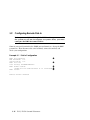
Configuring a PCI NVRAM Module.................................................... 2-20
Testing the System ............................................................................. 2-21
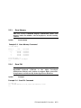
Set Commands .................................................................................... 2-24
Set Password................................................................................. 2-24
Set Secure ..................................................................................... 2-25
Secure Mode........................................................................................ 2-26
Login Command and Secure Mode ............................................... 2-26
Clear Password ............................................................................. 2-27
Resetting the Password ................................................................ 2-28
Stopping and Starting CPU ................................................................ 2-29
Updating Firmware ............................................................................ 2-29
Forcing a System Crash Dump ........................................................... 2-31
Using Environment Variables ............................................................ 2-32
set envar........................................................................................ 2-32
show envar .................................................................................... 2-33
Depositing and Examining Data......................................................... 2-34
Reading a File ..................................................................................... 2-37
Initializing the System........................................................................ 2-38
Finding Help ....................................................................................... 2-39
Environment Variable Summary........................................................ 2-40
auto_action.................................................................................... 2-42
bootdef_dev ................................................................................... 2-42
boot_osflags................................................................................... 2-43
com1_baud .................................................................................... 2-45
com1_mode.................................................................................... 2-45
console........................................................................................... 2-46
2.18.7
ew*0_mode.................................................................................... 2-47
2.18.8
ew*0_protocols .............................................................................. 2-47
2.18.9
kbd_hardware_type ...................................................................... 2-48
2.18.10
language........................................................................................ 2-48
2.18.11
os_type .......................................................................................... 2-49
2.18.12
password ....................................................................................... 2-49
2.18.13
pci_parity ...................................................................................... 2-50
2.18.14
pk*0_fast....................................................................................... 2-50
2.18.15
pk*0_host_id ................................................................................. 2-51
2.18.16
pk*0_soft_term ............................................................................. 2-51
2.18.17
tt_allow_login................................................................................ 2-52
2.19
Switching from SRM to AlphaBIOS Console ...................................... 2-53
2.20
Running the AlphaBIOS Console ....................................................... 2-54
2.20.1
Running Configuration Utilities................................................... 2-57
Chapter 3
3.1
3.2
3.3
3.3.1
3.3.2
3.4
3.5
3.6
3.7
3.8
3.9
3.10
3.11
3.12
3.13
3.14
3.14.1
3.14.2
3.14.3
3.14.4
3.14.5
3.14.6
3.14.7
3.14.8
3.14.9
Remote Management Console
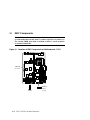
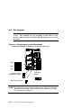
RMC Components ................................................................................. 3-2
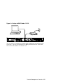
Terminal Setup ..................................................................................... 3-4
Operating Modes................................................................................... 3-6
Snoop Mode (Default Mode)............................................................ 3-7
Bypass Modes ................................................................................. 3-7
Entering the RMC................................................................................. 3-8
SRM Environment Variables for COM1 ............................................... 3-9
Status Monitoring ............................................................................... 3-10
Remote Power (On/Off) ....................................................................... 3-12
Remote Halt (In/Out) .......................................................................... 3-14
Configuring Remote Dial-In................................................................ 3-16
Configuring Dial-Out Alert ................................................................. 3-18
Dialing In ............................................................................................ 3-21
Resetting the RMC to Factory Defaults.............................................. 3-22
Troubleshooting Tips .......................................................................... 3-24
RMC Commands ................................................................................. 3-26
clear alert...................................................................................... 3-28
clear port....................................................................................... 3-28
disable alert .................................................................................. 3-29
disable remote............................................................................... 3-29
enable alert ................................................................................... 3-30
enable remote................................................................................ 3-31
halt (in/out) ................................................................................... 3-32
hangup .......................................................................................... 3-33
help or ?......................................................................................... 3-33
v
3.14.10
3.14.11
3.14.12
3.14.13
3.14.14
3.14.15
3.14.16
3.14.17
3.14.18
3.14.19
3.14.20
3.14.21
3.14.22
3.14.23
3.14.24
power off ....................................................................................... 3-34
power on........................................................................................ 3-34
quit................................................................................................ 3-35
reset .............................................................................................. 3-36
send alert ...................................................................................... 3-36
set alert ......................................................................................... 3-37
set com1_mode .............................................................................. 3-38
set dial........................................................................................... 3-39
set escape ...................................................................................... 3-40
set init ........................................................................................... 3-41
set logout....................................................................................... 3-42
set password ................................................................................. 3-42
set user.......................................................................................... 3-42
set wdt........................................................................................... 3-43
status ............................................................................................ 3-43
Appendix A
A.1
A.2
A.3
A.4
A.5
A.6
Warnings and Cautions ........................................................................A-2
Remove Power from the System ...........................................................A-3
Open the System ...................................................................................A-5
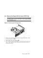
Remove the Floppy Disk Enclosure (DS10 Only) .................................A-9
Set Jumpers ........................................................................................A-10
Restore Power .....................................................................................A-12
Appendix B
B.1
B.1.1
B.1.2
Setting Jumpers
Regulatory Compliance Notices
Class A and Class B Ratings.................................................................B-1
Class A Device Notices....................................................................B-2
Class B Device Notices....................................................................B-5
Index
Examples
1–1
1–2
1–3
1–4
1–5
1–6
vi
Power-Up Display – DS10..................................................................... 1-5
Power-Up Display - DS10L Serial and Graphics Consoles .................. 1-7
Booting Tru64 UNIX from a Local Disk ............................................... 1-9
Booting Tru64 UNIX from a Remote Disk.......................................... 1-11
Installing Tru64 UNIX ....................................................................... 1-13
Booting OpenVMS from a Local Disk ................................................. 1-15
1–7
1–8
1–9
1–10
1–11
1–12
1–13
2–1
2–2
2–3
2–4
2–5
2–6
2–7
2–8
2–9
2–10
2–11
2–12
2–13
2–14
2–15
2–16
2–17
2–18
2–19
2–20
2–21
2–22
2–23
2–24
2–25
3–1
3–2
Booting OpenVMS from a Disk on a Cluster ...................................... 1-17
Booting OpenVMS from a Remote Disk.............................................. 1-19
Installing OpenVMS ........................................................................... 1-21
Starting LFU from the SRM Console.................................................. 1-24
Booting LFU from the CD-ROM ......................................................... 1-26
Updating Firmware from the Floppy Disk ......................................... 1-28
Updating Firmware from a Network Device ...................................... 1-30
Show Config Command......................................................................... 2-8
Show Device Command....................................................................... 2-10
Show Memory Command .................................................................... 2-13
Show PAL Command .......................................................................... 2-13
Show Power Command ....................................................................... 2-14
Show Version Command ..................................................................... 2-15
Editing the nvram Script .................................................................... 2-17
Clearing the nvram Script .................................................................. 2-17
Boot Command.................................................................................... 2-19
Prcache Command .............................................................................. 2-20
Test Command .................................................................................... 2-21
Set Password Command ..................................................................... 2-24
Set Secure Command .......................................................................... 2-25
Secure Mode and Login Command ..................................................... 2-27
Clear Password Command.................................................................. 2-27
Lfu Command ..................................................................................... 2-29
Crash Command ................................................................................. 2-31
Setting and Showing Environment Variables .................................... 2-33
Creating a User-Defined Environment Variable ................................ 2-33
Deposit Command............................................................................... 2-35
Examine Command............................................................................. 2-36
More Command................................................................................... 2-37
Initialize Command ............................................................................ 2-38
Help Command ................................................................................... 2-39
Changing Baud Rate........................................................................... 2-45
Dial-In Configuration.......................................................................... 3-16
Dial-Out Alert Configuration.............................................................. 3-18
Figures
1–1
1–2
1–3
1–4
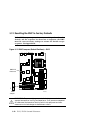
Check Power Setting – DS10 ................................................................ 1-2
Location of DS10 Control Panel and On/Off Button ............................. 1-3
Location of DS10L Control Panel and On/Off Button........................... 1-4
Physical Numbering for DS10 PCI Slots .............................................. 1-6
vii
1–5
1–6
2–1
2–2
2–3
2–4
2–5
3–1
3–2
3–3
3–4
3–5
3–6
3–7
3–8
3–9
3–10
3–11
A–1
A–2
A–3
A–4
A–5
A–6
Halt/Reset Button – DS10................................................................... 1-36
Halt/Reset Button - DS10L ................................................................. 1-37
AlphaBIOS Boot Screen ...................................................................... 2-54
AlphaBIOS No Selections Found Screen ............................................ 2-55
AlphaBIOS Setup Screen.................................................................... 2-56
AlphaBIOS Setup Screen.................................................................... 2-57
Run Maintenance Program Dialogue Box .......................................... 2-58
Location of RMC Components on Motherboard – DS10 ....................... 3-2
Location of RMC Components on Motherboard - DS10L...................... 3-3
Setups for RMC Mode – DS10............................................................... 3-4
Setups for RMC Mode - DS10L ............................................................. 3-5
Bypass Mode ......................................................................................... 3-6
Power Button – DS10.......................................................................... 3-12
Power Button - DS10L ........................................................................ 3-13
Halt/Reset Button - DS10 ................................................................... 3-14
Halt/Reset Button - DS10L ................................................................. 3-15
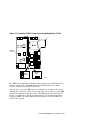
RMC Jumpers (Default Positions) – DS10.......................................... 3-22
RMC Jumpers (Default Positions) – DS10L ....................................... 3-23
Removing Power - DS10 System...........................................................A-3
Removing Power - DS10L System.........................................................A-4
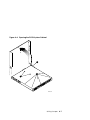
Opening the DS10 System Cabinet.......................................................A-5
Opening the DS10L System Cabinet ....................................................A-7
Removing the DS10 Floppy Disk ..........................................................A-9
Setting Jumpers on the Motherboard .................................................A-10
Tables
1–1
1–2
1–3
1–4
2–1
2–2
2–3
2–4
2–5
2–6
2–7
2–8
3–1
3–2
3–3
viii
Control Panel Functions – DS10........................................................... 1-3
Control Panel Functions - DS10L ......................................................... 1-4
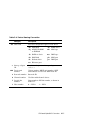
File Locations for Creating Update Diskettes on a PC....................... 1-27
LFU Command Summary................................................................... 1-33
Summary of SRM Console Commands ................................................. 2-3
Syntax for SRM Console Commands .................................................... 2-5
Special Characters for SRM Console .................................................... 2-6
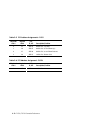
Device Naming Convention................................................................. 2-11
PCI Address Assignments – DS10 ...................................................... 2-12
PCI Address Assignment - DS10L ...................................................... 2-12
Environment Variable Summary........................................................ 2-40
Settings for boot_osflags Bootflags (OpenVMS).................................. 2-44
SRM Environment Variables for COM1 ............................................... 3-9
Status Command Fields...................................................................... 3-10
Elements of Dial String and Alert String ........................................... 3-20
3–4
A–1
A–2
RMC Troubleshooting ......................................................................... 3-24
Factory Default Switch Settings.........................................................A-11
Jumpers and Factory Default Positions..............................................A-11
ix
Preface
Intended Audience
This manual is for service providers, managers and operators of Compaq
AlphaServer DS10, AlphaServer DS10L, and AlphaStation DS10 systems.
Document Structure
This manual uses a structured documentation design. Topics are organized into
small sections, usually consisting of two facing pages. Most topics begin with an
abstract that provides an overview of the section, followed by an illustration or
example. The facing page contains descriptions, procedures, and syntax
definitions.
This manual has three chapters, two appendices, and an index:
•
Chapter 1, Operations, provides basic operating instructions, including
powering up the system, booting, and operating system installation.
•
Chapter 2, SRM and AlphaBIOS Consoles, presents the command-line
interface that supports the Tru64 UNIX and OpenVMS operating systems
and the graphical interface that supports some utility programs. The SRM
console is used to bootstrap the operating system, configure and test the
system hardware, examine system options for errors, and set or change
environment variables. AlphaBIOS is used to run utilities.
•
Chapter 3, Remote Management Console, describes how to manage the
system from a remote location.
•
Appendix A, Setting System Jumpers, describes how to check and reset
if necessary the Halt/Reset select jumper and remote management console
jumper.
•
Appendix B, Regulatory Compliance Notices, contains regulatory
compliance notices for this computer system.
xi
Conventions
In examples of SRM console output, commands the user enters are presented in
boldface type, while the system’s output is in regular type. Comments on the
examples are either called out with circled numbers (➊➋➌) or are preceded by a
pound sign (#) and are given in boldface italics.
Revision levels, dates and devices listed in examples are for example only; your
results may vary according to the configuration of your system.
NOTE: In many ways DS10 and DS10L systems are identical. This manual
uses DS10 systems for most illustrations and examples; DS10 screen
examples may have more devices shown than equivalent DS10L
screens, and other minor differences may appear. Where significant
differences exist, an illustration or example of a DS10L is presented
separately.
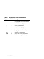
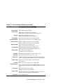
Documentation Titles
This following DS10/DS10L documentation is available.
Title
Order No.
DS10 / DS10L Console Reference
EK-DS10S-CR
Safety Booklet
296382-021
DS10 Quick Setup Poster
EK-DS10S-CP
DS10 User Reference Card
EK-DS10S-UR
DS10 Rackmount Guide
EK-DS10S-RM
DS10 User Information CD
AG-RHD8B-BE
DS10L Quick Setup Poster
EK-DS10L-CP
DS10L User Reference Card
EK-DS10L-UR
DS10L User Information CD
AG-RLD4A-BE
Information on the Internet
Visit the Compaq Web site at www.compaq.com for service tools and more
information about the AlphaServer DS10 / DS10L, AlphaStation DS10 systems.
xii
Chapter 1
Operations
This chapter provides basic operating instructions, including powering up the
system, booting, and operating system installation. Note that your choice of
operating system has already been installed at the factory; this information is
provided so that should you decide to change operating systems, you may. It
also provides information about updating firmware.
Sections in this chapter are:
•
Powering Up the System
•
Power-Up Display
•
Booting Tru64 UNIX
•
Installing Tru64 UNIX
•
Booting OpenVMS
•
Installing OpenVMS
•
Switching Between Operating Systems
•
Updating Firmware
•
Using the Halt Button
•
Halt Assertion
NOTE: In many ways the DS10 and DS10L systems are identical. This
manual uses DS10 systems for most illustrations and examples. Where
significant differences exist, an illustration or example of a DS10L is
presented separately.
Operations 1-1
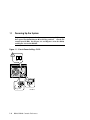
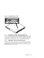
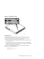
1.1
Powering Up the System
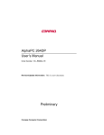
To power up the system, check your power setting (DS10 only),
then press the On/Off button ❶ to the On position.
Check the
control panel LEDs. See Figure 1–1 and Figure 1–2 for the DS10,
and Figure 1–3 for the DS10L.
Figure 1–1 Check Power Setting – DS10
115V
230V
PK1047a
1-2
DS10 / DS10L Console Reference
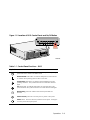
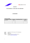
Figure 1–2 Location of DS10 Control Panel and On/Off Button
PK1043b
Table 1–1 Control Panel Functions – DS10
Symbol
Function
Halt button. Under OpenVMS and Tru64 UNIX, suspends the operating
system and returns control to the SRM console.
Environmental amber LED. On indicates Temperature or Fan LEDs are
on. Flashes when operating system invokes it as an alert.
Temperature amber LED. On indicates internal temperature exceeds
operating conditions. The system shuts down 30 seconds after this LED
lights.
Fan amber LED. On indicates that at least one of the three fans in the
system has failed. The system shuts down 30 seconds after this LED lights.
Disk Activity green LED. Flashes when internal system disks are
accessed.
Power Present green LED. On when power is present in the system.
Power button. Push in to start the system and connect power. Push again
to remove power and stop the system.
Operations 1-3
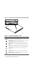
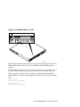
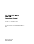
Figure 1–3 Location of DS10L Control Panel and On/Off Button
1
PK2216
Table 1–2 Control Panel Functions - DS10L
Symbol
Function
Halt button. Under OpenVMS and Tru64 UNIX, suspends the operating
system and returns control to the SRM console.
Environmental amber LED. On indicates Temperature or Fan LEDs are
on. Flashes when operating system invokes it as an alert.
Temperature amber LED. On indicates internal temperature exceeds
operating conditions. The system shuts down 30 seconds after this LED
lights.
Fan amber LED. On indicates that at least one of the three fans in the
system has failed. The system shuts down 30 seconds after this LED lights.
Disk Activity green LED. Flashes when internal system disks are
accessed.
Power Present green LED. On when power is present in the system.
Power button ❶. Push in to start the system and connect power. Push
again to remove power and stop the system.
1-4
DS10 / DS10L Console Reference
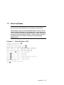
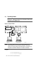
1.2
Power-Up Display
DS10 systems have four physical PCI slots; the DS10L system
has one, hence the different power-up displays shown below.
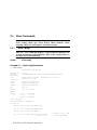
Testing begins after pressing the On/Off button, and screen text
similar to that in Example 1–1 displays (if the console terminal is
a serial terminal connected to the COM1 port), along with status
messages in the control panel display. If the console terminal is
a graphics monitor, only the last few lines of the power-up
display print.
Example 1–1 Power-Up Display – DS10
256 Meg of system memory ➊
probing hose 0, PCI
probing PCI-to-ISA bridge, bus 1 ➋
probing PCI-to-PCI bridge, bus 2 ➋
bus 0, slot 9 -- ewa -- DE500-BA Network Controller
bus 0, slot 11 -- ewb -- DE500-BA Network Controller
bus 0, slot 13 -- dqa -- Acer Labs M1543C IDE
bus 0, slot 13 -- dqb -- Acer Labs M1543C IDE
bus 0, slot 14 ➌-- vga -- DEC PowerStorm
bus 2,➍slot 0 -- pka -- NCR 53C875
bus 2,➍slot 1 -- pkb -- NCR 53C875
bus 2,➍slot 2 -- ewc -- DE500-AA Network Controller
bus 0,➎ slot 16 -- pkc -- QLogic ISP1020
bus 0,➏ slot 17 -- dra -- Mylex DAC960
Testing the System
Testing the Disks (read only)
>>> ➐
Operations 1-5
Figure 1–4 Physical Numbering for DS10 PCI Slots
PCI Slot 4
64 Bit
PCI Slot 3
64 Bit
PCI Slot 2
64 Bit
PCI Slot 1
32 Bit
PK1045-99
➊
➋
Memory size is determined.
➌
Power-up slot 14 corresponds to the bottom physical slot, slot 1.
The PCI bridges and attendant buses (indicated as IODn by the console)
are probed and the devices are reported. I/O adapters are configured.
Slot Location
Physical Slot Number
Logical Slot Number
Top
4
17
Second from top
3
16
Second from bottom
2
15
Bottom
1
14
➍
These devices are behind bridge of the card in logical slot 15, physical slot
2, second from the bottom.
➎
This device in is logical slot 16, physical slot 3.
➏
➐
Logical slot 17 is physical slot 4, the top slot.
The SRM console banner and prompt (>>>) are printed.
The SRM console is a command-line interface you use to set or read system
parameters.
If the auto_action environment variable is set to boot or restart and the
os_type environment variable is set to unix or openvms, the Tru64 UNIX
or OpenVMS operating system boots. See Section 2.18 for information on
environment variables.
1-6
DS10 / DS10L Console Reference
Example 1–2 Power-Up Display - DS10L Serial and Graphics
Consoles
Note: There is only one PCI slot on the DS10L; its logical slot number is 17.
Serial Console
256 Meg of system memory ➊
probing hose 0, PCI
probing PCI-to-ISA bridge, bus 1 ➋
bus 0, slot 9 -- ewa -- DE500-BA Network
bus 0, slot 11 -- ewb -- DE500-BA Network
bus 0, slot 13 -- dqa -- Acer Labs M1543C
bus 0, slot 13 -- dqb -- Acer Labs M1543C
bus 0,➌ slot 17 -- dra -- Mylex DAC960
Testing the System
Testing the disks (read only)
Controller
Controller
IDE
IDE
Testing the Network
System Temperature is 36 degrees C
Initializing GCT/FRU at 1f6000
COMPAQ AlphaServer DS10L 466 MHz Console V5.7-0 Jan 14 2000 09:59:58
>>> ➍
➊
Memory size is determined.
➋
The PCI bridges and attendant buses (indicated as IODn by the console)
are probed and the devices are reported. I/O adapters are configured.
➌
➍
The power-up logical slot is always 17 on the DS10L.
The SRM console banner and prompt (>>>) are printed.
The SRM console is a command-line interface you use to set or read system
parameters.
If the auto_action environment variable is set to boot or restart and the
os_type environment variable is set to unix or openvms, the Tru64 UNIX
or OpenVMS operating system boots.
See Section 2.18 for information on environment variables. See Chapter 2
for SRM console and AlphaBIOS information.
Operations 1-7
Graphics Console
Os_type
UNIX-console CIPCA drive not started
Testing the System
Testing the disks (read only)
Testing the Network
System Temperature is 36 degrees C
Initializing GCT/FRU at 1f6000
COMPAQ AlphaServer DS10L 466 MHz Console V5.7-0 Jan 13 2000 09:59:58
1-8
DS10 / DS10L Console Reference
1.3
Booting Tru64 UNIX
Tru64 UNIX® can be booted from a local disk or a remote disk
through an Ethernet connection. Refer to the documentation
shipped with the operating system for booting instructions.
1.3.1
Booting from a Local Disk
Example 1–3 Booting Tru64 UNIX from a Local Disk
>>> sho device
➊
dka100.1.0.2000.0
dka300.3.0.2000.0
dka500.5.0.2000.0
dkb0.0.0.2001.0
dkb200.2.0.2001.0
dkb400.4.0.2001.0
dkc0.0.0.16.0
dkc200.2.0.16.0
dqa1.1.0.13.0
dra1.0.0.17.0
dra2.0.0.17.0
dva0.0.0.0.0
ewa0.0.0.9.0
ewb0.0.0.11.0
ewc0.0.0.2002.0
pka0.7.0.2000.0
DKA100
DKA300
DKA500
DKB0
DKB200
DKB400
DKC0
DKC200
DQA1
DRA1
DRA2
DVA0
EWA0
EWB0
EWC0
PKA0
RZ1CB-CA
RZ1CB-CA
RZ1EF-AB
RZ1CB-CA
RZ1DB-CS
RZ1CB-CA
RZ1CB-BA
RZ1CB-BA
CD-532E
1 Member JBOD
1 Member JBOD
LYJ0
LYJ0
0370
LYJ0
0307
LYJ0
LYG0
LYG0
1.0A
➋
08-00-2B-86-1B-BA
08-00-2B-86-1B-BB
00-06-2B-00-26-1C
SCSI Bus ID 7
>>> boot -file vmunix -flags a dkc0
(boot dkc0.0.0.9.0 -file vmunix -flags a)
block 0 of dkc0.0.0.9.0 is a valid boot block
reading 16 blocks from dkc0.0.0.9.0
bootstrap code read in
base = 1ee000, image_start = 0, image_bytes = 2000
initializing HWRPB at 2000
initializing page table at 1fff0000
initializing machine state
setting affinity to the primary CPU
jumping to bootstrap code
➌
Tru64 UNIX boot - Fri Aug 7 20:30:19 EDT 1999
Loading vmunix ...
. . .
The system is ready.
Tru64 UNIX Version V4.0E (sabl28.eng.pko.dec.com) console
login:
************************************************************************
* Starting Desktop Login on display :0...
* Wait for the Desktop Login screen before logging in.
************************************************************************
➍
Operations 1-9
➊
The show device command displays device information, including
name and type of connection to the system. See Section 2.3.2 for a
description of the show device command and the device naming
convention.
➋
The operating system is on the third disk connected to the system
through the controller in slot 3 of the PCI. The name of this device,
dkc0, is used as an argument to the boot command.
➌
This command loads Tru64 UNIX from the disk dkc0, using the boot
file vmunix and autobooting to multiuser mode. See Section 2.5 for a
description of the boot command.
The boot command accepts the name of a boot device, a boot file
name through the -file option, and boot flags through the -flags
option. The environment variables bootdef_dev, boot_file, and
boot_osflags can also be used to specify the default boot device or
device list, the default boot file, and flag information. When an option
and the corresponding environment variable are both in a command
string, the option overrides the environment variable. The value of
the environment variable, however, is not changed. See Section 2.18
for information about environment variables.
➍
The operating system banner displays.
1-10 DS10 / DS10L Console Reference
1.3.2
Booting from a Remote Disk
Example 1–4 Booting Tru64 UNIX from a Remote Disk
>>> show device
. . .
ewa0.0.0.8.0
➊
EWA0
08-00-2B-E2-9C-60
>>>
>>> boot -flags an -protocols bootp ewa
(boot ewa0.0.0.4.1 -flags an)
Building FRU table
➋
➌
Trying BOOTP boot.
Broadcasting BOOTP Request...
Received BOOTP Packet File Name: /var/adm/ris/ris0.alpha/hvmunix
local inet address: 16.122.128.26
remote inet address: 16.122.128.59
TFTP Read File Name: /var/adm/ris/ris0.alpha/hvmunix
..........................................................................................
bootstrap code read in
base = 200000, image_start = 0, image_bytes = 9a0fa0
initializing HWRPB at 2000
initializing page table at 1f2000
initializing machine state
setting affinity to the primary CPU
jumping to bootstrap code
Secondary boot program - Thu Aug 1 22:33:13 EST 1999
Loading vmunix ...
.
.
.
The system is ready.
Tru64 UNIX Version V4.0E (sabl28.eng.pko.dec.com) console
➍
Operations 1-11
➊
The show device command displays device information, including
name and type of connection to the system. See Section 2.3.2 for a
description of the show device command and the device naming
convention.
➋
The operating system is on a remote disk accessed through the
Ethernet controller in slot 4 of the PCI. The name of this device,
ewa0, is used as an argument to the boot command.
➌
This command loads Tru64 UNIX from ewa0, autobooting to
multiuser mode. See Section 2.5 for a description of the boot
command.
The boot command accepts the name of a boot device, a boot file
name through the -file option, and boot flags through the -flags
option. The environment variables bootdef_dev, boot_file, and
boot_osflags can also be used to specify the default boot device or
device list, the default boot file, and flag information. When an option
and the corresponding environment variable are both in a command
string, the option overrides the environment variable. The value of
the environment variable, however, is not changed. See Section 2.18
for information about environment variables.
➍
The operating system banner displays.
1-12 DS10 / DS10L Console Reference
1.4
Installing Tru64 UNIX
Tru64 UNIX is installed from the CD-ROM. Refer to the
documentation shipped with the CD-ROM for installation
instructions.
Example 1–5 Installing Tru64 UNIX
>>> show device
. . .
dka500.5.0.7.1
DKA500
RRD47
1337
➊
. . .
>>>
➊
>>> boot dka500
(boot dka500.5.0.7.1 -flags A)
block 0 of dka500.5.0.7.1 is a valid boot block
reading 16 blocks from dka500.5.0.7.1
bootstrap code read in
base = 1ee000, image_start = 0, image_bytes = 2000
initializing HWRPB at 2000
initializing page table at 1fff0000
initializing machine state
setting affinity to the primary CPU
jumping to bootstrap code
Tru64 UNIX boot - Thu Jul 16 16:59:31 EDT 1999
Loading vmunix ...
.
.
.
INIT: SINGLE-USER MODE
Initializing system for Tru64 UNIX installation.
Please wait...
*** Performing CDROM Installation
Loading installation process and scanning system hardware.
[The “Welcome to the Tru64 UNIX Installation Procedure” appears.]
➋
Operations 1-13
➊
Use the boot command to install the operating system from the CDROM, which is either dka500 or dqa0.
➋
See your operating system documentation for further installation
instructions.
1-14 DS10 / DS10L Console Reference
1.5
Booting OpenVMS
OpenVMS can be booted from a local disk, a disk connected
through a cluster, or a remote disk through an Ethernet
connection. Refer to the documentation shipped with the
operating system for booting instructions.
1.5.1
Booting OpenVMS from a Local Disk
Example 1–6 Booting OpenVMS from a Local Disk
➊
>>> show device
. . .
dka200.2.0.7.1
DKA200
RZ1CB-CA
LYJ0
. . .
>>>
➋
>>> show boot_reset
boot_reset
ON
>>> show bootdef_dev
bootdef_dev
dka200.2.0.7.1
➌
>>> boot
(boot dka200.2.0.7.1 -flags 0,0)
block 0 of dka200.2.0.7.1 is a valid boot block
reading 893 blocks from dka200.2.0.7.1
bootstrap code read in
base = 1fa000, image_start = 0, image_bytes = 6fa00
initializing HWRPB at 2000
initializing page table at 1fff0000
initializing machine state
setting affinity to the primary CPU
jumping to bootstrap code
➍
OpenVMS (TM) Alpha Operating System, Version 7.1-2
$!Copyright(c) 1999 Digital Equipment Corporation. All rights reserved.
%STDRV-I-STARTUP, OpenVMS startup begun at 30-JUL-1999 11:47:11.04
%MSCPLOAD-I-CONFIGSCAN, enabled automatic disk serving
Continued on next page
Operations 1-15
Example 1–6 Booting OpenVMS from a Local Disk (Continued)
. . .
The OpenVMS system is now executing the site-specific startup commands.
. . .
Welcome to OpenVMS (TM) Alpha Operating System, Version V7.1-2
➎
Username:
➊
The show device command displays device information. See Section
2.3.2 for a description of the show device command and the device
naming convention.
➋
The boot_reset environment variable was previously set to “on,”
causing the power-up trace to display when the system initializes (see
Section 1.2). See Section 2.18 for commands used with environment
variables.
➌
The bootdef_dev environment variable specifies the default boot
device. In this example, the default boot device was previously set to
dka200.2.0.7.1.
➍
No boot device is specified in the boot command; the default boot
device was set with the environment variable. See Section 2.5 for a
description of the boot command.
The boot command accepts the name of a boot device, a boot file
name through the -file option, and boot flags through the -flags
option. The environment variables bootdef_dev, boot_file, and
boot_osflags can also be used to specify the default boot device or
device list, the default boot file, and flag information. When an option
and the corresponding environment variable are both in a command
string, the option overrides the environment variable. The value of
the environment variable, however, is not changed. See Section 2.18
for information about environment variables.
➎
The operating system banner displays.
1-16 DS10 / DS10L Console Reference
1.5.2
Booting OpenVMS from a Disk on a Cluster
Example 1–7 Booting OpenVMS from a Disk on a Cluster
➊
>>> show bootdef_dev
bootdef_dev
dua110.0.0.8.0
➋
>>> show device
.
. .
dua110.0.0.8.0
$1$DIA110 (DENVER)
RF74
➌
. . .
>>> boot
dua110.0.0.8.0 -flags 0)
Building FRU table
.
.
.
➍
(boot
Welcome to OpenVMS Alpha (TM) Operating System, Version V7.1-2
➎
Operations 1-17
➊
The bootdef_dev environment variable specifies the default boot
device.
➋
The show device command displays device information, including
name and type of connection to the system. See Section 2.3.2 for a
description of the show device command and the device naming
convention.
➌
➍
The disk dua110.0.0.8.0 is on the cluster that includes this system.
No boot device is specified in the boot command; the default boot
device was set with the environment variable. See Section 2.5 for a
description of the boot command.
The boot command accepts the name of a boot device, a boot file
name through the -file option, and boot flags through the -flags
option. The environment variables bootdef_dev, boot_file, and
boot_osflags can also be used to specify the default boot device or
device list, the default boot file, and flag information. When an option
and the corresponding environment variable are both in a command
string, the option overrides the environment variable. The value of
the environment variable, however, is not changed. See Section 2.18
for information about environment variables.
➎
The operating system banner prints.
1-18 DS10 / DS10L Console Reference
1.5.3
Booting OpenVMS from a Remote Disk
Example 1–8 Booting OpenVMS from a Remote Disk
>>>
show device
. . .
ewa0.0.0.8.0
EWA0
08-00-2B-E2-9C-60
. . .
>>>
>>> boot ewa0 -flags 0
(boot ewa0.0.0.2.0 -flags 0)
Building FRU table
➊
➊
➋
Trying MOP boot..............
Network load complete.
. . .
Welcome to OpenVMS Alpha (TM) Operating System, Version V7.1-2
➌
Operations 1-19
➊
The show device command displays device information, including
name and type of connection to the system. In this example the
Ethernet connection is ewa0. See Section 2.3.2 for a description of the
show device command and the device naming convention.
➋
The boot command specifies ewa0 as the boot device. See Section 2.5
for a description of the boot command.
The boot command accepts the name of a boot device, a boot file
name through the -file option, and boot flags through the -flags
option. The environment variables bootdef_dev, boot_file, and
boot_osflags can also be used to specify the default boot device or
device list, the default boot file, and flag information. When an option
and the corresponding environment variable are both in a command
string, the option overrides the environment variable. The value of
the environment variable, however, is not changed. See Section 2.18
for information about environment variables.
➌
The operating system banner prints.
1-20 DS10 / DS10L Console Reference
1.6
Installing OpenVMS
OpenVMS is installed from the CD-ROM. Refer to the
documentation shipped with the OpenVMS kit for complete
installation instructions.
Example 1–9 Installing OpenVMS
>>> boot -flags 0,0 dka500
Initializing...
SROM V3.0 on cpu0
.
. [The initialization display prints. See Section 1.2.]
.
AlphaServer DS10 Console V5.7-0 Jan 13 2000 15:17:48
➊
CPU 0 booting
(boot dka500.5.0.1.1 -flags 0,0)
Building FRU table
block 0 of dka500.5.0.1.1 is a valid boot block
reading 1002 blocks from dka500.5.0.1.1
bootstrap code read in
base = 200000, image_start = 0, image_bytes = 7d400
initializing HWRPB at 2000
initializing page table at 1f2000
initializing machine state
setting affinity to the primary CPU
jumping to bootstrap code
OpenVMS (TM) Alpha Operating System, Version 7.1x
➋
%SMP-I-SECMSG, CPU #01 message: P01>>>START
%SMP-I-CPUBOOTED, CPU #01 has joined the PRIMARY CPU in multiprocessor operation
Installing required known files...
Configuring devices...
****************************************************************
You can install or upgrade the OpenVMS Alpha operating system
or you can install or upgrade layered products that are included
on the OpenVMS Alpha operating system CD-ROM.
You can also execute DCL commands and procedures to perform
"standalone" tasks, such as backing up the system disk.
Continued on next page
Operations 1-21
Example 1–9 Installing OpenVMS (Continued)
Please choose one of the following:
1)
2)
3)
4)
5)
Install or upgrade OpenVMS Alpha Version 7.1x
List layered product kits that this procedure can install
Install or upgrade layered product(s)
Execute DCL commands and procedures
Shut down this system
Enter CHOICE or ? to repeat menu: (1/2/3/4/5/?)
➊
Use the boot command to install the operating system from the CDROM, which is either dka500 or dqa0.
➋
See your operating system documentation for installation
instructions.
1-22 DS10 / DS10L Console Reference
1.7
Switching Between Operating Systems
The system supports multiple operating systems on different
system and data disks not in the machine at the same time. That
is, you can have a set of disks for each operating system.
CAUTION: This operation is not for the faint hearted especially if you have a
shadow system disk and shadow arrays. The file structures of the
operating systems are incompatible and therefore all disks must be
removed from the system and upon reinstallation must be replaced
in exactly the same physical locations. It is therefore necessary to
keep track of the location of each disk in the system.
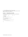
1.7.1
Switching to Tru64 UNIX or OpenVMS
Use the following procedure:
1. Shut down the operating system and power off the system.
2. Remove and mark the physical location of each disk in the system.
3. Either place blank disks or your Tru64 UNIX or OpenVMS disk set into the
system. No matter which disk set you are placing into the system, be
sure that each disk is placed in the same physical location from
which it was removed.
4. Power on the system.
5. Set the operating system at the console prompt (see Section 2.18.11).
6. Press the Halt/Reset button to reset the system.
7. Either install Tru64 UNIX (see Section 1.4) or OpenVMS (see Section 1.6) or
boot the operating system.
Operations 1-23
1.8
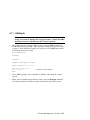
Updating Firmware
Start the Loadable Firmware Update (LFU) utility by issuing the
lfu command at the SRM console prompt, booting it from the
CD-ROM while in the SRM console.
Example 1–10 Starting LFU from the SRM Console
Revision levels and devices listed are for example only; your results may vary.
>>> lfu
Checking dqa0.0.0.13.0 for the option firmware files. . .
Checking dva0 for the option firmware files. . .
Option firmware files were not found on CD or floppy.
If you want to load the options firmware,
please enter the device on which the files are located(ewa0),
or just hit <return> to proceed with a standard console update: dva0
Please enter the name of the options firmware files list, or
Hit <return> to use the default filename (ds10fw.txt) :
Copying ds10fw.txt from dva0. . .
Copying PC264NT.ROM from dva0. . .
Copying DS10SRM.ROM from dva0. . .
1-24 DS10 / DS10L Console Reference
***** Loadable Firmware Update Utility *****
-----------------------------------------------------------------Function
Description
-----------------------------------------------------------------Display
Displays the system’s configuration table.
Exit
Done exit LFU (reset).
List
Lists the device, revision, firmware name, and update
revision.
Readme
Lists important release information.
Update
Replaces current firmware with loadable data image.
Verify
Compares loadable and hardware images.
? or Help
Scrolls this function table.
-----------------------------------------------------------------UPD> update *
Confirm update on:
nt
srm
[Y/(N)]y
WARNING: updates may take several minutes to complete for each
device.
DO NOT ABORT!
nt
Updating to 5.70...
srm
Updating to 5.7-0...
Verifying 5.70...
PASSED.
Verifying 5.7-0...
PASSED.
UPD> exit
NOTE: If the system has been shut down from a booted program (most
commonly, the operating system) or in some other way halted back to
the SRM console, the system must be reset before running LFU.
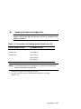
Use the Loadable Firmware Update (LFU) utility to update system firmware.
From the SRM console, start LFU by issuing the lfu command (see
Example 1–10). Also from the SRM console, LFU can be booted from the Alpha
CD-ROM (V5.4 or later), as shown in Example 1–11.
A typical update procedure is:
1.
Start LFU.
2.
Use the LFU list command to show the revisions of modules that LFU can
update and the revisions of update firmware.
3.
Use the LFU update command to write the new firmware.
Operations 1-25
4.
Use the LFU exit command to go back to the console.
The sections that follow show examples of updating firmware from the local CDROM, the local floppy, and a network device.
Example 1–11 Booting LFU from the CD-ROM
Revision levels and devices listed are for example only; your results may vary.
>>> show device
. . .
dka500.5.0.7.1
DKA500
RRD47 1645
. . .
>>> boot dka500
(boot dka500.5.0.7.1 -flags 0,0)
block 0 of dka500.5.0.7.1 is a valid boot block
..
jumping to bootstrap code
The default bootfile for this platform is
[DS10]DS10_LFU.EXE
Hit <RETURN> at the prompt to use the default bootfile.
Bootfile: <CR>
Starting Firmware Update Utility
***** Loadable Firmware Update Utility *****
...
UPD>
1-26 DS10 / DS10L Console Reference
1.8.1
Updating Firmware from Floppy Disks
Create two update diskettes before starting LFU: one for console
updates and one for I/O. See Section 1.8.2 for an example of the
update procedure.
Table 1–3 File Locations for Creating Update Diskettes on a PC
Console Update Diskette
I/O Update Diskette
ds10fw.txt
ds10fw.txt
pc264nt.rom
ccmab022.sys
ds10srm.rom
dfxaa310.sys
kzpsaa12.sys
cipca420.sys
NOTE: The filenames above are for example only, and may vary according to
where you obtained the update files.
1. Download the update files from the Internet.
2. On a PC, copy files onto two FAT-formatted diskettes as shown
in Table 1–3.
Operations 1-27
1.8.2
Performing the Update from Floppy Disks
Insert an update diskette (see Section 1.8.1) into the floppy
drive. Start LFU and select dva0 as the load device.
Example 1–12 Updating Firmware from the Floppy Disk
Revision levels and devices listed are for example only; your results may vary.
>>> lfu
Checking dqa0.0.0.13.0 for the option firmware files. . .
Checking dva0 for the option firmware files. . .
Option firmware files were not found on CD or floppy.
If you want to load the options firmware,
please enter the device on which the files are located(ewa0),
or just hit <return> to proceed with a standard console update: dva0
Please enter the name of the options firmware files list, or
Hit <return> to use the default filename (ds10fw.txt) :
Copying ds10fw.txt from dva0. . .
Copying PC264NT.ROM from dva0. . .
Copying DS10SRM.ROM from dva0. . .
1-28 DS10 / DS10L Console Reference
***** Loadable Firmware Update Utility *****
-----------------------------------------------------------------Function
Description
-----------------------------------------------------------------Display
Displays the system’s configuration table.
Exit
Done exit LFU (reset).
List
Lists the device, revision, firmware name, and update
revision.
Readme
Lists important release information.
Update
Replaces current firmware with loadable data image.
Verify
Compares loadable and hardware images.
? or Help
Scrolls this function table.
-----------------------------------------------------------------UPD> update *
Confirm update on:
nt
srm
[Y/(N)]y
WARNING: updates may take several minutes to complete for each
device.
DO NOT ABORT!
nt
Updating to 5.70...
srm
Updating to 5.7-0...
Verifying 5.70...
PASSED.
Verifying 5.7-0...
PASSED.
UPD> exit
NOTE: If the system has been shut down from a booted program (most
commonly, the operating system) or in some other way halted back to
the SRM console, the system must be reset before running LFU.
Operations 1-29
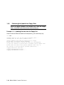
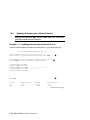
1.8.3
Updating Firmware from a Network Device
Copy files to the local MOP server’s MOP load area, start LFU,
and select ewa0 as the load device.
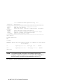
Example 1–13 Updating Firmware from a Network Device
Revision levels and devices listed are for example only; your results may vary.
***** Loadable Firmware Update Utility *****
Select firmware load device (cda0, dva0, ewa0), or
Press <return> to bypass loading and proceed to LFU: ewa0
➊
Please enter the name of the options firmware files list, or
Press <return> to use the default filename [DS10FW]:
Copying
Copying
Copying
Copying
Copying
DS10FW from EWA0 .
CCMAB022 from EWA0
DFXAA310 from EWA0
KZPSAA12 from EWA0
CIPCA420 from EWA0
.
...........................
............
.
.
.
.
UPD> list
Device
Nt
Srm
➋
➌
Current Revision
5.69
5.6-2
Filename
nt_fw
srm_fw
Update Revision
5.70
5.7-0
Continued on next page
1-30 DS10 / DS10L Console Reference
Before starting LFU, download the update files from the Internet. You will
need the files with the extension .SYS. Copy these files to your local MOP
server’s MOP load area.
➊
Select the device from which firmware will be loaded. The choices are
the CD-ROM, the internal floppy disk, or a network device. In this
example, a network device is selected.
➋
For the SRM console, AlphaBIOS console, and I/O adapter firmware,
select the file that has the firmware update, (ds10fw.txt ), or press
Enter.
In this example the default file, which has both console firmware
(AlphaBIOS and SRM) and I/O adapter firmware, is selected.
➌
Use the LFU list command to determine the revision of firmware in a
device and the most recent revision of that firmware available in the
selected file. In this example, the resident firmware for each console
(SRM and AlphaBIOS) and I/O adapter is at an earlier revision than
the firmware in the update file.
Continued on next page
Operations 1-31
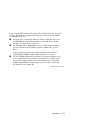
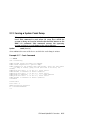
Example 1–13 Updating Firmware from a Network Device
(Continued)
UPD> update * -all
➍
WARNING: updates may take several minutes to complete for each device.
AlphaBIOS
DO NOT ABORT!
Updating to V6.40-1... Verifying V6.40-1... PASSED.
kzpsa0
DO NOT ABORT!
Updating to A11
... Verifying A11... PASSED.
kzpsa1
DO NOT ABORT!
Updating to A11
... Verifying A11... PASSED.
UPD> exit
➎
➍
The update command updates the device specified or all devices. In
this example, the wildcard indicates that all devices supported by the
selected update file will be updated. Typically LFU requests
confirmation before updating each console’s or device’s firmware. The
-all option eliminates the update confirmation requests.
➎
The exit command returns you to the console from which you entered
LFU (either SRM or AlphaBIOS).
1-32 DS10 / DS10L Console Reference
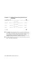
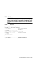
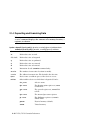
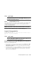
1.8.4
LFU Commands
The commands summarized in Table 1–4 are used to update
system firmware.
Table 1–4 LFU Command Summary
Command
display
exit
help
Function
Shows the physical configuration of the system.
Terminates the LFU program.
Displays the LFU command list.
lfu
Restarts the LFU program.
list
Displays the inventory of update firmware on the selected device.
readme
Lists release notes for the LFU program.
update
Writes new firmware to the module.
verify
Reads the firmware from the module into memory and compares
it with the update firmware.
display
The display command shows the physical configuration of the system. Display
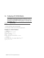
is equivalent to issuing the SRM console command show configuration.
Because it shows the slot for each module, display can help you identify the
location of a device.
exit
The exit command terminates the LFU program, causes system initialization
and testing, and returns the system to the console from which LFU was called.
Operations 1-33
help
The help (or ?) command displays the LFU command list, shown below.
--------------------------------------------------------------------Function
Description
--------------------------------------------------------------------Display
Displays the system’s configuration table.
Exit
Done exit LFU (reset).
List
Lists the device, revision, firmware name, and update
revision.
Lfu
Restarts LFU.
Readme
Lists important release information.
Update
Replaces current firmware with loadable data image.
Verify
Compares loadable and hardware images.
? or Help Scrolls this function table.
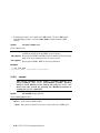
---------------------------------------------------------lfu
The lfu command restarts the LFU program. This command is used when the
update files are on a floppy disk. The files for updating both console firmware
and I/O firmware are too large to fit on a 1.44 MB disk, so only one type of
firmware can be updated at a time. Restarting LFU enables you to specify
another update file.
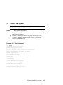
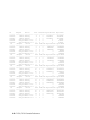
list
The list command displays the inventory of update firmware on the CD-ROM,
network, or floppy. Only the devices listed at your terminal are supported for
firmware updates.
The list command shows three pieces of information for each device:
•
Current Revision — The revision of the device’s current firmware
•
Filename — The name of the file used to update that firmware
•
Update Revision — The revision of the firmware update image
readme
The readme command lists release notes for the LFU program.
1-34 DS10 / DS10L Console Reference
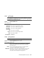
update
The update command writes new firmware to the module. Then LFU
automatically verifies the update by reading the new firmware image from the
module into memory and comparing it with the source image.
To update more than one device, you may use a wildcard but not a list. For
example, update k* updates all devices with names beginning with k, and
update * updates all devices. When you do not specify a device name, LFU tries
to update all devices; it lists the selected devices to update and prompts before
devices are updated. (The default is no.) The -all option eliminates the update
confirmation requests, enabling the update to proceed without operator
intervention.
CAUTION: Never abort an update operation.
Aborting corrupts the firmware on the module.
verify
The verify command reads the firmware from the module into memory and
compares it with the update firmware. If a module already verified successfully
when you updated it, but later failed tests, you can use verify to tell whether
the firmware has become corrupted.
Operations 1-35
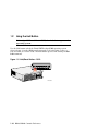
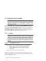
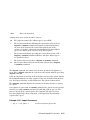
1.9
Using the Halt Button
Under OpenVMS and Tru64 UNIX, the halt button pauses the
operating system.
Use the Halt button to halt the Tru64 UNIX or OpenVMS operating system
when it hangs, clear the SRM console password (see Section 2.9.2), or force a
halt assertion (see Section 1.10). The Halt button operates like issuing an SRM
halt command.
Figure 1–5 Halt/Reset Button – DS10
PK1043b
1-36 DS10 / DS10L Console Reference
Figure 1–6 Halt/Reset Button - DS10L
1
PK2220
1.9.1
Using Halt to Shut Down the Operating System
You can use the Halt button if the Tru64 UNIX or OpenVMS operating system
hangs. Pressing the Halt button halts the operating system back to the SRM
console firmware. From the console, you can use the crash command to force a
crash dump at the operating system level. See Section 2.12 for an example.
1.9.2
Using Halt to Clear the Console Password
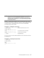
The SRM console firmware allows you to set a password to prevent unauthorized access to the console. If you forget the password, the Halt button, with the
login command, lets you clear the password and regain control of the console.
Section 2.9.2 describes the procedure.
Operations 1-37
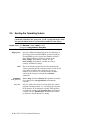
1.10 Halt Assertion
A halt assertion allows you to disable automatic boots of the
operating system so that you can perform tasks from the SRM
console.
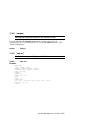
Under certain conditions, you might want to force a “halt assertion.” A halt
assertion differs from a simple halt in that the SRM console “remembers” the
halt. The next time you power up, the system ignores the SRM power-up script
(nvram) and ignores any environment variables that you have set to cause an
automatic boot of the operating system. The SRM console displays this
message:
Halt assertion detected
NVRAM power-up script not executed
AUTO_ACTION=BOOT/RESTART and OS_TYPE=NT ignored, if applicable
Halt assertion is useful for disabling automatic boots of the operating system
when you want to perform tasks from the SRM console. It is also useful for
disabling the SRM power-up script if you have accidentally inserted a command
in the script that will cause a system problem. These conditions are described
in the sections “Disabling Autoboot” and “Disabling the SRM Power-Up Script.”
You can force a halt assertion using the Halt button, the RMC halt command,
or the RMC haltin command. Observe the following guidelines for forcing a
halt assertion.
1.10.1
Halt Assertion with Halt Button or RMC Halt Command
Press the Halt button on the local system (or enter the RMC halt command
from a remote system) approximately five seconds after starting power up or
when the SRM console is running. The system halts at the SRM console, and
the halt status is saved. The next time the system powers up, the saved halt
status is checked.
NOTE: Wait 5 seconds after the system begins powering up before pressing the
Halt button or remotely entering the RMC halt command. Press the
button for several seconds.
1-38 DS10 / DS10L Console Reference
1.10.2
Halt Assertion with RMC Haltin Command
Enter the RMC haltin command at any time except during power-up. For
example, enter haltin during an operating system session or when the
AlphaBIOS console is running.
If you enter the RMC haltin command during a Tru64 UNIX or OpenVMS
session, the system halts back to the SRM console, and the halt status is saved.
The next time the system powers up, the saved halt status is checked.
If you enter the RMC haltin command when AlphaBIOS is running, the
interrupt is ignored. However, you can enter the RMC haltin command
followed by the RMC reset command to force a halt assertion. Upon reset, the
system powers up to the SRM console, but the SRM console does not load the
AlphaBIOS console.
The haltin command should always be followed by the haltout command.
1.10.3
Clearing a Halt Assertion
Clear a halt assertion as follows:
•
If the halt assertion was caused by pressing the Halt button or remotely
entering the RMC halt command, the console uses the halt assertion once,
then clears it.
•
If entering the RMC haltin command caused the halt assertion, enter the
RMC haltout command or cycle power on the local system.
1.10.4
Disabling Autoboot
The system automatically boots the selected operating system at power-up or
reset if the following environment variables are set:
•
For Tru64 UNIX and OpenVMS, the SRM environment variables os_type,
auto_action, bootdef_dev, boot_file, and boot_osflags
You might want to prevent the system from autobooting so you can perform
tasks from the SRM console. Use one of the methods described previously to
force a halt assertion. When the SRM console prompt is displayed, you can
enter commands to configure or test the system. Chapter 2 describes the SRM
console commands and environment variables.
Operations 1-39
1.10.5
Disabling the SRM Power-Up Script
The system has a power-up script (file) named “nvram” that runs every time the
system powers up. If you accidentally insert a command in the script that will
cause a system problem, disable the script by using one of the methods described
previously to force a halt assertion. When the SRM console prompt is displayed,
edit the script to delete the offending command. See Section 2.4 for more
information on editing the nvram script.
1-40 DS10 / DS10L Console Reference
Chapter 2
SRM and AlphaBIOS Consoles
The SRM console is the command-line interface that supports the Tru64 UNIX
and OpenVMS operating systems. The SRM console is used to bootstrap the
operating system, configure and test the system hardware, examine system
options for errors, and set or change environment variables. The AlphaBIOS
console is used to run certain utilities.
This chapter describes the SRM and AlphaBIOS console commands and
environment variables. Sections in this chapter are:
•
Invoking the SRM Console
•
Updating Firmware
•
Commands
•
Forcing a System Crash Dump
•
Show Commands
•
Using Environment Variables
•
Creating a Power-Up Script
•
Depositing and Examining Data
•
Booting the Operating System
•
Reading a File
•
Configuring a PCI NVRAM
Module
•
Initializing the System
•
•
Finding Help
Testing the System
•
•
Set Commands
Environment Variable
Summary
•
Secure Mode
•
•
Stopping and Starting CPU
Switching from SRM to
AlphaBIOS Console
•
Running the AlphaBIOS
Console
NOTE: In many ways the DS10 and DS10L systems are identical. This
manual uses DS10 systems for most illustrations and examples. Where
significant differences exist, an illustration or example of a DS10L is
presented separately.
SRM and AlphaBIOS Consoles
2-1
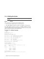
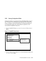
2.1
Invoking the SRM Console
When a system is powered up, the SRM console runs and either
remains running or passes control to another console or an
operating system. If the system is already running, invoke the
SRM console by shutting down the operating system or by
pressing the Halt button on the control panel.
If you are running Tru64 UNIX or OpenVMS Alpha operating system
•
The preferred method to invoke the SRM console is to shut down the
operating system according to the procedure described in your operating
system documentation.
•
An alternative method is to press the Halt button on the control panel.
Following one of these steps, the console prompt, >>>, will be displayed. You
are now at the SRM console.
If you are running AlphaBIOS
To switch to the SRM console, power cycle the system. The SRM console will
boot.
After you have performed tasks in the console mode, you must boot the
operating system with the boot command to go back to the operating mode.
2-2 DS10 / DS10L Console Reference
2.2
Commands
This section presents a command summary (Table 2–1), gives the
syntax for the console commands (Table 2–2), and explains the
special keystrokes and characters available in SRM console
mode (Table 2–3).
2.2.1
Command Summary
Table 2–1 Summary of SRM Console Commands
Command
Alphabios
boot
clear envar
clear password
continue
crash
deposit
edit
examine
Function
Loads and starts the AlphaBIOS console.
Loads and starts the operating system.
Resets an environment variable to its default value.
Sets the password to zero.
Resumes program execution.
Forces a crash dump at the operating system level.
Writes data to the specified address.
Invokes the console line editor on a RAM file or on the
nvram file (power-up script).
Displays the contents of a memory location, register, or
device.
halt
Halts the specified processor. (Same as stop.)
help
Displays information about the specified console
command.
initialize
lfu
login
Resets the system to a known state.
Runs the Loadable Firmware Update Utility.
Turns off secure mode, enabling access to all SRM console
commands during the current session.
SRM and AlphaBIOS Consoles
2-3
Continued on next page.
Table 2–1 Summary of SRM Console Commands (Continued)
Command
more
prcache
set envar
set host
set password
set secure
show envar
show config
show cpu
show device
show memory
show pal
show power
show version
stop
test
Function
Displays a file one screen at a time.
Utility that initializes and displays status of the
optional PCI NVRAM device.
Sets or modifies the value of an environment
variable.
Connects to an MSCP DUP server on a DSSI device.
Sets the console password for the first time or
changes an existing password.
Enables secure mode without requiring a restart of
the console.
Displays the state of the specified environment
variable.
Displays the configuration at the last system
initialization.
Displays the state of each processor in the system.
Displays a list of controllers and their devices in the
system.
Displays memory module information.
Displays the version of the privileged architecture
library code (PALcode).
Displays information about the power supply, system
and PCI fans, CPU fan, and temperature.
Displays the version of the console program.
Halts the processor. (Same as halt.)
Runs firmware diagnostics for the system.
2-4 DS10 / DS10L Console Reference
2.2.2
Commands: Syntax
Table 2–2 Syntax for SRM Console Commands
Parameter
Length
Case
Abbreviation
Options
Numbers
Attribute or Action
Up to 255 characters, not including the terminating
carriage return or any characters deleted as the
command is entered. A command longer than 80
characters and without the backslash character (see
Table 2–3) causes display of an error message.
Upper- or lowercase characters can be used for input.
Characters are displayed in the case in which they are
entered.
Only by dropping characters from the end of words. You
must enter the minimum number of characters to
identify the keyword unambiguously. Abbreviation of
environment variables is allowed with the show
command.
You can use command options, to modify the
environment, after the command keyword or after any
symbol or number in the command. See individual
command descriptions for examples.
Most numbers in console commands are in decimal
notation. Two exceptions, both of which use hexadecimal
notation, are addresses and numbers used in the deposit
command. The default radix can be overridden by
inserting %d before numbers you want to express in
decimal, %b before binary, %o before octal, or %x before
hexadecimal. Register names (for example, R0) are not
considered numbers and use decimal notation.
No
characters
A command line with no characters is a null command.
The console program takes no action and does not issue
an error message; it returns the console prompt. The
console supports command line recall and editing.
Spaces or
tabs
Multiple adjacent spaces and tabs are compressed and
treated as a single space. The console program ignores
leading and trailing spaces.
SRM and AlphaBIOS Consoles
2-5
2.2.3
Commands: Special Keystrokes and Characters
Table 2–3 Special Characters for SRM Console
Character
Return or
Enter
Backslash \
←Backspace
Delete
Help
Ctrl/A or F14
Ctrl/B or ↑
Function
Terminates a command line. No action is taken on a
command until it is terminated. If no characters are
entered and this key is pressed, the console just
redisplays the prompt.
Continues a command on the next line. Must be the last
character on the line to be continued.
Moves the cursor left one position, deleting one
character.
Deletes the previous character.
Entered at the console prompt without arguments, it
displays first-level help. When pressed after part of a
command, displays options available.
Toggles between insert and overstrike modes. The
default is overstrike.
Recalls previous command or commands. The last 16
commands are stored in the recall buffer.
Ctrl/C
Terminates the process that is running. Clears Ctrl/S;
resumes output suspended by Ctrl/O. When entered as
part of a command line, deletes the current line. Ctrl/C
has no effect as part of a binary data stream.
Ctrl/E
Moves the cursor to the end of the line.
Ctrl/F or →
Moves the cursor right one position.
Ctrl/H
Moves the cursor to the beginning of the line.
Ctrl/J
Deletes the previous word.
Continued next page.
2-6 DS10 / DS10L Console Reference
Character
Ctrl/O
Function
Stops output to the console terminal for the current
command. Toggles between enable and disable. The output
can be re-enabled by other means as well: when the console
prompts for a command, issues an error message, or enters
program mode, or when Ctrl/P is entered.
Ctrl/P
Halts the machine.
Ctrl/Q
Resumes output to the console terminal that was
suspended by Ctrl/S.
Ctrl/R
Redisplays the current line. Deleted characters are
omitted. This command is useful for hardcopy terminals.
Ctrl/S
Suspends output to the console terminal until Ctrl/Q is
entered. Cleared by Ctrl/C.
Ctrl/U
Deletes the current line.
*
"... "
#
Wildcarding for commands such as show.
Double quotes enable you to denote a string for
environment variable assignment.
Specifies that all text between it and the end of the line is a
comment. Control characters are not considered part of a
comment.
SRM and AlphaBIOS Consoles
2-7
2.3
Show Commands
Several commands are used to display the system configuration:
show config, show cpu, show device, show memory, show
network, show pal, show power, and show version.
2.3.1
Show Config
The show config command displays a list of devices found on the
system interconnect and I/O buses. This is the configuration at
the most recent initialization.
Syntax:
show config
Example 2–1 Show Config Command
>>> show config
AlphaServer DS10 466 MHz
SRM Console:
PALcode:
Processors
CPU 0
V5.7-0
OpenVMS PALcode V1.73-65, Tru64 UNIX PALcode V1.66-58
Alpha 21264-4 466 MHz
Bcache size: 2 MB
Core Logic
Cchip
Dchip
Pchip 0
DECchip 21272-CA Rev 2
DECchip 21272-DA Rev 2
DECchip 21272-EA Rev 2
TIG
Arbiter
Rev 2.1
Rev 3.30 (0x7E)
MEMORY
Array #
------0
Size
---------256 MB
SROM Revision: V1.14.208
Base Addr
--------000000000
Total Bad Pages = 0
Total Good Memory = 256 MBytes
PCI Hose 00
Bus 00
Slot 01: Acer Labs M1543C USB
Bus 00
Slot 03: Acer Labs M1543C PMU
Bus 00
Slot 07: Acer Labs M1543C
Bus 00
Slot 09: DE500-BA Network Controller
ewa0.0.0.9.0
Bridge to Bus 1, ISA
2-8 DS10 / DS10L Console Reference
08-00-2B-86-1B-BA
Bus 00
Bus 00
Slot 11: DE500-BA Network Controller
ewb0.0.0.11.0
Slot 13: Acer Labs M1543C IDE
dqa.0.0.13.0
dqa1.1.0.13.0
Slot 14: DEC PowerStorm
Bus 00
Slot 15: DECchip 21152-AA
Bus 00
Slot 16: QLogic ISP1020
pkc0.6.0.16.0
dkc0.0.0.16.0
dkc200.2.0.16.0
Slot 17: Mylex DAC960
dra.0.0.17.0
dra0.0.0.17.0
dra1.0.0.17.0
dra2.0.0.17.0
dra3.0.0.17.0
Slot 00: NCR 53C875
pka0.7.0.2000.0
dka100.1.0.2000.0
dka300.3.0.2000.0
dka500.5.0.2000.0
Slot 01: NCR 53C875
pkb0.7.0.2001.0
dkb0.0.0.2001.0
dkb200.2.0.2001.0
dkb400.4.0.2001.0
Slot 02: DE500-AA Network Controller
ewc0.0.0.2002.0
Bus 00
08-00-2B-86-1B-BB
CD-532E
Bridge to Bus 2, PCI
Bus 00
Bus 02
Bus 02
Bus 02
ISA
Slot
0
Device
Name
Type
0
1
2
3
4
5
MOUSE
KBD
COM1
COM2
LPT1
FLOPPY
Embedded
Embedded
Embedded
Embedded
Embedded
Embedded
Enabled
Yes
Yes
Yes
Yes
Yes
Yes
SCSI Bus ID 6
RZ1CB-BA
RZ1CB-BA
1
1
1
1
Member
Member
Member
Member
JBOD
JBOD
JBOD
JBOD
SCSI Bus ID 7
RZ1CB-CA
RZ1CB-CA
RZ1EF-AB
SCSI Bus ID 7
RZ1CB-CA
RZ1DB-CS
RZ1CB-CA
00-06-2B-00-26-1C
BaseAddr
60
60
3f8
2f8
3bc
3f0
IRQ
DMA
12
1
4
3
7
6
2
>>>
SRM and AlphaBIOS Consoles
2-9
2.3.2
Show Device
The show device command displays status for devices and
controllers in the system: SCSI and MSCP devices, the internal
floppy drive, and the network.
Syntax:
show device [controller_name]
controller_name
The controller name or abbreviation. When abbreviations
or wildcards are used, all controllers that match the type
are displayed. If no name is given, the display is a list of all
devices and controllers in the system.
Example 2–2 Show Device Command
>>> sho device
dka0.0.0.14.0
dka100.1.0.14.0
dqa0.0.0.13.0
dva0.0.0.0.0
ewa0.0.0.9.0
ewb0.0.0.11.0
pka0.7.0.14.0
>>>
DKA0
DKA100
DQA0
DVA0
EWA0
EWB0
PKA0
RZ2CA-KA N1H1
RZ2CA-KA N1H1
CD-532E- A 1.0A
08-00-2B-86-1F-71
08-00-2B-86-1F-70
SCSI Bus ID 7 5.57
An example of a device name is dka200.2.0.7.1. Table 2-4 shows the
interpretation of this device name.
2-10 DS10 / DS10L Console Reference
Table 2–4 Device Naming Convention
dk
a
Category
Description
Driver ID
Two-letter designator of port or class driver
dk
SCSI disk
dq
ATAPI CD-ROM
or IDE disk
mk
SCSI tape
dr
RAID set device
mu
DSSI tape
du
DSSI disk
pk
SCSI port
dv
Diskette drive
pu
DSSI port
ew
Ethernet port
fw
FDDI device
Storage adapter
ID
One-letter designator of storage adapter
(a, b, c...).
Device unit
number
Unique number (MSCP unit number). SCSI
unit numbers are forced to 100 X node ID.
2
Bus node number
Bus node ID.
0
Channel number
Used for multi-channel devices.
7
Logical slot
number
Corresponds to PCI slot number, as shown in
Table 2–5.
1
Hose number
0 — PCI 0
200
1 — PCI 1
SRM and AlphaBIOS Consoles
2-11
Table 2–5 PCI Address Assignments – DS10
Physical
Slot #
Logical
Slot #
PCI
ID_SEL
Description/Position
4
17
AD 28
64-bit slot (top slot)
3
16
AD 27
64-bit slot (second from top)
2
15
AD 26
64-bit slot (second from bottom)
1
14
AD 25
32-bit slot (bottom slot)
Table 2–6 PCI Address Assignment - DS10L
Physical
Slot #
Logical
Slot #
PCI
ID_SEL
Description/Position
1
17
AD 28
64-bit slot
2-12 DS10 / DS10L Console Reference
2.3.3
Show Memory
The show memory command displays information about each
memory bank: slot number, size in megabytes, and the starting
address.
Syntax:
show memory
Example 2–3 Show Memory Command
>>> show memory
Array #
------0
1
2
3
Size
---------128 MB
128 MB
128 MB
128 MB
Base Addr
--------000000000
008000000
010000000
018000000
Total Bad Pages = 0
Total Good Memory = 512 MBytes
>>>
2.3.4
Show PAL
The show pal command displays the versions of Tru64 UNIX and
OpenVMS PALcode. PALcode is the Alpha Privileged
Architecture Library code, written to support Alpha processors.
It implements architecturally defined processor behavior.
Syntax:
show pal
Example 2–4 Show PAL Command
>>> show pal
pal OpenVMS PALcode V1.73-65, Tru64 UNIX PALcode V1.66-58
>>>
SRM and AlphaBIOS Consoles
2-13
2.3.5
Show Power
The show power command displays status information about the
power supply, the system, PCI and CPU fans, and temperature.
This command is useful for displaying the error state of a Tru64
UNIX or OpenVMS system that shuts down because of a fan,
temperature, or power supply failure.
Syntax:
show power
Use this command to display information if the system can be restarted after a
shut down. . (If it cannot, use the RMC status command. See Chapter 3.)
Example 2–5 Show Power Command
>>> show power
Power Supply
System Fan
PCI Fan
CPU Fan
Temperature
Status
good
good
good
good
good
Current ambient temperature is 34 degrees C
System shutdown temperature is set to 55 degrees C
2 Environmental events are logged in nvram
Do you want to view the events? (Y/<N>) y
Total Environmental Events: 2 (2 logged)
1
2
000
000
0
0
0:00
0:00
Temperature, Fans, Power Supplies Normal
Temperature, Fans, Power Supplies Normal
Do you want to clear all events from nvram? (Y/<N>) y
>>>
2-14 DS10 / DS10L Console Reference
2.3.6
Show Version
The show version command displays the version of the SRM
console program that is installed on the system.
Syntax:
show version
Example 2–6 Show Version Command
>>> show version
version
>>>
V5.7-0 Jan 13 2000 14:24:16
SRM and AlphaBIOS Consoles
2-15
2.4
Creating a Power-Up Script
A special nonvolatile file named “nvram” is stored in EEROM,
and is always invoked during the power-up sequence. You can
create an nvram script to include any commands you want the
system to execute at power-up. You alter, create and edit the
nvram script using the SRM edit command. With edit, lines can
be added, overwritten, or deleted.
Syntax:
edit file
where file is the name of the file to be edited.
The editing commands are:
Help
List
Renumber
Displays the brief help file.
Lists the current file prefixed with line numbers.
Renumbers the lines of the file in increments of 10.
Exit
Leaves the editor and closes the file, saving all changes.
Quit
Leaves the editor and closes the file without saving changes.
Nn
Nn text
Deletes line number nn.
Adds or overwrites line number nn with text.
2-16 DS10 / DS10L Console Reference
NOTE: It is possible to disable the system by editing the nvram script. For
example, if you include the initialize command in the script, the
system will go into an endless loop. To fix this, press the Halt button
while the system is powering up. You can then edit the script to delete
the offending command.
Example 2–7 shows how to modify the user-created power-up script, “nvram.”
The pound sign (#) indicates explanatory comments. In this example the script
is edited to include a command that allows you to boot the Tru64 UNIX
operating system over the network.
Example 2–7 Editing the nvram Script
>>> edit nvram
editing ‘nvram’
0 bytes read in
*10 set ewa0_protocols bootp
*list
10 set ewa0_protocols bootp
*exit
27 bytes written out to nvram
>>> nvram
#Modify user power-up script, nvram.
#List current file with line numbers.
#Close file and save changes.
#Execute the script.
To clear the script, enter line numbers without any text. This deletes the lines.
See Example 2–8.
Example 2–8 Clearing the nvram Script
>>> edit nvram
editing ‘nvram’
20 bytes read in
*10
*exit
0 bytes written out to nvram
>>>
SRM and AlphaBIOS Consoles
2-17
2.5
Booting the Operating System
The boot command is used to boot the operating system. The boot
command initializes the processor, loads a program image from
the specified boot device, and transfers control to that image.
Syntax: boot [-file filename] [-flags [value]] [-halt]
[-protocols enet_protocol] [boot_dev]
-file filename
The boot file.
-flags [value]
Specifies additional information to the loaded image or
operating system. In Tru64 UNIX, specifies boot flags.
In OpenVMS, specifies system root number and boot
flags. This qualifier overrides the setting of the
boot_osflags environment variable. See the
boot_osflags environment variable for a list of
settings and their meanings.
-halt
Forces the bootstrap operation to halt and invoke the
console program once the bootstrap image is loaded and
page tables and other data structures are set up.
Console device drivers are not shut down. Transfer
control to the image by entering the continue
command.
-protocols
enet_protocol
Either mop (default) or bootp. This qualifier overrides
the setting of the ew*0_protocols environment
variable.
boot_dev
A device path or list of devices from which the console
program attempts to boot, or a saved boot specification
in the form of an environment variable. This qualifier
overrides the setting of the bootdef_dev environment
variable. Use the bootdef_dev environment variable
to define the default boot device string.
2-18 DS10 / DS10L Console Reference
Example 2–9 Boot Command
>>> b dkc0
(boot dkc0.0.0.16.0 -flags 0)
block 0 of dkc0.0.0.16.0 is a valid boot block
reading 898 blocks from dkc0.0.0.16.0
bootstrap code read in
base = 200000, image_start = 0, image_bytes = 70400
initializing HWRPB at 2000
initializing page table at ffb6000
initializing machine state
setting affinity to the primary CPU
jumping to bootstrap code
OpenVMS (TM) Alpha Operating System, Version V7.1-2
%SYSINIT-I- waiting to form or join an OpenVMS Cluster
%VMScluster-I-LOADSECDB, loading the cluster security database
%EWA0, Fast(100baseTX) mode set by console
%EWB0, Fast(100baseTX) mode set by console
. . .
%CNXMAN, Completing VMScluster state transition
$! Copyright (c) 1998 Digital Equipment Corporation. All rights reserved.
%STDRV-I-STARTUP, OpenVMS startup begun at 23-APR-1999 11:31:48.97
%MSCPLOAD-I-CONFIGSCAN, enabled automatic disk serving
. . .
The OpenVMS system is now executing the site-specific startup commands.
. . .
Welcome to OpenVMS (TM) Alpha Operating System, Version V7.1-2
Username:
SRM and AlphaBIOS Consoles
2-19
2.6
Configuring a PCI NVRAM Module
The prcache command is used for system configuration to check
PCI NVRAM configuration information and battery status, to
clear data from the NVRAM module, and to set the date of the
next battery replacement. The command is used only with
Tru64 UNIX systems.
Syntax:
prcache -{f,z,b}
-f
Checks configuration information and battery status.
-z
Clears valid data; writes zeros to memory.
-b
Sets the date (month and year) for battery replacement.
Example 2–10 Prcache Command
>>> prcache -f
PCI NVRAM Disk Cache: passed
Size:
2MB
PCI Memory Address: 40000000
System ID: 12000000
State: - not valid
Battery Status: good (Charging)
Battery Disconnect Circuit Status: enabled
>>> prcache -z
This command will zero the PCI NVRAM Disk Cache
Do you really want to continue [Y/N] ? : y
clearing disk cache
>>>
2-20 DS10 / DS10L Console Reference
2.7
Testing the System
The test command runs console-based exercisers for devices in
the system. Ctrl/C can abort testing.
Syntax:
-t time
-q
test [-t time] [-q] [option]
Specifies the run time in seconds. The default for system test is
120 seconds (2 minutes).
Disables the display of status messages as exerciser processes
are started and stopped during testing. Sets the environment
variable d_verbose to zero.
Example 2–11 Test Command
>>> test
environment variable t_cnt created
System test, runtime 150 seconds
Type ^C if you wish to abort testing once it has started
Default zone extended at the expense of memzone.
Use INIT before booting
Testing Ethernet device(s)
Testing VGA
Testing Memory
Testing IDE/ATAPI disks (read-only)
Testing SCSI disks (read-only)
Testing DKA* devices (read-only)..
No other SCSI disks to test
Testing floppy drive (dva0, read-only)
No diskette present, skipping floppy test
SRM and AlphaBIOS Consoles
2-21
ID
-------00001ae5
00001aea
00001b07
00001b54
00001b74
00001b7b
ID
-------00001ae5
00001aea
00001b07
00001b54
00001b74
00001b7b
ID
-------00001ae5
00001aea
00001b07
00001b54
00001b74
00001b7b
ID
-------00001ae5
00001aea
00001b07
00001b54
00001b74
00001b7b
ID
-------00001ae5
00001aea
00001b07
00001b54
00001b74
00001b7b
ID
-------00001ae5
00001aea
00001b07
00001b54
00001b74
00001b7b
Program
-----------memtest
memtest
memtest
exer_kid
exer_kid
exer_kid
Program
-----------memtest
memtest
memtest
exer_kid
exer_kid
exer_kid
Program
-----------memtest
memtest
memtest
exer_kid
exer_kid
exer_kid
Program
-----------memtest
memtest
memtest
exer_kid
exer_kid
exer_kid
Program
-----------memtest
memtest
memtest
exer_kid
exer_kid
exer_kid
Program
-----------memtest
memtest
memtest
exer_kid
exer_kid
exer_kid
Device
-----------memory
memory
memory
dqa0.0.0.13.
dka0.0.0.14.
dka100.1.0.1
Device
-----------memory
memory
memory
dqa0.0.0.13.
dka0.0.0.14.
dka100.1.0.1
Device
-----------memory
memory
memory
dqa0.0.0.13.
dka0.0.0.14.
dka100.1.0.1
Device
-----------memory
memory
memory
dqa0.0.0.13.
dka0.0.0.14.
dka100.1.0.1
Device
-----------memory
memory
memory
dqa0.0.0.13.
dka0.0.0.14.
dka100.1.0.1
Device
-----------memory
memory
memory
dqa0.0.0.13.
dka0.0.0.14.
dka100.1.0.1
Pass Hard/Soft Bytes Written
------ --------- ------------4
0
0
310378496
4
0
0
306184192
3
0
0
310378496
0
0
0
0
0
0
0
0
0
0
0
0
Pass Hard/Soft Bytes Written
------ --------- ------------6
0
0
549453824
6
0
0
545259520
6
0
0
545259520
0
0
0
0
0
0
0
0
0
0
0
0
Pass Hard/Soft Bytes Written
------ --------- ------------8
0
0
780140544
8
0
0
780140544
8
0
0
780140544
0
0
0
0
0
0
0
0
0
0
0
0
Pass Hard/Soft Bytes Written
------ --------- ------------11
0
0
1019215872
10
0
0
1019215872
10
0
0
1019215872
0
0
0
0
0
0
0
0
0
0
0
0
Pass Hard/Soft Bytes Written
------ --------- ------------13
0
0
1254096896
13
0
0
1249902592
12
0
0
1254096896
0
0
0
0
0
0
0
0
0
0
0
0
Pass Hard/Soft Bytes Written
------ --------- ------------15
0
0
1488977920
15
0
0
1484783616
14
0
0
1488977920
0
0
0
0
0
0
0
0
0
0
0
0
2-22 DS10 / DS10L Console Reference
Bytes Read
----------310378496
306184192
310378496
215040
8732672
8732672
Bytes Read
----------549453824
545259520
545259520
421888
14434304
14434304
Bytes Read
----------780140544
780140544
780140544
631808
20168704
20168704
Bytes Read
----------1019215872
1019215872
1019215872
835584
27066368
27066368
Bytes Read
----------1254096896
1249902592
1254096896
1043456
32800768
32784384
Bytes Read
----------1488977920
1484783616
1488977920
1241088
39665664
39649280
ID
Program
Device
Pass Hard/Soft
-------- ------------ ------------ ------ --------00001ae5
memtest memory
17
0
0
00001aea
memtest memory
17
0
0
00001b07
memtest memory
16
0
0
00001b54
exer_kid dqa0.0.0.13.
0
0
0
00001b74
exer_kid dka0.0.0.14.
0
0
0
00001b7b
exer_kid dka100.1.0.1
0
0
0
Test time has expired...
Bytes Written Bytes Read
------------- ----------1723858944
1723858944
1723858944
1723858944
1723858944
1723858944
0
1445888
0
45350912
0
45350912
System test complete
>>>
Type cat el to show the log if you wish.
SRM and AlphaBIOS Consoles
2-23
2.8
2.8.1
Set Commands
Set Password
The set password command sets the console password for the
first time or changes an existing password. It is necessary to set
the password only if the system is going to operate in secure
mode.
Syntax:
set password
The password length must be between 15 and 30 alphanumeric characters.
If a password has not been set and the set password command is issued, the
console prompts for a password and verification.
If a password has been set and the set password command is issued, the
console prompts for the new password and verification, then prompts for the old
password. The password is unchanged if the validation password entered does
not match the existing password in the NVRAM.
Example 2–12 Set Password Command
>>> set password
Please enter the password:
# Password is not echoed.
Please enter the password again: # Validation is not echoed.
>>>
>>> set password
# Changing a password.
Please enter the password:
Please enter the password again:
Now enter the old password:
>>>
>>> set password
# Password entered is
Please enter the password:
# too short.
Password length must be between 15 and 30 characters
>>>
2-24 DS10 / DS10L Console Reference
2.8.2
Set Secure
The set secure command enables secure mode without requiring
a restart of the console. If the password has been set, the console
will be secured and only a small subset of commands can be
performed. If a password has not been set, you are prompted to
do so.
Syntax:
set secure
Example 2–13 Set Secure Command
>>> set secure
# In this example a password
# has been set.
Console is secure. Please login.
>>> b dkb0
Console is secure - parameters are not allowed.
>>> login
Please enter the password:
# Password is not echoed.
>>> b dkb0
(boot dkb0.0.0.3.1)
.
.
>>> set secure
# Password has not been set.
Secure not set. Please set the password.
>>>
SRM and AlphaBIOS Consoles
2-25
2.9
Secure Mode
When the console is in secure mode, the only commands
recognized are boot, login, continue, and start. Placing the console
in secure mode ensures that unauthorized persons cannot gain
access to the system. The commands for console security are set
password, clear password, and set secure. The login command
turns off security features during the current console session.
The boot command does not accept command line parameters in secure mode.
The console boots using the environment variables stored in NVRAM
(boot_file, bootdef_dev, boot_flags). After a successful boot, the console is
secured if there is a valid password.
The start and continue commands are valid on a secure console. After either
command is executed, the console is secured if there is a valid password. This
prevents an intruder from accessing the system.
2.9.1
Login Command and Secure Mode
The login command turns off the security features, enabling
access to all SRM console commands during the current session.
The system automatically returns to secure mode as soon as the
boot, continue, or start command is entered or when the system is
initialized.
When the login command is entered, the user is prompted for the current
system password. If a password has not been set, a message is displayed
indicating that there is no password in NVRAM. If a password has been set, this
prompt is displayed:
Please enter the password:
If the password entered matches the password in NVRAM when the prompt is
redisplayed, the console is no longer in secure mode and all console commands
can be performed.
NOTE:
If you enter the login command when a halt assertion exists, the
command fails, even if you enter the correct password. See Section 1.10
for information on halt assertion.
2-26 DS10 / DS10L Console Reference
Example 2–14 Secure Mode and Login Command
>>> login
# System is not in secure mode.
>>>
Secure not set. Please set the password.
>>> login
Please enter the password:
>>>
# System is in secure mode.
# Password is not echoed.
>>> login
Please enter the password:
# System is in secure mode.
# Incorrect password is
# entered.
Invalid password
>>>
2.9.2
Clear Password
The clear password command clears the password environment
variable, setting it to zero. This command is used when you want
access to all the SRM console commands, but the system is in
secure mode. In order to use clear password, you must know the
current password.
Example 2–15 Clear Password Command
>>> clear password
Please enter the password:
Password successfully cleared.
>>>
>>> clear password
Please enter the password:
Console is secure
>>>
# Password is not echoed.
# Invalid password entered.
SRM and AlphaBIOS Consoles
2-27
2.9.3
Resetting the Password
If you have forgotten the current password, clear the password as follows:
From the Local Console Terminal
1. Enter the login command: >>> login
2. At the Enter Password: prompt, press the Halt button, then press the Return
key.
The password is now cleared and the console cannot be put into secure mode
unless a new password is set.
From the RMC
1. Enter the login command: >>> login
2. At the Enter Password: prompt, enter the RMC escape sequence.
3. At the RMC>>> prompt, enter the halt command and then the quit
command:
RMC>>> halt
RMC>>> quit
4. At the SRM console, clear the password:
>>> clear password
2-28 DS10 / DS10L Console Reference
2.10 Stopping and Starting CPU
The halt (or stop) command stops program execution on a CPU
that is still running a booted program.
Syntax:
halt (or stop) 0
where 0 is the number of the CPU to halt.
For the DS10 system, this command has no effect because the single CPU is
halted when the system is at the console prompt.
2.11 Updating Firmware
The lfu command is used to update firmware from the SRM
console prompt. The lfu command starts the Loadable Firmware
Update (LFU) Utility.
The syntax is: lfu
Example 2–16 Lfu Command
>>> lfu
Checking dqa0.0.0.13.0 for the option firmware files. . .
Checking dva0 for the option firmware files. . .
Option firmware files were not found on CD or floppy.
If you want to load the options firmware,
please enter the device on which the files are located(ewa0),
or just hit <return> to proceed with a standard console update: dva0
Please enter the name of the options firmware files list, or
Hit <return> to use the default filename (ds10fw.txt) :
Copying ds10fw.txt from dva0. . .
Copying PC264NT.ROM from dva0. . .
Copying DS10SRM.ROM from dva0. . .
SRM and AlphaBIOS Consoles
2-29
***** Loadable Firmware Update Utility *****
-----------------------------------------------------------------Function
Description
-----------------------------------------------------------------Display
Displays the system’s configuration table.
Exit
Done exit LFU (reset).
List
Lists the device, revision, firmware name, and update
revision.
Readme
Lists important release information.
Update
Replaces current firmware with loadable data image.
Verify
Compares loadable and hardware images.
? or Help
Scrolls this function table.
-----------------------------------------------------------------UPD> update *
Confirm update on:
nt
srm
[Y/(N)]y
WARNING: updates may take several minutes to complete for each device.
DO NOT ABORT!
nt
Updating to 5.70...
srm
Updating to 5.7-0...
Verifying 5.70...
PASSED.
Verifying 5.7-0...
PASSED.
UPD> exit
NOTE: If the system has been shut down from a booted program (most
commonly, the operating system) or in some other way halted back to
the SRM console, the system must be reset before running LFU.
See Chapter 1 for more information about LFU.
2-30 DS10 / DS10L Console Reference
2.12 Forcing a System Crash Dump
The crash command forces a crash dump at the operating system
level. This command is used when an error has caused the
system to hang and can be halted with the Halt button or the
RMC halt command. This command restarts the operating
system and forces a crash dump to the selected device.
Syntax:
crash [device]
where device is the name of the device to which the crash dump is written.
Example 2–17 Crash Command
>>> crash
CPU 0 restarting
DUMP: 401408 blocks available for dumping.
DUMP: 38535 required for a partial dump.
DUMP: 0x805001 is the primary swap with 401407, start our last 38534
: of dump at 362873, going to end (real end is one more, for
header)
DUMP.prom: dev SCSI 1 3 0 4 400 0 0, block 131072
DUMP: Header to 0x805001 at 401407 (0x61fff)
DUMP.prom: dev SCSI 1 3 0 4 400 0 0, block 131072
DUMP: Dump to 0x805001: ..................: End 0x805001
DUMP.prom: dev SCSI 1 3 0 4 400 0 0, block 131072
DUMP: Header to 0x805001 at 401407 (0x61fff)
succeeded
halted CPU 0
halt code = 5
HALT instruction executed
PC = fffffc00004e2d64
>>>
SRM and AlphaBIOS Consoles
2-31
2.13 Using Environment Variables
Environment variables pass configuration information between
the console and the operating system. Their settings determine
how the system powers up, boots the operating system, and
operates.
You issue an init command to activate a new
environment variable.
Environment variables are set or changed with the set envar command (where
envar is a placeholder for the environment to be changed) and set to default
values with the set -default envar command. Their values are viewed with the
show envar command. User-defined nonvolatile environment variables are
created with the edit command described in Section 2.4. Section 2-18 describes
the predefined SRM console environment variables in detail.
2.13.1
set envar
The set command sets or modifies the value of an environment
variable. It can also be used to create a new environment
variable if the name used is unique. Environment variables are
used to pass configuration information between the console and
the operating system. The setting of these variables determines
how the system powers up, boots the operating system, and
operates.
Syntax:
-default
set [-default] envar value
Restores an environment variable to its default setting.
envar
The name of the environment variable to be displayed. The
wildcard * displays all environment variables, which are:
console, kbd_hardware_type, language, ocp_text
and os_type
value
The new value of the environment variable.
Whenever you modify the value of any environment variables, the new value
takes effect only after you reset the system by pressing the Halt/Reset button or
issuing the initialize command.
2-32 DS10 / DS10L Console Reference
2.13.2
show envar
The show envar command displays the current value (or setting)
of an environment variable.
Syntax:
envar
show envar
The name of the environment variable to be displayed. The
wildcard * displays all environment variables, which are:
console, kbd_hardware_type, language, ocp_text
and os_type.
Example 2–18 Setting and Showing Environment Variables
>>> show console
console
>>> set console serial
>>> show console
console
>>> init
graphics
serial
# The system must be init’ed for
the new parameters to take effect
Example 2–19 Creating a User-Defined Environment Variable
>>> edit nvram
editing ‘nvram’
0 bytes read in
*10 set mopv3_boot 1
*exit
17 bytes written out to nvram
>>>
In Example 2–19 the nvram script is edited so that an environment variable
called “mop3_boot” is created and set to 1 on each power-up. By default, MOP
boot sends four MOP V4 requests before defaulting to MOP V3. This usercreated environment variable forces the SRM console to bypass MOP V4
requests. This speeds up MOP booting on networks with MOP V3 software.
SRM and AlphaBIOS Consoles
2-33
2.14 Depositing and Examining Data
The deposit command stores data in a specified location. The
examine command displays the contents of a memory location, a
register, or a device.
Syntax: deposit [-{b,w,l,q,o,h}] [-{n value, s value}] [space:] address data
examine [-{b,w,l,q,o,h}] [-{n value, s value}] [space:] address
-b
Defines data size as byte.
-w
Defines data size as word.
-l (default)
Defines data size as longword.
-q
Defines data size as quadword.
-o
Defines data size as octaword.
-h
Defines data size as hexword.
-d
Instruction decode (examine command only)
-n value
The number of consecutive locations to modify.
-s value
The address increment size. The default is the data size.
space:
Device name (or address space) of the device to access.
address
Offset within a device to which data is deposited. Can be:
dev_name
A device name.
fpr- name
The floating-point register set; name
is F0 to F31.
gpr- name
The general register set; name is R0
to R31.
ipr- name
The internal processor registers.
pt- name
The PALtemp register set; name is
PT0 to PT23.
pmem
Physical memory (default).
vmem
Virtual memory.
2-34 DS10 / DS10L Console Reference
data
Data to be deposited.
Symbolic forms can be used for the address. They are:
pc
The program counter. The address space is set to GPR.
+
The location immediately following the last location referenced in a
deposit or examine command. For physical and virtual memory,
the referenced location is the last location plus the size of the
reference (1 for byte, 2 for word, 4 for longword). For other address
spaces, the address is the last referenced address plus 1.
-
The location immediately preceding the last location referenced in a
deposit or examine command. Memory and other address spaces
are handled as above.
*
The last location referenced in a deposit or examine command.
@
The location addressed by the last location referenced in a deposit
or examine command.
The deposit command stores data in the location specified. If no options are
given with a deposit command, the system uses the options from the preceding
deposit command.
If the specified value is too large to fit in the data size listed, the console ignores
the command and issues an error response. If the data is smaller than the data
size, the higher order bits are filled with zeros. The syntax is shown below.
The examine command displays the contents of a memory location, a register,
or a device.
If no options are given with an examine command, the system uses the options
from the preceding examine command. If conflicting address space or data
sizes are specified, the console ignores the command and issues an error.
For data lengths longer than a longword, each longword of data should be
separated by a space.
Example 2–20 Deposit Command
>>> dep -b -n 1ff pmem:0 0
# Clear 1st 512 bytes of physical mem.
SRM and AlphaBIOS Consoles
2-35
>>> d -l -n 3 vmem:1234 5
# Deposit 5 into four longwords starting
# at virtual memory address 1234.
>>> d -n 8 r0 ffffffff
# Load GPRs R0 through R8 with -1.
>>> d -l -n 10 -s 200 pmem:0 8
# Deposit 8 in the 1 longword of the
# first 17 pages in physical memory
>>> d -l pmem:0 0
# Deposit 0 to physical mem address 0.
>>> d + ff
# Deposit FF to physical mem address 4.
>>> d scbb 820000
# Deposit 820000 to SCBB.
st
Example 2–21 Examine Command
>>> examine pc
PC psr: 0 (
PC)
# Examine the program counter.
0000000000001170
>>> examine sp
gpr:
F0 (
R30)
# Examine the stack pointer.
0000000000072A60
>>> e -n 6 r4
grp: 20 (
R4) 0000000000005000
grp: 28 (
R5) 000000000FFFE000
grp: 30 (
R6) 00000003F8000C00
grp: 38 (
R7) 0000000053F761AE
grp: 40 (
R8) 0000010000000000
grp: 48 (
R9) 00000003F7800100
grp: 50 (
R10) 00000000000C7FFC
>>> examine pmem:400EC
pmem: 400EC A49D0078A47D0070
# Examine register R4 & the next 6 registers.
# Examine physical memory.
2-36 DS10 / DS10L Console Reference
2.15 Reading a File
The more command displays a file one screen at a time.
Syntax:
more [file...]
where file is the name of the file to be displayed.
The more command is similar to that used in the MS-DOS and UNIX operating
systems. It is useful for displaying output that scrolls too quickly to be viewed.
For example, when you power up the system, the system startup messages
scroll, and the messages are logged to an event log
When the >>> prompt displays, you can use the more command to display the
contents of the event log file.
Example 2–22 More Command
>>> more el
# Display SRM console’s event log one screen at a time.
. . .
--More-- (SPACE - next page, ENTER - next line, Q - quit)
>>> help * | more
# Display online help one screen at a time.
. . .
--More-- (SPACE - next page, ENTER - next line, Q - quit)
SRM and AlphaBIOS Consoles
2-37
2.16 Initializing the System
The initialize command resets the system and executes powerup tests.
Syntax:
initialize
After self-tests are executed, the system autoboots unless:
•
A halt assertion condition exists (see Section 1.10) –or–
•
The auto_action environment variable is set to halt (see Section 2.18.1).
If the auto_action environment variable is set to boot or restart and no halt
assertion condition exists, the system autoboots. In all other cases, the system
stops in console mode and does not attempt to boot.
Example 2–23 Initialize Command
>>> init
Initializing...
256 Meg of system memory
probing hose 0, PCI
probing PCI-to-ISA bridge, bus 1
probing PCI-to-PCI bridge, bus 2
bus 0, slot 9 -- ewa -- DE500-BA Network Controller
bus 0, slot 11 -- ewb -- DE500-BA Network Controller
bus 0, slot 13 -- dqa -- Acer Labs M1543C IDE
bus 0, slot 13 -- dqb -- Acer Labs M1543C IDE
bus 0, slot 14 -- vga -- DEC PowerStorm
bus 2, slot 0 -- pka -- NCR 53C875
bus 2, slot 1 -- pkb -- NCR 53C875
bus 2, slot 2 -- ewc -- DE500-AA Network Controller
bus 0, slot 16 -- pkc -- QLogic ISP1020
bus 0, slot 17 -- dra -- Mylex DAC960
Testing the System
Testing the Disks (read only)
Testing the Network
System Temperature is 34 degrees C
CPU 0
Alpha 21264-4 466 MHz
SROM Revision: V1.8.208
TIG
Rev 2.1
Arbiter
Rev 3.30 (0x7E)
Array #
Size
Base Addr
---------------- --------0
512 MB
000000000
1
512 MB
020000000
2
128 MB
050000000
3
256 MB
040000000
Total Bad Pages = 0
Total Good Memory = 1408 MBytes
AlphaServer DS10 466 MHz Console V5.7-2 Jan 13 2000 14:24:16
>>>
2-38 DS10 / DS10L Console Reference
2.17 Finding Help
The help command displays basic information about the use of
console commands when the system is in console mode.
Syntax:
Command . . .
help [command . . . ]
Command or topic for which help is requested. The options are:
None
Displays the complete list of commands for
which you can receive help.
Command_name
Displays information about the console
command.
Argument_string
(such as “sh”)
Displays information about all commands
that begin with that string.
Example 2–24 Help Command
>>> help set
NAME
set
FUNCTION
Set an option or modify the value of an environment
variable.
SYNOPSIS
set <option> <value> or <envar> [-] <value>
where
<option>={host,mode}
where
<envar>={auto_action,bootdef_dev,boot_osflags,...}
[-default]
SRM and AlphaBIOS Consoles
2-39
2.18 Environment Variable Summary
Environment variables pass configuration information between
the console and the operating system. Their settings determine
how the system powers up, boots the operating system, and
operates. Environment variables are set or changed with the set
envar command and returned to their default values with the
clear envar command. Their values are viewed with the show
envar command.
Table 2–7 lists the environment variables. Detailed descriptions follow. The
environment variables are specific to the SRM console.
Table 2–7 Environment Variable Summary
Environment Variable
auto_action
Function
Specifies the console’s action at power-up, a failure,
or a reset.
bootdef_dev
Specifies the default boot device string.
boot_osflags
Specifies the default operating system boot flags.
com*_baud
console
cpu_enabled
ew*0_mode
Changes the default baud rate of the COM1 or COM2
serial port.
Specifies the device on which power-up output is
displayed (serial terminal or graphics monitor).
Enables or disables a specific secondary CPU.
Specifies the connection type of the default Ethernet
controller.
ew*0_protocols
Specifies network protocols for booting over the
Ethernet controller.
kbd_hardware_
type
Specifies the default console keyboard type.
language
Specifies the console keyboard layout.
2-40 DS10 / DS10L Console Reference
Table 2–7 Environment Variable Summary (Continued)
Environment Variable
ocp_text
os_type
Function
Overrides the default OCP display text with specified
text.
Specifies the operating system. Valid entries are:
openvms, and unix.
password
A password stored in the NVRAM used to secure the
console.
pci_parity
Disables or enables parity checking on the PCI bus.
pk*0_fast
pk*0_host_id
pk*0_soft_term
tt_allow_login
Enables fast SCSI mode.
Specifies the default value for a controller host bus
node ID.
Enables or disables SCSI terminators on systems
that use the QLogic ISP1040 SCSI controller.
Enables or disables login to the SRM console
firmware on other console ports.
SRM and AlphaBIOS Consoles
2-41
2.18.1
auto_action
Specifies the action the console takes any time the system
powers up, fails, or resets. When the setting involves autoboot,
the system boots from the default boot device specified by the
value of the bootdef_dev environment variable.
Syntax:
set auto_action value
where value can be:
halt
The system remains in console mode after power-up or a system
crash.
boot
The system boots automatically when it is turned on and halts after
a system failure.
restart
The system boots automatically when it is turned on or after it fails.
NOTE: If a halt assertion exists, the console ignores the auto_action setting and
halts at the SRM console. See Section 1.10 for information on halt
assertion.
2.18.2
bootdef_dev
The bootdef_dev environment variable specifies one or more
devices for booting the operating system. When more than one
device is listed, the system searches in the order listed and boots
from the first device with operating system software.
Syntax:
set bootdef_dev boot_device
Where boot_device is the name of the device on which the system software has
been loaded. To specify more than one device, separate the names with commas.
Enter the command show bootdef_dev to display the current default boot
device. Enter the command show device for a list of all devices in the system.
2-42 DS10 / DS10L Console Reference
2.18.3
boot_osflags
The boot_osflags environment variable passes information to the
boot command. That information is dependent on the operating
system to be booted.
Syntax for Tru64 UNIX:
set boot_osflags flags_value
where flags_value can be:
a
Load operating system software from the specified boot device
(autoboot). Boot to multi-user mode.
i
Prompt for the name of a file to load and other options (boot
interactively). Boot to single-user mode.
s
Stop in single-user mode. Boots /vmunix to single-user mode and
stops at the # (root) prompt.
D
Full dump; implies “s” as well. By default, if Tru64 UNIX crashes, it
completes a partial memory dump. Specifying “D” forces a full
dump if the system crashes.
Syntax for OpenVMS: set boot_osflags root_number, boot_flags
Where root_number is the directory number of the system disk on which
OpenVMS files are located. For example:
root_number
Root Directory
0 (default)
[SYS0.SYSEXE]
1
[SYS1.SYSEXE]
2
[SYS2.SYSEXE]
3
[SYS3.SYSEXE]
And boot_flags are the hexadecimal value of the bit number or numbers set. To
specify multiple boot flags, add the flag values (logical OR). See Table 2–8.
SRM and AlphaBIOS Consoles
2-43
Table 2–8 Settings for boot_osflags Bootflags (OpenVMS)
Flags_Value
Bit Number
Meaning
1
0
Bootstrap conversationally (enables you to
modify SYSGEN parameters in SYSBOOT).
2
1
Map XDELTA to running system.
4
2
Stop at initial system breakpoint.
8
3
Perform diagnostic bootstrap.
10
4
Stop at the bootstrap breakpoints.
20
5
Omit header from secondary bootstrap
image.
80
7
Prompt for the name of the secondary
bootstrap file.
100
8
Halt before secondary bootstrap.
10000
16
Display debug messages during booting.
20000
17
Display user messages during booting.
2-44 DS10 / DS10L Console Reference
2.18.4
com1_baud
The default baud rate for the system is 9600. With the com1_baud
environment variable, you can set the baud rate to match that of
the device connected to the port.
Syntax:
set com1_baud baud_value
where baud_value is the new baud rate. A list of possible values is displayed by
attempting to set this environment variable to an unacceptable value (for
example, set com2_baud xxx).
NOTE: Disable the RMC to select a baud rate other than 9600. See Chapter3.
You will be asked to confirm the change, as shown in Example 2–25.
Example 2–25 Changing Baud Rate
>>> set com1_baud 19200
Embedded Remote Console only supports 9600 baud. Continue? (Y/[N]) n
bad value - com1_baud not modified
>>>
2.18.5
com1_mode
The set com1_mode command sets the bypass modes of the
remote management console (see Chapter 3)
For modem connections, you can set the com1_mode variable to allow data to
partially or completely bypass the RMC. The bypass modes are snoop mode, soft
bypass mode, and firm bypass mode.
•
In snoop mode, you can type an escape sequence to enter RMC mode. RMC
mode provides a command-line interface for issuing commands to monitor
and control the system.
•
In soft bypass mode, you cannot enter RMC mode. But if an alert condition
or loss of carrier occurs, the RMC switches into snoop mode. From snoop
mode you can enter RMC mode.
SRM and AlphaBIOS Consoles
2-45
•
In firm bypass mode, you cannot enter RMC mode. To enter RMC mode
from firm bypass mode, reset the com1_mode variable from the SRM
console.
Syntax:
set com1_mode value
where value can be:
snoop
Data partially bypasses RMC, but RMC taps into the data lines
and listens passively for the RMC escape sequence.
soft_bypass
Data bypasses RMC, but RMC switches automatically into snoop
mode if an alert condition or loss of carrier occurs.
firm_bypass
Data bypasses RMC. RMC is effectively disabled.
Example:
>>> set com1_mode
COM1_MODE (SNOOP, SOFT_BYPASS, FIRM_BYPASS)
2.18.6
console
The console terminal can be either a graphics monitor or a
serial terminal. The console environment variable specifies
which is used. Whenever you change the value of console, you
must reset the system by pressing the Halt/Reset button or
issuing the initialize command.
Syntax:
set console output_device
where output_device can be:
graphics
(default)
serial
The console terminal is a graphics monitor or a device connected
to the VGA or TGA module.
The console terminal is the device connected to the COM1 port.
2-46 DS10 / DS10L Console Reference
2.18.7
ew*0_mode
Sets an Ethernet controller to run an AUI, ThinWire, or twistedpair Ethernet network. The default is auto-sense. For the fast
setting, the device defaults to fast.
Syntax:
set ew*0_mode value
where value can be:
aui
auto-sense
Device type is AUI.
Device type is sensed by the console.
twisted-pair
Device type is 10BaseT (twisted pair).
fast duplex,
twisted-pair
Device type is duplex 10BaseT.
fast
fast FD
BNC
auto-negotiate
2.18.8
Device type is fast SCSI.
Device type is fast full duplex SCSI.
Device type is BNC.
DE500-BA
ew*0_protocols
Enables network protocols for booting and other functions.
Syntax:
set ew*0_protocols protocol_value
where protocol_value can be:
mop (default)
bootp
bootp,mop
Sets the network protocol to mop (Maintenance Operations
Protocol), the setting typically used with the OpenVMS
operating system.
Sets the network protocol to bootp, the setting typically
used with the Tru64 UNIX operating system.
When both are listed, the system attempts to use the mop
protocol first, regardless of which is listed first. If not
successful, it then attempts the bootp protocol.
SRM and AlphaBIOS Consoles
2-47
2.18.9
kbd_hardware_type
Used only on systems with the language variant 3C (Français),
this environment variable sets the keyboard hardware type as
either PCXAL or LK411 and enables the system to interpret the
terminal keyboard layout correctly.
Syntax:
set kbd_hardware_type keyboard_type
where keyboard_type can be:
pcxal
(default)
lk411
Selects the default keyboard hardware type.
Selects the LK411 keyboard layout for use with language
variant 3C (Français).
Whenever you change the value of kbd_hardware_type, you must reset the
system by pressing the Halt/Reset button or issuing the initialize command.
2.18.10 language
Specifies the keyboard layout, which is language dependent.
The setting of the language environment variable must match the
language of the keyboard variant. Whenever you change the
value of language, you must reset the system by pressing the
Halt/Reset button or issuing the initialize command.
Syntax:
set language language_code
where language_code can be:
0
30
32
34
36
38
3A
3C
3E
No language (cryptic)
Dansk (Danish)
Deutsch (German)
Deutsch (Schweiz) (Swiss)
English (American)
English (British/Irish)
Español (Spanish)
Français (French)
Français (Canadian)
40
42
44
46
48
4A
4C
4E
2-48 DS10 / DS10L Console Reference
Français (Suisse Romande)
Italiano (Italian)
Nederlands (Netherlands)
Norsk (Norwegian)
Portuguese (Portuguese)
Suomi (Finnish)
Svenska (Swedish)
Belgisch-Nederlands (Dutch)
2.18.11 os_type
The os_type environment variable specifies the default operating
system. This variable is set at the factory to the setting for the
operating system purchased. Use this command to change the
factory default setting. Whenever you change the value of
os_type, you must reset the system by pressing the Halt/Reset
button or issuing the initialize command.
Syntax:
set os_type os_type
where os_type can be:
unix
openvms
Tru64 UNIX is the default operating system, and the SRM
firmware is started during power-up or reset.
OpenVMS is the default operating system, and the SRM firmware
is started during power-up or reset.
2.18.12 password
Sets or clears the console password stored in NVRAM.
Syntax:
set password
where the password is not an argument to the set password command; the
console prompts the user for the string, which must be between 15 and 30
characters.
SRM and AlphaBIOS Consoles
2-49
2.18.13 pci_parity
Disables or enables parity checking on the PCI bus.
Syntax:
set pci_parity value
where value can be:
(default) on
Enables PCI parity checking.
off
Disables PCI parity checking.
Some PCI devices do not implement PCI parity checking, and some have a
parity-generating scheme in which the parity is sometimes incorrect or is not
fully compliant with the PCI specification. A side effect of this is that
superfluous PCI parity errors are reported by the host PCI bridge. In such
cases, the device can be used as long as parity is not checked; disabling PCI
parity checking prevents false parity errors that can cause system problems.
2.18.14 pk*0_fast
Enables fast SCSI to perform in either standard or fast mode.
Syntax:
set pk*0_fast scsi_speed
where scsi_speed can be:
(default) 1
0
The controller is in fast SCSI mode.
The controller is in standard SCSI mode.
If the system has at least one fast SCSI device, set the default controller speed
to fast SCSI (1). Devices on a controller that connects to both standard and fast
SCSI devices will perform at the appropriate rate for the device. If the system
has no fast SCSI devices, set the default controller speed to standard SCSI (0).
If a fast SCSI device is on a controller set to standard, it will perform in
standard mode.
2-50 DS10 / DS10L Console Reference
2.18.15 pk*0_host_id
Sets the controller host bus node ID to a value between 0 and 7.
Syntax:
set pk*_host_id scsi_node_id
where scsi_node_id is the bus node ID, a number from 0 to 7.
Each SCSI bus in the system requires a controller. Buses can theoretically
support up to eight devices; however, the eighth device must always be a
controller. Each device on the bus, including the controller, must have a unique
ID, which is a number between 0 and 7. This is the bus node ID number.
On each bus, the default bus node ID for the controller is set to 7. You do not
need to change the controller bus node ID unless you place two or more
controllers on the same bus.
To list the controllers on your system, enter the command show device. SCSI
devices begin with the letters “pk” (for example, pka0). The third letter is the
adapter ID for the controller. When entering the command set pk*0_host_id,
replace the asterisk with the adapter ID letter.
2.18.16 pk*0_soft_term
Enables or disables SCSI terminators. This command applies to
systems that use the QLogic ISP1040 SCSI controller. The
QLogic ISP1040 SCSI controller implements the 16-bit wide SCSI
bus. The QLogic module has two terminators, one for the low
eight bits and one for the high eight bits.
Syntax:
set pk*0_soft_term value
where value can be:
Off
Disables termination of all 16 bits.
(default) low
Enables low eight bits and disables high eight bits.
High
Enables high eight bits and disables low eight bits.
On
Enables all 16 bits.
Diff
Places the bus in differential mode.
SRM and AlphaBIOS Consoles
2-51
2.18.17 tt_allow_login
Enables or disables login to the SRM console firmware on
alternate console ports. If the environment variable console is set
to serial, the primary console device is the terminal connected
through the COM1 port. The command set tt_allow_login 1 enables
logins through either the COM2 port or a graphics monitor.
Syntax:
set tt_allow_login value
where value can be:
(default) 1
Enables login through the COM2 port or a graphics monitor.
0
Disables login through the COM2 port or a graphics monitor.
2-52 DS10 / DS10L Console Reference
2.19 Switching from SRM to AlphaBIOS Console
The alphabios command loads and starts the AlphaBIOS console.
This is necessary for running AlphaBIOS-based utilities (such as
the RAID configuration utility). To switch from SRM to
AlphaBIOS, issue the alphabios command.
Syntax:
alphabios
Type alphabios at the SRM prompt.
>>> alphabios
The AlphaBIOS console appears.
SRM and AlphaBIOS Consoles
2-53
2.20 Running the AlphaBIOS Console
AlphaBIOS is the graphical interface that supports utility
programs.
NOTE: AlphaBIOS contains features and menus that support multiple
operating systems. The Windows NT operating system is not supported
on Compaq AlphaServer DS10/DS10L and AlphaStation DS10
systems. Only the AlphaBIOS features applicable to the Tru64 UNIX
and OpenVMS operating systems are discussed in this section.
After switching to AlphaBIOS, you will see the following screens.
Figure 2–1 AlphaBIOS Boot Screen
AlphaBIOS 5.70 (DS10 Beta 3)
Alpha Processor and System Information:
System: AlphaServer DS10
Processor: Digital Alpha 21264 600MHz
Memory: 256 MB
Alpha Processor(s) Status:
Processor 0 Running
TIG PAL Revision: 2:1
SCSI Controller Initialization
Initializing ATAPI #0
Device: Disk SCSI ID:0 FUJITSU MPD3108AT
Initializing ATAPI #1
F2= Setup
DD2
PAUSE=Pause Display ESC=Bypass Network Init
2-54 DS10 / DS10L Console Reference
You will see the No Selections Found Screen.
Figure 2–2 AlphaBIOS No Selections Found Screen
No Operating System Selections Found
Press <F2> to enter Setup and configure the system.
F2=Setup
Press F2 on this screen to enter the setup program.
SRM and AlphaBIOS Consoles
2-55
The AlphaBIOS Setup screen shown in Figure 2–3 is displayed.
Figure 2–3 AlphaBIOS Setup Screen
AlphaBIOS Setup
Display System Configuration…
AlphaBIOS upgrade…
Hard Disk Setup…
CMOS Setup…
Network Setup…
Install Windows NT…
Utilities
About AlphaBIOS…
Press ENTER to install new firmware image(s) from floppy, CD-ROM, or
Network.
ESC
=Exit
NOTE: Only the Utilities choice is applicable for the Tru64 UNIX and
OpenVMS operating systems.
2-56 DS10 / DS10L Console Reference
2.20.1
Running Configuration Utilities
Configuration utilities are run directly from the AlphaBIOS Utilities menu. If
you change your system configuration, for example, by adding another RAID
drive, you will have to run the RAID configuration utility. As you modify your
system, you might be required to run other types of configuration utilities as
well. Configuration utilities (also called maintenance programs) are run
directly from the AlphaBIOS Utility menu.
1. From the AlphaBIOS Setup screen, move the cursor to Utilities, and press
Enter.
Figure 2–4 AlphaBIOS Setup Screen
AlphaBIOS Setup
Display System Configuration…
AlphaBIOS upgrade…
Hard Disk Setup…
CMOS Setup…
Network Setup…
Install Windows NT…
Utilities
About AlphaBIOS…
ESC
Display Error Frames
On Selection Setup…
Run Maintenance Program…
=Exit
2. From the submenu that is displayed, select Run Maintenance Program with
the arrows and press Enter.
SRM and AlphaBIOS Consoles
2-57
Figure 2–5 Run Maintenance Program Dialogue Box
Run Maintenance Program
F1-Help
Program Name: __________________
Location: A:
ENTER=Execute
ESC=Quit
CAT0138
2-58 DS10 / DS10L Console Reference
3. In the Run Maintenance Program dialog box, type the name of the program
to be run in the Program Name field. Then tab to the Location list box, and
select the hard disk partition, diskette, or CD-ROM drive from which to run
the program.
4. Press Enter to execute the program.
NOTE: If you are running a utility from a diskette, you can simply type the
utility’s name into the Program Name field, and press Enter. The
diskette drive is the default selection in the Location field. Use
Alt+Down arrow when a list box is selected to open the list.
To return to the SRM console, power the system off and then on again. The
changes you made will take effect, and the SRM will appear.
SRM and AlphaBIOS Consoles
2-59
Chapter 3
Remote Management Console
The remote management console (RMC) provides a command-line user interface
for entering commands to monitor and control the system. In addition to doing
routine monitoring, you can invoke the command-line interface to perform
remote power on/off, halt, and reset.
The RMC can detect alert conditions such as overtemperature, fan failure, and
power supply failure and automatically dial a pager phone number or another
computer system to notify the remote operator of the alert condition.
This chapter explains the operation and use of the RMC. Sections are:
RMC Components
Remote Halt (In/Out
Terminal Setup
Configuring Remote Dial-In
Operating Modes
Configuring Dial-Out Alert
Entering the RMC
Dialing In
SRM Environment Variables for
COM1
Resetting the RMC to Factory
Defaults
Status Monitoring
Troubleshooting Tips
Remote Power (On/Off)
RMC Commands
NOTE: In many ways the DS10 and DS10L systems are identical. This
manual uses DS10 systems for most illustrations and examples. Where
significant differences exist, an illustration or example of a DS10L is
presented separately.
Remote Management Console 3-1
3.1
RMC Components
The RMC resides in an independent microprocessor on the
system motherboard and allows a remote operator to connect to
the system COM1 port from a modem or from a serial terminal
or terminal emulator.
Figure 3–1 Location of RMC Components on Motherboard – DS10
RMC PIC
Processor
1
1
RMC
Jumper
3-2
DS10 / DS10L Console Reference
Halt/Reset
Jumper
PK0246b
Figure 3–2 Location of RMC Components on Motherboard - DS10L
RMC PIC
Processor
1
RMC
Jumper
Halt/Reset
Jumper
1
PK2204
The RMC logic is implemented using an 8-bit microprocessor, PIC17C44, as the
primary control device. The RMC PIC is programmed with code to control
access to various environmental status bits.
You can gain access to the RMC as long as AC power is available to the system
(through the wall outlet). Thus, if the system fails, you can still access the RMC
and gather information about the failure. The RMC jumper position shown in
Figure 3–1 and Figure 3–2 is the default position set in manufacturing which
enables the RMC. To disable RMC, move the jumper to cover the middle pin
and the other end pin.
Remote Management Console 3-3
3.2
Terminal Setup
Remote connection is made through a modem connected to the
COM1 port. To set up the modem, you first use a local terminal
on the COM1 port to set up the parameters of the modem and
RMC connection. You then disconnect the terminal and connect
the modem.
Figure 3–3 Setups for RMC Mode – DS10
VT
1
A
B
2
1
PK1051
3-4
DS10 / DS10L Console Reference
Figure 3–4 Setups for RMC Mode - DS10L
1
A
B
2
PK2219
You can connect a terminal or a modem to the COM1 port, but not both at the
same time. You use the terminal to set RMC parameters for the connection,
then connect the modem. See Section 3.9.
Remote Management Console 3-5
3.3
Operating Modes
RMC runs in three modes on this system: Snoop, soft bypass, and
firm bypass. The bypass modes are set with the set com1_mode
command from the SRM console.
Figure 3–5 Bypass Mode
System
COM1
SRM/AlphaBIOS
Consoles
Operating System
DUART
COM1 Port
UART
RMC PIC
Processor
Bypass
Modem Port
UART
RMC COM1
Port (Local)
Modem
RMC>
Modem
RMC>
Local Serial Terminal
(MMJ Port)
Remote Serial Terminal
or Terminal Emulator
PK0908b
NOTE: The internal system COM1 port should not be confused with the
external COM1 serial port on the back of the system. The internal
COM1 port is used by software to send data either to the COM1 port on
the system or to the RMC modem port if a modem is connected.
Examples:
>>> set com1_mode snoop
>>> set com1_mode soft_bypass
>>> set com1_mode firm_bypass
3-6
DS10 / DS10L Console Reference
3.3.1
Snoop Mode (Default Mode)
In snoop mode data partially bypasses the RMC. The data and control signals
are routed from the system COM1 port to the external modem port, but the
RMC taps into the data lines and listens passively for the RMC escape
sequence. If it detects the escape sequence, it enters RMC mode.
The escape sequence is also delivered to the system on the bypassed data lines.
If you decide to change the default escape sequence, be sure to choose a unique
sequence so that the system software does not interpret characters intended for
the RMC.
Because snoop mode does not filter every piece of data, it is useful when you
want to monitor the system but also ensure optimum COM1 performance.
3.3.2
Bypass Modes
In bypass modes, note that the internal system COM1 port is connected directly
to the modem port. The RMC passively listens to the escape sequence from the
external COM1 port, when the RMC escape sequence is captured.
Soft Bypass Mode
In soft bypass mode all data and control signals are routed directly from the
system COM1 port to the external modem port, and the RMC does not listen to
traffic on the COM1 data lines. If an alert condition or loss of carrier occurs,
however, the RMC detects it and switches automatically into snoop mode. In
soft bypass mode, the RMC also initializes the modem for dialing in and dials
out when an alert is detected.
Soft bypass mode is useful if management applications need the COM1 channel
to perform a binary download, because it ensures that RMC does not
accidentally interpret some binary data as the escape sequence.
Firm Bypass Mode
Firm bypass mode effectively disables the RMC. All data and control signals
are routed directly from the system COM1 port to the external modem port. In
firm bypass mode, the RMC dial-in and call-out features are disabled. Firm
bypass mode is useful if you want the system, or an application (such as Insight
Manager or ServerWorks)—not the RMC—to fully control the modem port and
you want to disable RMC features.
Remote Management Console 3-7
3.4
Entering the RMC
You type an escape sequence to invoke the RMC. You can enter
RMC from a modem or the local serial console terminal. You can
enter the RMC from the local terminal regardless of the current
operating mode. You can set up RMC parameters.
1.
Invoke the RMC from a serial terminal by typing the following default
escape sequence:
^[^[ rmc
This sequence is equivalent to typing Ctrl/left bracket, Ctrl/left bracket, and
rmc. On some keyboards, the Esc key functions like the Ctrl/left bracket
combination.
2.
To exit RMC, enter the quit command. This action returns you to
whatever you were doing before you invoked the RMC.
3-8
DS10 / DS10L Console Reference
3.5
SRM Environment Variables for COM1
Several SRM environment variables allow you to set up the
COM1 serial port for use with the RMC.
You may need to set the following environment variables from the SRM console,
depending on how you decide to set up the RMC. See Chapter 2 for information
on setting SRM environment variables.
Table 3–1 SRM Environment Variables for COM1
Variable
com1_baud
com1_flow
com1_mode
com1_modem
Function
Sets the baud rate of the COM1 serial/modem port. The
default is 9600.
Specifies the flow control on the serial port. The default is
software.
Specifies the COM1 data flow paths so that data either
flows through the RMC or bypasses it. This environment
variable can be set from either the SRM or the RMC.
Specifies to the operating system whether or not a modem
is present.
Remote Management Console 3-9
3.6
Status Monitoring
Use the RMC status command to check the current state of the
system’s sensors as well as the current escape sequence and
alarm information.
RMC> sta
PLATFORM STATUS
Firmware Revision: V1.1
Power: ON
RMC Halt: Deasserted
RMC Power Control: ON
Power Supply: OK
System Fans: OK
CPU Fan: OK
Temperature: 31.0°C (warnings at 55.0°C, power-off at 60.0°C)
Escape Sequence: ^[^[RMC
Remote Access: Disabled
RMC Password: set
Alert Enable: Disabled
Alert Pending: YES
Init String: AT&F0E0V0S0=2
Dial String: ATXDT8,18007598888
Alert String: ,,,,,,,1066278#,,,,,,,,1#,,,,30140#;
Com1_mode: SNOOP
Last Alert: AC Loss
Watchdog Timer: 00 seconds
Autoreboot: OFF
Logout Timer: 20 minutes
User String:
Table 3–2 Status Command Fields
Field
Firmware Revision
Power
RMC Halt
Meaning
Revision of RMC firmware on the microcontroller.
On = System is on.
Off = System is off.
Asserted = System has been halted by RMC.
Deasserted = Halt has been released by RMC.
Continued on next page.
3-10
DS10 / DS10L Console Reference
Table 3–2 Status Command Fields (Continued)
RMC Power Control On = System has powered on from RMC.
Off = System has powered off from RMC.
Power Supply
System Fans
CPU Fan
Temperature
Escape Sequence
OK = Auxiliary 5V is working.
OK = PCI and system fan are operating.
FAIL = PCI or system fan failure has been detected.
OK = Fan on CPU chip is operating.
FAIL = CPU fan failure has been detected.
Reports current temperature and system limits.
Current escape sequence for access to RMC console.
Remote Access
Enable = Modem for remote access is enabled.
Disable = Modem for remote access is disabled.
RMC Password
Set = Password set for modem access.
Not set = No password set for modem access.
Alert Enable
Alert Pending
Init String
Dial String
Alert String
Enabled = Dial-out enabled for sending alerts.
Disabled = Dial-out is disabled for sending alerts.
Yes = Alert has been triggered.
No = No alert has been triggered.
Initialization string that was set for modem access.
Phone number dialed when an alert occurs.
Identifies the system that triggered the alert to the paging
service. Usually the phone number of the monitored system.
Com1_mode
Can be set to snoop, soft-bypass, or firm-bypass.
See Section 3.3.
Last Alert
Type of alert (for example, power supply failed).
Watchdog timer
Autoreboot
Logout Timer
User String
Reports time set by user using set wdt command; can be up
to 60 seconds in increments of 10. When it times out, alert is
sent.
ON = Autoreboot feature enabled.
OFF = Autoreboot feature disabled.
The amount of time before the RMC terminates an inactive
modem connection. The default is 20 minutes.
Notes supplied by user.
Remote Management Console 3-11
3.7
Remote Power (On/Off)
You can power a monitored system on or off from the RMC using
console monitor commands.
Figure 3–6 Power Button – DS10
PK1043b
3-12
DS10 / DS10L Console Reference
Figure 3–7 Power Button - DS10L
1
PK2216
Remote Power-On
The RMC power {on, off} commands can be issued remotely to power the
system on or off. They have the same function as the Power button on the
control panel. The Power button, however, has precedence.
•
If the system has been powered off with the Power button, the RMC cannot
power the system on.
•
If the system has been powered on with the Power button, and the power
off command is used to turn the system off, you can toggle the Power button
off, then on, to power the system back on.
When you issue the power on command, the terminal exits the RMC and
reconnects to the system’s COM1 port.
RMC> power on
Returning to COM port
RMC> power off
Remote Management Console 3-13
3.8
Remote Halt (In/Out)
You can issue a halt to a monitored system from the RMC using
console monitor commands. Under OpenVMS and Tru64 UNIX,
the system will halt.
The RMC halt in command can be issued remotely to halt the system.
The RMC halt out command can be issued to deassert the halt.
These commands have the same function as the Halt button (see Figure 3–8 or
Figure 3–9) on the control panel for OpenVMS and Tru64 UNIX.
Figure 3–8 Halt/Reset Button - DS10
PK1043c
3-14
DS10 / DS10L Console Reference
Figure 3–9 Halt/Reset Button - DS10L
1
PK2220
The Halt/Reset button suspends the operating system and returns control to the
SRM or RMC console under either the OpenVMS or Tru64 UNIX operating
systems.
The Halt button, however, does not override the halt {in, out} commands. If you
halt the system with halt in, you must use halt out to deassert the halt state.
When you issue either the halt in or halt out command under OpenVMS or
Tru64 UNIX, the terminal exits the RMC and reconnects to the system’s COM1
port.
RMC> halt in
Returning to COM port
RMC> halt out
Returning to COM port
Remote Management Console 3-15
3.9
Configuring Remote Dial-In
Before you can dial in through the RMC modem port or enable
the system to call out in response to system alerts, you must
configure the RMC for remote dial-in.
Connect your serial terminal to the COM1 port and turn it on. Set up the RMC
parameters. Then disconnect the serial terminal, connect the modem, and
check your configuration.
Example 3–1 Dial-In Configuration
RMC> set password
➊
RMC Password: ****
Verification: ****
➋
RMC> set init
Init String: AT&F0E0V0X0S0=2
➌
RMC> enable remote
Modem will be enabled when it is connected ➍
RMC> status
➎
.
.
Remote Access: Enabled
3-16
DS10 / DS10L Console Reference
NOTE: The following modems require the initialization strings shown here.
For other modems, see your modem documentation.
Modem
Initialization String
Motorola 3400 Lifestyle 28.8
AT&F0E0V0X0S0=2
AT &T Dataport 14.4/FAX
AT&F0E0V0X0S0=2
Hayes Smartmodem Optima 288
V-34/V.FC + FAX
AT&FE0V0X0S0=2
➊
Sets the password that is prompted for at the beginning of a modem
session. The string cannot exceed 14 characters and is not case sensitive.
For security, the password is not echoed on the screen. When prompted for
verification, type the password again.
➋
Sets the initialization string. The string is limited to 31 characters and
can be modified depending on the type of modem used. Because the
modem commands disallow mixed cases, the RMC automatically converts
all alphabetic characters entered in the init string to uppercase.
The RMC automatically configures the modem’s flow control according to
the setting of the SRM com1_flow environment variable. The RMC also
enables the modem carrier detect feature to monitor the modem
connectivity.
➌
Enables remote access to the RMC modem port by configuring the modem
with the setting stored in the initialization string.
➍
Because you have the serial terminal connected and not the modem, the
system responds that the modem will be enabled when it is connected.
➎
Verify the settings and check that the Remote Access field is set to
Enabled, ready for the modem to be connected.
➏
Disconnect the serial terminal, connect the modem and check that the
modem’s TR light is lit. See Section 3.11 for dialing-in instructions.
Remote Management Console 3-17
3.10 Configuring Dial-Out Alert
When you are not monitoring the system through a modem
connection, you can use the RMC dial-out alert feature to
remain informed of system status. If dial-out alert is enabled,
and the RMC detects alarm conditions within the managed
system, it can call a preset pager number.
You must configure remote dial-in for the dial-out feature to be enabled. See
Section 3.9. To set up the dial-out alert feature, enter the RMC from the local
serial terminal.
Example 3–2 Dial-Out Alert Configuration
RMC> set dial
➊
Dial String: ATXDT9,15085553333
RMC> set alert
➋
Alert String: ,,,,,,5085554444#;
RMC> enable alert
➌
Modem will be enabled when it is connected
RMC> clear alert
➍
RMC> send alert
➎
Alert detected!
# Disconnect the serial terminal and connect the modem at COM1 port.
# You should receive an alert within 30 minutes of modem connection.
# Once the alert is received, reconnect the serial terminal and clear the test alert.
RMC> clear alert
➏
RMC> status
➐
. . .
Alert Enable: Enabled
A typical alert situation might be as follows:
•
The RMC detects an alarm condition caused by excessive temperature.
•
The RMC dials the operator’s pager and sends a message identifying the
system.
•
The operator dials the system from a remote serial terminal.
•
The operator invokes the RMC, checks system status, and powers down the
managed system.
3-18
DS10 / DS10L Console Reference
•
When the problem is resolved, the operator powers up and reboots the
system.
•
The dial-out alert feature is enabled as part of the dial-in setup. See
Section 3.9.
The elements of the dial string and alert string are shown in Table 3–3. Paging
services vary, so you need to become familiar with the options provided by the
paging service you will be using. The RMC supports only numeric messages.
➊
Sets the string to be used by the RMC to dial out when an alert condition occurs.
The dial string must include the appropriate modem commands to dial the
number. In this example, 1-508-555-3333 is the pager number.
➋
Sets the alert string, typically the phone number of the modem connected to the
remote system. The alert string is appended after the dial string, and the
combined string is sent to the modem when an alert condition is detected. In this
example, the system’s modem number is 1-508-555-4444.
➌
Enables the RMC to page a remote system operator.
Because the modem is not connected at the COM1 port at this time, the RMC
notifies you that the alert will be enabled at connection.
➍
Clears any alert that may be pending. This ensures that the send alert
command will generate an alert condition.
➎
Forces an alert condition. This command is used to test the setup of the dial-out
alert function. It must be issued from the local serial terminal.
The RMC tries to send the alert immediately. Because the modem is not
connected at the COM1 port at this time, the RMC resets the paging interval to at
most 30 minutes, and will send the alert again. If the pager does not receive the
alert within 30 minutes, re-check your setup.
➏
Clears the current alert so that the RMC can capture a new alert. The last alert
is stored until a new event overwrites it. The Alert Pending field of the status
command becomes NO after the alert is cleared.
➐
Verifies the settings. Check that the Alert Enable field is set to Enabled.
NOTE: If you do not want dial-out paging enabled at this time, enter the disable
alert command after you have tested the dial-out alert function. Alerts
continue to be logged, but no paging occurs.
Remote Management Console 3-19
Table 3–3 Elements of Dial String and Alert String
Dial String
The dial string is case sensitive. The RMC automatically converts all
alphabetic characters to uppercase
ATXDT
AT = Attention.
X = Forces the modem to dial “blindly” (not seek the dial
tone). Enter this character if the dial-out line modifies its
dial tone when used for services such as voice mail.
D = Dial
T = Tone (for touch-tone)
9,
The number for an outside line (in this example, 9). Enter
the number for an outside line if your system requires it.
, = Pause for 2 seconds.
15085553333
Phone number of the paging service.
Alert String
,,,,,,
Each comma (,) provides a 2-second delay. In this example,
a delay of 12 seconds is set to allow the paging service to
answer.
5085553332#
A call-back number for the paging service. The alert string
must be terminated by the pound (#) character.
;
A semicolon (;) must be used to terminate the entire string.
3-20
DS10 / DS10L Console Reference
3.11 Dialing In
To start a remote monitoring session, dial in, using the dial
string you entered during the setup procedure. Enter the RMC
modem password, and then type the escape sequence.
1.
After completing the setup procedure, dial in, enter the RMC password at
the Modem password: prompt. When a prompt is displayed, type the escape
sequence. In the following example, the system is at the SRM console when
the modem connection is made.
ATDT15085554444
RINGING
RINGING
CONNECT 9600/ARQ/V32/LAPM
Modem password: *********
Welcome to RMC V1.0
>>> ^[^[rmc
RMC>
(sequence is not echoed)
2.
At the RMC> prompt, enter commands to monitor and control the remote
system.
3.
When you have finished your modem session, enter the hangup command
to cleanly terminate the modem session and disconnect from the system.
Remote Management Console 3-21
3.12 Resetting the RMC to Factory Defaults
If the RMC escape sequence is set to something other than the
default, and the sequence has been lost or forgotten, the RMC
must be reset to factory settings to restore the default escape
sequence. See Appendix A.
Figure 3–10 RMC Jumpers (Default Positions) – DS10
RMC PIC
Processor
1
RMC
Jumper
PK0246c
WARNING: To prevent injury, access is limited to persons who have
appropriate technical training and experience. Such persons are expected
to understand the hazards of working within this equipment and take
measures to minimize danger to themselves or others.
3-22
DS10 / DS10L Console Reference
Figure 3–11 RMC Jumpers (Default Positions) – DS10L
RMC PIC
Processor
1
RMC
Jumper
PK2205
Remote Management Console 3-23
3.13 Troubleshooting Tips
Table 3–4 lists possible causes and suggested solutions for
symptoms you might see.
Table 3–4 RMC Troubleshooting
Symptom
Possible Cause
Suggested Solution
If you are not at the RMC prompt, a system reset or initialization disconnects
the modem.
SRM clears modem
connections on power-up.
Reconnect the modem.
See Section 3.11.
RMC does not answer when the modem is called.
3-24
Modem cables may be
incorrectly installed.
Check modem phone lines
and connections.
RMC remote access is
disabled.
Enter enable remote
access command from
RMC.
RMC does not have a valid
password set.
Enter set password and
enable remote commands
from the RMC.
On power-up, the RMC defers
initializing the modem for 30
seconds to allow the modem to
complete its internal diagnostics and initializations.
Wait 30 seconds after
powering up the system
and the RMC before
attempting to dial in.
Modem may have had power
cycled since last being initialized or modem is not set up
correctly.
Enter enable remote
command from the RMC
console.
DS10 / DS10L Console Reference
(Continued)
Symptom
Possible Cause
Suggested Solution
After the system is powered up, the COM1 port seems to hang and then
starts working after a few seconds.
This delay is normal.
Wait a few seconds for the
COM1 port to start
working.
New password and escape sequence are forgotten.
RMC console must be reset
to factory defaults. See
Section 3.12.
The remote user sees a “+++” string on the screen.
The modem is confirming
whether the modem has really
lost carrier
This is normal behavior.
The message “unknown command” is displayed when the user enters a
carriage return by itself.
The terminal or terminal
emulator is including a line
feed character with the
carriage return.
Change the terminal or
terminal emulator setting
so that “new line” is not
selected.
Cannot enable modem or modem will not answer.
The modem is not configured
correctly to work with the
RMC.
Modify the modem
initialization string
according to your modem
documentation.
Remote Management Console 3-25
3.14 RMC Commands
The remote management console supports setup commands and
commands for remotely managing the system.
clear {alert, port}
disable (alert, reboot, remote)
enable (alert, reboot, remote)
halt {in, out}
hangup
help or ?
power {on, off}
quit
reset
send alert
set {alert, com1_mode, dial, escape, init, logout, password, user, wdt}
status
3-26
DS10 / DS10L Console Reference
Command Conventions
Observe the following conventions for entering RMC
commands:
•
Enter enough characters to distinguish the command.
NOTE: The reset and quit commands are exceptions.
You must enter the entire word for these
commands to work.
•
For commands consisting of two words, enter the entire first word and at
least one letter of the second word. For example, you can enter disable a
for disable alert.
•
For commands that have parameters, you are prompted for the parameter.
•
Use the Backspace key to erase input.
•
If you enter a nonexistent command or a command that does not follow
conventions, the following message is displayed:
*** ERROR - unknown command ***
•
If you enter a string that exceeds 14 characters, the following message is
displayed:
*** ERROR - overflow ***
•
Remote Management Console 3-27
3.14.1
clear alert
The clear alert command clears the current alert condition and
causes the RMC to stop paging the system operator at the
remote location.
If the alert is not cleared, the RMC continues to page the remote operator every
30 minutes if both remote access and alerts are enabled.
The clear alert command clears the current alert so that the RMC can capture
a new alert. The last alert is stored until a new event overwrites it. The Alert
Pending field of the status command becomes NO after the alert is cleared.
Syntax:
clear alert
3.14.2
clear port
The clear port command uses the console port modem control
signals to clear any “stuck” conditions on the system’s COM1
port.
The clear port command attempts to free the port by resetting all UARTs
controlled by the RMC if the port is currently locked by an application program,
without resetting the entire system.
Syntax:
clear port
NOTE: This command also causes the modem to disconnect.
3-28
DS10 / DS10L Console Reference
3.14.3
disable alert
The disable alert command disables the RMC from paging a
remote system operator.
Monitoring continues and alerts are still logged in the Last
Alert field of the status command, but alerts are not sent to
the remote operator.
Syntax:
3.14.4
disable alert
disable remote
The disable remote command disables remote access to the RMC
modem port and disables automatic dial-out alerts.
Syntax:
disable remote
Remote Management Console 3-29
3.14.5
enable alert
The enable alert command enables the RMC to page a remote
system operator.
Before you can enter the enable alert command, you must configure remote dialin and call-out, set an RMC password (set password command), and enable
remote access (enable remote command) to the RMC modem port.
Syntax:
Example:
enable alert
RMC> set dial
Dial String: atxdt9,15085553333
RMC> set alert
Alert String: ,,,,,,5085554444#;
RMC> enable alert
Modem will be enabled when it
is connected
The system notifies you that when you connect the modem (after disconnecting
the serial terminal at the COM1 port), the alert will be enabled. Before you
connect the modem, you can issue the status command to see if the Alert
Enable field is set to Enabled.
If the enable alert command fails, the following error message is displayed:
*** ERROR - enable failed ***
.
3-30
DS10 / DS10L Console Reference
3.14.6
enable remote
The enable remote command enables remote access to the RMC
modem port by configuring the modem with the setting stored in
the initialization string.
This command also allows the RMC to automatically dial the phone number set
with the set dial command upon detection of alert conditions.
Before you can enter the enable remote command, you must configure remote
dial-in by setting an RMC password (set password command) and initialization string. The enable remote command remains in effect until you enter the
disable remote command.
Syntax:
Example:
enable remote
RMC> set password
RMC Password: ****
Verification: ****
RMC> set init
Init String: AT&F0E0V0X0S0=2
RMC> enable remote
Modem will be enabled when it
is connected
The system notifies you that when you connect the modem (after disconnecting
the serial terminal at the COM1 port), remote access will be enabled. Before you
connect the modem, you can issue the status command to see if the Remote
Access field is set to Enabled.
If the enable remote command fails, the following error message is displayed:
*** ERROR - enable failed ***
Remote Management Console 3-31
3.14.7
halt (in/out)
You can issue a halt to a monitored system from RMC using
console monitor commands.
The effect of this command
depends on the setting of the HALT/RESET jumper on the
motherboard. See Section 3.8 for a full discussion of this
feature.
The halt in command is equivalent to pressing the Halt button on the control
panel. The effect depends on which operating system you are running, and how
the Halt/Reset switch is set. The default settings are:
Operating System
Function
OpenVMS and
Tru64 UNIX
Suspends the operating system
and returns control to the SRM
or RMC console.
The operator at the control panel can override the halt in command by pressing
the Power button.
Syntax:
halt in
halt out
Example:
RMC> halt in
Returning to COM port
You cannot use halt out to release a halt if the Halt button on the control panel
is latched in. If you issue the command, the following message is displayed:
RMC> halt out
Halt button is IN
3-32
DS10 / DS10L Console Reference
3.14.8
hangup
The hangup command terminates the modem session.
If you do not issue the hangup command, the session is disconnected
automatically after a period of idle time set by the set logout command. The
default is 20 minutes
Syntax:
hangup
3.14.9
help or ?
The help or ? command displays the RMC command set.
Syntax:
Example:
help or ?
RMC> help
clear {alert, port}
disable {alert, reboot, remote}
enable {alert, reboot, remote}
halt {in, out}
hangup
help or ?
power {off, on}
quit
reset
send alert
set {alert, com1_mode, dial, escape, init, logout,
password, user, wdt}
status
Remote Management Console 3-33
3.14.10 power off
The power off command is equivalent to turning off the system
power from the control panel.
If the system is already powered off, this command has no effect. You can
override the power off command either by issuing a power on command or by
toggling the Power button on the control panel.
Syntax:
power off
3.14.11 power on
The power on command is equivalent to turning on the system
power from the control panel.
If the system is already powered on, this command has no effect. After the
power on command is issued, the user’s terminal exits the RMC and
reconnects to the system’s COM1 port.
Syntax:
Example:
power on
RMC> power on
Returning to COM port
The power on command does not turn on the system if the Power button on the
control panel is in the OFF position. Check the Power button if you issue the
power on command and receive the following message:
RMC> power on
Failed to power on.
3-34
DS10 / DS10L Console Reference
3.14.12 quit
The quit command exits RMC from a serial terminal and returns
the user’s terminal to the system’s COM1 port.
You must enter the entire word for the command to take effect.
Syntax:
Example:
quit
RMC> quit
Returning to COM port
Remote Management Console 3-35
3.14.13 reset
The reset command is equivalent to pushing the Reset button on
the control panel.
The reset command restarts the system. The terminal exits RMC and
reconnects to the server’s COM1 port. You must enter the entire word for the
command to take effect.
Syntax:
Example:
reset
RMC> reset
Returning to COM port
3.14.14 send alert
The send alert command forces an alert condition.
This command is used to test the setup of the alert dial-out function, sending an
alert condition to the pager or the phone.
However, since your serial terminal is connected while you are entering the
command, initially the alert will not be able to be sent. When the RMC cannot
page the operator, it may be that the modem or terminal is in use. The RMC
waits approximately 30 minutes, and then resends the alert. This allows you to
connect the modem, and wait for the alert string.
If the pager does not receive the alert after a half an hour, re-check your setup.
Syntax:
Example:
send alert
RMC> send alert
Alert detected!
3-36
DS10 / DS10L Console Reference
3.14.15 set alert
The set alert command sets the alert string that is transmitted
through the modem when an alert condition is detected.
Set the alert string to the phone number of the modem connected to the remote
system. The alert string is appended after the dial string, and the combined
string is sent to the modem.
The alert string cannot exceed 63 characters, and consists of the following
elements:
,,,,,,
5085554444#
Each comma (,) provides a 2-second delay. In this example, a
delay of 12 seconds is set to allow the paging service to answer.
A call-back number for the paging service. The alert string
must be terminated by the pound (#) character.
;
A semicolon (;) must be used to terminate the entire string.
The example shown below is generic. Because paging services vary, be sure to
listen to the options provided by the paging service to determine the appropriate
delay and the menu options.
Syntax:
Example:
set alert
RMC> set alert
alert> ,,,,,,,5085551212#;
Remote Management Console 3-37
3.14.16
set com1_mode
The set com1_mode command specifies the COM1 data flow
paths, so that data either passes through the RMC or bypasses it.
See Section 3.3 for descriptions of the RMC modes.
Syntax:
set com1_mode value
where value can be:
snoop
Data partially bypasses the RMC, but the RMC taps into
the data lines and listens passively for the RMC escape
sequence.
soft_bypass
Data bypasses RMC, but the RMC switches automatically
into snoop mode if an alert condition or loss of carrier
occurs.
Firm_bypass
Data bypasses the RMC. The RMC is
effectively disabled.
Example:
>>> set com1_mode
COM1_MODE (SNOOP, SOFT_BYPASS,
FIRM_BYPASS)
3-38
DS10 / DS10L Console Reference
3.14.17 set dial
The set dial command sets the dial string to be used by the RMC
to dial out when an alert condition occurs.
The dial string must be in the correct format for the attached modem. If a
paging service is to be contacted, the dial string must include the appropriate
modem commands to dial the number, wait for the line to connect, and send the
appropriate touch tones to leave a pager message. The dial string is limited to
31 characters.
Because the modem commands do not allow mixed cases, the RMC converts all
alphabetic characters in the dial string to uppercase.
Syntax:
Example:
set dial
RMC> set dial
Dial String: ATXDT15085553333
where:
ATXDT
AT = Attention.
X = Forces the modem to dial “blindly” (not seek the dial
tone). Enter this character if the dial-out line modifies its
dial tone when used for services such as voice mail.
D = Dial
9,
T = Tone (for touch-tone)
The number for an outside line (in this example, 9). Enter
the number for an outside line if your system requires it.
15085553333
, = Pause for 2 seconds.
Phone number of the paging service. (In this example it is
1– area code 508 – exchange 555 – number 3333.)
Remote Management Console 3-39
3.14.18
set escape
The set escape command changes the escape sequence used for
invoking the RMC.
The escape sequence can be any character string, not to exceed 14 characters. A
typical sequence consists of two or more control characters. It is recommended
that control characters be used in preference to ASCII characters. Use the
status command to verify the escape sequence.
Be sure to record the new escape sequence. If you forget the escape sequence,
you must reset the RMC to the factory defaults. See Section 3.12 for
information on setting the RMC to the factory defaults.
The following example consists of two instances of the Esc key and the letters
“FUN.” The “F” is not displayed when you set the sequence because it is
preceded by the escape character. Enter the status command to see the new
escape sequence.
Syntax:
Example:
set escape
RMC> set escape
Escape Sequence: un
RMC> status
.
.
.
Escape Sequence: ^[^[FUN
3-40
DS10 / DS10L Console Reference
3.14.19 set init
The set init command sets the modem initialization string.
The initialization string is limited to 31 characters and can be modified
depending on the type of modem used.
Syntax:
set init
Example:
RMC> set init
Init String: at&f0e0v0x0s0=2
RMC>
Because the modem commands do not allow mixed cases, the RMC converts all
alphabetic characters entered in the init string to uppercase.
The RMC configures the modem’s flow control according to the setting of the
SRM com1_flow environment variable. The RMC also enables the modem
carrier detect feature to monitor the modem connectivity.
Remote Management Console 3-41
3.14.20 set logout
The set logout command sets the amount of time before the RMC
terminates an inactive modem connection. The default is 20
minutes.
The settings are in tens of minutes, 0–9. The zero (0) setting disables logout.
With logout disabled, the RMC never disconnects the idle modem session.
The following example sets the logout timer to 50 minutes.
Syntax:
Example:
set logout
RMC> set logout
Logout Time (0-9 tens of minutes): 5
3.14.21 set password
The set password command allows you to set or change the
password that is prompted for at the beginning of a modem
session.
A password must be set to enable access through a modem. The string cannot
exceed 14 characters. For security, the password is not echoed on the screen.
When prompted for verification, type the password again. If you mistype,
reenter the set password command.
Syntax:
Example:
set password
RMC> set pass
RMC Password: ****
Verification: ****
***ERROR - Verification failed, password
is not set***
RMC> set pass
RMC Password: ****
Verification: ****
3.14.22 set user
The set user command allows you to set a user string to be
displayed in the status command.
3-42
DS10 / DS10L Console Reference
You may want to make notes regarding the system. The string is limited to 63
characters and is displayed in the User String field when you enter the status
command. In this example, the operator leaves a reminder that the power
supply needs to be replaced.
Syntax:
Example:
set user
RMC> set user
User String: need to replace P/S
3.14.23 set wdt
The watchdog timer is a value up to 60 seconds, in increments of
10, set by the user, that can be used by software. This feature is
not currently used in any applications or operating systems.
Syntax:
Example:
set wdt
RMC> set wdt
3.14.24 status
The status command displays the system status and the current
RMC settings.
Table 3–2 describes each field of the status command output.
Syntax:
status
Example:
See Section 3.6 for an example of the status
command output.
Remote Management Console 3-43
Appendix A
Setting Jumpers
This appendix gives information on the correct settings of the jumpers on the
DS10/DS10L motherboard.
Sections include:
•
Warnings and Cautions
•
Remove Power from the System
•
Open the System
•
Remove the Floppy Disk Enclosure (DS10 only)
•
Set Jumpers
•
Restore Power
NOTE: In many ways the DS10 and DS10L systems are identical. This
manual uses DS10 systems for most illustrations and examples. Where
significant differences exist, an illustration or example of a DS10L is
presented separately.
Setting Jumpers A-1
A.1
Warnings and Cautions
Read the following Warning and Cautions before working on
DS10/DS10L systems.
WARNING: To prevent injury, access is limited to persons
who have appropriate technical training and experience. Such
persons are expected to understand the hazards of working
within this equipment and take measures to minimize danger
to themselves or others.
CAUTION: To reduce the risk of electrical shock or damage to
the equipment, do not disable the power cord grounding plug.
The grounding plug is an important safety feature. Plug the
power cord into a grounded (earthed) electrical outlet that is
easily accessible at all times. Disconnect power by unplugging
the power cord from the electrical outlet or the system
The CPU module, RMC PIC processor, and memory modules
have parts that operate at high temperatures. Wait 2 minutes
after power is removed before touching any module.
Always wear a grounded wrist strap when servicing internal
components of the system
ACHTUNG: Um Verletzungen zu vermeiden, ist der Zugriff
nur Personen gestattet, die eine entsprechende technische
Schulung vorweisen können und über die notwendige
Erfahrung verfügen. Des weiteren sollten die Gefahren, denen
diese Personen bei der Arbeit mit dem Gerät ausgesetzt sein
könnten, bekannt sein, und die folgenden notwendigen Schritte
eingeleitet werden, um das Gefahrenrisiko für sowohl diese als
auch andere Personen zu minimieren:
1. Entfernen Sie leitfähigen Schmuck.
2. Schalten Sie das System vor dem Zugriff auf den
Systemkartenbehälter aus. Warten Sie zwei Minuten, bis sich
die Komponenten abgekühlt haben.
3. Tragen Sie bei der Berührung von internen Komponenten
ein Antistatikarmband.
A-2
DS10 / DS10L Console Reference
A.2
Remove Power from the System
Be sure to remove the AC power cord from either the wall outlet
or the system cabinet. Power remains active in the RMC PIC
processor when the system is powered off using only the control
panel power switch. Also the CPU and memory modules have
parts that operate at high temperatures. Wait 2 minutes after
power is removed before touching any module.
Figure A–1 Removing Power - DS10 System
115V
230V
PK1047a
Setting Jumpers A-3
Figure A–2 Removing Power - DS10L System
1
A
B
2
PK2218
1. Turn off the system and all external peripheral devices.
2. Unplug the system from the wall outlet.
3. Wait at least 15 seconds, to allow time for the power supply capacitors to
fully discharge.
4. Wait 2 minutes after power is removed before touching any module.
A-4
DS10 / DS10L Console Reference
A.3
Open the System
Remove the cover to gain access to the system.
Figure A–3 Opening the DS10 System Cabinet
4
2
3
1
PK2214A
1. Unlock the top cover ➊.
2. Loosen the captive screw at the top of the bulkhead ➋.
Setting Jumpers A-5
3. Push down on the lever to the right of the screw ➌ and pull it out,
perpendicular to the system.
4. Slide the cover toward the back of the system ❹. Lift it off.
NOTE: If your DS10 or DS10L system is rack mounted, refer to the appropriate
rack mounting documentation (EK-DS10S-RM for the DS10 or EK-DS10LRM for the DS10L), and reverse the rack mounting procedures to gain
access to the system cabinet.
A-6
DS10 / DS10L Console Reference
Figure A–4 Opening the DS10L System Cabinet
3
2
1
PK2207A
Setting Jumpers A-7
1. Remove power from the system.
2. Unscrew the two captive screws ❶ on the top of the cover.
3. Unscrew the six quarter-turn screws ❷ on the top of the cover.
4. Raise the cover up and secure it in the 60° or 90° position using a notch on
the cover hold-open bracket ❸ located on the right hand side.
NOTE: The 60° position on the DS10L cover hold-open bracket allows access to
the cabinet interior with the rear cables attached. The 90° position
requires removal of all cables attached to the rear of the system.
A-8
DS10 / DS10L Console Reference
A.4
Remove the Floppy Disk Enclosure (DS10 Only)
To access the jumpers, remove the floppy disk drive enclosure
for DS10 systems, and the hard disk(s) and/or floppy/CD-ROM
drive for DS10L systems.
Figure A–5 Removing the DS10 Floppy Disk
1
2
PK1018-99
1. Hold on to the cylinder pins, which secure the floppy disk enclosure. Pull
the pins toward the center ➊.
2. Pull the floppy drive unit back and up ➋.
3. Place the unit on top of the CD-ROM drive. You do not need to remove the
cables. Cable lengths have been designed to move the unit out of the way
without disconnecting.
Setting Jumpers A-9
A.5
Set Jumpers
There are three jumpers on the motherboard, which you can
access. The switches are set according to the CPU in your
system. Do not change the Timer Disable jumper or any of the
switches.
Figure A–6 Setting Jumpers on the Motherboard
(DS10 shown; DS10L switches are in the same location.)
SW3
SW2
SW1
1
ON
1
ON
1
ON
Halt/Reset
Select
Remote Console
Management Jumper
1
1
Timer Disable Jumper
1
PK0246e
NOTE: This figure shows the switches set properly for an EV6 CPU running at
466 MHz as an example. Factory default switch settings for available
CPUs are shown in Table A-1.
A-10
DS10 / DS10L Console Reference
CAUTION: Altering these switches from the specified settings may cause
damage to your system and void your warranty.
Table A–1 Factory Default Switch Settings
CPU/
MHz
EV6
466
EV67
600
SW1
SW2
SW3
1
Off
Off
On
2
On
On
On
3
On
Off
Off
4
Off
Off
On
5
Off
On
Off
6
On
On
Off
7
Off
Off
Off
8
On
On
Off
SW1
SW2
SW3
Off
Off
On
On
On
On
On
Off
Off
Off
On
On
Off
Off
Off
Off
Off
Off
On
Off
Off
Off
On
Off
•
Do not change the setting of the Timer jumper or any of the switches unless
they do not correspond to the settings shown in Figure A–6, or Table A–2.
•
The Halt/Reset Select jumper affects the operation of the control panel Halt
button. This jumper should be set to Halt for all operating systems
available on the DS10 and DS10L systems.
•
The RMC jumper enables or disables the remote management console.
Table A–2 Jumpers and Factory Default Positions
Halt/Reset Select
RMC
Timer
Default position
Jumper
Set for Halt
Pins 1-2
To Enable RMC
Pins 2-3
To Disable RMC
Pins 1-2
Set for Enable Timer
Hang jumper loose from pin 1;
do not jumper to pin 2.
To change the jumper on the RMC jumper, wearing an anti-static strap, move
the pin to the position described in Table A-2.
Setting Jumpers A-11
A.6
Restore Power
Close up the system and restore power.
1. Replace the drive(s) you removed to access the motherboard. Check that the
cables are clear and not pinched.
2. Replace the system cover and secure it.
3. Plug the AC power cord back into the system or outlet, whichever you
disconnected.
4. Push the On button on the control panel and power up.
A-12
DS10 / DS10L Console Reference
Appendix B
Regulatory Compliance Notices
This appendix contains regulatory compliance notices for this computer system.
B.1
Class A and Class B Ratings
Part 15 of the Federal Communications Commission (FCC) Rules and
Regulations has established Radio Frequency (RF) emission limits to provide an
interference-free radio frequency spectrum. Many electronic devices, including
computers, generate RF energy incidental to their intended function and are,
therefore, covered by these rules. These rules place computers and related
peripheral devices into two classes, A and B, depending upon their intended
installation. Class A devices are those that may reasonably be expected to be
installed in a business or commercial environment. Class B devices are those
that may reasonably be expected to be installed in a residential environment.
The FCC requires devices in both classes to bear a label indicating the
interference potential of the device as well as additional operating instructions
for the user.
The rating label on the device shows which class (A or B) the equipment falls
into. Class B devices have a FCC logo or FCC ID on the label. Class A devices do
not have a FCC logo or ID on the label. Once the class of the device is
determined, refer to the corresponding statements in the sections that follow.
Regulatory Compliance Notices
B-1
B.1.1
Class A Device Notices
FCC Notice
This equipment generates, uses, and may emit radio frequency energy. The
equipment has been type tested and found to comply with the limits for a Class
A digital device pursuant to Part 15 of FCC rules, which are designed to provide
reasonable protection against such radio frequency interference.
Operation of this equipment in a residential area may cause interference in
which case the user at his own expense will be required to take whatever
measures may be required to correct the interference.
Any modifications to this device unless expressly approved by the manufacturer
can void the user’s authority to operate this equipment under part 15 of the
FCC rules.
Modifications
The FCC requires the user to be notified that any changes or modifications
made to this device that are not expressly approved by Compaq Computer
Corporation may void the user's authority to operate the equipment.
Cables
Connections to this device must be made with shielded cables with metallic
RFI/EMI connector hoods in order to maintain compliance with FCC Rules and
Regulations.
B-2
DS10 / DS10L Console Reference
Taiwan Notice
Japanese Notice
Regulatory Compliance Notices
B-3
Canadian Notice
This Class A digital apparatus meets all requirements of the Canadian
Interference-Causing Equipment Regulations.
Avis Canadien
Cet appareil numérique de la classe A respecte toutes les exigences du
Règlement sur le matériel brouilleur du Canada.
European Union Notice
Products with the CE Marking comply with both the EMC Directive
(89/336/EEC) and the Low Voltage Directive (73/23/EEC) issued by the
Commission of the European Community.
Compliance with these directives implies conformity to the following European
Norms (in brackets are the equivalent international standards):
EN55022 (CISPR 22) - Electromagnetic Interference
EN50082-1 (IEC801-2, IEC801-3, IEC801-4) - Electromagnetic Immunity
EN60950 (IEC950) - Product Safety
Warning!
This is a Class A product. In a domestic environment this product may cause
radio interference in which case the user may be required to take adequate
measures.
Achtung!
Dieses ist ein Gerät der Funkstörgrenzwertklasse A. In Wohnbereichen können
bei Betrieb dieses Gerätes Rundfunkstörungen auftreten, in welchen Fällen der
Benutzer für entsprechende Gegenmaßnahmen verantwortlich ist.
Attention!
Ceci est un produit de Classe A. Dans un environnement domestique, ce
produit risque de créer des interférences radioélectriques, il appartiendra alors
à l'utilisateur de prendre les mesures spécifiques appropriées.
B-4
DS10 / DS10L Console Reference
B.1.2
Class B Device Notices
This equipment has been tested and found to comply with the limits for a Class
B digital device, pursuant to Part 15 of the FCC rules. These limits are designed
to provide reasonable protection against harmful interference in a residential
installation. Any modifications to this device - unless expressly approved by the
manufacturer - can void the user’s authority to operate this equipment under
part 15 of the FCC rules. Operation is subject to the following two conditions:
(1) This device may not cause harmful interference and (2) This device must
accept any interference that may cause undesirable operation.
This equipment generates, uses, and can radiate radio frequency energy and, if
not installed and used in accordance with the instructions, may cause harmful
interference to radio communications. However, there is no guarantee that
interference will not occur in a particular installation. If this equipment does
cause harmful interference to radio or television reception, which can be
determined by turning the equipment off and on, the user is encouraged to try
to correct the interference by one or more of the following measures:
•
Reorient or relocate the receiving antenna.
•
Increase the separation between the equipment and receiver.
•
Connect the equipment into an outlet on a circuit different from that to
which the receiver is connected.
•
Consult the dealer or an experienced radio/TV technician for help.
Modifications
The FCC requires the user to be notified that any changes or modifications
made to this device that are not expressly approved by Compaq Computer
Corporation may void the user’s authority to operate the device.
Cables
Connections to this device must be made with shielded cables with metallic
EMI/RFI connector hoods to maintain compliance with FCC rules and
regulations.
Regulatory Compliance Notices
B-5
Declaration of Conformity for Products Marked with the FCC Logo
(United States only)
The device complies with Part 15 of the FCC rules. Operation is subject to the
following two conditions:
•
The device may not cause harmful interference, and
•
The device must accept any interference received, including interference
that may cause undesired operation.
For questions regarding this FCC declaration contact:
Compaq Computer Corporation
PO Box 661
Marlboro, Massachusetts 01752
To identify the device, refer to the part, series or model number found on the
product.
Japanese Notice
B-6
DS10 / DS10L Console Reference
Canadian Notice
This Class B digital apparatus meets all requirements of the Canadian
Interference-Causing Equipment Regulations.
Avis Canadien
Cet appareil numérique de la classe B respecte toutes les exigences du
Règlement sur le matériel brouilleur du Canada.
European Union Notice
Products with the CE Marking comply with the EMC Directive (89/336/EEC)
and the Low Voltage Directive (73/23/EEC) issued by the Commission of
European Community.
Regulatory Compliance Notices
B-7
Index
from cluster disk, 1-17
from local disk, 1-15
from remote disk, 1-19
passing information to command, 243
Tru64 UNIX, 1-9
from local disk, 1-9
from remote disk, 1-11
A
AlphaBIOS
boot screen, 2-54
configuration, 2-57
run maintenance program, 2-58
setup screen, 2-56
utilities, 2-57
alphabios command, SRM, 2-3
AlphaBIOS console, 1-6, 2-54
switching from SRM, 2-53
auto_action environment variable,
SRM, 1-6, 1-7, 2-40, 2-42
Auxiliary power supply, RMC, 3-1
B
Baud rate, setting for COM* ports, 2-45
boot command, SRM, 1-9, 1-10, 1-12, 114, 1-15, 1-16, 1-20, 1-22, 2-3, 2-19
passing information to command, 243
using in secure mode, 2-26
boot_file environment variable, SRM, 110, 1-12, 1-16, 1-18, 1-20, 2-26
boot_flags environment variable, SRM,
2-26
boot_osflags environment variable,
SRM, 1-10, 1-12, 1-16, 1-18, 1-20, 240, 2-43
OpenVMS, 2-43, 2-44
Tru64 UNIX, 2-43
boot_reset environment variable, SRM,
1-16
bootdef_dev environment variable,
SRM, 1-10, 1-12, 1-16, 1-18, 1-20, 226, 2-40
Booting
OpenVMS, 1-15
C
Cautions, A-2
Class A Device Notice, B-2
Class B Device Notice, B-5
Class Ratings
FCC, B-1
clear alert command (RMC), 3-28
clear envar command, SRM, 2-3
clear password command, SRM, 2-3, 227
clear port command (RMC), 3-28
COM* ports, setting baud rate, 2-45
com*_baud environment variable, SRM,
2-40, 2-45
COM1 environment variables, 3-9
Command conventions, RMC, 3-27
Command syntax, SRM console, 2-5
Configuration
AlphaBIOS utilities, 2-57
Configuration utility
running, 2-57
Console
AlphaBIOS, 1-6
SRM, 1-6, 1-7
switching from SRM to AlphaBIOS,
2-53
Console commands, SRM, 2-3
Console environment variable, SRM, 232, 2-33, 2-40, 2-46
Index-1
Console terminal
specifying type, 2-46
continue command, SRM, 2-3
using in secure mode, 2-26
cpu_enabled environment variable,
SRM, 2-40
crash command, SRM, 2-3, 2-31
Crash dump, 2-31
D
Default Settings
jumpers, A-11
switches, A-11
deposit command, SRM, 2-3, 2-35
Depositing data, 2-35
Device naming conventions, SRM, 2-11
Dial-in configuration, 3-16
Dialing in, 3-21
Dial-out alerts, 3-18
disable alert command (RMC), 3-29
disable remote command (RMC), 3-29
display command, LFU, 1-33
Displaying system configuration, 2-8
Displaying the value or setting of an
environment variable, 2-33
DS10
opening cabinet, A-5
power, removing, A-3
removing floppy disk, A-9
restoring power, A-12
DS10L
opening cabinet, A-7
power, removing, A-4
restoring power, A-12
E
edit command, SRM, 2-3, 2-34
enable alert command (RMC), 3-30
enable remote command (RMC), 3-31
Environment variables, SRM, 2-32
auto_action, 1-6, 1-7
boot_file, 1-10, 1-12, 1-16, 1-18, 1-20,
2-26
boot_flags, 2-26
boot_osflags, 1-10, 1-12, 1-16, 1-18, 120
boot_reset, 1-16
bootdef_dev, 1-10, 1-12, 1-16, 1-18, 120, 2-26
displaying the value or setting, 2-33
modifying, 2-32
os_type, 1-6, 1-7
password, 2-27
setting, 2-32
summary, 2-40
Escape sequence (RMC), 3-8
Ethernet, specifying controller type, 247
ew*0_mode environment variable,
SRM, 2-40, 2-47
ew*0_protocols environment variable,
SRM, 2-40, 2-47
examine command, SRM, 2-3, 2-36
Examing data, 2-36
exit command, LFU, 1-26, 1-32, 1-33
F
Factory Default Settings
jumpers, A-11
switches, A-11
FCC
class ratings, B-1
FCC Class A Device Notice, B-2
FCC Class B Device Notice, B-5
Finding help
SRM console, 2-39
Firmware
updating, 1-25
updating from floppy disk, 1-27, 1-28
updating from network device, 1-30
updating from SRM, 2-29
updating, SRM command, 1-24
G
Graphics monitor, specifying as console
terminal, SRM, 2-46
H
halt command, SRM, 2-3, 2-29
Index-2
halt in command (RMC), 3-32
Halt, remote, 3-15
hangup command (RMC), 3-17, 3-21, 333
help command, LFU, 1-33, 1-34
help command, SRM, 2-3, 2-39
help or ? commands (RMC), 3-33
I
initialize command, SRM, 2-3, 2-17, 238
Initializing the system, 2-38
Installing
OpenVMS, 1-21
Tru64 UNIX, 1-13
IOD, 1-6, 1-7
J
Jumpers
default settings, A-11
setting, A-10
K
kbd_hardware_type environment
variable, SRM, 2-32, 2-33, 2-40, 2-48
Keyboard
specifying hardware type, SRM, 2-48
specifying layout, SRM, 2-48
L
language environment variable, SRM,
2-32, 2-33, 2-40, 2-48
LFU
starting, 1-24, 1-25
typical update procedure, 1-25
updating firmware from floppy disk,
1-27, 1-28
updating firmware from network
device, 1-30
lfu command, LFU, 1-33, 1-34
lfu command, SRM, 1-25, 2-3, 2-29
LFU commands
display, 1-33
exit, 1-26, 1-32, 1-33
help, 1-33, 1-34
lfu, 1-33, 1-34
list, 1-25, 1-31, 1-32, 1-33, 1-34
readme, 1-33, 1-34
summary, 1-33
update, 1-25, 1-33, 1-35
verify, 1-33, 1-35
list command, LFU, 1-25, 1-31, 1-33, 134
Loadable Firmware Update utility. See
LFU
login command, SRM, 2-3, 2-27
using in secure mode, 2-26
M
Modifying an environment variable,
SRM, 2-32
more command, SRM, 2-4, 2-37
Motherboard
setting jumpers, A-10
N
Naming conventions, SRM, 2-11
Network protocols, enabling for booting
and other functions, SRM, 2-47
O
ocp_text environment variable, SRM, 232, 2-33, 2-41
Opening Cabinet
DS10, A-5
DS10L, A-7
OpenVMS
booting, 1-15
from cluster disk, 1-17
from local disk, 1-15
from remote disk, 1-19
console for, 2-1
installing, 1-21
specifying as default operating
system, 2-49
Operating system
booting OpenVMS, 1-15
from cluster disk, 1-17
from local disk, 1-15
Index-3
from remote disk, 1-19
booting Tru64 UNIX, 1-9
from local disk, 1-9
from remote disk, 1-11
installing OpenVMS, 1-21
installing Tru64 UNIX, 1-13
specifying default, 2-49
os_type environment variable, SRM, 16, 1-7, 2-33, 2-49
P
Pagers, 3-19
password environment variable, SRM,
2-27
PCI
enabling and disabling parity
checking on bus, SRM, 2-49, 2-50
PCI card cage
slot numbers, 2-12
PCI options
slot numbers, 2-12
pci_parity environment variable, SRM,
2-41, 2-49, 2-50
pk*0_fast environment variable, SRM,
2-41, 2-50
pk*0_host_id environment variable,
SRM, 2-41, 2-51
pk*0_soft_term environment variable,
SRM, 2-41, 2-51
Power
DS10, A-3
DS10L, A-4
restoring, A-12
power off command (RMC), 3-34
power on command (RMC), 3-34
Power-on/off, from RMC, 3-12
Power-up, specifying console action,
SRM, 2-42
prcache command, SRM, 2-4, 2-20
Q
quit command (RMC), 3-8, 3-35
R
Reading a file, 2-37
Index-4
readme command, LFU, 1-33, 1-34
Regulatory Compliance Notices, B-1
Remote console monitor. See RMC
Remote dial-in, 3-21
Remote power-on/off, 3-12
Removing Floppy Disk
DS10, A-9
Removing Power
DS10, A-3
DS10L, A-4
reset command (RMC), 3-20, 3-36
Reset, from RMC, 3-15
Reset, specifying console action, SRM,
2-42
Restoring Power
DS10 and DS10L, A-12
RMC
accessing, 3-7
auxiliary power supply, 3-1
clear alert command, 3-28
clear port command, 3-28
command conventions, 3-27
commands, 3-26
configuring call-out, 3-16
dial-out alerts, 3-18
disable alert command, 3-29
disable remote command, 3-29
enable alert command, 3-30
enable remote command, 3-31
entering, 3-8
escape sequence, 3-8
exiting, 3-8
halt in command, 3-32
hangup command, 3-17, 3-21, 3-33
help or ? commands, 3-33
power off command, 3-34
power on command, 3-34
quit command, 3-8, 3-35
remote halt, 3-15
remote power-on/off, 3-15
remote reset, 3-15
reset command, 3-36
resetting to factory defaults, 3-22
send alert command, 3-36
set alert command, 3-37
set dial command, 3-39
set escape command, 3-40
set init command, 3-41
set logout command, 3-42
set password command, 3-42
set user command, 3-42
status command, 3-10, 3-43
terminal setup, 3-4
troubleshooting, 3-24
RMC mode, 3-6
Run maintenance program
AlphaBIOS, 2-58
S
SCSI
enabling and disabling terminators,
SRM, 2-51
enabling Fast SCSI, SRM, 2-50
setting controller host bus node ID,
SRM, 2-51
send alert command (RMC), 3-36
Serial terminal, specifying as console
terminal, SRM, 2-46
set alert command (RMC), 3-37
set dial command (RMC), 3-39
set envar command, SRM, 2-4, 2-32, 233
set escape command (RMC), 3-40
set host command, SRM, 2-4
set init command (RMC), 3-41
set logout command (RMC), 3-42
set password command (RMC), 3-42
set password command, SRM, 2-4, 2-24
set secure command, SRM, 2-4, 2-25
set user command (RMC), 3-42
Setting an environment variable, 2-32
Setting Jumpers
default settings, A-11
Setting Motherboard Jumpers, A-10
Setting Switches, A-11
show config command, SRM, 2-4, 2-8
show device command, SRM, 1-9, 1-10,
1-12, 1-15, 1-16, 1-18, 1-20, 2-4, 2-10
show envar command, SRM, 1-15, 2-4,
2-33
show memory command, SRM, 2-4, 2-13
show pal command, SRM, 2-4, 2-13
show power command, SRM, 2-4, 2-14
show version command, SRM, 2-4, 2-15
Special characters, SRM console, 2-6
SRM console, 1-6, 1-7, 2-1–2-52
command syntax, 2-5
device naming conventions, 2-11
invoking, 2-2
special characters, 2-6
summary of commands, 2-3
summary of environment variables,
2-40
switching to AlphaBIOS, 2-53
SRM console commands
alphabios, 2-3
boot, 1-10, 1-12, 1-14, 1-16, 1-20, 122, 2-3, 2-19
using in secure mode, 2-26
clear envar, 2-3
clear password, 2-3, 2-27
continue, 2-3
using in secure mode, 2-26
crash, 2-3, 2-31
deposit, 2-3, 2-35
edit, 2-3, 2-34
examine, 2-3, 2-36
halt, 2-3, 2-29
help, 2-3, 2-39
initialize, 2-3, 2-17, 2-38
lfu, 1-25, 2-3, 2-29
login, 2-3, 2-27
using in secure mode, 2-26
more, 2-4, 2-37
prcache, 2-4, 2-20
set envar, 2-4, 2-32, 2-33
set host, 2-4
set password, 2-4, 2-24
set secure, 2-4, 2-25
show config, 2-4, 2-8
show device, 1-10, 1-12, 1-16, 1-18, 120, 2-4, 2-10
show envar, 2-4, 2-33
show memory, 2-4, 2-13
show pal, 2-4, 2-13
show power, 2-4, 2-14
show version, 2-4, 2-15
start
Index-5
using in secure mode, 2-26
stop, 2-4, 2-29
summary of commands, 2-3
test, 2-4, 2-21
SRM console environment variables
auto_action, 2-40, 2-42
boot_osflags, 2-40, 2-43, 2-44
boot_osflags, OpenVMS, 2-43
boot_osflags, Tru64 UNIX, 2-43
bootdef_dev, 2-40
com*_baud, 2-40, 2-45
commands for displaying the value or
setting, 2-33
commands for modifying, 2-32
commands for setting, 2-32
commands for using, 2-32
console, 2-40, 2-46
cpu_enabled, 2-40
ew*0_mode, 2-40, 2-47
ew*0_protocols, 2-40, 2-47
kbd_hardware_type, 2-40, 2-48
language, 2-40, 2-48
ocp_text, 2-41
os_type, 2-49
pci_parity, 2-41, 2-49, 2-50
pk*0_fast, 2-41, 2-50
pk*0_host_id, 2-41, 2-51
pk*0_soft_term, 2-41, 2-51
tt_allow_login, 2-41, 2-52
SRM firmware
enabling and disabling login to, 2-52
start command, SRM
using in secure mode, 2-26
status command (RMC), 3-10, 3-43
stop command, SRM, 2-4, 2-29
Switches
default settings, A-11
Syntax
SRM console commands, 2-5
System configuration
displaying in SRM console, 2-8
Index-6
System crash dump, 2-31
System failure, specifying console
action, SRM, 2-42
T
Terminal setup (RMC), 3-4
test command, SRM, 2-4, 2-21
Testing the system (all operating
systems), 2-21
Troubleshooting
RMC, 3-24
Tru64 UNIX
booting, 1-9
from local disk, 1-9
from remote disk, 1-11
console for, 2-1
installing, 1-13
specifying as default operating
system, 2-49
tt_allow_login environment variable,
SRM, 2-41, 2-52
U
update command, LFU, 1-25, 1-32, 1-33,
1-35
Updating firmware
from SRM console, 1-24
SRM console, 2-29
Utilities
Running AlphaBIOS, 2-57
V
verify command, LFU, 1-33, 1-35
W
Warnings, A-2