1
AlphaServer DS20
User’s Guide
Order Number:
EK–AS140–UG. A01
This manual is for anyone who manages, operates, or services the
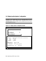
Compaq AlphaServer DS20 system. It covers operation, firmware,
initial troubleshooting, and component installation.
Compaq Computer Corporation
Notice
The information in this publication is subject to change without notice.
COMPAQ COMPUTER CORPORATION SHALL NOT BE LIABLE FOR TECHNICAL
OR EDITORIAL ERRORS OR OMISSIONS CONTAINED HEREIN, NOR FOR
INCIDENTAL OR CONSEQUENTIAL DAMAGES RESULTING FROM THE
FURNISHING, PERFORMANCE, OR USE OF THIS MATERIAL.
This publication contains information protected by copyright. No part of this publication may
be photocopied or reproduced in any form without prior written consent from Compaq
Computer Corporation.
The software described in this document is furnished under a license agreement or
nondisclosure agreement and may be used or copied only in accordance with the terms of the
agreement.
© 1998 Compaq Computer Corporation.
All rights reserved. Printed in the U.S.A.
COMPAQ and the Compaq logo are trademarks or registered trademarks of Compaq
Computer Corporation. AlphaServer, DIGITAL, OpenVMS, and StorageWorks are
trademarks or registered trademarks of Digital Equipment Corporation. Microsoft, Windows,
and Windows NT are registered trademarks of Microsoft Corporation. UNIX is a registered
trademark in the U.S. and other countries, licensed exclusively through X/Open Company Ltd.
Other product names mentioned herein may be trademarks and/or registered trademarks of
their respective companies.
Digital Equipment Corporation now owned by Compaq Computer Corporation.
FCC Notice: The equipment described in this manual generates, uses, and may emit radio
frequency energy. The equipment has been type tested and found to comply with the limits for
a Class A digital device pursuant to Part 15 of FCC Rules, which are designed to provide
reasonable protection against such radio frequency interference. Operation of this equipment
in a residential area may cause interference, in which case the user at his own expense will be
required to take whatever measures are required to correct the interference.
Shielded Cables: If shielded cables have been supplied or specified, they must be used on the
system in order to maintain international regulatory compliance.
Warning! This is a Class A product. In a domestic environment this product may cause radio
interference, in which case the user may be required to take adequate measures.
Achtung! Dieses ist ein Gerät der Funkstörgrenzwertklasse A. In Wohnbereichen können bei
Betrieb dieses Gerätes Rundfunkstörungen auftreten, in welchen Fällen der Benutzer für
entsprechende Gegenmaßnahmen verantwortlich ist.
Avertissement! Cet appareil est un appareil de Classe A. Dans un environnement résidentiel,
cet appareil peut provoquer des brouillages radioélectriques. Dans ce cas, il peut être demandé
à l'utilisateur de prendre les mesures appropriées.
Contents
Preface ............................................................................................................... xi
Chapter 1
1.1
1.2
1.3
1.4
1.5
1.6
System Architecture................................................................................. 1-2
System Features ....................................................................................... 1-4
Front Panel Controls and Indicators ......................................................... 1-6
Rear Panel Ports and Slots ....................................................................... 1-8
Console Terminal................................................................................... 1-10
Options .................................................................................................. 1-12
Chapter 2
2.1
2.2
2.3
2.4
2.5
2.6
2.7
2.8
2.9
Installing the System
System Setup Overview ........................................................................... 2-1
Selecting a Location ................................................................................ 2-1
Environmental Requirements ................................................................... 2-2
Power Requirements ................................................................................ 2-3
Acoustical Data........................................................................................ 2-4
System Accessories.................................................................................. 2-5
Connecting the System............................................................................. 2-6
Connecting to Network Hardware ............................................................ 2-7
Locking the System ................................................................................. 2-8
Chapter 3
3.1
3.2
3.3
3.4
3.5
3.6
3.7
3.8
3.9
3.9.1
3.9.2
3.10
3.10.1
Overview
Operation
Powering Up the System .......................................................................... 3-2
Power-Up Display.................................................................................... 3-4
Booting DIGITAL UNIX ......................................................................... 3-6
Installing DIGITAL UNIX..................................................................... 3-10
Booting OpenVMS ................................................................................ 3-12
Installing OpenVMS .............................................................................. 3-18
Booting Windows NT ............................................................................ 3-20
Installing Windows NT .......................................................................... 3-22
Switching Between Operating Systems .................................................. 3-24
Switching from DIGITAL UNIX or OpenVMS to Windows NT ..... 3-24
Switching from Windows NT to DIGITAL UNIX or OpenVMS ..... 3-25
Updating Firmware ................................................................................ 3-26
Updating Firmware from the CD-ROM........................................... 3-28
iii
3.10.2
3.10.3
3.10.4
3.10.5
3.11
3.11.1
3.11.2
3.11.3
3.12
3.13
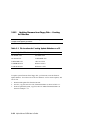
Updating Firmware from Floppy Disk — Creating the Diskettes..... 3-32
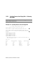
Updating Firmware from Floppy Disk — Performing the Update.... 3-34
Updating Firmware from a Network Device.................................... 3-38
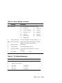
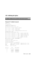
LFU Commands.............................................................................. 3-42
Hard Disk Partitioning ........................................................................... 3-45
Hard Disk Error Conditions............................................................. 3-45
System Partitions ............................................................................ 3-46
How AlphaBIOS Works with System Partitions .............................. 3-47
Using the Halt Button ............................................................................ 3-48
Halt Assertion ........................................................................................ 3-49
Chapter 4
4.1
4.2
4.3
4.4
4.5
4.6
4.6.1
4.6.2
4.6.3
4.7
4.8
4.9
4.10
4.11
4.12
4.13
4.14
4.15
4.16
4.17
4.18
Invoking the SRM Console ...................................................................... 4-2
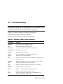
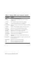
Command Summary ................................................................................ 4-3
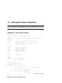
Displaying the System Configuration....................................................... 4-8
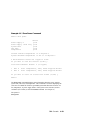
Creating a Power-Up Script ................................................................... 4-15
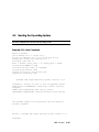
Booting the Operating System................................................................ 4-17
Configuring the System.......................................................................... 4-19
Configuring DSSI............................................................................ 4-19
Configuring a PCI NVRAM Module ............................................... 4-21
Configuring the ISA Bus ................................................................. 4-22
Testing the System................................................................................. 4-24
Making the System Secure ..................................................................... 4-26
Stopping and Starting CPUs................................................................... 4-31
Updating Firmware ................................................................................ 4-33
Forcing a System Crash Dump............................................................... 4-35
Using Environment Variables ................................................................ 4-36
Depositing and Examining Data............................................................. 4-39
Reading a File........................................................................................ 4-42
Initializing the System ........................................................................... 4-43
Finding Help.......................................................................................... 4-45
Switching from SRM to AlphaBIOS Console......................................... 4-46
Environment Variable Summary ............................................................ 4-47
Chapter 5
5.1
5.2
5.3
5.3.1
5.3.2
5.3.3
5.3.4
iv
SRM Console
AlphaBIOS Console
Starting AlphaBIOS ................................................................................. 5-2
Keyboard Conventions and Help.............................................................. 5-4
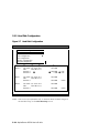
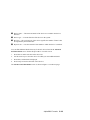
Displaying the System Configuration....................................................... 5-6
System Board Configuration ............................................................. 5-8
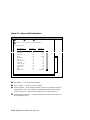
Hard Disk Configuration ................................................................. 5-10
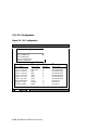
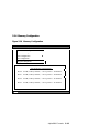
PCI Configuration ........................................................................... 5-12
Memory Configuration.................................................................... 5-15
5.3.5
5.3.6
5.4
5.5
5.5.1
5.5.2
5.6
5.7
5.8
5.8.1
5.8.2
5.9
5.10
5.10.1
5.10.2
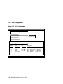
SCSI Configuration......................................................................... 5-16
Integrated Peripherals...................................................................... 5-18
Updating Firmware ................................................................................ 5-20
Setting Up the Hard Disk ....................................................................... 5-22
Creating and Deleting Partitions Manually...................................... 5-24
Formatting a FAT Partition ............................................................. 5-26
Performing Setup Tasks ......................................................................... 5-28
Installing Windows NT .......................................................................... 5-32
Selecting the Version of Windows NT ................................................... 5-34
Designating a Primary Operating System ........................................ 5-36
Primary Operating System and the Auto Start Option...................... 5-38
Switching from AlphaBIOS to SRM Console......................................... 5-42
Running Utility Programs ...................................................................... 5-44
Running Utilities from a Graphics Monitor ..................................... 5-45
Running Utilities from a Serial Terminal ........................................ 5-46
Chapter 6
6.1
6.2
6.2.1
6.2.2
6.3
6.4
6.5
6.6
RCM Overview........................................................................................ 6-2
First-Time Setup ...................................................................................... 6-3
Dialing In and Invoking RCM........................................................... 6-4
Using RCM Locally or with a Modem on COM1 .............................. 6-5
RCM Commands ..................................................................................... 6-6
Using the RCM Switchpack ................................................................... 6-12
Troubleshooting Guide........................................................................... 6-16
Modem Dialog Details ........................................................................... 6-17
Chapter 7
7.1
7.2
7.3
7.4
7.5
Troubleshooting
System Does Not Power Up ..................................................................... 8-2
Appendix A
A.1
A.2
Installing Components
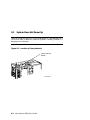
Preparing to Install or Remove Components ............................................ 7-2
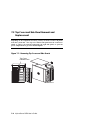
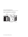
Top Cover and Side Panel Removal and Replacement ............................. 7-4
Installing a CPU Module.......................................................................... 7-8
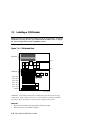
Installing a Memory DIMM Option ....................................................... 7-10
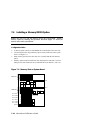
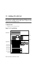
Installing a PCI or ISA Card .................................................................. 7-12
Chapter 8
8.1
Managing the System Remotely
SCSI Bus Configurations
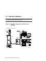
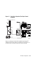
Single-Bus Configurations ...................................................................... A-2
Split-Bus Configuration .......................................................................... A-4
Index
v
Examples
3–1
3–2
3–3
3–4
3–5
3–6
3–7
3–8
3–9
3–10
3–11
3–12
3–13
3–14
3–15
4–1
4–2
4–3
4–4
4–5
4–6
4–7
4–8
4–9
4–10
4–11
4-12
4-13
4-14
4-15
4-16
4-17
4-18
4-19
4-20
4-21
4-22
4–23
4-24
vi
Power-Up Display.................................................................................... 3-4
Booting DIGITAL UNIX from a Local Disk............................................ 3-6
Booting DIGITAL UNIX from a Remote Disk......................................... 3-8
Installing DIGITAL UNIX..................................................................... 3-10
Booting OpenVMS from a Local Disk ................................................... 3-12
Booting OpenVMS from a Disk on a Cluster ......................................... 3-14
Booting OpenVMS from a Remote Disk ................................................ 3-16
Installing OpenVMS .............................................................................. 3-18
Starting LFU from the SRM Console ..................................................... 3-26
Booting LFU from the CD-ROM ........................................................... 3-27
Updating Firmware from the CD-ROM.................................................. 3-28
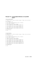
Creating Update Diskettes on an OpenVMS System .............................. 3-33
Updating Firmware from the Internal Floppy Disk................................. 3-34
Selecting AS4X00FW to Update Firmware from the Internal
Floppy Disk ........................................................................................... 3-37
Updating Firmware from a Network Device........................................... 3-38
Show Config Command ........................................................................... 4-8
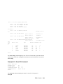
Show CPU Command .............................................................................. 4-9
Show Device Command......................................................................... 4-10
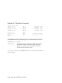
Show Memory Command ...................................................................... 4-12
Show PAL Command ............................................................................ 4-12
Show Power Command.......................................................................... 4-13
Show Version Command........................................................................ 4-14
Editing the nvram Script ........................................................................ 4-15
Clearing the nvram Script ...................................................................... 4-15
Boot Command...................................................................................... 4-17
Set Host Command ................................................................................ 4-19
Prcache Command ................................................................................. 4-21
Isacfg Command.................................................................................... 4-22
Test Command....................................................................................... 4-24
Set Password Command......................................................................... 4-26
Set Secure Command............................................................................. 4-27
Login Command .................................................................................... 4-28
Clear Password Command ..................................................................... 4-30
Halt, and Continue Commands............................................................... 4-31
Lfu Command........................................................................................ 4-33
Crash Command .................................................................................... 4-35
Set envar and Show envar Commands ................................................... 4-36
Creating a User-Defined Environment Variable ..................................... 4-38
Deposit Command ................................................................................. 4-39
4-25
4-26
4-27
4-28
4-29
6–1
6–2
Examine Command................................................................................ 4-39
More Command ..................................................................................... 4-42
Initialize Command ............................................................................... 4-43
Help Command...................................................................................... 4-45
Switching to the AlphaBIOS Console .................................................... 4-46
Sample Remote Dial-In Dialog ................................................................ 6-4
Invoking and Leaving RCM Locally ........................................................ 6-5
Figures
1–1
1–2
1–3
1–4
2–1
2–2
2–3
2–4
2–5
2–6
3–1
3–2
3–3
3–4
3–5
5–1
5–2
5–3
5–4
5–5
5–6
5–7
5–8
5–9
5–10
5–11
5–12
5–13
5–14
5–15
5–16
5–17
5–18
System Architecture................................................................................. 1-2
Front Panel Controls and Indicators ......................................................... 1-6
Rear Panel Ports and Slots ....................................................................... 1-8
Storage Option Compartments ............................................................... 1-12
System Dimensions and Service Area ...................................................... 2-2
Power Supply Requirements .................................................................... 2-3
System Accessories.................................................................................. 2-5
System Connections................................................................................. 2-6
Network Connections............................................................................... 2-7
System Lock and Key .............................................................................. 2-8
Location of On/Off Switch....................................................................... 3-2
AlphaBIOS Boot Screen ........................................................................ 3-20
Installing Windows NT .......................................................................... 3-22
Starting LFU from the AlphaBIOS Console ........................................... 3-26
System Partition Not Defined................................................................. 3-47
Boot Screen ............................................................................................. 5-2
AlphaBIOS Setup Screen ......................................................................... 5-3
Typical First-Level Help Screen .............................................................. 5-4
Second-Level Help Screen ....................................................................... 5-5
Display System Configuration Screen ...................................................... 5-6
System Board Configuration .................................................................... 5-8
Hard Disk Configuration........................................................................ 5-10
PCI Configuration.................................................................................. 5-12
Advanced PCI Information .................................................................... 5-14
Memory Configuration........................................................................... 5-15
SCSI Configuration................................................................................ 5-16
Integrated Peripherals ............................................................................ 5-18
Updating Firmware ................................................................................ 5-20
Hard Disk Setup Screen ......................................................................... 5-22
Create New Partition Dialog Box ........................................................... 5-24
Delete Partition Dialog Box ................................................................... 5-25
Formatting a FAT Partition .................................................................... 5-26
Standard Formatting............................................................................... 5-27
vii
5–19
5–20
5–21
5–22
5–23
5–24
5–25
5–26
5–27
6-1
6-2
6-3
7–1
7–2
7–3
7–4
7–5
7–6
7–7
7–9
7–10
8–1
A–1
A–2
A–3
viii
Standard CMOS Setup Screen................................................................ 5-28
Advanced CMOS Setup Screen.............................................................. 5-30
Installing Windows NT .......................................................................... 5-32
Operating System Selections.................................................................. 5-34
Primary Operating System ..................................................................... 5-36
Operating System Selection Setup.......................................................... 5-38
Switching to the SRM Console .............................................................. 5-42
Run Maintenance Program Dialog Box .................................................. 5-44
AlphaBIOS Utilities Menu ..................................................................... 5-45
RCM Connections.................................................................................... 6-3
Location of RCM Switchpack on Server Control Module....................... 6-12
RCM Switches (Factory Settings) .......................................................... 6-13
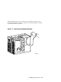
Attaching the Antistatic Wrist Strap......................................................... 7-3
Removing Top Cover and Side Panels ..................................................... 7-4
Replacing Top Cover and Side Panels...................................................... 7-6
CPU Module Slots ................................................................................... 7-8
CPU Module Installation.......................................................................... 7-9
Memory Slots on System Board ............................................................. 7-10
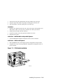
Memory Card Installation ...................................................................... 7-11
PCI and ISA Slots .................................................................................. 7-12
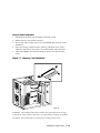
PCI/ISA Card Installation ...................................................................... 7-13
Location of Cover Interlock ..................................................................... 8-2
Single-Bus Configuration (One Multi-Channel Controller) ..................... A-2
Single-Bus Configuration (Two Single-Channel Controllers) .................. A-3
Split-Bus Configuration .......................................................................... A-4
Tables
1
1–1
1–2
1–3
2-1
2-2
2-3
3–1
3–2
4–1
4–2
4–3
4–4
4–5
4–6
4–7
5-1
6-1
6-2
6-3
AlphaServer DS 20 Documentation........................................................... xii
Front Panel Controls and Indicators ......................................................... 1-7
Rear Panel Ports and Slots ....................................................................... 1-9
Comparison of Console Terminals ......................................................... 1-10
Environmental Requirements ................................................................... 2-2
Acoustics - Declared Values per ISO 9296 and ISO 7779 ........................ 2-4
Schallemissionswerte - Werteangaben nach ISO 9296 und ISO 7779/DIN
EN27779.................................................................................................. 2-4
File Locations for Creating Update Diskettes on a PC............................ 3-32
LFU Command Summary ...................................................................... 3-42
Summary of SRM Console Commands .................................................... 4-3
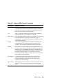
Syntax for SRM Console Commands ....................................................... 4-5
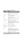
Special Characters for SRM Console ....................................................... 4-6
Device Naming Convention ................................................................... 4-11
PCI address assignments ........................................................................ 4-11
Environment Variable Summary ............................................................ 4-47
Settings for boot_osflags Bootflags (OpenVMS) .................................... 4-51
AlphaBIOS Option Key Mapping .......................................................... 5-46
RCM Command Summary....................................................................... 6-6
RCM Status Command Fields ................................................................ 6-11
RCM Troubleshooting ........................................................................... 6-16
ix
Preface
Intended Audience
This manual is for anyone who manages, operates, or services an AlphaServer DS20
system.
Document Structure
This manual uses a structured documentation design. Topics are organized into small
sections for efficient online and printed reference. Each topic begins with an
abstract. You can quickly gain a comprehensive overview by reading only the
abstracts. Next is an illustration or example, which also provides quick reference.
Last in the structure are descriptive text and syntax definitions.
This manual has eight chapters and one appendix as follows:
•
Chapter 1, Overview, describes the system components.
•
Chapter 2, Installing the System, provides environmental and power
requirements, and set-up instructions.
•
Chapter 3, Operation, gives instructions for powering up the system, booting
the operating system, and updating firmware.
•
Chapter 4, SRM Console, describes commands in the SRM console, for
DIGITAL UNIX and OpenVMS systems.
•
Chapter 5, AlphaBIOS Console, describes menu selections in the AlphaBIOS
console, for Windows NT systems.
•
Chapter 6, Managing the System Remotely, provides information on the
Remote Console Manager (RCM).
•
Chapter 7, Installing Components, gives instructions for adding CPU,
memory, PCI, and ISA cards to the system.
•
Chapter 8, Troubleshooting, provides basic troubleshooting information.
•
Appendix A, SCSI Bus Configurations, provides information on single-bus and
split-bus SCSI configurations.
xi
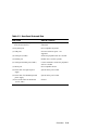
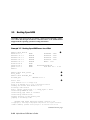
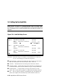
Documentation Titles
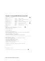
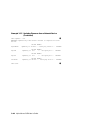
Table 1 lists the books in the AlphaServer DS20 documentation set.
Table 1 AlphaServer DS20 Documentation
Title
Order Number
User and Installation Documentation Kit
QZ–014AA–GZ
User’s Guide
EK–AS140–UG
Basic Installation
EK–AS140–IN
Service Information
Service Manual
xii
EK–AS140–SV
Chapter 1
Overview
This chapter provides an overview of the AlphaServer DS20 system features and
capabilities. The following topics are covered:
•
System Architecture
•
System Features
•
Front Panel Controls and Indicators
•
Rear Panel Ports and Slots
•
Console Terminal
•
System Options
Overview
1-1
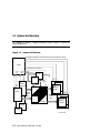
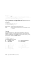
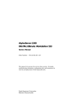
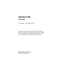
1.1 System Architecture
The AlphaServer DS20 is a high-performance system. Figure 1–1 shows the
system architecture.
Figure 1–1 System Architecture
Command, Address, and Control lines for each Memory Array
C chip
Control lines for D chips
Probe/
Addr.
Probe/
Addr.
CAPbus
P chip
64 bit PCI
P chip
64 bit PCI
CMD/
Addr.
PAD
Bus
CPU 1
(optional)
Up to 2
Memory
Banks
CMD/
Addr.
CPU 0
CPU
Data
Bus
Memory
Data
Bus
8 D chips
1 or 2
Memory
Banks
B cache
B cache
PKW1400-98
1-2
AlphaServer DS20 User’s Guide
The AlphaServer DS20 is a switch-based interconnect system using a cross-bar
switch chipset that allows data to move directly from place to place in the system.
Figure 1–1 is a block diagram showing the various data paths through the switch.
The pedestal enclosure contains the system and allows for up to ten internal storage
devices: one dedicated diskette drive slot, two removable media slots, and seven 3.5inch hard disk drives. All CPUs, memory and I/O components are on a single board
that contains the memory subsystem, two PCI buses, the ISA bus, the integrated I/O
controllers. The remote console manager (RCM) is on a separate server feature
module.
The control panel includes Halt, Reset, and On/Off buttons.
Supported Operating Systems
This system supports the following minimum revisions of these operating systems:
•
Microsoft Windows NT
4.0 with service pack 3 or later
•
OpenVMS
7.1-2
•
DIGITAL UNIX
4.0E
The system runs in two modes. In program mode, the operating system controls the
system and manages the execution of application programs. In console mode, the
console program controls the system allowing control of system management
functions.
System Console Firmware
You perform many of the tasks for managing and configuring your server system in
console mode, where the system is controlled by the console subsystem, rather than
the operating system.
The console subsystem, located in ROM (read-only memory) on the system board,
contains the firmware that interacts directly with hardware components and
facilitates interaction between the hardware and the operating system.
Overview
1-3
1.2 System Features
The system provides a number of features that enhance its reliability and
improve its expansion capabilities, as well as facilitate hardware management
and improve security.
Reliability
• 64-bit Alpha architecture
Provides significantly better performance than
32-bit architecture.
• Error correction code (ECC)
on memory and CPU cache
Allows recovery from most cache and memory
errors.
• Variable fan speed
Adjusts fan speed according to system
temperature.
• Integral Remote Console
Management (RCM) function
Enables remote access to system.
• Internal sensors
Monitor and detect internal system temperature,
fan failure, power supply temperature.
• Hot swap disk capability
Allows replacement of StorageWorks disk drives
while the system continues to operate.
• Redundant power
A single power supply can run a fully configured
system. An optional second power supply can be
added to provide sufficient power for the system
to continue to run even if one supply should fail.
System Expansion
• Flexible memory
architecture.
System memory can be expanded from 128 MB to
4 GB.
• Six PCI expansion slots.
One PCI slot can be used as
an ISA slot instead.
Accommodates industry-standard option cards
such as Ethernet, FDDI, and SCSI devices.
• Dual-ported integrated
UltraSCSI controller
Supports tape, disks, and CD-ROM without use of
an expansion slot.
1-4
AlphaServer DS20 User’s Guide
• Capacity for 10 internal
storage devices
Accommodates one StorageWorks modular
storage system, which supports up to seven 3½inch UltraSCSI drives. Also supports up to two
5½-inch, half-height drives (CD-ROM or tape),
and one 3½-inch diskette.
• External ports
Two serial ports and one parallel port support
external options such as a printer, modem, or
local terminal.
• UltraSCSI storage drive
Supports up to 7 high-performance drive
technology.
System Management
• System diagnostics
Allow local and remote diagnosis of system
problems.
• Hardware configuration
Allows local and remote system configuration.
• Unique asset management
Unique system identifier in nonvolatile memory
provides easy asset management.
• RAM-based error log
Records startup error messages.
• Firmware upgrade utility
Provides loading and verification of firmware
versions.
• Environmental failure events
logged in NVRAM
Provides troubleshooting information for system
shutdowns.
• Hard drive indicator lights
Provide immediate status information on hard
drive activity or fault indication.
System Security
• Key lock
Limits access to system components.
• Security loop (on rear of
system unit)
Allows system to be secured in place.
• Interlock sensor switch
Automatically turns off system power if the top
cover is removed while power is on.
Overview
1-5
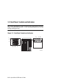
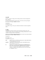
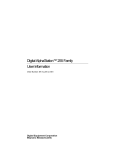
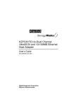
1.3 Front Panel Controls and Indicators
The controls and indicators on the front panel of the system unit are shown in
Figure 1-2 and described in Table 1-1. The control panel display shows start-up
messages during power-up.
Figure 1–2 Front Panel Controls and Indicators
8
9 10
7
6
5
4
3 2
1
IP00190
1-6
AlphaServer DS20 User’s Guide
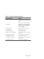
Table 1-1 Front Panel Controls and Indicators
Control or Indicator
Function
(1) Halt button
Halts an OpenVMS or DIGITAL UNIX
system, returning it to console mode
control.
Does not affect a Windows NT system.
(2) Reset button
Reinitializes the system and performs
startup tests. Can be used with the Halt
button to bring up the SRM console
while in AlphaBIOS.
(3) On/Off indicator
Lights when the system is turned on.
(4) On/Off button
Turns system on and off.
(5) Control panel display
Displays startup messages.
(6) Diskette drive activity indicator
Lights when the system is accessing the
diskette drive.
(7) Diskette drive eject button
Ejects a diskette from the diskette drive.
(8) CD-ROM volume control
Adjusts headphone volume.
(9) CD-ROM activity indicator
Lights when the system is accessing the
CD-ROM drive.
(10) CD-ROM eject button
Ejects disk from CD-ROM drive.
Overview
1-7
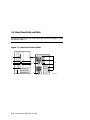
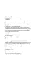
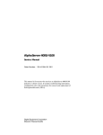
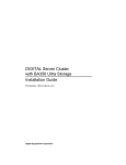
1.4 Rear Panel Ports and Slots
The ports and slots on the rear of the system unit are shown in Figure 1–3 and
described in Table 1-2.
Figure 1–3 Rear Panel Ports and Slots
5
4
6
3
2
3
7
9
10
1
8
IP00210A
1-8
AlphaServer DS20 User’s Guide
Table 1-2 Rear Panel Ports and Slots
Port or Slot
Used to connect...
(1) Up to six PCI slots, or up to five PCI
slots and one ISA slot
Option cards for network, video, or disk
controllers
(2) Keyboard port
PS/2-compatible keyboard
(3) USB ports
Universal serial bus ports – not
supported
(4) Serial port (COM2)
Serial-line peripheral such as a modem
(5) Parallel port
Parallel device such as a printer
(6) Serial port/terminal port (COM1)
Console terminal or serial-line peripheral
such as a modem
(7) Mouse port
PS/2-compatible mouse
(8) Power inlet for required power
supply
System unit to power outlet
(9) Power inlet for redundant optional
power supply
System unit to power outlet
(10) Five SCSI connector knockouts
(16-bit, wide)
Unused
Overview
1-9
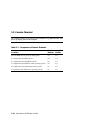
1.5 Console Terminal
The console terminal can be either a serial terminal or a graphics monitor. The
power-up display prints to this terminal.
Table 1-3 Comparison of Console Terminals
Condition
Serial
Terminal
Graphics
Monitor
Does the SRM console power-up display print?
Yes
Yes
Is it supported by the SRM console?
Yes
Yes
Is it supported by the AlphaBIOS console?
Yes
Yes
Is it supported by the DIGITAL UNIX operating system?
Yes
Yes
Is it supported by the OpenVMS operating system?
Yes
Yes
Is it required by the Windows NT operating system?
No
Yes
1-10
AlphaServer DS20 User’s Guide
The console terminal can be a serial (character cell) terminal connected to the COM1
port or a graphics monitor connected to a VGA adapter on PCI 0. If the console
terminal is connected to COM1, the entire power-up display prints. (See Section 3.2
for information about the power-up display.)
The console environment variable is set to serial when the console terminal is a
serial terminal; it is set to graphics when the console terminal is a graphics monitor.
(See Section 4.18 for information about environment variables.)
If the console environment variable is set to serial, os_type is set to unix or
openvms, and no terminal is attached to COM1, pressing a carriage return on a
graphics terminal attached to the keyboard port (after power-up testing has
completed) makes it the console device and the console prompt is sent to it.
If the console environment variable is set to graphics and no graphic adapter or
keyboard is present, pressing a carriage return on a serial terminal attached to COM1
(after power-up testing has completed) makes it the console device and the console
prompt is displayed.
NOTE: The console prompt displays only after the entire power-up sequence is
complete. This can take up to several minutes if the memory is very large.
Overview
1-11
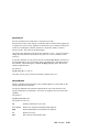
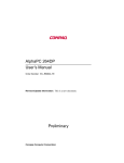
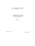
1.6 Options
Options include storage, PCI and ISA I/O cards, redundant power, and
additional memory cards. Figure 1–4 shows storage option compartments.
Figure 1–4 Storage Option Compartments
CD-ROM Drive
Compartment
Diskette Drive
Compartment
StorageWorks
Drives Shelf
IP00195
Storage Options
Storage options are located in several compartments inside the system as shown in
Figure 1-4. The system accommodates the following types of storage options:
•
One diskette drive
•
One CD-ROM drive
•
Up to seven 3½-inch StorageWorks drives or two 5½-inch drives
1-12
AlphaServer DS20 User’s Guide
PCI and ISA Options
The system supports PCI options and ISA options for:
•
SCSI storage expansion
•
Networking and communications
•
Graphics
•
Sound
Memory Options
You can increase your system’s memory to 4 gigabytes. More memory allows your
system to run memory-intensive software more quickly.
The system supports the following memory option sizes: 128 MB, 256 MB, 512 MB,
and 1 GB. Each option is made up of four 200-pin DIMM modules.
Ordering Options
The list of supported options is subject to change. Contact your sales representative
for information on the current list of supported options and for information on
ordering. If you are an Internet participant, you can obtain information related to the
Compaq AlphaServer DS20 system through the DIGITAL FTP archive:
ftp.digital.com: /pub/DEC/Alpha/systems/asds20/docs/
For access through the DIGITAL worldwide web server:
http://www.service.digital.com/alpha/server/ds20.html
Users of the Windows NT operating system can access the Microsoft hardware
compatibility list (HCL) for a list of officially supported devices:
http://www.windowsnt.digital.com/support/hcl/hcl.htm
Overview
1-13
Chapter 2
Installing the System
This chapter explains how to set up and install your system hardware. The following
topics are discussed:
•
System Setup Overview
•
Selecting a Location
•
Environmental Requirements
•
Power Requirements
•
Acoustical Data
•
System Accessories
•
Connecting the System
•
Connecting to Network Hardware
•
Locking the System
2.1 System Setup Overview
The following list summarizes the steps for setting up your system. The steps may
vary depending on the options in your system.
1.
Select a location for the system, giving consideration to service access,
environmental requirements, and power requirements.
2.
Confirm that you have all the desired accessories that ship with the system and
any accessories you may want to add.
3.
Connect the keyboard, mouse, printer, and monitor or terminal.
4.
Connect to the network hardware.
5.
Verify your hardware setup.
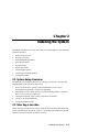
2.2 Selecting a Location
When choosing a system location, keep in mind the environmental requirements and
power requirements for the system. Figure 2–1 shows the system dimensions and the
clearance needed to access the system for servicing.
Installing the System
2-1
Figure 2–1 System Dimensions and Service Area
35 cm
(14.1 in)
53 cm
(21 in)
44 cm
(17.4 in)
1M
(36 in)
65 cm
(26 in)
IP00208
2.3 Environmental Requirements
Table 2-1 Environmental Requirements
Condition
Specification
Temperature range
Room temperature: Between 10º C and 40º C (50º F
and 104º F).
Relative humidity
Between 10% and 90% (20% to 80% with
removable media options).
Air circulation
Allow a minimum clearance of 8 cm (3 inches) on
all sides of the system unit to allow sufficient air
circulation. Fans inside the system unit circulate the
air to prevent excessive heat, which can damage the
system components.
2-2
AlphaServer DS20 User’s Guide
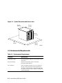
2.4 Power Requirements
Your system ships with a single power supply unless the customer chose a second
optional power supply for redundancy. Power supplies connect to an AC outlet.
Figure 2–2 Power Supply Requirements
Optional redundant power
Power Supply
Cable Socket
100-120 VAC 7.3A 50-60 Hz
220-240 VAC 4.0A 50-60 Hz
100-120 VAC 7.3A 50-60 Hz
220-240 VAC 4.0A 50-60 Hz
Power
Supply
Cable
= Properly Grounded Power Receptacle
PK1468-98
NOTE: Current ratings are maximum with a fully loaded system.
Installing the System
2-3
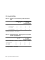
2.5 Acoustical Data
Table 2-2 Acoustics - Declared Values per ISO 9296 and ISO
7779
Sound Power Level
LWAd B
AlphaServer DS 20 Systems
Sound Pressure Level
LpAm dBA
(bystander positions)
Idle
Operate
Idle
Operate
without hard drives
5.7
5.7
38
38
with 1 x RZ1CB
5.7
5.7
38
39
with 7 x RZ1CB disks
5.8
6.0
40
42
[Current values for specific configurations are available from Compaq Computer
Corporation representatives. 1 B = 10 dBA.]
Table 2-3 Schallemissionswerte - Werteangaben nach ISO 9296
und ISO 7779/DIN EN27779
Schalleistungspegel
LWAd B
AlphaServer DS20 Systeme
Schalldruckpegel
LpAm dBA
(Zuschauerpositionen)
Leerlauf
Betrieb
Leerlauf
Betrieb
Ohne Plattenlaufwerke
5,7
5,7
38
38
Mit 1 x RZ1CB
5,7
5,8
38
39
Mit 7 x RZ1CB
5,8
6,0
40
42
[Aktuelle Werte für spezielle Ausrüstungsstufen sind über die Compaq Computer
Vertretungen erhältlich. 1 B = 10 dBA.]
2-4
AlphaServer DS20 User’s Guide
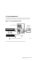
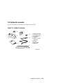
2.6 System Accessories
Figure 2-3 shows the accessories that are included with the system.
Figure 2–3 System Accessories
1
2
3
4
5
System keys (2)
Installation card
User’s Guide
Floppies
H8571-J serial
connector
6 Mouse
7 Power cord
8 Keyboard
PK1484-98
Installing the System
2-5
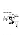
2.7 Connecting the System
Connect the system components as shown in Figure 2–4.
Figure 2–4 System Connections
VTxxx
VGA
1
2
ML014165A
2-6
AlphaServer DS20 User’s Guide
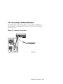
2.8 Connecting to Network Hardware
The system supports various network options. You can connect to ThinWire, as
shown in Figure 2-5. With appropriate options, you can also connect to FDDI and
token ring networks.
Figure 2–5 Network Connections
UTP 10/100 Mbps
PK1469-98
Installing the System
2-7
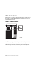
2.9 Locking the System
Pedestal systems are protected by a key lock located on the front. Turning the key to
the left locks the front door. When the front door is locked, the top cover and side
panel latch cannot be accessed.
Figure 2–6 System Lock and Key
IP00192
Turning the key to the right unlocks the system unit and allows you access to install
or remove system components. When the system unit is unlocked, push the lock to
open the door. Figure 2–6 shows the system lock in the unlocked position.
Additional security is provided by a latching loop on the rear panel of the system
unit that allows you to attach the system unit to a post or other fixed object.
2-8
AlphaServer DS20 User’s Guide
Chapter 3
Operation
This chapter provides basic operating instructions, including powering up the system,
booting, and operating system installation. Note that your choice of operating system
has already been installed at the factory; this information is provided so that should
you decide to change operating systems, you may. It also provides information
about updating firmware.
Sections in this chapter are:
•
Powering Up the System
•
Power-Up Display
•
Booting DIGITAL UNIX
•
Installing DIGITAL UNIX
•
Booting OpenVMS
•
Installing OpenVMS
•
Booting Windows NT
•
Installing Windows NT
•
Switching Between Operating Systems
•
Updating Firmware
•
Hard Disk Partitioning
•
Using the Halt Button
•
Halt Assertion
Operation
3-1
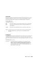
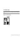
3.1
Powering Up the System
To power up the system, press the On/Off button to the On position.
Figure 3–1 Location of On/Off Button
On/Off Button in
("On" Position)
On/Off Button Out
("Off" Position)
IP00193
3-2
AlphaServer DS20 User’s Guide
Power up the system by pressing in the On/Off button (see Figure 3–1). Testing
begins, and screen text similar to that in Example 3-1 displays (if the console
terminal is a serial terminal connected to the COM1 port), along with status
messages in the control panel display. If the console terminal is a graphics monitor,
only the last few lines of the power-up display print. See Section 3.2 for more
information.
Operation
3-3
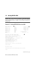
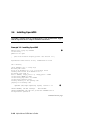
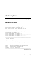
3.2
Power-Up Display
The entire power-up display prints to a serial terminal (if the console
environment variable is set to serial); the last several lines print to either a serial
terminal or a graphics monitor. Power-up status also displays on the control
panel display.
Example 3–1 Power-Up Display
512 Meg of system memory
➊
probing hose 1, PCI
➋
bus 0, slot 7 -- pka -- QLogic ISP1020
bus 0, slot 8 -- ewa -- DECchip 21140-AA
probing hose 0, PCI
probing PCI-to-ISA bridge, bus 1
bus 0, slot 5, function 1 -- dqa -- Cypress
bus 0, slot 5, function 2 -- dqb -- Cypress
bus 0, slot 6, function 0 -- pkb -- Adaptec
bus 0, slot 6, function 1 -- pkc -- Adaptec
bus 0, slot 7 -- vga -- DEC PowerStorm
bus 0, slot 8 -- ewa -- DECchip 21040-AA
Testing the System
Testing the Disks (read only)
Testing the Network
System Temperature is 22 degrees C
82C693 IDE
82C693 IDE
AIC-7895
AIC-7895
Compaq AlphaServer DS20 Console V5.4-x, Aug 26 1998 16:07:57
P00>>>
3-4
AlphaServer DS20 User’s Guide
➌
➊
➋
Memory size is determined.
➌
The SRM console banner and prompt are printed. (The SRM prompt is shown
in this manual as P00>>>. It can, however, be P01>>>. The number indicates
the primary processor.) If the auto_action environment variable is set to boot
or restart and the os_type environment variable is set to unix or openvms, the
DIGITAL UNIX or OpenVMS operating system boots.
The PCI bridges and attendant buses (indicated as IODn by the console) are
probed and the devices are reported. I/O adapters are configured.
If the system is running the Windows NT operating system (the os_type
environment variable is set to nt), the SRM console loads and starts the
AlphaBIOS console.
Refer to Chapter 4 for information about the SRM console and to Chapter 5 for
AlphaBIOS.
Operation
3-5
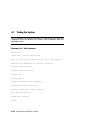
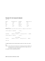
3.3
Booting DIGITAL UNIX
®
DIGITAL UNIX can be booted from a local disk or a remote disk through an
Ethernet connection. Refer to the documentation shipped with the operating
system for booting instructions. Example 3–2 shows booting a local disk from a
desktop system.
Example 3–2 Booting DIGITAL UNIX from a Local Disk
P00>>> show device
dkc0.0.0.9.0
dkc100.1.0.9.0
dkc200.2.0.9.0
dkc300.3.0.9.0
dkc500.5.0.9.0
dva0.0.0.0.0
ewa0.0.0.8.1
pkc0.7.0.9.0
P00>>>
➊
DKC0
DKC100
DKC200
DKC300
DKC500
DVA0
EWA0
PKC0
RZ1DB-BA
RZ1CB-CA
RZ1CB-CA
RZ1CB-CA
RRD47
LYG0
LYJ0
LYJ0
LYJ0
1337
00-00-F8-00-0E-3B
SCSI Bus ID 7
5.54
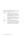
P00>>> boot -file vmunix -flags a dkc0
(boot dkc0.0.0.9.0 -file vmunix -flags a)
block 0 of dkc0.0.0.9.0 is a valid boot block
reading 16 blocks from dkc0.0.0.9.0
bootstrap code read in
base = 1ee000, image_start = 0, image_bytes = 2000
initializing HWRPB at 2000
initializing page table at 1fff0000
initializing machine state
setting affinity to the primary CPU
jumping to bootstrap code
➋
➌
DIGITAL UNIX boot - Fri Aug 7 20:30:19 EDT 1998
Loading vmunix ...
.
.
The system is ready.
DIGITAL UNIX Version V4.0E (sabl28.eng.pko.dec.com) console
login:
Continued on next page
3-6
AlphaServer DS20 User’s Guide
Example 3–2 Booting DIGITAL UNIX from a Local Disk
(Continued)
************************************************************************
*
* Starting Desktop Login on display :0...
*
* Wait for the Desktop Login screen before logging in.
*
************************************************************************
DIGITAL UNIX Version V4.0E (sabl28.eng.pko.dec.com) console
➍
login:
➊
The show device command displays device information, including name and
type of connection to the system. See Section 4.3 for a description of the show
device command and the device naming convention.
➋
The operating system is on the third disk connected to the system through the
controller in slot 3 of PCI1. The name of this device, dkc0, is used as an
argument to the boot command.
➌
This command loads DIGITAL UNIX from the disk dkc0, using the boot file
vmunix and autobooting to multiuser mode. See Section 4.5 for a description
of the boot command.
The boot command accepts the name of a boot device, a boot file name
through the -file option, and boot flags through the -flags option. The
environment variables bootdef_dev, boot_file, and boot_osflags can also be
used to specify the default boot device or device list, the default boot file, and
flag information. When an option and the corresponding environment variable
are both in a command string, the option overrides the environment variable.
The value of the environment variable, however, is not changed. See Section
4.18 for information about environment variables.
➍
The operating system banner displays.
Operation
3-7
Example 3–3 Booting DIGITAL UNIX from a Remote Disk
P00>>> show device
dka0.0.0.7.1
DKA0
RZ28D 0010
dka100.1.0.7.1
DKA100 SEAGATE ST32155W 0596
dka200.2.0.7.1
DKA200 RZ28D 0010
dka400.4.0.7.1
DKA400 PLEXTOR CD-ROM PX-12TS
dva0.0.0.0.0
DVA0
ewa0.0.0.8.0
EWA0
08-00-2B-E2-9C-60
pka0.7.0.7.1
PKA0
SCSI Bus ID 7 5.54
pkb0.7.0.6.0
PKB0
SCSI Bus ID 7
P00>>
P00>>> boot -flags an -protocols bootp ewa
➌
(boot ewa0.0.0.4.1 -flags an)
Building FRU table
➊
1.02
➋
Trying BOOTP boot.
Broadcasting BOOTP Request...
Received BOOTP Packet File Name: /var/adm/ris/ris0.alpha/hvmunix
local inet address: 16.122.128.26
remote inet address: 16.122.128.59
TFTP Read File Name: /var/adm/ris/ris0.alpha/hvmunix
.....................................................................
.....................................................................
bootstrap code read in
base = 200000, image_start = 0, image_bytes = 9a0fa0
initializing HWRPB at 2000
initializing page table at 1f2000
initializing machine state
setting affinity to the primary CPU
jumping to bootstrap code
Secondary boot program - Thu Aug 1 22:33:13 EST 1996
Loading vmunix ...
.
.
.
The system is ready.
DIGITAL UNIX Version V4.0E (sabl28.eng.pko.dec.com) console
3-8
AlphaServer DS20 User’s Guide
➍
➊
The show device command displays device information, including name and
type of connection to the system. See Section 4.3 for a description of the show
device command and the device naming convention.
➋
The operating system is on a remote disk accessed through the Ethernet
controller in slot 4 of PCI1. The name of this device, ewa0, is used as an
argument to the boot command.
➌
This command loads DIGITAL UNIX from ewa0, autobooting to multiuser
mode. See Section 4.5 for a description of the boot command.
The boot command accepts the name of a boot device, a boot file name
through the -file option, and boot flags through the -flags option. The
environment variables bootdef_dev, boot_file, and boot_osflags can also be
used to specify the default boot device or device list, the default boot file, and
flag information. When an option and the corresponding environment variable
are both in a command string, the option overrides the environment variable.
The value of the environment variable, however, is not changed. See Section
4.18 for information about environment variables.
➍
The operating system banner displays.
Operation
3-9
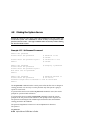
3.4
Installing DIGITAL UNIX
DIGITAL UNIX is installed from the CD-ROM. Refer to the documentation
shipped with the CD-ROM for installation instructions.
Example 3–4 Installing DIGITAL UNIX
P00>>> show device
dka0.0.0.7.1
dka100.1.0.7.1
dka200.2.0.7.1
dka300.3.0.7.1
dka500.5.0.7.1
dva0.0.0.0.0
ewa0.0.0.8.1
pka0.7.0.7.1
P00>>>
DKA0
DKA100
DKA200
DKA300
DKA500
DVA0
EWA0
PKA0
RZ1DB-BA
RZ1CB-CA
RZ1CB-CA
RZ1CB-CA
RRD47
00-00-F8-00-0E-3B
SCSI Bus ID 7
LYG0
LYJ0
LYJ0
LYJ0
1337➊
5.54
➊
P00>>> boot dka500
(boot dka500.5.0.7.1 -flags A)
block 0 of dka500.5.0.7.1 is a valid boot block
reading 16 blocks from dka500.5.0.7.1
bootstrap code read in
base = 1ee000, image_start = 0, image_bytes = 2000
initializing HWRPB at 2000
initializing page table at 1fff0000
initializing machine state
setting affinity to the primary CPU
jumping to bootstrap code
DIGITAL UNIX boot - Thu Jul 16 16:59:31 EDT 1998
Loading vmunix ...
.
.
.
INIT: SINGLE-USER MODE
Initializing system for DIGITAL UNIX installation.
Please wait...
*** Performing CDROM Installation
Loading installation process and scanning system hardware.
The “ Welcome to the DIGITAL UNIX Installation Procedure” appears.
➋
Continued on next page
3-10
AlphaServer DS20 User’s Guide
➊
Use the boot command to install the operating system from the CD-ROM,
which is always dka500.
➋
See your operating system documentation for further installation instructions.
Operation
3-11
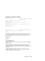
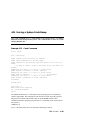
3.5
Booting OpenVMS
OpenVMS can be booted from a local disk, a disk connected through a cluster,
or a remote disk through an Ethernet connection. Refer to the documentation
shipped with the operating system for booting instructions.
Example 3–5 Booting OpenVMS from a Local Disk
P00>>> show device
dka0.0.0.7.1
dka100.1.0.7.1
dka200.2.0.7.1
dka300.3.0.7.1
dka500.5.0.7.1
dva0.0.0.0.0
ewa0.0.0.8.1
pka0.7.0.7.1
P00>>>
➊
DKA0
DKA100
DKA200
DKA300
DKA500
DVA0
EWA0
PKA0
RZ1DB-BA LYG0
RZ1CB-CA LYJ0
RZ1CB-CA LYJ0
RZ1CB-CA LYJ0
RRD47 1337
00-00-F8-00-0E-3B
SCSI Bus ID 7
5.54
P00>>> show boot_reset
boot_reset
ON
P00>>> show bootdef_dev
bootdef_dev
dka200.2.0.7.1
➋
P00>>> boot
(boot dka200.2.0.7.1 -flags 0,0)
block 0 of dka200.2.0.7.1 is a valid boot block
reading 893 blocks from dka200.2.0.7.1
bootstrap code read in
base = 1fa000, image_start = 0, image_bytes = 6fa00
initializing HWRPB at 2000
initializing page table at 1fff0000
initializing machine state
setting affinity to the primary CPU
jumping to bootstrap code
➍
➌
OpenVMS (TM) Alpha Operating System, Version 7.1-2
$!Copyright(c) 1998 Digital Equipment Corporation. All rights reserved.
%STDRV-I-STARTUP, OpenVMS startup begun at 30-JUL-1998 11:47:11.04
Continued on next page
3-12
AlphaServer DS20 User’s Guide
Example 3–5 Booting OpenVMS from a Local Disk (Continued)
.
.
.
The OpenVMS system is now executing the site-specific startup commands.
.
.
.
Welcome to OpenVMS (TM) Alpha Operating System, Version V7.1-2
➎
Username:
➊
The show device command displays device information. See Section 4.3 for a
description of the show device command and the device naming convention.
➋
The boot_reset environment variable was previously set to “on,” causing the
power-up trace to display when the system initializes (see Section 3.2). See
Section 4.18 for commands used with environment variables.
➌
The bootdef_dev environment variable specifies the default boot device. In
this example, the default boot device was previously set to dka200.2.0.7.1.
➍
No boot device is specified in the boot command; the default boot device was
set with the environment variable. See Section 4.5 for a description of the boot
command.
The boot command accepts the name of a boot device, a boot file name
through the -file option, and boot flags through the -flags option. The
environment variables bootdef_dev, boot_file, and boot_osflags can also be
used to specify the default boot device or device list, the default boot file, and
flag information. When an option and the corresponding environment variable
are both in a command string, the option overrides the environment variable.
The value of the environment variable, however, is not changed. See Section
4.18 for information about environment variables.
➎
The operating system banner displays.
Operation
3-13
Example 3–6 Booting OpenVMS from a Disk on a Cluster
P00>>> show bootdef_dev
➊
bootdef_dev
dua110.0.0.8.0
➋
P00>>> show device
dka0.0.0.7.1
DKA0
RZ1CB-CS 0844
dka100.1.0.7.1
DKA100
RZ28 D41C
dka200.2.0.7.1
DKA200
RZ28 441C
dka300.3.0.7.1
DKA300
RZ1EF-AB 0370
dka500.5.0.7.1
DKA500
RRD47 0557
dkb0.0.0.2000.1
DKB0
RZ1DB-BA LYG0
dkb200.2.0.2000.1
DKB200
RZ1DB-BA LYG0
dkb400.4.0.2000.1
DKB400
RZ1CB-BA LYG0
dkc100.1.0.2001.1
DKC100
RZ1DB-BA LYG0
dkc300.3.0.2001.1
DKC300
RZ1DB-BA LYG0
dua101.3.0.8.0
$1$DIA101 (RF0700)
RF35
dua103.1.0.8.0
$1$DIA103 (RF0701)
RF36
dua110.0.0.8.0
$1$DIA110 (DENVER)
RF74 ➌
dua240.2.0.8.0
$1$DIA240 (E1ILMO)
EF52
dva0.0.0.0.0
DVA0
ewa0.0.0.2002.1
EWA0
00-06-2B-00-0A-59
pka0.7.0.7.1
PKA0
SCSI Bus ID 7 5.57
pkb0.7.0.2000.1
PKB0
SCSI Bus ID 7
pkc0.7.0.2001.1
PKC0
SCSI Bus ID 7
pua0.7.0.8.0
PIA0
DSSI Bus ID 7
➍
P00>>> boot
(boot dua110.0.0.8.0 -flags 0)
Building FRU table
.
.
.
Welcome to OpenVMS Alpha (TM) Operating System, Version V7.1-2 ➎
3-14
AlphaServer DS20 User’s Guide
➊
➋
➌
➍
The bootdef_dev environment variable specifies the default boot device.
The show device command displays device information, including name and
type of connection to the system. See Section 4.3 for a description of the show
device command and the device naming convention.
The disk dua110.0.0.8.0 is on the cluster that includes this system.
No boot device is specified in the boot command; the default boot device was
set with the environment variable. See Section 4.5 for a description of the boot
command.
The boot command accepts the name of a boot device, a boot file name
through the -file option, and boot flags through the -flags option. The
environment variables bootdef_dev, boot_file, and boot_osflags can also be
used to specify the default boot device or device list, the default boot file, and
flag information. When an option and the corresponding environment variable
are both in a command string, the option overrides the environment variable.
The value of the environment variable, however, is not changed. See Section
4.18 for information about environment variables.
➎
The operating system banner prints.
Operation
3-15
Example 3–7 Booting OpenVMS from a Remote Disk
P00>>> show device
dka0.0.0.7.1
DKA0
dka100.1.0.7.1
DKA100
dka200.2.0.7.1
DKA200
dka500.5.0.7.1
DKA500
dva0.0.0.0.0
DVA0
ewa0.0.0.8.0
EWA0
pka0.7.0.7.1
PKA0
pkb0.7.0.6.0
PKB0
P00>>
P00>>> boot ewa0 -flags 0
(boot ewa0.0.0.2.0 -flags 0)
Building FRU table
➊
RZ28D 0010
SEAGATE ST32155W 0596
RZ28D 0010
PLEXTOR CD-ROM PX-12TS
08-00-2B-E2-9C-60
SCSI Bus ID 7 5.54
SCSI Bus ID 7
1.02
➊
➋
Trying MOP boot.
.............
Network load complete.
.
.
.
Welcome to OpenVMS Alpha (TM) Operating System, Version V7.1-2 ➌
3-16
AlphaServer DS20 User’s Guide
➊
The show device command displays device information, including name and
type of connection to the system. In this example the Ethernet connection is
ewa0. See Section 4.3 for a description of the show device command and the
device naming convention.
➋
The boot command specifies ewa0 as the boot device. See Section 4.5 for a
description of the boot command.
The boot command accepts the name of a boot device, a boot file name
through the -file option, and boot flags through the -flags option. The
environment variables bootdef_dev, boot_file, and boot_osflags can also be
used to specify the default boot device or device list, the default boot file, and
flag information. When an option and the corresponding environment variable
are both in a command string, the option overrides the environment variable.
The value of the environment variable, however, is not changed. See Section
4.18 for information about environment variables.
➌
The operating system banner prints.
Operation
3-17
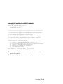
3.6
Installing OpenVMS
OpenVMS is installed from the CD-ROM. Refer to the documentation shipped
with the OpenVMS kit for complete installation instructions.
Example 3–8 Installing OpenVMS
➊
P00>>> boot -flags 0,0 dka500
Initializing...
SROM V3.0 on cpu0
.
. [The initialization display prints. See Section 3.2.]
.
AlphaServer DS20 Console V5.4-x, 2-APR-1998 15:17:48
CPU 0 booting
(boot dka500.5.0.1.1 -flags 0,0)
Building FRU table
block 0 of dka500.5.0.1.1 is a valid boot block
reading 1002 blocks from dka500.5.0.1.1
bootstrap code read in
base = 200000, image_start = 0, image_bytes = 7d400
initializing HWRPB at 2000
initializing page table at 1f2000
initializing machine state
setting affinity to the primary CPU
jumping to bootstrap code
OpenVMS (TM) Alpha Operating System, Version 7.1x
➋
%SMP-I-SECMSG, CPU #01 message: P01>>>START
%SMP-I-CPUBOOTED, CPU #01 has joined the PRIMARY CPU in
multiprocessor operation
Continued on next page
3-18
AlphaServer DS20 User’s Guide
Example 3–8 Installing OpenVMS (Continued)
Installing required known files...
Configuring devices...
****************************************************************
You can install or upgrade the OpenVMS Alpha operating system
or you can install or upgrade layered products that are included
on the OpenVMS Alpha operating system CD-ROM.
You can also execute DCL commands and procedures to perform
"standalone" tasks, such as backing up the system disk.
Please choose one of the following:
1)
2)
3)
4)
5)
Install or upgrade OpenVMS Alpha Version 7.1x
List layered product kits that this procedure can install
Install or upgrade layered product(s)
Execute DCL commands and procedures
Shut down this system
Enter CHOICE or ? to repeat menu: (1/2/3/4/5/?)
➊
Use the boot command to install the operating system from the CD-ROM,
which is always dka500.
➋
See your operating system documentation for installation instructions.
Operation
3-19
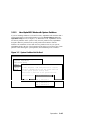
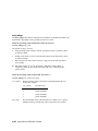
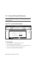
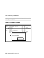
3.7
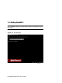
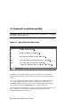
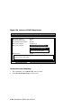
Booting Windows NT
Microsoft Windows NT is started from the AlphaBIOS Boot screen.
Figure 3–2 AlphaBIOS Boot Screen
AlphaBIOS Setup
Display System
AlphaBIOS Upgrade…
Hard Disk Setup…
CMOS Setup…
Network Setup…
Install Windows NT
Utilities
About AlphaBIOS…
8
Press ENTER to install Windows NT.
ESC = Exit
3-20
AlphaServer DS20 User’s Guide
F1= Help
Two SRM environment variables must be set properly for Windows NT to boot. The
setting of the SRM os_type environment variable determines if AlphaBIOS is loaded
and started on reset and power-up. If os_type is set to nt, after the power-up display
the SRM console is loaded and started, and it then loads and starts the AlphaBIOS
console. AlphaBIOS must be running before Windows NT can be booted. Windows
NT requires a graphics monitor as its console. Setting the SRM console environment
variable to graphics and having a graphics monitor attached to your system meets
this requirement. After setting these two variables, you have to power-down and
power-up your system for them to take effect.
The method used for booting Windows NT is determined by the setting of Auto
Start in the AlphaBIOS Standard CMOS Setup screen (see Chapter 5).
•
If Auto Start is enabled, the primary version of Windows NT starts
automatically.
•
If Auto Start is disabled, use the arrow keys to select the Windows NT version
to start. Press Enter to boot Windows NT.
NOTE: The SRM console environment variable must be set to graphics before
booting Windows NT, though this setting is not necessary to run AlphaBIOS.
Operation
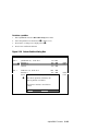
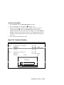
3-21
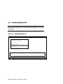
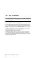
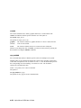
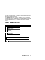
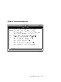
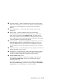
3.8
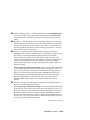
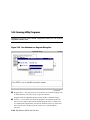
Installing Windows NT
Windows NT is installed from the CD-ROM. Insert the CD-ROM into the drive,
start AlphaBIOS Setup, select the menu item Install Windows NT, and follow
the prompts.
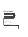
Figure 3–3 Installing Windows NT
AlphaBIOS Setup
Display System
AlphaBIOS Upgrade…
Hard Disk Setup…
CMOS Setup…
Network Setup…
Install Windows NT
Utilities
About AlphaBIOS…
8
Press ENTER to install Windows NT.
ESC = Exit
3-22
AlphaServer DS20 User’s Guide
F1= Help
Windows NT requires a partitioned and formatted hard disk drive. If your drive is
not partitioned or formatted, follow the instructions in Section 3.10 before installing
the Windows NT operating system.
Up to three versions of Windows NT can be resident in a system at one time.
If this is a new Windows NT installation, start with this procedure:
1.
Use CMOS Setup to set the system date and time: start AlphaBIOS Setup,
select CMOS Setup, and press Enter.
2.
Perform an express hard disk setup: return to the main AlphaBIOS Setup
screen, select Hard Disk Setup, and press Enter.
3.
Perform an express hard disk setup by pressing F7 to enter Express Setup.
4.
Continue the setup by pressing the F10 key.
5.
Go to the procedure below.
This procedure is for all Windows NT installations:
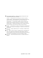
Read these instructions carefully paying particular attention to step 5.
1.
Put the Windows NT CD into the CD-ROM drive.
2.
Start AlphaBIOS Setup, select Install Windows NT, and press Enter.
3.
Windows NT 4.0 Setup incorrectly believes that it recognizes and supports the
unused onboard AIC-7895 SCSI controller and will load its driver unless it is
prevented from doing so. Your system’s CD-ROM is connected to a SCSI
controller on the PCI bus and its driver must be loaded. To prevent the loading
of the WRONG driver quickly press F6 when the Windows NT banner displays
(blue screen). If Windows NT autodetects the AIC-78xx and F6 was not pressed
at the right time, start over again. For further information, see the Windows NT
4.0 readme.txt file.
4.
To select the appropriate driver:
a.
Insert the AlphaServer DS20 Windows NT floppy into the floppy drive.
b.
If step 3 was successful, Windows NT Setup will announce that it cannot
determine the type of one or more mass storage controllers, press ’S’ to
specify an additional controller.
c.
From the list, choose “Other.” The floppy’s list will appear.
d.
Choose the “Adaptec AIC-78xx PCI SCSI Controller (NT4.0).”
Follow the prompts to complete the installation. For more information on installing
Windows NT, refer to the Installation Guide in your Windows NT software package.
Operation
3-23
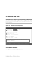
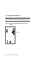
3.9
Switching Between Operating Systems
The system supports the use of multiple operating systems on different system
and data disks not in the machine at the same time; that is you can have a set of
disks for each operating system.
CAUTION: This operation is not for the faint hearted especially if you have a
shadow system disk and shadow arrays. The file structures of the three
operating systems are incompatible. Therefore all disks used by one
operating system must be removed when another is put in its place.
Upon reinstallation all disks must be placed in the same physical
locations. It is therefore necessary to keep track of the location of each
disk in the system.
3.9.1
Switching to Windows NT
Use the following procedure.
1.
Shut down the operating system and power off the system.
2.
Remove and mark the physical location of each disk in the system.
3.
Either place blank disks or your Windows NT disk set into the system. (If you
are placing a Windows NT disk set into the system, be sure that each disk is
replaced in the same physical location from which it was removed.)
4.
Power on the system.
5.
Enter the following commands at the SRM console prompt:
P00>>> set os_type nt
P00>>> init
6.
Either install Windows NT, see Section 3.8, or at the AlphaBIOS boot screen,
start AlphaBIOS setup (F2), select CMOS Setup, and press Enter.
7.
Set the system date and time.
8.
In CMOS Setup, check that the setup for the floppy and other basic parameters
are accurate. Set system-specific parameters, such as the memory test and
password, in Advanced CMOS Setup as needed. Press F10 to save the changes.
9.
From the AlphaBIOS Setup screen select Utilities. In the selection box, choose
OS Selection Setup. Make sure the selections (boot name, boot file, and so on)
are what you want. Press F10 to save the changes.
10. Return to the boot screen and boot Windows NT.
3-24
AlphaServer DS20 User’s Guide
3.9.2
Switching to DIGITAL UNIX or OpenVMS
Use the following procedure.
1.
Shut down the operating system and power off the system.
2.
Remove and mark the physical location of each disk in the system.
3.
Either place blank disks or your DIGITAL UNIX or OpenVMS disk set into the
system. No matter which disk set you are placing into the system, be sure
that each disk is placed in the same physical location from which it was
removed.
4.
Power on the system.
5.
In AlphaBIOS, access the Advanced CMOS Setup screen and change the
Console Selection to DIGITAL UNIX (SRM) or OpenVMS (SRM) as
appropriate. Press F10 to save the change. This menu selection changes the os_type environment variable to either UNIX or VMS so that the SRM console
does not load AlphaBIOS but remains in the system when you reset the system.
6.
Press the Reset button to reset the system.
7.
Either install DIGITAL UNIX (see Section 3.4 ) or OpenVMS (see Section 3.6)
or boot the operating system.
Operation
3-25
3.10
Updating Firmware
Start the Loadable Firmware Update (LFU) utility by issuing the lfu command
at the SRM console prompt, booting it from the CD-ROM while in the SRM
console, or selecting Update AlphaBIOS in the AlphaBIOS Setup screen.
Example 3–9 Starting LFU from the SRM Console
P00>>> lfu
***** Loadable Firmware Update Utility *****
Select firmware load device (cda0, dva0, ewa0), or
Press <return> to bypass loading and proceed to LFU: cda0
.
.
.
UPD>
Figure 3–4 Starting LFU from the AlphaBIOS Console
PK1461-98
3-26
AlphaServer DS20 User’s Guide
Use the Loadable Firmware Update (LFU) utility to update system firmware.
You can start LFU from either the SRM console or the AlphaBIOS console.
•
From the SRM console, start LFU by issuing the lfu command (see
Example 3–9). Also from the SRM console, LFU can be booted from the Alpha
CD-ROM (V5.4 or later), as shown in Example 3–10.
•
From the AlphaBIOS console, select Update AlphaBIOS from the AlphaBIOS
Setup screen (see Figure 3–4).
A typical update procedure is:
1.
Start LFU.
2.
Use the LFU list command to show the revisions of modules that LFU can
update and the revisions of update firmware.
3.
Use the LFU update command to write the new firmware.
4.
Use the LFU exit command to go back to the console.
Examples of updating firmware from CD-ROM, floppy, and the network follow.
Example 3–10 Booting LFU from the CD-ROM
P00>>> show device
➊
dka0.0.0.7.1
DKA0
RZ1DB-BA LYG0
dka100.1.0.7.1
DKA100
RZ1CB-CA LYJ0
dka500.5.0.7.1
DKA500
RRD47 1645
dva0.0.0.0.0
DVA0
ewa0.0.0.8.1
EWA0
00-00-F8-00-0E-3B
pka0.7.0.7.1
PKA0
SCSI Bus ID 7 5.54
P00>>> boot dka500
(boot dka500.5.0.7.1 -flags 0,0)
block 0 of dka500.5.0.7.1 is a valid boot block
.
.
jumping to bootstrap code
The default bootfile for this platform is
[AS1400]AS1400_LFU.EXE
Hit <RETURN> at the prompt to use the default bootfile.
Bootfile: <CR>
Starting Firmware Update Utility
***** Loadable Firmware Update Utility *****
.
UPD>
Operation
3-27
3.10.1
Updating Firmware from the CD-ROM
Insert the Alpha CD-ROM, start LFU, and select cda0 as the load device.
Example 3–11 Updating Firmware from the CD-ROM
***** Loadable Firmware Update Utility *****
Select firmware load device (cda0, dva0, ewa0), or
Press <return> to bypass loading and proceed to LFU: cda0
➊
Please enter the name of the options firmware files list, or
Press <return> to use the default filename [AS1400FW]: AS1400CP
➋
Copying
Copying
Copying
Copying
AS1400CP from DKA500.5.0.1.1 .
[AS1400]TCREADME from DKA500.5.0.1.1 .
[AS1400]TCSRMROM from DKA500.5.0.1.1 ....................
[AS1400]TCARCROM from DKA500.5.0.1.1 .............
----------------------------------------------------------------Function
Description
➌
----------------------------------------------------------------Display
Displays the system’s configuration table.
Exit
Done exit LFU (reset).
List
Lists the device, revision, firmware name, and
update revision.
Lfu
Restarts LFU.
Readme
Lists important release information.
Update
Replaces current firmware with loadable data image.
Verify
Compares loadable and hardware images.
? or Help
Scrolls this function table.
-----------------------------------------------------------------
➍
UPD> list
Device
Fsb
Nt
Pkx0
Srm
Pua
3-28
Current Revision
3.1-x
5.68
A11
5.4-x
A214
Filename
fsb_fw
nt_fw
kzpsa_fw
srm_fw
cipca_fw
AlphaServer DS20 User’s Guide
Update Revision
3.x
5.xx
A11
5.4-xx
A2xx
➊
Select the device from which firmware will be loaded. The choices are the
internal CD-ROM, the internal floppy disk, or a network device. In this
example, the internal CD-ROM is selected.
➋
Select the file that has the firmware update, or press Enter to select the default
file. The file options are:
AS1400FW
(default)
SRM console, AlphaBIOS console, and I/O adapter
firmware.
AS1400CP
SRM console and AlphaBIOS console firmware only.
AS1400IO
I/O adapter firmware only.
In this example the file for console firmware (AlphaBIOS and SRM) is
selected.
➌
➍
The LFU function table and prompt (UPD>) display.
Use the LFU list command to determine the revision of firmware in a device
and the most recent revision of that firmware available in the selected file. In
this example, the resident firmware for each console (SRM and AlphaBIOS) is
at an earlier revision than the firmware in the update file.
Continued on next page
Operation
3-29
Example 3–11 Updating Firmware from the CD-ROM (Continued)
UPD> update *
➎
WARNING: updates may take several minutes to complete for each
device.
Confirm update on: AlphaBIOS
AlphaBIOS
[Y/(N)] y
DO NOT ABORT!
Updating to V6.0-3... Verifying V6.0-3...
UPD> exit
3-30
➏
DO NOT ABORT!
Updating to V6.40-1... Verifying V6.40-1... PASSED.
Confirm update on: srmflash
srmflash
PASSED.
[Y/(N)] y
AlphaServer DS20 User’s Guide
➐
➎
The update command updates the device specified or all devices. In this
example, the wildcard indicates that all devices supported by the selected
update file will be updated.
➏
For each device, you are asked to confirm that you want to update the
firmware. The default is no. Once the update begins, do not abort the
operation. Doing so will corrupt the firmware on the module.
➐
The exit command returns you to the console from which you entered LFU
(either SRM or AlphaBIOS).
Operation
3-31
3.10.2
Updating Firmware from Floppy Disk — Creating
the Diskettes
Create the update diskettes before starting LFU. See Section 3.10.3 for an
example of the update procedure.
Table 3–1 File Locations for Creating Update Diskettes on a PC
Console Update Diskette
I/O Update Diskette
AS1400FW.TXT
AS1400IO.TXT
AS1400CP.TXT
TCREADME.SYS
TCREADME.SYS
CIPCA315.SYS
TCSRMROM.SYS
DFPAA310.SYS
TCARCROM.SYS
KZPAAA11.SYS
To update system firmware from floppy disk, you first must create the firmware
update diskettes. You will need to create two diskettes: one for console updates, and
one for I/O.
1.
Download the update files from the Internet.
2.
On a PC, copy files onto two FAT-formatted diskettes as shown in Table 3–1.
3.
From an OpenVMS system, copy files onto two ODS2-formatted diskettes as
shown in Example 3–12.
3-32
AlphaServer DS20 User’s Guide
Example 3–12 Creating Update Diskettes on an OpenVMS
System
Console update diskette
$
$
$
$
$
$
$
$
$
$
$
$
$
$
inquire ignore "Insert blank HD floppy in DVA0, then continue"
set verify
set proc/priv=all
init /density=hd/index=begin dva0: tcods2cp
mount dva0: tcods2cp
create /directory dva0:[as1400]
copy tcreadme.sys dva0:[as1400]tcreadme.sys
copy AS1400fw.txt dva0:[as1400]as1400fw.txt
copy AS1400cp.txt dva0:[as1400]as1400cp.txt
copy tcsrmrom.sys dva0:[as1400]tcsrmrom.sys
copy tcarcrom.sys dva0:[as1400]tcarcrom.sys
dismount dva0:
set noverify
exit
I/O update diskette
$
$
$
$
$
$
$
$
$
$
$
$
$
$
$
$
inquire ignore "Insert blank HD floppy in DVA0, then continue"
set verify
set proc/priv=all
init /density=hd/index=begin dva0: tcods2io
mount dva0: tcods2io
create /directory dva0:[as1400]
create /directory dva0:[options]
copy tcreadme.sys dva0:[as1400]tcreadme.sys
copy AS1400fw.txt dva0:[as1400]as1400fw.txt
copy AS1400io.txt dva0:[as1400]as1400io.txt
copy cipca214.sys dva0:[options]cipca214.sys
copy dfpaa246.sys dva0:[options]dfpaa246.sys
copy kzpsaA10.sys dva0:[options]kzpsaa10.sys
dismount dva0:
set noverify
exit
Operation
3-33
3.10.3
Updating Firmware from Floppy Disk — Performing
the Update
Insert an update diskette (see Section 3.10.2) into the floppy drive. Start LFU
and select dva0 as the load device.
Example 3–13 Updating Firmware from the Floppy Disk
***** Loadable Firmware Update Utility *****
Select firmware load device (cda0, dva0, ewa0), or
Press <return> to bypass loading and proceed to LFU: dva0
➊
Please enter the name of the options firmware files list, or
Press <return> to use the default filename [AS1400IO,(AS1400CP)]:
AS1400IO
➋
Copying AS1400IO from DVA0 .
Copying TCREADME from DVA0 .
Copying CIPCA214 from DVA0 .
Copying DFPAA252 from DVA0 ...
Copying KZPSAA11 from DVA0 ...
.
. [The function table displays, followed by the UPD> prompt, as
. shown in Example 3–11.]
➌
UPD> list
Device
Fsb
Nt
Pkx0
Srm
Pua
3-34
Current Revision
3.1-x
5.68
A11
5.4-x
A214
Filename
fsb_fw
nt_fw
kzpsa_fw
srm_fw
cipca_fw
AlphaServer DS20 User’s Guide
Update Revision
3.x
5.xx
A11
5.4-xx
A2xx
➊
Select the device from which firmware will be loaded. The choices are the
internal CD-ROM, the internal floppy disk, or a network device. In this
example, the internal floppy disk is selected.
➋
Select the file that has the firmware update, or press Enter to select the default
file. When the internal floppy disk is the load device, the file options are:
AS1400CP (default)
SRM console and AlphaBIOS console firmware only.
AS1400IO
I/O adapter firmware only.
The default option in Example 3–11 (AS1400FW) is not available, since the
file is too large to fit on a 1.44 MB diskette. This means that when a floppy
disk is the load device, you can update either console firmware or I/O adapter
firmware, but not both in the same LFU session. If you need to update both,
after finishing the first update, restart LFU with the lfu command and insert the
diskette with the other file.
In this example the file for I/O adapter firmware is selected.
➌
Use the LFU list command to determine the revision of firmware in a device
and the most recent revision of that firmware available in the selected file. In
this example, the update revision for console firmware displays as “Missing
file” because only the I/O firmware files are available on the floppy disk.
Continued on next page
Operation
3-35
Example 3–13 Updating Firmware from the Floppy Disk
(Continued)
UPD> update pfi0
➍
WARNING: updates may take several minutes to complete for each device.
Confirm update on: pfi0
[Y/(N)] y
➎
DO NOT ABORT!
Updating to 3.10... Verifying to 3.10... PASSED.
pfi0
➏
UPD> lfu
***** Loadable Firmware Update Utility *****
Select firmware load device (cda0, dva0, ewa0), or
Press <return> to bypass loading and proceed to LFU: dva0
Please enter the name of the options firmware files list, or
Press <return> to use the default filename [AS1400IO,(AS1400CP)]:➐
.
. (The function table displays, followed by the UPD> prompt.
. Console firmware can now be updated.)
UPD> exit
3-36
AlphaServer DS20 User’s Guide
➑
➍
➎
The update command updates the device specified or all devices.
➏
The lfu command restarts the utility so that console firmware can be updated.
(Another method is shown in Example 3–14, where the user specifies the file
AS1400FW and is prompted to insert the second diskette.)
➐
The default update file, AS1400CP, is selected. The console firmware can now
be updated, using the same procedure as for the I/O firmware.
➑
The exit command returns you to the console from which you entered LFU
(either SRM or AlphaBIOS).
For each device, you are asked to confirm that you want to update the
firmware. The default is no. Once the update begins, do not abort the
operation. Doing so will corrupt the firmware on the module.
Example 3–14 Selecting AS1400FW to Update Firmware from the
Internal Floppy Disk
P00>>> lfu
***** Loadable Firmware Update Utility *****
Select firmware load device (cda0, dva0, ewa0), or
Press <return> to bypass loading and proceed to LFU: dva0
Please enter the name of the firmware files list, or
Press <return> to use the default filename [AS1400IO,(AS1400CP)]: AS1400fw
Copying AS1400FW from DVA0 .
Copying TCREADME from DVA0 .
Copying TCSRMROM from DVA0 ..........................
Copying TCARCROM from DVA0 ...............
Copying CIPCA214 from DVA0
Please insert next floppy containing the firmware,
Press <return> when ready. Or type DONE to abort.
Copying CIPCA214 from DVA0 .
Copying DFPAA246 from DVA0 ...
Copying KZPSAA10 from DVA0 ...
.
.
.
Operation
3-37
3.10.4
Updating Firmware from a Network Device
Copy files to the local MOP server’s MOP load area, start LFU, and select ewa0
as the load device.
Example 3–15 Updating Firmware from a Network Device
***** Loadable Firmware Update Utility *****
Select firmware load device (cda0, dva0, ewa0), or
Press <return> to bypass loading and proceed to LFU: ewa0
➊
Please enter the name of the options firmware files list, or
Press <return> to use the default filename [AS1400FW]:
➋
Copying
Copying
Copying
Copying
Copying
Copying
Copying
AS1400FW
TCREADME
TCSRMROM
TCARCROM
CIPCA214
DFPAA246
KZPSAA11
from
from
from
from
from
from
from
EWA0
EWA0
EWA0
EWA0
EWA0
EWA0
EWA0
.
.
...........................
............
.
...
...
.
. [The function table displays, followed by the UPD> prompt, as
. shown in Example 3–11.]
➌
UPD> list
Device
Fsb
Nt
Pkx0
Srm
Pua
Current Revision
3.1-x
5.68
A11
5.4-x
A214
Filename
fsb_fw
nt_fw
kzpsa_fw
srm_fw
cipca_fw
Update Revision
3.x
5.xx
A11
5.4-xx
A2xx
Continued on next page
3-38
AlphaServer DS20 User’s Guide
Before starting LFU, download the update files from the Internet. You will need the
files with the extension .SYS. Copy these files to your local MOP server’s MOP load
area.
➊
Select the device from which firmware will be loaded. The choices are the CDROM, the internal floppy disk, or a network device. In this example, a network
device is selected.
➋
Select the file that has the firmware update, or press Enter to select the default
file. The file options are:
AS1400FW
(default)
SRM console, AlphaBIOS console, and I/O adapter
firmware.
AS1400CP
SRM console and AlphaBIOS console firmware only.
AS1400IO
I/O adapter firmware only.
In this example the default file, which has both console firmware (AlphaBIOS
and SRM) and I/O adapter firmware, is selected.
➌
Use the LFU list command to determine the revision of firmware in a device
and the most recent revision of that firmware available in the selected file. In
this example, the resident firmware for each console (SRM and AlphaBIOS)
and I/O adapter is at an earlier revision than the firmware in the update file.
Continued on next page
Operation
3-39
Example 3–15 Updating Firmware from a Network Device
(Continued)
UPD> update * -all
➍
WARNING: updates may take several minutes to complete for each
device.
AlphaBIOS
DO NOT ABORT!
Updating to V6.40-1... Verifying V6.40-1... PASSED.
kzpsa0
DO NOT ABORT!
Updating to A11
... Verifying A11... PASSED.
kzpsa1
DO NOT ABORT!
Updating to A11
... Verifying A11... PASSED.
srmflash
DO NOT ABORT!
Updating to V6.0-3... Verifying V6.0-3... PASSED.
UPD> exit
3-40
AlphaServer DS20 User’s Guide
➎
➍
The update command updates the device specified or all devices. In this
example, the wildcard indicates that all devices supported by the selected
update file will be updated. Typically LFU requests confirmation before
updating each console’s or device’s firmware. The -all option eliminates the
update confirmation requests.
➎
The exit command returns you to the console from which you entered LFU
(either SRM or AlphaBIOS).
Operation
3-41
3.10.5
LFU Commands
The commands summarized in Table 3–2 are used to update system firmware.
Table 3–2 LFU Command Summary
Command
Function
display
Shows the physical configuration of the system.
exit
Terminates the LFU program.
help
Displays the LFU command list.
lfu
Restarts the LFU program.
list
Displays the inventory of update firmware on the selected device.
readme
Lists release notes for the LFU program.
update
Writes new firmware to the module.
verify
Reads the firmware from the module into memory and compares it
with the update firmware.
These commands are described in the following pages.
3-42
AlphaServer DS20 User’s Guide
display
The display command shows the physical configuration of the system. Display is
equivalent to issuing the SRM console command show configuration. Because it
shows the slot for each module, display can help you identify the location of a
device.
exit
The exit command terminates the LFU program, causes system initialization and
testing, and returns the system to the console from which LFU was called.
help
The help (or ?) command displays the LFU command list,
shown below.
--------------------------------------------------------------------Function
Description
--------------------------------------------------------------------Display
Displays the system’s configuration table.
Exit
Done exit LFU (reset).
List
Lists the device, revision, firmware name, and update
revision.
Lfu
Restarts LFU.
Readme
Lists important release information.
Update
Replaces current firmware with loadable data image.
Verify
Compares loadable and hardware images.
? or Help Scrolls this function table.
---------------------------------------------------------------------
lfu
The lfu command restarts the LFU program. This command is used when the update
files are on a floppy disk. The files for updating both console firmware and I/O
firmware are too large to fit on a 1.44 MB disk, so only one type of firmware can be
updated at a time. Restarting LFU enables you to specify another update file.
Operation
3-43
list
The list command displays the inventory of update firmware on the CD-ROM,
network, or floppy. Only the devices listed at your terminal are supported for
firmware updates.
The list command shows three pieces of information for each device:
•
Current Revision — The revision of the device’s current firmware
•
Filename — The name of the file used to update that firmware
•
Update Revision — The revision of the firmware update image
readme
The readme command lists release notes for the LFU program.
update
The update command writes new firmware to the module. Then LFU automatically
verifies the update by reading the new firmware image from the module into
memory and comparing it with the source image.
To update more than one device, you may use a wildcard but not a list. For example,
update k* updates all devices with names beginning with k, and update * updates
all devices. When you do not specify a device name, LFU tries to update all devices;
it lists the selected devices to update and prompts before devices are updated. (The
default is no.) The -all option eliminates the update confirmation requests, enabling
the update to proceed without operator intervention.
CAUTION: Never abort an update operation. Aborting corrupts the firmware on
the module.
verify
The verify command reads the firmware from the module into memory and
compares it with the update firmware. If a module already verified successfully when
you updated it, but later failed tests, you can use verify to tell whether the firmware
has become corrupted.
3-44
AlphaServer DS20 User’s Guide
3.11
Hard Disk Partitioning for Windows NT
The recommended hard disk partition on the first hard disk in your system is:
partition 1 should be 6 megabytes less than the total size of the drive (this large
partition holds the operating system and the application and data files) and
partition 2 should be the remaining 6 megabytes (this small partition holds only
the few files necessary for your computer to boot).
This arrangement provides two benefits:
•
AlphaBIOS requires that a boot partition be formatted with the FAT file system.
However, the Windows NT file system (NTFS) provides advantages over FAT,
such as additional security and more efficient use of disk space. By keeping the
FAT boot partition as small as possible, the maximum amount of space is left
available for use as an NTFS partition.
•
Most applications install themselves onto drive C by default. Although the
program installation drive is usually configurable by the user, many people
accept the default of drive C. By making the first partition large, drive C
becomes the larger drive. This arrangement makes program installation easier
and avoids time-consuming insufficient disk space mistakes.
3.11.1
Hard Disk Error Conditions
Disk Initialization Failed
When you start hard disk setup, if you receive an “Internal error occurred” message,
it means that a disk was found, but there was an error in communicating with the
disk. The likely conditions that can cause this error are:
•
Incompatible or failed disk cables. You may not have the correct cable installed,
or the cable might have a broken lead or connector. Try another cable known to
be good.
•
Disk controller not configured. You may have to run a configuration utility to
set up your hard disk controller. Check your controller documentation.
•
Disk controller malfunction. Most controllers come with a diagnostic utility to
test controller functioning. If a controller error is found, call the manufacturer
for a replacement.
•
Improper SCSI termination. Many SCSI controllers require that the terminating
resistor packs be removed from all drives between the controller and last drive.
Only the controller itself, and the last drive connected to the controller (the ends
of the “chain”), should have terminating resistor packs left on.
Operation
3-45
No Hard Disks Found
When you start hard disk setup, if you receive a “No hard drives were found
connected to your computer” message, it means that AlphaBIOS could not locate a
hard drive. The likely conditions that cause this error are:
•
Cable not connected to either the disk or controller. The cable may have worked
loose from the connector on the controller or disk drive. Check the cable
connections, making sure the cable connectors are fully seated.
•
No power to the drive. The power connector may have worked loose from the
receptacle on the drive, or the power cable itself may be malfunctioning. Check
the cable connections, making sure the cable connectors are fully seated. Try
connecting the drive to a different power connector.
•
Disk drive malfunction. The disk drive itself may be malfunctioning and not
responding to requests from the controller. If this is the problem, then it would
appear as though the disk were absent. Replace the drive with a drive known to
be good. If the known good drive is correctly detected, then your hard drive is
defective. Contact the manufacturer for a replacement.
No Partitions on Disk
If hard disk 0 does not have any partitions defined, then a message will appear when
you start hard disk setup, asking if you want to perform an express disk setup.
Express disk setup automatically creates the default disk partition arrangement on
hard disk 0.
For more information on express setup, see Chapter 5.
3.11.2
System Partitions
To install Windows NT, a system partition must be defined. If no system partition is
found, the user is asked to choose from the available FAT partitions.
The purpose of the system partition is twofold. First, it tells the Windows NT
installation program where to place the OS Loader and hardware support files.
Second, upon subsequent restarts of Windows NT, the system partition definition
tells AlphaBIOS where the OSLOADER.EXE file is so it can successfully hand off
control to the OS Loader and continue the boot process.
The system partition can be the same partition into which Windows NT is installed,
or it can be separate. However, the system partition must be formatted with the FAT
file system. Because the default recommended partition arrangement on Alpha calls
for the partition into which Windows NT is installed to be an NTFS partition, the
system partition will almost always be a small FAT partition on the same disk onto
which Windows NT is installed.
3-46
AlphaServer DS20 User’s Guide
3.11.3
How AlphaBIOS Works with System Partitions
If you are installing Windows NT for the first time, AlphaBIOS will determine that a
system partition has not been defined when you select Install Windows NT in the
AlphaBIOS Setup screen (see Figure 3–5). When this occurs, AlphaBIOS searches
for all FAT partitions on the system. If only one FAT partition exists, AlphaBIOS
designates that FAT partition as the system partition and continues with the
Windows NT installation. If more than one FAT partition exists on your system,
AlphaBIOS displays the list of FAT partitions from which you can choose the system
partition. After choosing the system partition, the installation process continues.
Figure 3–5 System Partition Not Defined
AlphaBIOS Setup
Display System Configuration
Upgrade AlphaBIOS
Hard Disk Setup
CMOS s
No System Partition
Instal
Utilit You must designate a FAT disk partition as
About
Partition. Windows NT will use the System
a System
Partition
to store system specific startup files.
Please select a partition as the System Partition.
System Partition:
ENTER
=Con
Disk 0, Partition 1
Disk
Disk
Disk
Disk
0,
0,
1,
1,
Partition
Partition
Partition
Partition
Ò
1
2
1
2
Operation
3-47
3.12
Using the Halt Button
Use the Halt button to halt the DIGITAL UNIX or OpenVMS operating system
when it hangs, clear the SRM console password, or force a halt assertion, as
described in Section 3.12.
Using Halt to Shut Down the Operating System
You can use the Halt button if the DIGITAL UNIX or OpenVMS operating system
hangs. Pressing the Halt button halts the operating system back to the SRM console
firmware. From the console, you can use the crash command to force a crash dump
at the operating system level. See Section 4.11 for an example.
The Windows NT operating system does not support halts on this system. Pressing
the Halt button during a Windows NT session has no effect.
Using Halt to Clear the Console Password
The SRM console firmware allows you to set a password to prevent unauthorized
access to the console. If you forget the password, the Halt button, with the login
command, lets you clear the password and regain control of the console. Section 4.8
describes the procedure (page 4-29).
3-48
AlphaServer DS20 User’s Guide
3.13
Halt Assertion
A halt assertion allows you to disable automatic boots of the operating system so
that you can perform tasks from the SRM console.
Under certain conditions, you might want to force a “halt assertion.” A halt assertion
differs from a simple halt in that the SRM console “remembers” the halt. The next
time you power up, the system ignores the SRM power-up script (nvram) and ignores
any environment variables that you have set to cause an automatic boot of the
operating system. The SRM console displays this message:
Halt assertion detected
NVRAM power-up script not executed
AUTO_ACTION=BOOT/RESTART and OS_TYPE=NT ignored, if applicable
Halt assertion is useful for disabling automatic boots of the operating system when
you want to perform tasks from the SRM console. It is also useful for disabling the
SRM power-up script if you have accidentally inserted a command in the script that
will cause a system problem. These conditions are described in the sections
“Disabling Autoboot” and “Disabling the SRM Power-Up Script.”
You can force a halt assertion using the Halt button, the RCM halt command, or the
RCM haltin command. Observe the following guidelines for forcing a halt
assertion.
Halt Assertion with Halt Button or RCM Halt Command
Press the Halt button on the local system (or enter the RCM halt command from a
remote system) approximately five seconds after starting power up or when the SRM
console is running. The system halts at the SRM console, and the halt status is
saved. The next time the system powers up, the saved halt status is checked.
NOTE: Wait 5 seconds after the system begins powering up before pressing the Halt
button or remotely entering the RCM halt command. Press the button for
several seconds.
Halt Assertion with RCM Haltin Command
Enter the RCM haltin command at any time except during power-up. For example,
enter haltin during an operating system session or when the AlphaBIOS console is
running.
If you enter the RCM haltin command during a DIGITAL UNIX or OpenVMS
session, the system halts back to the SRM console, and the halt status is saved. The
next time the system powers up, the saved halt status is checked.
Operation
3-49
If you enter the RCM haltin command when Windows NT or AlphaBIOS is running,
the interrupt is ignored. However, you can enter the RCM haltin command followed
by the RCM reset command to force a halt assertion. Upon reset, the system powers
up to the SRM console, but the SRM console does not load the AlphaBIOS console.
Clearing a Halt Assertion
Clear a halt assertion as follows:
•
If the halt assertion was caused by pressing the Halt button or remotely entering
the RCM halt command, the console uses the halt assertion once, then clears it.
•
If the halt assertion was caused by entering the RCM haltin command, enter the
RCM haltout command or cycle power on the local system.
Disabling Autoboot
The system automatically boots the selected operating system at power-up or reset if
the following environment variables are set:
•
For DIGITAL UNIX and OpenVMS, the SRM environment variables os_type,
auto_action, bootdef_dev, boot_file, and boot_osflags
•
For Windows NT, the SRM os_type environment variable and the Auto Start
selection in the AlphaBIOS Standard CMOS Setup screen
You might want to prevent the system from autobooting so you can perform tasks
from the SRM console. Use one of the methods described previously to force a halt
assertion. When the SRM console prompt is displayed, you can enter commands to
configure or test the system. Chapter 4 describes the SRM console commands and
environment variables.
Disabling the SRM Power-Up Script
The system has a power-up script (file) named “nvram” that runs every time the
system powers up. If you accidentally insert a command in the script that will cause
a system problem, disable the script by using one of the methods described
previously to force a halt assertion. When the SRM console prompt is displayed,
edit the script to delete the offending command. See Section 4.4 for more
information on editing the nvram script.
3-50
AlphaServer DS20 User’s Guide
Chapter 4
SRM Console
The SRM console is the command line interface that supports the DIGITAL UNIX
and OpenVMS operating systems. The SRM console is used to bootstrap the
operating system, configure and test the system hardware, examine system options for
errors, and set or change environment variables.
This chapter describes the SRM commands and environment variables. Sections in
this chapter are:
•
Invoking the SRM Console
•
Command Summary
•
Displaying the System Configuration
•
Creating a Power-Up Script
•
Booting the Operating System
•
Configuring the System
•
Testing the System
•
Making the System Secure
•
Stopping and Starting CPUs
•
Updating Firmware
•
Forcing a System Crash Dump
•
Using Environment Variables
•
Depositing and Examining Data
•
Reading a File
•
Initializing the System
•
Finding Help
•
Switching from SRM to AlphaBIOS Console
•
Environment Variable Summary
SRM Console
4-1
4.1
Invoking the SRM Console
When a system is powered up, the SRM console runs and either remains running
or passes control to another console or an operating system. If the system is
already running, invoke the SRM console by shutting down the operating system
or by pressing the Halt button on the control panel.
In a system running the DIGITAL UNIX or OpenVMS Alpha operating system, do
one of the following steps to invoke the SRM console mode:
•
Shut down the operating system according to the procedure described in your
operating system documentation. The SRM console prompt, P00>>>, will be
displayed.
•
Press the Halt button on the control panel, if your system is running either
OpenVMS or DIGITAL UNIX. The console prompt, P00>>>, will be displayed.
If you are in AlphaBIOS and want to switch to the SRM console, do one of the
following steps:
•
Select either OpenVMS console (SRM) or DIGITAL UNIX console (SRM)
from the Console Selection in the Advanced CMOS Setup screen. Save the
setting by pressing the F10 key and reset the system to start the SRM console.
•
Press the Reset button, wait 5 seconds, and then press the Halt button. The SRM
console will boot.
After you have performed tasks in the console mode, you must boot the operating
system with the boot command to go back to the operating mode.
4-2
AlphaServer DS20 User’s Guide
4.2
Command Summary
The SRM (Alpha System Reference Manual) console is a command line interface
used when the operating system is either DIGITAL UNIX or OpenVMS. Console
commands enable the user to examine and modify the system state.
Table 4-1 gives the most commonly used SRM console commands.
Table 4-2 gives the syntax for the console commands.
Table 4-3 gives special characters you can use in console mode.
Table 4-1 Summary of SRM Console Commands
Command
Function
alphabios
Loads and starts the AlphaBIOS console.
boot
Loads and starts the operating system.
clear envar
Resets an environment variable to its default value.
clear password
Sets the password to zero.
continue
Resumes program execution.
crash
Forces a crash dump at the operating system level.
deposit
Writes data to the specified address.
edit
Invokes the console line editor on a RAM file or on the nvram file
(power-up script).
examine
Displays the contents of a memory location, register, or device.
halt
Halts the specified processor. (Same as stop.)
help
Displays information about the specified console command.
initialize
Resets the system to a known state.
isacfg
Displays or modifies parameters for ISA devices.
lfu
Runs the Loadable Firmware Update Utility.
login
Turns off secure mode, enabling access to all SRM console
commands during the current session.
Continued on next page
SRM Console
4-3
Table 4-1 Summary of SRM Console Commands (Continued)
Command
Function
more
Displays a file one screen at a time.
prcache
Utility that initializes and displays status of the optional PCI
NVRAM device.
set envar
Sets or modifies the value of an environment variable.
set host
Connects to an MSCP DUP server on a DSSI device.
set password
Sets the console password for the first time or changes an existing
password.
set secure
Enables secure mode without requiring a restart of the console.
show envar
Displays the state of the specified environment variable.
show config
Displays the configuration at the last system initialization.
show cpu
Displays the state of each processor in the system.
show device
Displays a list of controllers and their devices in the system.
show memory
Displays memory module information.
show pal
Displays the version of the privileged architecture library code
(PALcode).
show power
Displays information about the power supplies, system fans, CPU
fans, and temperature.
show version
Displays the version of the console program.
stop
Halts the specified processor. (Same as halt.)
test
Runs firmware diagnostics for the system.
4-4
AlphaServer DS20 User’s Guide
Table 4-2 Syntax for SRM Console Commands
Parameter
Attribute or Action
Length
Up to 255 characters, not including the terminating carriage return
or any characters deleted as the command is entered. A command
longer than 80 characters and without the backslash character (see
Table 4-3) causes display of an error message.
Case
Upper- or lowercase characters can be used for input. Characters
are displayed in the case in which they are entered.
Abbreviation
Only by dropping characters from the end of words. You must enter
the minimum number of characters to identify the keyword
unambiguously. Abbreviation of environment variables is allowed
with the show command.
Options
You can use command options, to modify the environment, after
the command keyword or after any symbol or number in the
command. See individual command descriptions for examples.
Numbers
Most numbers in console commands are in decimal notation. Two
exceptions, both of which use hexadecimal notation, are addresses
and numbers used in the deposit command. The default radix can
be overridden by inserting %d before numbers you want to express
in decimal, %b before binary, %o before octal, or %x before
hexadecimal. Register names (for example, R0) are not considered
numbers and use decimal notation.
No characters
A command line with no characters is a null command. The
console program takes no action and does not issue an error
message; it returns the console prompt. The console supports
command line recall and editing.
Spaces or tabs
Multiple adjacent spaces and tabs are compressed and treated as a
single space. The console program ignores leading and trailing
spaces.
SRM Console
4-5
Table 4-3 Special Characters for SRM Console
Character
Function
Return or Enter
Terminates a command line. No action is taken on a
command until it is terminated. If no characters are entered
and this key is pressed, the console just redisplays the
prompt.
Backslash (\)
Continues a command on the next line. Must be the last
character on the line to be continued.
Delete
Deletes the previous character.
Help
By itself, displays first-level help. When pressed after part of
a command, displays options available.
Ctrl/A or F14
Toggles between insert and overstrike modes. The default is
overstrike.
Ctrl/B or up-arrow
Recalls previous command or commands. The last 16
commands are stored in the recall buffer.
Ctrl/C or Ctrl/P
Terminates the process that is running. Clears Ctrl/S; resumes
output suspended by Ctrl/O. When entered as part of a
command line, deletes the current line. Ctrl/C has no effect as
part of a binary data stream.
Ctrl/D or left-arrow
Moves the cursor left one position.
Ctrl/E
Moves the cursor to the end of the line.
Ctrl/F or right-arrow
Moves the cursor right one position.
Ctrl/H or Backspace
or F12
Moves the cursor to the beginning of the line.
Ctrl/J
Deletes the previous word.
Ctrl/O
Stops output to the console terminal for the current
command. Toggles between enable and disable. The output
can be reenabled by other means as well: when the console
prompts for a command, issues an error message, or enters
program mode, or when Ctrl/P is entered.
Ctrl/Q
Resumes output to the console terminal that was suspended
by Ctrl/S.
4-6
AlphaServer DS20 User’s Guide
Table 4-3 Special Characters for SRM Console (Continued)
Character
Function
Ctrl/R
Redisplays the current line. Deleted characters are omitted.
This command is useful for hardcopy terminals.
Ctrl/S
Suspends output to the console terminal until Ctrl/Q is
entered. Cleared by Ctrl/C.
Ctrl/U
Deletes the current line.
*
Wildcarding for commands such as show.
""
Double quotes enable you to denote a string for environment
variable assignment.
#
Specifies that all text between it and the end of the line is a
comment. Control characters are not considered part of a
comment.
SRM Console
4-7
4.3
Displaying the System Configuration
Several commands are used to display the system configuration: show config,
show cpu, show device, show memory, show pal, show power, and show version.
Example 4–1 Show Config Command
P00>>> show config
AlphaPC 264DP 500 MHz
SRM Console:
V5.4-x
PALcode:
OpenVMS PALcode V1.42-32, Digital UNIX PALcode V1.40-35
Processors
CPU 0
Alpha 21264-3 500 MHz
SROM Revision: V1.82
Bcache size: 4 MB
CPU 1
Alpha 21264-4 500 MHz
SROM Revision: V1.82
Bcache size: 4 MB
Core Logic
Cchip
DECchip 21272-CA Rev 2
Dchip
DECchip 21272-DA Rev 2
Pchip 0
DECchip 21272-EA Rev 2
Pchip 1
DECchip 21272-EA Rev 2
TIG
Rev 4.11
Arbiter
Rev 2.8 (0x1)
MEMORY
Array #
Size
Base Addr
1
128 MB
000000000
Total Bad Pages = 0
Total Good Memory = 128 MBytes
PCI Hose 00
Bus 00
Slot 05/0: Cypress 82C693
Bus 00
Slot 05/1: Cypress 82C693 IDE
Bus 00
Slot 05/2: Cypress 82C693 IDE
Bridge to Bus 1, ISA
dqa.0.0.105.0
dqb.0.1.205.0
Continued on next page
4-8
AlphaServer DS20 User’s Guide
Bus 00
Slot 05/3: Cypress 82C693 USB
Bus
Bus
Bus
Bus
00
00
00
00
PCI Hose 01
Bus 00
Slot
Slot
Slot
Slot
06/0: Adaptec AIC-7895
06/1: Adaptec AIC-7895
08: 00E31091
09: Cirrus CL-GD5430
Slot 07: DECchip 21152-AA
Bridge to Bus 2,
PCI
Bus 02
Slot 00: NCR 53C875
pka0.7.0.2000.1
dka0.0.0.2000.1
Bus 02
Bus 02
ISA
Slot
DMA
0
SCSI Bus ID 7
RZ1CB-CS
Slot 01: NCR 53C875
pkb0.7.0.2001.1
dkb500.5.0.2001.1
Slot 02: DE500-AA Network Controller
ewa0.0.0.2002.1
Device
Name
Type
0
1
2
3
4
5
MOUSE
KBD
COM1
COM2
LPT1
FLOPPY
Embedded
Embedded
Embedded
Embedded
Embedded
Embedded
Enabled
Yes
Yes
Yes
Yes
Yes
Yes
SCSI Bus ID 7
RRD47
00-06-2B-00-13-47
BaseAddr
60
60
3f8
2f8
3bc
3f0
IRQ
12
1
4
3
7
6
2
P00>>>
The show config command displays a list of devices found on the system interconnect
and I/O buses. This is the configuration at the most recent initialization. The syntax is:
show config
Example 4–2 Show CPU Command
P00>>> show cpu
Primary CPU:
Active CPUs:
Configured CPUs:
SROM Revision:
P00>>>
00
00
01
00
01
X1.82 X1.82
The show cpu command displays the status of each CPU. The syntax is:
show cpu
SRM Console
4-9
Example 4–3 Show Device Command
P00>>> show device
dkc0.0.0.9.0
dkc100.1.0.9.0
dkc200.2.0.9.0
dkc300.3.0.9.0
dkc500.5.0.9.0
dva0.0.0.0.0
ewa0.0.0.8.1
pkc0.7.0.9.0
P00>>>
DKC0
DKC100
DKC200
DKC300
DKC500
DVA0
EWA0
PKC0
RZ1DB-BA
RZ1CB-CA
RZ1CB-CA
RZ1CB-CA
RRD47
LYG0
LYJ0
LYJ0
LYJ0
1337
00-00-F8-00-0E-3B
SCSI Bus ID 7 5.54
The show device command displays status for devices and controllers in the system:
SCSI and MSCP devices, the internal floppy drive, and the network. The syntax is:
show device [controller_name]
controller_name
The controller name or abbreviation. When abbreviations or
wildcards are used, all controllers that match the type are
displayed. If no name is given, the display is a list of all
devices and controllers in the system.
An example of a device name is dka200.2.0.7.1. Table 4-4 shows the interpretation of
this device name.
.
4-10
AlphaServer DS20 User’s Guide
Table 4-4 Device Naming Convention
dk
Category
Description
Driver ID
Two-letter designator of port or class driver
dk
SCSI device
fw
FDDI device
dq
ATAPI CD-ROM
mk
SCSI tape
dr
RAID set device
mu
DSSI tape
du
DSSI disk
pk
SCSI port
dv
Diskette drive
pu
DSSI port
ew
Ethernet port
a
Storage adapter ID
One-letter designator of storage adapter (a, b, c...).
200
Device unit number
Unique number (MSCP unit number). SCSI unit
numbers are forced to 100 X node ID.
2
Bus node number
Bus node ID.
0
Channel number
Used for multi-channel devices.
7
Logical slot number
Corresponds to PCI slot number, as shown in
Table 4-5.
1
Hose number
0 — PCI 0
1 — PCI 1
Table 4-5 PCI Address Assignments
Slot
PCI 0
PCI 1
5
ISA bridge (on board)
6
Adaptec SCSI (on board)
7
PCI device
PCI device
8
PCI device
PCI device
9
PCI device
PCI device
ISA
ISA device
SRM Console
4-11
Example 4–4 Show Memory Command
P00>>> show memory
Array #
------0
1
2
3
Size
---------128 MB
128 MB
128 MB
128 MB
Base Addr
--------000000000
008000000
010000000
018000000
Total Bad Pages = 0
Total Good Memory = 512 MBytes
P00>>>
The show memory command displays information about each memory bank: slot
number, size in megabytes, and the starting address. The syntax is:
show memory
Example 4–5 Show PAL Command
P00>>> show pal
pal OpenVMS PALcode V1.31-27, DIGITAL UNIX PALcode V1.27-31
P00>>>
The show pal command displays the versions of DIGITAL UNIX and OpenVMS
PALcode. PALcode is the Alpha Privileged Architecture Library code, written to
support Alpha processors. It implements architecturally defined processor behavior.
The syntax is:
show pal
4-12
AlphaServer DS20 User’s Guide
Example 4–6 Show Power Command
P00>>> show power
Power Supply 0
Power Supply 1/Fan Tray
System Fans
CPU Fans
Temperature
Status
good
good
good
good
good
Current ambient temperature is 27 degrees C
System shutdown temperature is set to 55 degrees C
2 Environmental events are logged in nvram
Do you want to view the events? (Y/<N>) y
Total Environmental Events: 2 (2 logged)
1
2
000
000
0
0
0:00
0:00
Temperature, Fans, Power Supplies Normal
Temperature, Fans, Power Supplies Normal
Do you want to clear all events from nvram? (Y/<N>) y
P00>>>
The show power command displays status information about the power supplies,
system fans, CPU fans, and temperature. This command is useful for displaying the
error state of a DIGITAL UNIX or OpenVMS system that shuts down because of a
fan, temperature, or power supply failure. If the system can be restarted, use this
command. (If it cannot, use the RCM status command. See Chapter 6.)
The syntax is:
show power
SRM Console
4-13
Example 4–7 Show Version Command
P00>>> show version
version
P00>>>
V5.4-x NOV 20 1998 13:59:28
The show version command displays the version of the SRM console program that is
installed on the system. The syntax is:
show version
4-14
AlphaServer DS20 User’s Guide
4.4
Creating a Power-Up Script
The system comes with a special nonvolatile file named “nvram” that is stored in
EEROM. Nvram is a user-created power-up script (set of commands) that is
always invoked during the power-up sequence. Use the SRM edit command to
create or alter the nvram script.
Example 4–8 Editing the nvram Script
P00>>> edit nvram
#Modify user power-up script, nvram
editing ‘nvram’
0 bytes read in
*10 set ewa0_protocols bootp
*list
#List current file with line numbers
10 set ewa0_protocols bootp
*exit
#Close file and save changes
27 bytes written out to nvram
P00>>> nvram
#Execute the script.
This example shows how to modify the user-created power-up script, “nvram.” The
pound sign (#) indicates explanatory comments. In this example the script is edited to
include a command that allows you to boot the DIGITAL UNIX operating system
over the network.
Example 4–9 Clearing the nvram Script
P00>>> edit nvram
editing ‘nvram’
20 bytes read in
*10
*exit
0 bytes written out to nvram
P00>>>
To clear the script, enter line numbers without any text. This deletes the lines.
SRM Console
4-15
Editing the Nvram Script
You can create an nvram script to include any commands you want the system to
execute at power-up.
You create and edit the nvram script using the SRM edit command. With edit, lines
may be added, overwritten, or deleted.
The syntax is:
edit file
file is the name of the file to be edited.
The editing commands are:
help
Displays the brief help file.
list
Lists the current file prefixed with line numbers.
renumber
Renumbers the lines of the file in increments of 10.
exit
Leaves the editor and closes the file, saving all changes.
quit
Leaves the editor and closes the file without saving changes.
nn
Deletes line number nn.
nn text
Adds or overwrites line number nn with text.
NOTE: It is possible to disable the system by editing the nvram script. For example,
if you include the initialize command in the script, the system will go into an endless
loop. To fix this, press the Halt button while the system is powering up. You can then
edit the script to delete the offending command.
4-16
AlphaServer DS20 User’s Guide
4.5
Booting the Operating System
The boot command is used to boot the operating system.
Example 4–10 Boot Command
P00>>> b dka200
(boot dka200.2.0.7.1 -flags 0,0)
block 0 of dka200.2.0.7.1 is a valid boot block
reading 893 blocks from dka200.2.0.7.1
bootstrap code read in
base = 1fa000, image_start = 0, image_bytes = 6fa00
initializing HWRPB at 2000
initializing page table at 1fff0000
initializing machine state
setting affinity to the primary CPU
jumping to bootstrap code
OpenVMS (TM) Alpha Operating System, Version 7.1-2
%SYSINIT-I- waiting to form or join an OpenVMS Cluster
%VMScluster-I-LOADSECDB, loading the cluster security
database
%EWA0, Fast(100baseTX) mode set by console
%MSCPLOAD-I-CONFIGSCAN, enabled automatic disk serving
.
.
.
The OpenVMS system is now executing the site-specific
startup commands.
.
.
.
Welcome to OpenVMS (TM) Alpha Operating System, Version 7.1-2
Username:
SRM Console
4-17
The boot command initializes the processor, loads a program image from the specified
boot device, and transfers control to that image. The syntax is:
boot [-file filename] [-flags [value]] [-halt] [-protocols enet_protocol] [boot_dev]
-file filename
The boot file.
-flags [value]
Specifies additional information to the loaded image or
operating system. In DIGITAL UNIX, specifies boot flags. In
OpenVMS, specifies system root number and boot flags. This
qualifier overrides the setting of the boot_osflags environment
variable. See the boot_osflags environment variable for a list of
settings and their meanings.
-halt
Forces the bootstrap operation to halt and invoke the console
program once the bootstrap image is loaded and page tables and
other data structures are set up. Console device drivers are not
shut down. Transfer control to the image by entering the
continue command.
-protocols
enet_protocol
Either mop (default) or bootp. This qualifier overrides the
setting of the ew*0_protocols environment variable.
boot_dev
A device path or list of devices from which the console program
attempts to boot, or a saved boot specification in the form of an
environment variable. This qualifier overrides the setting of the
bootdef_dev environment variable. Use the bootdef_dev
environment variable to define the default boot device string.
4-18
AlphaServer DS20 User’s Guide
4.6
Configuring the System
4.6.1 Configuring DSSI
The set host command is used for system configuration when a DSSI device is in
the system.
Example 4–11 Set Host Command
P00>>> show device
dka0.0.0.7.1
dka100.1.0.7.1
dka200.2.0.7.1
dka300.3.0.7.1
dka500.5.0.7.1
dkb0.0.0.2000.1
dkb200.2.0.2000.1
dkb400.4.0.2000.1
dkc100.1.0.2001.1
dkc300.3.0.2001.1
dua101.3.0.8.0
dua103.1.0.8.0
dua110.0.0.8.0
dua240.2.0.8.0
dva0.0.0.0.0
ewa0.0.0.2002.1
pka0.7.0.7.1
pkb0.7.0.2000.1
pkc0.7.0.2001.1
pua0.7.0.8.0
DKA0
DKA100
DKA200
DKA300
DKA500
DKB0
DKB200
DKB400
DKC100
DKC300
$1$DIA101
$1$DIA103
$1$DIA110
$1$DIA240
DVA0
EWA0
PKA0
PKB0
PKC0
PIA0
RZ1CB-CS
RZ28
RZ28
RZ1EF-AB
RRD47
RZ1DB-BA
RZ1DB-BA
RZ1CB-BA
RZ1DB-BA
RZ1DB-BA
(RF0700)
(RF0701)
(DENVER)
(E1ILMO)
0844
D41C
441C
0370
0557
LYG0
LYG0
LYG0
LYG0
LYG0
RF35
RF36
RF74
EF52
00-06-2B-00-0A-59
SCSI Bus ID 7 5.57
SCSI Bus ID 7
SCSI Bus ID 7
DSSI Bus ID 7
P00>>> set host -dup dua101
starting DIRECT on pua0.3.0.8.0 (RF0700)
Copyright (C) 1990, 1991, 1992
PRFMON
DRVEXR
DRVTST
HISTRY
V1.0
V2.1
V2.1
V1.2
D
D
D
D
10-MAR-1994
10-MAR-1994
10-MAR-1994
10-MAR-1994
Digital Equipment Corporation
17:45:43
17:45:43
17:45:43
17:45:43
SRM Console
4-19
DIRECT V1.0 D 10-MAR-1994 17:45:43
ERASE V2.1 D 10-MAR-1994 17:45:43
VERIFY V1.1 D 10-MAR-1994 17:45:43
DKUTIL V1.1 D 10-MAR-1994 17:45:43
PARAMS V3.0 D 10-MAR-1994 17:45:43
Total of 9 programs.
Task? params
starting PARAMS on pua0.3.0.8.0 (RF0700)
Copyright (C) 1990, 1991, 1992
Digital Equipment Corporation
PARAMS> show allclass
Parameter
Current
Default
--------- ------------ -------------ALLCLASS
1
0
Type
-------Byte
Radix
----Dec
B
PARAMS> exit
Exiting...
Task?
P00>>>
The set host command connects the console program to another DUP server on an
MSCP DSSI device. You can use the DUP protocol to examine and modify parameters
of a DSSI device. The syntax is:
set host -dup [-task task_name] device
-dup
Connect to an MSCP DUP server. The DUP service may be used
to examine and modify parameters of a DSSI device.
-task task_name
Specifies the DUP utility to invoke. If -task is not specified, a
directory of utilities displays.
device
The device to attach to the console program.
4-20
AlphaServer DS20 User’s Guide
4.6.2 Configuring a PCI NVRAM Module
The prcache command is used for system configuration when a PCI NVRAM
module is in the system. The command is used only with DIGITAL UNIX
systems.
Example 4–12 Prcache Command
P00>>> prcache -f
PCI NVRAM Disk Cache: passed
Size:
4MB
PCI Memory Address: 40000000
System ID: 12000000
State: - not valid
Battery Status: good (Charging)
Battery Disconnect Circuit Status: enabled
P00>>> prcache -z
This command will zero the PCI NVRAM Disk Cache
Do you really want to continue [Y/N] ? : y
clearing disk cache
P00>>>
The prcache command is used to check PCI NVRAM configuration information and
battery status, to clear data from the NVRAM module, and to set the date of the next
battery replacement. This command is used only with DIGITAL UNIX systems. The
syntax is:
prcache -{f,z,b}
-f
Checks configuration information and battery status.
-z
Clears valid data; writes zeros to memory.
-b
Sets the date (month and year) for battery replacement.
SRM Console
4-21
4.6.3 Configuring the ISA Bus
The isacfg command is used to configure the ISA bus.
Example 4–13 Isacfg Command
P00>>> isacfg -s 0
=========================================================================
handle: MOUSE
etyp: 2
slot: 0
dev: 0
enadev: 1
totdev: 6
iobase0: 60
iobase1: 8000000000000000
iobase2: 8000000000000000
iobase3: 8000000000000000
iobase4: 8000000000000000
iobase5: 8000000000000000
membase0: 8000000000000000
memlen0: 8000000000000000
membase1: 8000000000000000
memlen1: 8000000000000000
membase2: 8000000000000000
memlen2: 8000000000000000
rombase: 8000000000000000
romlen:
8000000000000000
dma0: 80000000
irq0: c
dma1: 80000000
irq1: 80000000
dma2: 80000000
irq2: 80000000
dma3: 80000000
irq3: 80000000
=========================================================================
handle: KBD
.
dev: 1
.
iobase0: 60
iobase1: 8000000000000000
.
dma0: 80000000
irq0: 1
.
=========================================================================
handle: COM1
.
dev: 2
.
iobase0: 3f8
iobase1: 8000000000000000
.
dma0: 80000000
irq0: 4
.
=========================================================================
Continued next page
4-22
AlphaServer DS20 User’s Guide
=========================================================================
handle: COM2
.
dev: 3
.
iobase0: 2f8
iobase1: 8000000000000000
.
dma0: 80000000
irq0: 3
.
=========================================================================
handle: LPT1
.
dev: 4
.
iobase0: 3bc
iobase1: 8000000000000000
.
dma0: 80000000
irq0: 7
.
========================================================================
handle: FLOPPY
.
dev: 5
.
iobase0: 3f0
iobase1: 8000000000000000
.
dma0: 2
irq0: 6
.
=========================================================================
P00>>>
The isacfg command is used to display or modify the ISA bus configuration data. The
syntax is:
isacfg [-slot slot # ] [-dev device # ] [ {-all | -rm | -mk | -mod | -init } ] [-field value]
-slot slot #
The PCI slot allocated to the ISA bus (0).
-dev device #
The ISA device number allocated to the device upon which the
isacfg command is to operate.
-all
Sets the default parameters to all devices on the ISA bus.
-rm
Removes an ISA device from the ISA bus.
-mk
-init
Initializes the device(s) indicated by the –dev or –all switches.
-field value
The name of the field followed by the value to be deposited in
it.
SRM Console
4-23
4.7
Testing the System
The test command runs firmware diagnostics for components of the system. This
command is used to test Windows NT systems as well as DIGITAL UNIX and
OpenVMS systems.
Example 4–14 Test Command
P00>>> test
System test, runtime 1200 seconds
Type ^C if you wish to abort testing once it has started
Default zone extended at the expense of memzone.
Use INIT before booting
Testing Ethernet device(s)
Testing VGA
Testing Memory
Testing IDE/ATAPI disks (read-only)
Testing SCSI disks (read-only)
Testing floppy drive (dva0, read-only)
Test time has expired...
System test complete
P00>>>
4-24
AlphaServer DS20 User’s Guide
The test command runs console-based exercisers for devices in the system.
Testing can be aborted by Ctrl/C.
NOTE: If you are running the Microsoft Windows NT operating system, switch from
AlphaBIOS to the SRM console in order to enter the test command. Select
DIGITAL UNIX Console (SRM) or OpenVMS Console (SRM) from the
Advanced CMOS Setup of the AlphaBIOS console screen, save the setting by
pressing the F10 key, and then reset the system. Or, from the AlphaBIOS
console, press the Reset button, wait 5 seconds, then press the Halt button.
The syntax is:
test [-t time] [-q] [option]
-t time
Specifies the run time in seconds. The default for system test is 1200
seconds (20 minutes).
-q
Disables the display of status messages as exerciser processes are
started and stopped during testing. Sets the environment variable
d_verbose to zero.
SRM Console
4-25
4.8
Making the System Secure
Placing the console in secure mode ensures that unauthorized persons cannot gain
access to the system. The commands for console security are set password, clear
password, and set secure. The login command turns off security features during
the current console session.
Example 4–15 Set Password Command
P00>>> set password
Please enter the password:
Please enter the password again:
P00>>>
P00>>> set password
Please enter the password:
Please enter the password again:
Now enter the old password:
P00>>>
#
#
#
#
Password is not
echoed.
Validation is not
echoed.
# Changing a password.
P00>>> set password
# Password entered is
Please enter the password:
# too short.
Password length must be between 15 and 30 characters
P00>>>
The set password command sets the console password for the first time or changes an
existing password. It is necessary to set the password only if the system is going to
operate in secure mode.
If a password has not been set and the set password command is issued, the console
prompts for a password and verification.
If a password has been set and the set password command is issued, the console
prompts for the new password and verification, then prompts for the old password.
The password is unchanged if the validation password entered does not match the
existing password in the NVRAM.
The password length must be between 15 and 30 alphanumeric characters.
The syntax is:
set password
4-26
AlphaServer DS20 User’s Guide
Example 4–16 Set Secure Command
P00>>> set secure
# In this example a password
# has been set.
Console is secure. Please login.
P00>>> b dkb0
Console is secure - parameters are not allowed.
P00>>> login
Please enter the password:
# Password is not echoed.
P00>>> b dkb0
(boot dkb0.0.0.3.1)
.
.
P00>>> set secure
# Password has not been set.
Secure not set. Please set the password.
P00>>>
The set secure command enables secure mode without requiring a restart of the
console. If the password has been set, the console will be secured and only a small
subset of commands can be performed. If a password has not been set, you are
prompted to do so.
The syntax is:
set secure
Secure Mode Functions
When the console is in secure mode, the only commands recognized are boot, login,
continue, and start.
The boot command does not accept command line parameters in secure mode. The
console boots using the environment variables stored in NVRAM (boot_file,
bootdef_dev, boot_flags). After a successful boot, the console is secured if there is a
valid password.
The start and continue commands are valid on a secure console. After either
command is executed, the console is secured if there is a valid password. This
prevents an intruder from accessing the system.
SRM Console
4-27
Example 4–17 Login Command
P00>>> login
# System is not in secure
# mode.
Secure not set. Please set the password.
P00>>>
P00>>> login
Please enter the password:
P00>>>
# System is in secure mode.
# Password is not echoed.
P00>>> login
Please enter the password:
# System is in secure mode.
# Incorrect password is
# entered.
Invalid password
P00>>>
The login command turns off the security features, enabling access to all SRM console
commands during the current session. The system automatically returns to secure
mode as soon as the boot, continue, or start command is entered or when the system
is initialized.
When the login command is entered, the user is prompted for the current system
password. If a password has not been set, a message is displayed indicating that there
is no password in NVRAM. If a password has been set, this prompt is displayed:
Please enter the password:
If the password entered matches the password in NVRAM when the prompt is
redisplayed, the console is no longer in secure mode and all console commands can be
performed.
NOTE: If you enter the login command when a halt assertion exists, the command
fails, even if you enter the correct password. See Section 3.13 for
information on halt assertion.
4-28
AlphaServer DS20 User’s Guide
If you have forgotten the current password, clear the password as follows:
•
From the Local Console Terminal
1.
Enter the login command:
P00>>> login
2.
At the Enter Password: prompt, press the Halt button, then press the Return
key.
The password is now cleared and the console cannot be put into secure mode
unless a new password is set.
•
From the RCM
1.
Enter the login command:
P00>>> login
2.
At the Enter Password: prompt, enter the RCM escape sequence.
3.
At the RCM>>> prompt, enter the halt command and then the quit command:
RCM>>> halt
RCM>>> quit
4.
At the SRM console, clear the password:
P00>>> clear password
SRM Console
4-29
Example 4–18 Clear Password Command
P00>>> clear password
Please enter the password:
# Password is not echoed.
Password successfully cleared.
P00>>>
P00>>> clear password
Please enter the password:
Console is secure
P00>>>
# Invalid password entered.
The clear password command clears the password environment variable, setting it to
zero. This command is used when you want access to all the SRM console commands,
but the system is in secure mode. In order to use clear password, you must know the
current password.
To clear the password without knowing the current password, use the login command,
with the Halt button or RCM halt command, as described in the section on the login
command.
4-30
AlphaServer DS20 User’s Guide
4.9 Stopping and Starting CPUs
The halt and continue commands are used to stop and continue a program on the
specified CPU.
Example 4–19 Halt and Continue Commands
P00>>> halt 1
halted CPU 1
halt code = 1
operator initiated halt
PC = ffffffff8007cc68
P00>>> continue &p1
continuing CPU 1
SRM Console
4-31
halt (or stop)
The halt (or stop) command stops program execution on a secondary CPU that is still
running a booted program. The syntax is:
halt (or stop) processor_number
processor_number is the logical CPU number displayed by the show cpu command.
continue
The continue command resumes program execution on the specified processor or on
the primary processor if none is specified. The processor begins executing instructions
at the address that is currently in the program counter (PC). The processor is not
initialized.
The continue command is valid only if you have not disturbed the system state and if
you halted the system by pressing the Halt button on the control panel or, for
OpenVMS systems only, by entering Ctrl/P on the console terminal. The syntax is:
continue [&pn] [address]
&pn
Specifies the processor. n is 0 or 1.
address
The starting address of the program.
NOTE: Some console commands, for example, boot, can alter the machine state so
that program mode cannot be successfully resumed (unless you include -halt
in the boot command). If program mode cannot be resumed, reboot the
operating system.
Other commands that alter machine state are lfu, show device, and test.
4-32
AlphaServer DS20 User’s Guide
4.10 Updating Firmware
The lfu command is used to update firmware from the SRM console prompt.
Example 4–20 Lfu Command
P00>>> lfu
***** Loadable Firmware Update Utility *****
Select firmware load device (cda0, dva0, ewa0), or
Press <return> to bypass loading and proceed to LFU: cda0
Please enter the name of the options firmware files list, or
Press <return> to use the default filename [AS1400FW]: AS1400CP
Copying
Copying
Copying
Copying
AS1200CP from DKA500.5.0.1.1 .
[as1200]TCREADME from DKA500.5.0.1.1 .
[as1200]TCSRMROM from DKA500.5.0.1.1 ........................
[as1200]TCARCROM from DKA500.5.0.1.1 .............
--------------------------------------------------------------------Function
Description
--------------------------------------------------------------------Display
Displays the system’s configuration table.
Exit
Done exit LFU (reset).
List
Lists the device, revision, firmware name, and update
revision.
Lfu
Restarts LFU.
Readme
Lists important release information.
Update
Replaces current firmware with loadable data image.
Verify
Compares loadable and hardware images.
? or Help Scrolls this function table.
--------------------------------------------------------------------Continued on next page
SRM Console
4-33
Example 4–20 Lfu Command (Continued)
UPD> list
Device
Fsb
Nt
Pkx0
Srm
Pua
Current Revision
3.1-x
5.68
A11
5.4-x
A214
Filename
fsb_fw
nt_fw
kzpsa_fw
srm_fw
cipca_fw
Update Revision
3.x
5.xx
A11
5.4-xx
A2xx
UPD> update *
WARNING: updates may take several minutes to complete for each device.
Confirm update on: AlphaBIOS
AlphaBIOS
DO NOT ABORT!
Updating to V6.40-1... Verifying V6.40-1... PASSED.
Confirm update on: srmflash
srmflash
[Y/(N)] y
[Y/(N)] y
DO NOT ABORT!
Updating to V6.0-3... Verifying V6.0-3... PASSED.
UPD> exit
The lfu command starts the Loadable Firmware Update (LFU) Utility. The syntax is:
lfu
NOTE: If the system has been shut down from a booted program (most commonly, the
operating system) or in some other way halted back to the SRM console, the
system must be reset before running LFU.
See Chapter 3 for more information about LFU.
4-34
AlphaServer DS20 User’s Guide
4.11 Forcing a System Crash Dump
The crash command forces a crash dump to the selected device on running
DIGITAL UNIX and OpenVMS systems. The command has no effect on systems
running Windows NT.
Example 4–21 Crash Command
P00>>> crash
CPU 0 restarting
DUMP: 401408 blocks available for dumping.
DUMP: 38535 required for a partial dump.
DUMP: 0x805001 is the primary swap with 401407, start our last
38534
: of dump at 362873, going to end (real end is one more, for
header)
DUMP.prom: dev SCSI 1 3 0 4 400 0 0, block 131072
DUMP: Header to 0x805001 at 401407 (0x61fff)
DUMP.prom: dev SCSI 1 3 0 4 400 0 0, block 131072
DUMP: Dump to 0x805001: ..................: End 0x805001
DUMP.prom: dev SCSI 1 3 0 4 400 0 0, block 131072
DUMP: Header to 0x805001 at 401407 (0x61fff)
succeeded
halted CPU 0
halt code = 5
HALT instruction executed
PC = fffffc00004e2d64
P00>>>
The crash command forces a crash dump at the operating system level (DIGITAL
UNIX or OpenVMS). This command is used when an error has caused the system to
hang and can be halted with the Halt button or the RCM halt command. This
command restarts the operating system and forces a crash dump to the selected device.
The syntax is:
crash [device]
device is the name of the device to which the crash dump is written.
SRM Console
4-35
4.12 Using Environment Variables
Environment variables pass configuration information between the console and
the operating system. Their settings determine how the system powers up, boots
the operating system, and operates. You issue an init command to activate a new
environment variable.
Example 4–22 Set envar and Show envar Commands
P00>>> show console
console
graphics
P00>>> set console serial
P00>>> show console
console
serial
P00>>> init
Environment variables are set or changed with the set envar command and set to
default values with the set -default envar command. Their values are viewed with the
show envar command. User-defined nonvolatile environment variables are created
with the edit command described in Section 4.4. Section 4.18 describes the
environment variables in detail.
4-36
AlphaServer DS20 User’s Guide
set envar
The set command sets or modifies the value of an environment variable. It can also be
used to create a new environment variable if the name used is unique. Environment
variables are used to pass configuration information between the console and the
operating system. The setting of these variables determines how the system powers up,
boots the operating system, and operates. The syntax is:
set [-default] envar value
-default
Restores an environment variable to its default setting.
envar
The name of the environment variable to be modified.
value
The new value of the environment variable.
Whenever you modify the value of any of the following environment variables, the
new value takes effect only after you reset the system by pressing the Reset button or
issuing the initialize command:
console
kbd_hardware_type
language
ocp_text
os_type
show envar
The show envar command displays the current value (or setting) of an environment
variable. The syntax is:
show envar
envar
The name of the environment variable to be displayed. The wildcard *
displays all environment variables.
SRM Console
4-37
Example 4–23 Creating a User-Defined Environment Variable
P00>>> edit nvram
editing ‘nvram’
0 bytes read in
*10 set mopv3_boot 1
*exit
17 bytes written out to nvram
P00>>>
In Example 4–23 the nvram script is edited so that an environment variable called
“mop3_boot” is created and set to 1 on each power-up. By default, MOP boots send
four MOP V4 requests before defaulting to MOP V3. This user-created environment
variable forces the SRM console to bypass MOP V4 requests. This speeds up MOP
booting on networks with MOP V3 software.
4-38
AlphaServer DS20 User’s Guide
4.13 Depositing and Examining Data
The deposit command stores data in a specified location. The examine command
displays the contents of a memory location, a register, or a device.
Example 4–24 Deposit Command
P00>>> dep -b -n 1ff pmem:0 0 #
#
P00>>> d -l -n 3 vmem:1234 5 #
#
#
#
P00>>> d -n 8 r0 ffffffff
#
#
P00>>> d -l -n 10 -s 200 pmem:0
#
#
#
P00>>> d -l pmem:0 0
#
#
P00>>> d + ff
#
#
P00>>> d scbb 820000
#
Clear first 512 bytes of
physical memory.
Deposit 5 into four
longwords starting at
virtual memory address
1234.
Load GPRs R0 through R8
with -1.
8
Deposit 8 in the first
longword of the first 17
pages in physical memory.
Deposit 0 to physical
memory address 0.
Deposit FF to physical
memory address 4.
Deposit 820000 to SCBB.
Example 4–25 Examine Command
P00>>> examine pc
PC psr: 0 (
PC)
P00>>> examine sp
gpr:
F0 (
R30)
P00>>> e -n 6 r4
# Examine the program
# counter.
0000000000001170
# Examine the stack pointer.
0000000000072A60
# Examine register R4 and
# the next six registers.
Continued on next page
SRM Console
4-39
Example 4–25 Examine Command (Continued)
grp:
grp:
grp:
grp:
grp:
grp:
grp:
20
28
30
38
40
48
50
(
(
(
(
(
(
(
R4)
R5)
R6)
R7)
R8)
R9)
R10)
0000000000005000
000000000FFFE000
00000003F8000C00
0000000053F761AE
0000010000000000
00000003F7800100
00000000000C7FFC
P00>>> examine pmem:400EC
# Examine physical memory.
pmem: 400EC A49D0078A47D0070
deposit
The deposit command stores data in the location specified. If no options are given
with a deposit command, the system uses the options from the preceding deposit
command.
If the specified value is too large to fit in the data size listed, the console ignores the
command and issues an error response. If the data is smaller than the data size, the
higher order bits are filled with zeros. The syntax is shown below.
examine
The examine command displays the contents of a memory location, a register, or a
device.
If no options are given with an examine command, the system uses the options from
the preceding examine command. If conflicting address space or data sizes are
specified, the console ignores the command and issues an error.
For data lengths longer than a longword, each longword of data should be separated by
a space.
The syntax for both commands is:
deposit [-{b,w,l,q,o,h}] [-{n value, s value}] [space:] address data
examine [-{b,w,l,q,o,h}] [-{n value, s value}] [space:] address
-b
Defines data size as byte.
-w
Defines data size as word.
-l (default)
Defines data size as longword.
-q
Defines data size as quadword.
Continued on next page
4-40
AlphaServer DS20 User’s Guide
-o
Defines data size as octaword.
-h
Defines data size as hexword.
-d
Instruction decode (examine command only)
-n value
The number of consecutive locations to modify.
-s value
The address increment size. The default is the data size.
space:
Device name (or address space) of the device to access.
address
Offset within a device to which data is deposited. Can be:
data
dev_name
A device name.
fpr- name
The floating-point register set; name is F0 to F31.
gpr- name
The general register set; name is R0 to R31.
ipr- name
The internal processor registers.
pt- name
The PALtemp register set; name is PT0 to PT23.
pmem
Physical memory (default).
vmem
Virtual memory.
Data to be deposited.
Symbolic forms can be used for the address. They are:
pc
The program counter. The address space is set to GPR.
+
The location immediately following the last location referenced in a deposit or
examine command. For physical and virtual memory, the referenced location
is the last location plus the size of the reference (1 for byte, 2 for word, 4 for
longword). For other address spaces, the address is the last referenced address
plus 1.
-
The location immediately preceding the last location referenced in a deposit or
examine command. Memory and other address spaces are handled as above.
*
The last location referenced in a deposit or examine command.
@
The location addressed by the last location referenced in a deposit or examine
command.
SRM Console
4-41
4.14 Reading a File
The more command displays a file one screen at a time.
Example 4–26 More Command
P00>>> more el
#Display the contents of the
#SRM console’s event log one
#screen at a time.
P00>>> help * | more
#Display the contents of online
#help one screen at a time.
The more command is similar to that used in the MS-DOS and UNIX operating
systems. It is useful for displaying output that scrolls too quickly to be viewed. For
example, when you power up the system, the system startup messages scroll, and the
messages are logged to an event log. When the P00>>> prompt displays, you can use
the more command to display the contents of the event log file. The syntax is:
more [file...]
file is the name of the file to be displayed.
NOTE: If you misspell the word more, the console hangs. Enter Ctrl/x to remove the
hang condition.
4-42
AlphaServer DS20 User’s Guide
4.15 Initializing the System
The initialize command resets the system and executes the power-up tests.
Example 4–27 Initialize Command
P00>>> init
Initializing...
1408 Meg of system memory
probing hose 1, PCI
probing PCI-to-PCI bridge, bus 2
bus 0, slot 7 -- pka -- QLogic ISP1040
bus 2, slot 0 -- pkb -- NCR 53C875
bus 2, slot 1 -- pkc -- NCR 53C875
bus 2, slot 2 -- ewa -- DE500-AA Network Controller
probing hose 0, PCI
probing PCI-to-ISA bridge, bus 1
bus 0, slot 5, function 1 -- dqa -- Cypress 82C693 IDE
bus 0, slot 5, function 2 -- dqb -- Cypress 82C693 IDE
bus 0, slot 5, function 3 -- usba -- Cypress 82C693 USB
bus 0, slot 6, function 0 -- pkd -- Adaptec AIC-7895
bus 0, slot 6, function 1 -- pke -- Adaptec AIC-7895
bus 0, slot 7 -- vga -- DEC PowerStorm
bus 0, slot 8 -- pua -- DEC KFPSA
Testing the System
Testing the Disks (read only)
Testing the Network
System Temperature is 27 degrees C
CPU 0
Alpha 21264-4 500 MHz
SROM Revision: V1.82
CPU 1
Alpha 21264-4 500 MHz
SROM Revision: V1.82
TIG
Rev 4.14
Arbiter
Rev 2.10 (0x1)
Array #
------0
1
2
3
Size
---------512 MB
512 MB
128 MB
256 MB
Base Addr
--------000000000
020000000
050000000
040000000
SRM Console
4-43
Total Bad Pages = 0
Total Good Memory = 1408 MBytes
AlphaServer DS20 500 MHz Console V5.4-xx, Nov
5 1998 11:18:30
P00>>>
The initialize command resets the system. Issuing this command is equivalent to
pressing the Reset button. The syntax is:
initialize
After self-tests are executed, the system autoboots unless one of the following is true:
•
A halt assertion condition exists (see Section 3.12).
•
The auto_action environment variable is set to halt.
If the auto_action environment variable is set to boot or restart and no halt assertion
condition exists, the system autoboots. In all other cases, the system stops in console
mode and does not attempt to boot.
4-44
AlphaServer DS20 User’s Guide
4.16 Finding Help
The help command displays basic information about a command.
Example 4–28 Help Command
P00>>> help set
NAME
set
FUNCTION
Set an option or modify the value of an environment
variable.
SYNOPSIS
set <option> <value> or <envar> [-] <value>
where
<option>={host,mode}
where
<envar>={auto_action,bootdef_dev,boot_osflags,...}
[-default]
The help command displays basic information about the use of console commands
when the system is in console mode. The syntax is:
help [command . . . ]
command . . .
Command or topic for which help is requested. The options are:
none
Displays the complete list of commands
for which you can receive help.
command_name
Displays information about the console
command.
argument_string
(such as “sh”)
Displays information about all commands
that begin with that string.
SRM Console
4-45
4.17 Switching from SRM to AlphaBIOS Console
It is necessary to switch to the AlphaBIOS console to run configuration utilities.
To switch from SRM to AlphaBIOS, issue the alphabios command.
Example 4–29 Switching to the AlphaBIOS Console
P00>>> alphabios
The alphabios command loads and starts the AlphaBIOS console. This is necessary
for running AlphaBIOS-based utilities (such as the RAID configuration utility). The
syntax is:
alphabios
To return to the SRM console, do one of the following:
•
If the os_type environment variable is set to unix or openvms, reset the system
by pressing the Reset button.
•
If the os_type environment variable is set to nt, select DIGITAL UNIX console
(SRM) or OpenVMS console (SRM) from the Advanced CMOS Setup screen,
save the setting by pressing key F10 and then reset the system. Alternatively,
press the Reset button, wait 5 seconds, and then press the Halt button.
To switch permanently to the AlphaBIOS console (that is, if the permanent operating
system is changed to Windows NT), do the following:
1.
Set the SRM os_type environment variable to nt.
2.
Set the SRM console environment variable to graphics.
3.
Reset the system with the initialize command, the Reset button, or by power
cycling.
4-46
AlphaServer DS20 User’s Guide
4.18 Environment Variable Summary
Environment variables pass configuration information between the console and
the operating system. Their settings determine how the system powers up, boots
the operating system, and operates. Environment variables are set or changed
with the set envar command and returned to their default values with the clear
envar command. Their values are viewed with the show envar command.
Table 4-6 lists the environment variables. Detailed descriptions follow. The
environment variables are specific to the SRM console.
Table 4-6 Environment Variable Summary
Environment
Variable
Function
auto_action
Specifies the console’s action at power-up, a failure, or a
reset.
bootdef_dev
Specifies the default boot device string.
boot_osflags
Specifies the default operating system boot flags.
com*_baud
Changes the default baud rate of the COM1 or COM2 serial
port.
console
Specifies the device on which power-up output is displayed
(serial terminal or graphics monitor).
cpu_enabled
Enables or disables a specific secondary CPU.
ew*0_mode
Specifies the connection type of the default Ethernet
controller.
ew*0_protocols
Specifies network protocols for booting over the Ethernet
controller.
kbd_hardware_
type
Specifies the default console keyboard type.
language
Specifies the console keyboard layout.
SRM Console
4-47
Table 4-6 Environment Variable Summary (Continued)
Environment
Variable
Function
ocp_text
Overrides the default OCP display text with specified text.
os_type
Specifies the operating system. Valid entries are: openvms,
unix, and nt.
password
A password stored in the NVRAM used to secure the console.
pci_parity
Disables or enables parity checking on the PCI bus.
pk*0_fast
Enables fast SCSI mode.
pk*0_host_id
Specifies the default value for a controller host bus node ID.
pk*0_soft_term
Enables or disables SCSI terminators on systems that use the
QLogic ISP1040 SCSI controller.
tt_allow_login
Enables or disables login to the SRM console firmware on
other console ports.
4-48
AlphaServer DS20 User’s Guide
auto_action
Specifies the action the console takes any time the system powers up, fails, or resets.
When the setting involves autoboot, the system boots from the default boot device
specified by the value of the bootdef_dev environment variable. The syntax is:
set auto_action value
The options for value are:
halt
The system remains in console mode after power-up or a system crash.
boot
The system boots automatically when it is turned on and halts after a
system failure.
restart
The system boots automatically when it is turned on or after it fails.
NOTE: If a halt assertion exists, the console ignores the auto_action setting and
halts at the SRM console. See Section 3.12 for information on halt
assertion.
bootdef_dev
The bootdef_dev environment variable specifies one or more devices for booting the
operating system. When more than one device is listed, the system searches in the
order listed and boots from the first device with operating system software. The syntax
is:
set bootdef_dev boot_device
boot_device
The name of the device on which the system software has been
loaded. To specify more than one device, separate the names with
commas. Enter the command show bootdef_dev to display the
current default boot device. Enter the command show device for a
list of all devices in the system.
SRM Console
4-49
boot_osflags
The boot_osflags environment variable passes information to the boot command. That
information is dependent on the operating system to be booted.
When the operating system is DIGITAL UNIX, the syntax is:
set boot_osflags flags_value
The options for flags_value are:
a
Load operating system software from the specified boot device (autoboot). Boot
to multi-user mode.
i
Prompt for the name of a file to load and other options (boot interactively). Boot
to single-user mode.
s
Stop in single-user mode. Boots /vmunix to single-user mode and stops at the #
(root) prompt.
D
Full dump; implies “s” as well. By default, if DIGITAL UNIX crashes, it
completes a partial memory dump. Specifying “D” forces a full dump if the
system crashes.
When the operating system is OpenVMS, the syntax is:
set boot_osflags root_number,boot_flags
root_number
boot_flags
4-50
Directory number of the system disk on which OpenVMS files are
located. For example:
root_number
Root Directory
0 (default)
[SYS0.SYSEXE]
1
[SYS1.SYSEXE]
2
[SYS2.SYSEXE]
3
[SYS3.SYSEXE]
The hexadecimal value of the bit number or numbers set. To specify
multiple boot flags, add the flag values (logical OR). See Table 4-7.
AlphaServer DS20 User’s Guide
Table 4-7 Settings for boot_osflags Bootflags (OpenVMS)
Flags_Value
Bit Number
Meaning
1
0
Bootstrap conversationally (enables you to modify
SYSGEN parameters in SYSBOOT).
2
1
Map XDELTA to running system.
4
2
Stop at initial system breakpoint.
8
3
Perform diagnostic bootstrap.
10
4
Stop at the bootstrap breakpoints.
20
5
Omit header from secondary bootstrap image.
80
7
Prompt for the name of the secondary bootstrap
file.
100
8
Halt before secondary bootstrap.
10000
16
Display debug messages during booting.
20000
17
Display user messages during booting.
com*_baud
The default baud rate for the system is 9600. With the com*_baud environment
variable, you can set the baud rate to match that of the device connected to the port.
NOTE: Disable the RCM to select a baud rate other than 9600. See Chapter 6.
You will be asked to confirm the change, as shown here:
P00>>> set com1_baud 19200
Embedded Remote Console only supports 9600 baud. Continue?
(Y/[N]) n
bad value - com1_baud not modified
P00>>>
The syntax is:
set com*_baud baud_value
baud_value
The new baud rate. A list of possible values is displayed by attempting
to set this environment variable to an unacceptable value (for
example, set com2_baud xxx).
SRM Console
4-51
console
The console terminal can be either a graphics monitor or a serial terminal. The
console environment variable specifies which is used. The syntax is:
set console output_device
The options for output_device are:
graphics
(default)
The console terminal is a graphics monitor or a device connected to the
VGA or TGA module.
serial
The console terminal is the device connected to the COM1 port.
Whenever you change the value of console, you must reset the system by pressing the
Reset button or issuing the initialize command.
cpu_enabled
Sets a bit mask that enables or disables specific CPUs on a multiprocessor system.
Disabled CPUs are prevented from running the console or the operating system. Bit 0
of the mask corresponds to CPU 0, and bit 1 to CPU 1. A zero in the bit mask prevents
the corresponding CPU from running; a one allows it to run. The bit mask is
expressed as a hexadecimal value.
NOTE: The primary CPU cannot be disabled.
The syntax is:
set cpu_enabled hex_digit
The options for hex_digit are 0 and 1 (hexadecimal).
4-52
AlphaServer DS20 User’s Guide
ew*0_mode
Sets an Ethernet controller to run an AUI, ThinWire, or twisted-pair Ethernet network.
The default is auto-sense. For the fast setting, the device defaults to fast.
The syntax is:
set ew*0_mode value
The options for value are:
aui
Device type is AUI.
auto-sense
Device type is sensed by the console.
twisted-pair
Device type is 10BaseT (twisted pair).
fast duplex,
twisted-pair
Device type is duplex 10BaseT
fast
Device type is fast SCSI
fast FD
Device type is fast full duplex SCSI
BNC
Device type is BNC
auto-negotiate
DE500-BA
ew*0_protocols
Enables network protocols for booting and other functions. The syntax is:
set ew*0_protocols protocol_value
The options for protocol_value are:
mop (default)
Sets the network protocol to mop (Maintenance Operations
Protocol), the setting typically used with the OpenVMS operating
system.
bootp
Sets the network protocol to bootp, the setting typically used with
the DIGITAL UNIX operating system.
bootp,mop
When both are listed, the system attempts to use the mop protocol
first, regardless of which is listed first. If not successful, it then
attempts the bootp protocol.
SRM Console
4-53
kbd_hardware_type
Used only on systems with the language variant 3C (Français), this environment
variable sets the keyboard hardware type as either PCXAL or LK411 and enables the
system to interpret the terminal keyboard layout correctly.
Whenever you change the value of kbd_hardware_type, you must reset the system
by pressing the Reset button or issuing the initialize command.
The syntax is:
set kbd_hardware_type keyboard_type
The options for keyboard_type are:
pcxal (default)
Selects the default keyboard hardware type.
lk411
Selects the LK411 keyboard layout for use with language variant
3C (Français).
language
Specifies the keyboard layout, which is language dependent. The setting of the
language environment variable must match the language of the keyboard variant.
Whenever you change the value of language, you must reset the system by pressing
the Reset button or issuing the initialize command.
The syntax is:
set language language_code
The options for language_code are:
0
30
32
34
36
38
3A
3C
3E
4-54
No language (cryptic)
Dansk (Danish)
Deutsch (German)
Deutsch (Schweiz) (Swiss)
English (American)
English (British/Irish)
Español (Spanish)
Français (French)
Français (Canadian)
40
42
44
46
48
4A
4C
4E
AlphaServer DS20 User’s Guide
Français (Suisse Romande)
Italiano (Italian)
Nederlands (Netherlands)
Norsk (Norwegian)
Portuguese (Portuguese)
Suomi (Finnish)
Svenska (Swedish)
Belgisch-Nederlands (Dutch)
ocp_text
Specifies a message to display on the control panel after self-tests and diagnostics
have completed.
The value of ocp_text takes effect only after you reset the system by pressing the
Reset button or issuing the initialize command.
The syntax is:
set ocp_text message
The variable message can be up to 16 characters and must be enclosed in quotation
marks.
os_type
The os_type environment variable specifies the default operating system. This
variable is set at the factory to the setting for the operating system purchased. Use this
command to change the factory default setting.
Whenever you change the value of os_type, you must reset the system by pressing the
Reset button or issuing the initialize command.
The syntax is:
set os_type os_type
The options for os_type are:
unix
DIGITAL UNIX is the default operating system, and the SRM firmware
is started during power-up or reset.
openvms
OpenVMS is the default operating system, and the SRM firmware is
started during power-up or reset.
nt
Windows NT is the default operating system. The SRM firmware is
started, and it loads and starts the AlphaBIOS firmware during powerup or reset. (If a halt assertion condition exists, this environment
variable is overridden, and the SRM firmware does not load and start
the AlphaBIOS console.)
SRM Console
4-55
password
Sets or clears the console password stored in NVRAM.
The syntax is:
set password
The password is not an argument to the set password command; the console prompts
the user for the string, which must be between 15 and 30 characters.
pci_parity
Disables or enables parity checking on the PCI bus.
Some PCI devices do not implement PCI parity checking, and some have a paritygenerating scheme in which the parity is sometimes incorrect or is not fully compliant
with the PCI specification. A side effect of this aberrant behavior is that superfluous
PCI parity errors are reported by the host PCI bridge. In such cases, the device can be
used as long as parity is not checked; disabling PCI parity checking prevents false
parity errors that can cause system problems.
The syntax is:
set pci_parity value
The options for value are:
on (default)
Enables PCI parity checking.
off
Disables PCI parity checking.
pk*0_fast
Enables fast SCSI to perform in either standard or fast mode. If the system has at least
one fast SCSI device, set the default controller speed to fast SCSI (1). Devices on a
controller that connects to both standard and fast SCSI devices will perform at the
appropriate rate for the device. If the system has no fast SCSI devices, set the default
controller speed to standard SCSI (0). If a fast SCSI device is on a controller set to
standard, it will perform in standard mode.
The syntax is:
set pk*0_fast scsi_speed
The options for scsi_speed are:
0
The controller is in standard SCSI mode.
1 (default)
The controller is in fast SCSI mode.
4-56
AlphaServer DS20 User’s Guide
pk*0_host_id
Sets the controller host bus node ID to a value between 0 and 7.
Each SCSI bus in the system requires a controller. Buses can theoretically support up
to eight devices; however, the eighth device must always be a controller. Each device
on the bus, including the controller, must have a unique ID, which is a number
between 0 and 7. This is the bus node ID number.
On each bus, the default bus node ID for the controller is set to 7. You do not need to
change the controller bus node ID unless you place two or more controllers on the
same bus.
To list the controllers on your system, enter the command show device. SCSI devices
begin with the letters “pk” (for example, pka0). The third letter is the adapter ID for
the controller. When entering the command set pk*0_host_id, replace the asterisk
with the adapter ID letter.
The syntax is:
set pk*_host_id scsi_node_id
The value for scsi_node_id is the bus node ID, a number from 0 to 7.
pk*0_soft_term
Enables or disables SCSI terminators. This command applies to systems that use the
QLogic ISP1040 SCSI controller.
The QLogic ISP1040 SCSI controller implements the 16-bit wide SCSI bus. The
QLogic module has two terminators, one for the low eight bits and one for the high
eight bits.
The syntax is:
set pk*0_soft_term value
The options for value are:
off
Disables termination of all 16 bits.
low (default)
Enables low eight bits and disables high eight bits.
high
Enables high eight bits and disables low eight bits.
on
Enables all 16 bits.
diff
Places the bus in differential mode.
SRM Console
4-57
tt_allow_login
Enables or disables login to the SRM console firmware on alternate console ports. If
the environment variable console is set to serial, the primary console device is the
terminal connected through the COM1 port. The command set tt_allow_login 1
enables logins through either the COM2 port or a graphics monitor.
The syntax is:
set tt_allow_login value
The options for value are:
0
Disables login through the COM2 port or a graphics monitor.
1 (default)
Enables login through the COM2 port or a graphics monitor.
4-58
AlphaServer DS20 User’s Guide
Chapter 5
AlphaBIOS Console
AlphaBIOS is the graphical interface that supports the Microsoft Windows NT
operating system and some utility programs. This chapter explains how to perform
common system management tasks with AlphaBIOS.
Sections in this chapter are:
•
Starting AlphaBIOS
•
Keyboard Conventions and Help
•
Displaying the System Configuration
•
Updating Firmware
•
Setting Up the Hard Disk
•
Performing Setup Tasks
•
Installing Windows NT
•
Selecting the Version of Windows NT
•
Switching from AlphaBIOS to SRM Console
•
Running Utility Programs
NOTE: To run firmware tests on a Windows NT system, switch to the SRM console
and issue the test command. See Section 5.9.
AlphaBIOS Console
5-1
5.1 Starting AlphaBIOS
Start AlphaBIOS Setup by pressing F2 from the Boot screen displayed at powerup or reset.
Figure 5-1 Boot Screen
PK1450 - 98
5-2 AlphaServer DS 20 User’s Guide
The Boot screen shown in Figure 5-1 is displayed at power-up and reset. Press F2 at
this screen to enter the setup program.
The AlphaBIOS Setup screen (Figure 5-2) is displayed. From this screen you can
select the tasks to perform. Use the arrow keys to select the menu item you want and
press Enter. (Refer to Section 5.2 for information on navigating the AlphaBIOS
screens.)
Figure 5-2 AlphaBIOS Setup Screen
AlphaBIOS Setup
Display System Configuration…
AlphaBIOS Upgrade…
Hard Disk Setup…
CMOS Setup…
Network Setup…
Install Windows NT
Utilities
About AlphaBIOS…
F1= Help
æ
Press ENTER to partition or format hard disks.
ESC = Exit
AlphaBIOS Console
5-3
5.2 Keyboard Conventions and Help
AlphaBIOS uses universally accepted keys and key combinations for navigating
the interface and selecting items.
Figure 5-3 Typical First-Level Help Screen
Help: CMOS Setup
F1=Key Help
F3
Change color scheme.
F6
Enter Advanced CMOS Setup.
F7
Set factory default CMOS settings.
ESC
Exit CMOS Setup and discard any changes.
F10
Exit CMOS Setup and save changes,
including changes from Advanced CMOS Setup.
ENTER=Continue
PK-0724-96
AlphaBIOS uses DOS and Windows keyboard conventions for navigating the
interface and selecting items. The valid keystrokes are listed in the keyboard help
screens.
Two levels of keyboard help are available. The first level, reached by pressing F1
once, shows explanations of the keystrokes available for the specific part of
AlphaBIOS currently displayed. An example of the help displayed by pressing F1
once, in this case from the CMOS Setup screen, is shown in Figure 5-3.
The second level of keyboard help, reached by pressing F1 from the first help screen,
shows explanations of the keystrokes available for navigating the interface
throughout AlphaBIOS (see Figure 5-4).
5-4 AlphaServer DS 20 User’s Guide
Figure 5-4 Second-Level Help Screen
AlphaBIOS Setup
F1=Help
Help: Action Keys
TAB
Move highlight forward between fields of a dialog.
SHIFT+TAB Move highlight backward between fields of a dialog.
Move highlight within a menu, or cycle through available field
values in a dialog window.
ALT+
Drop down a menu of choices from a drop-down listbox. A
drop-down listbox can be recognized by the symbol.
HOME
Move to the beginning of a text entry field.
END
Move to the end of a test entry field.
Move to the left or right in a text entry field.
ESC
Discard changes and/or backup to previous screen.
ENTER=Continue
PK-0725-96
AlphaBIOS Console
5-5
5.3 Displaying the System Configuration
The Display System Configuration screen gives information about the system’s
installed processor, memory, attached devices, and option boards. From the
AlphaBIOS Setup screen select Display System Configuration, then the category
for the information you need.
Figure 5-5 Display System Configuration Screen
Display System Configuration
Systemboard Configuration
Hard Disk Configuration
PCI Configuration
SCSI Configuration
ISA Configuration
Memory Configuration
Integrated Peripherals
System Type:
Processor:
Speed:
Cache:
Memory:
æ
AlphaServer DS20
Digital Alpha 21264, Revision 2.3 (2 Processors)
500 MHz
4 MB
512 MB
Floppy Drive A:
Floppy Drive B:
Keyboard:
AlphaBIOS Version:
3.5” 1.44 MB
None
U.S. 101-key keyboard
5.68
980818.1617
ESC = Exit
5-6 AlphaServer DS 20 User’s Guide
F1= Help
Display the system configuration as follows:
1.
Start AlphaBIOS, select Display System Configuration, and press Enter.
2.
In the Display System Configuration screen, use the arrow keys to select the
configuration category you want to see.
From this screen, you can view configuration information about these system
components:
•
System board
•
Hard disk
•
PCI bus
•
ISA bus
•
SCSI devices
•
Memory
•
Integrated peripherals
The sections that follow explain the display for each component.
AlphaBIOS Console
5-7
5.3.1 System Board Configuration
Figure 5-6 System Board Configuration
Display System Configuration
Systemboard Configuration
Hard Disk Configuration
PCI Configuration
SCSI Configuration
ISA Configuration
Memory Configuration
Integrated Peripherals
➊
System Type:
➋ Processor:
➌
Speed:
➍
Cache:
➎ Memory:
Floppy Drive A:
Floppy Drive B:
Keyboard:
æ
AlphaServer DS20
Digital Alpha 21264, Revision 2.3 (2 Processors)
500 MHz
4 MB
512 MB
3.5” 1.44 MB
None
U.S. 101-key keyboard
➏ AlphaBIOS Version: 5.68
980818.1617
ESC = Exit
5-8 AlphaServer DS 20 User’s Guide
F1= Help
➊ System type — The model number of the system.
➋ Processor — The model and revision of the processor chip. Revision-level
information can be useful in troubleshooting problems with technical support
personnel.
➌
➍
➎
➏
Speed — The speed of the processor.
Cache — The amount of static RAM cache memory installed.
Memory — The amount of main memory in the system.
Firmware version — The version of AlphaBIOS currently running on the
system.
AlphaBIOS Console
5-9
5.3.2 Hard Disk Configuration
Figure 5-7 Hard Disk Configuration
Display System Configuration
Systemboard Configuration
Hard Disk Configuration
PCI Configuration
SCSI Configuration
ISA Configuration
Memory Configuration
Integrated Peripherals
æ
➊
➋
Disk 0
AIC78XX #0, SCSI ID 0
DEC
RZ1CB-CS (C)
Partition 1
Partition 2
➏
Disk 1
Disk 2
➌
➍
AIC78XX #0, SCSI ID 1
DEC
RZ1CB-CS (C)
Partition 1
AIC78XX #0. SCSI ID 2
DEC
RZ1CB-CS (C)
Partition 1
ENTER =Select
F1= Help
➎
4091 MB
➐
4085 MB
FAT
6 MB ➑ FAT
4091 MB
4091 MB
NTFS
4091 MB
4091 MB
NTFS
ESC = Exit
NOTE: This screen is for information only; it cannot be edited. To make changes to
the hard disk setup, use the Hard Disk Setup screen.
5-10 AlphaServer DS 20 User’s Guide
➊ Physical Disk ID – Based on the SCSI ID. The disk with the lowest SCSI ID is
disk 0, the disk with the next lowest SCSI ID is disk 1, and so on.
➋ Controller – The brand and model of the SCSI chip used on the SCSI controller.
➌ Controller number – Based on how many SCSI controllers of a particular type
are installed in the system. The first controller of a type is always numbered 0.
➍ SCSI ID number – A unique number you assign to each SCSI device installed in
the system. This is usually done with jumpers or a thumb wheel attached to the
drive housing.
➎ Size – The raw capacity of the drive. Formatting the drive with different file
systems, FAT or NTFS, may result in different usable capacity because of the
differences in storage management under those file systems.
➏ Partition number – Within a single drive, partition numbers are assigned in
sequential order: 1, 2, 3, and so on. The partitions populate the drive from the
innermost cylinders to the outermost cylinders. If you have a large hard disk
(over 800 MB) and plan to use the FAT file system, break the disk into several
smaller partitions because the FAT file system uses disk space more efficiently
at smaller partition sizes. This is not a concern for the NTFS file system,
however, since it uses disk space very efficiently at all partition sizes.
➐ Partition size – The raw (unformatted) storage capacity of the partition. Actual
storage space will differ based on the file system with which the partition is
formatted.
➑ Partition format – The file system (if any) used on a partition. This field
displays FAT, NTFS, or unrecognized (if the partition is unformatted).
AlphaBIOS Console
5-11
5.3.3 PCI Configuration
Figure 5-8 PCI Configuration
Display System Configuration
Systemboard Configuration
Hard Disk Configuration
PCI Configuration
SCSI Configuration
ISA Configuration
Memory Configuration
Integrated Peripherals
F1= Help
æ
➊
➋
➌
➍
Device Name
Device Type
Revision
Physical Slot
Cypress CY82c693
Cypress CY82c693
Cypress CY82c693
Cypress CY82c693
Adaptec AIC-7895
Adaptec AIC-7895
Matrox Millennium
DIGITAL 21140
DIGITAL DEFPA
ISA bridge
IDE
IDE
USB
SCSI
SCSI
VGA
Ethernet
FDDI
0
0
0
0
3
3
1
32
0
PCI0-Embedded
PCI0-Embedded
PCI0-Embedded
PCI0-Embedded
PCI0-Embedded
PCI0-Embedded
PCI0-Slot 0
PCI0-Slot 2
PCI1-Slot 1
ENTER = Select ESC =Exit
5-12 AlphaServer DS 20 User’s Guide
➊ Device name — The name and model of the device as recorded in the device’s
firmware.
➋ Device type — Lists the function of the device in the system.
➌ Revision — The revision level of the device signifies the number of times it has
been updated by the manufacturer.
➍ Physical slot — Lists the actual PCI slot number to which the device is attached.
You can find additional detail about any of the PCI devices listed in the Advanced
PCI Information screen. Follow this procedure to view this screen:
1.
Press Enter to enable selection in the device list.
2.
Use the arrow keys to select the device for which you want additional detail.
3.
Press Enter, and the detail is displayed.
4.
Press Escape to return to the table of PCI devices.
The Advanced PCI Information screen is shown in Figure 5-9 on the next page.
AlphaBIOS Console
5-13
Figure 5-9 Advanced PCI Information
➊
➋
Display System Configuration
Advanced PCI Information
F1=Help
➌
Bus Number=0, Device Number=5, Function Number=0
➍
Configuration Space:
Register Name
Hex offset
Vendor ID
Device ID
Command
Status
Revision ID
Prog. I/F
Sub Class Code
Class Code
Cache Line Size
Latency Timer
Header Type
BIST
Base Address 0
00
02
04
06
08
09
0a
0b
0c
0d
0e
0f
10
ENTER
Hex Value
1080
C693
0147
0280
00
00
01
06
00
00
80
00
00000000
å
=Continue
➊ Bus number — The virtual PCI bus number.
➋ Device number — The PCI bus device number.
➌ Function number — Represents the number assigned to a particular function on
a multifunction device. For example, a combination Ethernet/SCSI controller
would be listed twice, with the first function listed as 0 and the other as 1.
➍ Configuration header space — Displays the information in the selected device’s
PCI configuration space.
5-14 AlphaServer DS 20 User’s Guide
5.3.4 Memory Configuration
Figure 5-10 Memory Configuration
Display System Configuration
Systemboard Configuration
Hard Disk Configuration
PCI Configuration
SCSI Configuration
ISA Configuration
Memory Configuration
Integrated Peripherals
F1= Help
æ
System Memory Configuration
Bank 0: 128 MB (32 MB per DIMM) -- Starting Address = 0x00000000
Bank 1: 128 MB (32 MB per DIMM) -- Starting Address = 0x80000000
Bank 2: 128 MB (32 MB per DIMM) -- Starting Address = 0x10000000
Bank 3: 128 MB (32 MB per DIMM) -- Starting Address = 0x18000000
ESC =Exit
AlphaBIOS Console
5-15
5.3.5 SCSI Configuration
Figure 5-11 SCSI Configuration
Display System Configuration
Systemboard Configuration
Hard Disk Configuration
PCI Configuration
SCSI Configuration
ISA Configuration
Memory Configuration
Integrated Peripherals
æ
F1= Help
AIC78XX #0
AIC78XX #1
➊
AIC78XX #0, SCSI ID 7, SCSI Bus 0
➋
➌
➍
➎
SCSI ID
Device
Size
Description
Disk 0
Disk 1
Disk 2
CD- ROM
4091 MB
4091 MB
4091 MB
DEC
DEC
DEC
DEC
0
1
2
5
ENTER = Select ESC =Exit
5-16 AlphaServer DS 20 User’s Guide
RZ1CB-CS (C) DEC0656
RZ1CB-CS (C) DEC0656
RZ29B
(C) DEC0016
RRD47
(C) DEC 1337
➊ SCSI controller information — Describes the physical characteristics of the
selected SCSI controller. This line includes:
Controller — Brand and model of SCSI chip used on the SCSI controller.
Controller number — Based on the number of SCSI controllers of a particular
type in the system. The first controller of a type is always numbered 0.
SCSI ID number — A unique number assigned to the SCSI controller. The
standard scheme in numbering controllers is for controllers to be SCSI ID 7.
SCSI bus number — Indicates if the controller is first or second in the system.
The first controller is tied to SCSI bus 0, and the second to SCSI bus 1.
➋ SCSI ID — A unique number you assign to each SCSI device controlled by the
controller. This is usually done with jumpers or a thumb wheel attached to the
drive housing.
➌ Device type — Displays whether the device is a hard disk, CD-ROM, scanner,
or other type.
➍ Size — The raw capacity of the drive. Formatting the drive with different file
systems (for example, FAT and NTFS) may result in different usable sizes
because of differences in the way those file systems manage storage. This field
is left blank if it is not applicable to a device (for example, a scanner).
➎ Description — The name and model of the device as recorded in the device’s
firmware.
AlphaBIOS Console
5-17
5.3.6 Integrated Peripherals
Figure 5-12 Integrated Peripherals
Display System Configuration
F1=Help
Systemboard Configuration
Hard Disk Configuration
PCI Configuration
SCSI Configuration
ISA Configuration
Memory Configuration
Integrated Peripherals
➊
Integrated Peripheral State
➋
➌
➍
Serial 0:
Enabled [ port 0x3f8, IRQ 4 ]
Serial 1:
Enabled [ port 0x2f8, IRQ 3]
Parallel:
Enabled [ port 0/3bc, IRQ 7]
Floppy Ctrl:
Enabled [ port 0/3f0, IRQ 6]
IDE 0:
Disabled
Cypress IDE Chnl 0: Enabled [ port 0x1f0, IRQ 14]
Cypress IDE Chnl 1: Enabled [ port 0x170, IRQ 15]
ESC
=Exit
5-18 AlphaServer DS 20 User’s Guide
➊ Device type — The physical device as it exists on the system board.
➋ MS-DOS name — Shows if the device is enabled, and if it is enabled, the
addressable MS-DOS name for the device.
➌ Port address — The physical memory location for data received into the device,
and sent from the device, respectively.
➍ Interrupt — The interrupt request line (IRQ) used by the device to get the CPU’s
attention.
AlphaBIOS Console
5-19
5.4 Updating Firmware
Insert the CD-ROM or diskette with the updated firmware and select Upgrade
AlphaBIOS from the main AlphaBIOS Setup screen. Use the Loadable
Firmware Update Utility (LFU) to perform the update. The LFU exit command
causes a system reset.
Figure 5-13 Updating Firmware
AlphaBIOS Setup
Display System Configuration…
AlphaBIOS upgrade…
Hard Disk Setup…
CMOS Setup…
Network Setup…
Install Windows NT…
Utilities
About AlphaBIOS…
æ
Press ENTER to install new firmware image(s) from floppy, CD-ROM, or
Network.
ESC
=Exit
5-20 AlphaServer DS 20 User’s Guide
F1=Help
As new versions of Windows NT are released, it might be necessary to upgrade
AlphaBIOS to the latest version. Also, as improvements are made to AlphaBIOS,
you may wish to upgrade to take advantage of new features.
Use this procedure to upgrade from an earlier version of AlphaBIOS:
1.
Insert the diskette or CD-ROM containing the AlphaBIOS upgrade.
2.
If you are not already running AlphaBIOS Setup, restart your system and press
F2 when the Boot screen is displayed.
3.
In the main AlphaBIOS Setup screen, select AlphaBIOS Upgrade and press
Enter.
The system is reset and the Loadable Firmware Update (LFU) utility is started.
4.
When the upgrade is complete, issue the LFU exit command. The system is reset
and you are returned to AlphaBIOS.
If you press the Reset button instead of issuing the LFU exit command, the
system is reset and you are returned to LFU.
AlphaBIOS Console
5-21
5.5 Setting Up the Hard Disk
Either execute an express or a custom hard disk setup. An express setup,
described here, creates the recommended partitions on the first hard disk, but it
does not map bad sectors. Custom hard disk setup is described in Sections 5.5.1
and 5.5.2.
Figure 5-14 Hard Disk Setup Screen
Hard Disk Setup
➊
➋
Disk 0
AIC78XX #0, SCSI ID 0
DEC
RZ1CB-CS (C) DEC0656
Partition 1
Partition 2
➏
Disk 1
Disk 2
➒
➌
➍
AIC78XX #0, SCSI ID 1
DEC
RZ1CB-CS (C) DEC0656
Partition 1
AIC78XX #0. SCSI ID 2
DEC
RZ1CB-CS (C) DEC0656
Partition 1
➎
F1= Help
4091 MB
➐
4085 MB
FAT
6 MB ➑ FAT
4091 MB
4091 MB
NTFS
4091 MB
4091 MB
NTFS
INSER =New DEL = Delete F6 =Format F7 =Express ESC =Exit
CAUTION: Hard disk changes are immediate; unintended data loss could occur,
use care when changing your hard disk arrangement.
➊ Physical disk ID — Based on the SCSI ID. The disk with the lowest SCSI ID is
disk 0, the disk with the next lowest SCSI ID is disk 1, and so on.
➋ Controller — Brand and model of SCSI chip used on the SCSI controller.
➌ Controller number — Based on how many SCSI controllers of a particular type
are installed in the system. The first controller of a type is always numbered 0.
➍ SCSI ID number — A unique number you assign each SCSI device in the
system. This is usually done by jumpers or a thumb wheel attached to the drive.
➎ Size — The raw capacity of the drive. Formatting the drive with different file
systems (for example, FAT and NTFS) may result in different usable sizes
5-22 AlphaServer DS 20 User’s Guide
because of the differences in how storage is managed under those file systems.
➏ Partition number — Within a single drive, partition numbers are assigned in
sequential order: 1, 2, 3, and so on. The partitions populate the drive from the
innermost cylinders to the outermost. If you have a large hard disk (over 800
MB) and plan to use the FAT file system, it is a good idea to break the disk into
several smaller partitions because the FAT file system uses disk space more
efficiently at smaller partition sizes. This is not necessary for the NTFS file
system, since it uses disk space very efficiently at all partition sizes.
➐ Partition size — The raw (unformatted) storage capacity of the partition. Actual
storage space will differ based on the file system with which the partition is
formatted.
➑ Partition format — The file system (if any) used on a partition. This field
displays FAT, NTFS, or unrecognized (if the partition is unformatted).
➒ Disk setup options
Insert partition (Insert key) — Use this option to create new partitions. Before
creating a new partition, be sure to select an unpartitioned space. Pressing the
Insert key while an already partitioned space is selected causes an informational
error to be displayed.
Delete partition (Delete key) — Use this option to delete existing partitions.
Before deleting a partition, be sure to back up any data you want to save on the
partition. Deleting a partition deletes all data on that partition but leaves the rest
of the disk unaffected. Pressing the Delete key while an unpartitioned space is
selected displays an informational error.
Format partition (F6 key) — Format a partitioned space with the FAT file
system.
Express setup (F7 key) — Create the default recommended partition
arrangement for Windows NT.
Exit (Escape key) — Return to the AlphaBIOS Setup screen.
An express hard disk setup creates the recommended partition arrangement on the
first hard disk (disk 0). It does not, however, format the large partition with NTFS,
and it does not map bad sectors on the disk. The NTFS formatting can be done
during Windows NT installation.
To perform an express hard disk setup
1.
If you have any needed information on your disk, back it up before proceeding.
2.
Start AlphaBIOS Setup, select Hard Disk Setup, and press Enter.
3.
Press F7 to enter Express Setup.
4.
Press F10 to continue with the setup.
AlphaBIOS Console
5-23
5.5.1 Creating and Deleting Partitions Manually
Use the Create Partition and Delete Partition options if you need to create a
custom hard disk partition arrangement or otherwise manually manage your
hard disk partitions.
Figure 5-15 Create New Partition Dialog Box
Hard Disk Setup
Disk 0
QLISP1040 #0, SCSI ID 3
510 MB
Partition 1
200 MB
Unused
310 MB
Create new partition, Disk 0 Partition 2
NTFS
Disk 1
NTFS
FAT
Available space:
310 MB
New Partition Size:
ENTER
= Continue
200
ESC
MB
= Cancel
To create a partition
1.
Start AlphaBIOS and select Hard Disk Setup. Press Enter.
2.
Select the disk on which to create the partition.
3.
If one or more partitions already exist on the disk, select the unpartitioned space.
4.
Press Insert. A dialog box is displayed, similar to Figure 5-15.
5.
Type the size of the partition to create and press Enter.
5-24 AlphaServer DS 20 User’s Guide
To delete a partition
1.
Start AlphaBIOS and select Hard Disk Setup. Press Enter.
2.
Select the partition to be deleted (see ➊ in Figure 5-16).
3.
Press Delete. A dialog box is displayed (see ➋).
4.
Press F10 to confirm the deletion.
Figure 5-16 Delete Partition Dialog Box
Hard Disk Setup
Disk 0
➊
Disk 1
QLISP1040 #0, SCSI ID 3
Partition 1
Partition 2
Unused
510
200
200
100
MB
MB
MB
MB
NCRC810 #0, SCSI ID 5
1001
Partition 1
995
Partiti
Delete Disk 0, Partition 2
MB
MB
➋
NTFS
FAT
NTFS
FAT
The delete operation will destroy all
data on partition 2 of Disk 0.
Press F10 to continue. Press ESC to
Cancel.
F10
=Continue
ESC
=Cancel
AlphaBIOS Console
5-25
5.5.2 Formatting a FAT Partition
AlphaBIOS can format partitions with the FAT file system. Use Windows NT to
format a partition using NTFS.
Figure 5-17 Formatting a FAT Partition
Hard Disk Setup
Disk 0
➊
Disk 1
QLISP1040 #0, SCSI ID 3
Partition 1
Partition 2
Unused
510
200
200
100
MB
MB
MB
MB
NCRC810 #0, SCSI ID 5
Partition 1
Partiti
1001
995
MB
MB
➋
Choose Format Method:
Format Method:
F10
Standard Format
Standard Format
Quick Format
=Continue
5-26 AlphaServer DS 20 User’s Guide
ES C
=Cancel
NTFS
Unrecognized
NTFS
FAT
To format a FAT partition
1.
Start AlphaBIOS and select Hard Disk Setup. Press Enter.
2.
Select the partition to be formatted (see ➊ in Figure 5-17).
3.
Press F6. A dialog box is displayed, asking whether to perform a quick or
standard format (see ➋). If you select Quick Format, the formatting is
completed immediately, but no bad sectors are mapped. If you select Standard
Format, a dialog box similar to that in Figure 5-18 is displayed while the drive
is formatted, showing the progress of the formatting. Standard formatting maps
bad sectors.
4.
Select a format method, and press Enter.
Figure 5-18 Standard Formatting
Hard Disk Setup
Disk 0
Disk 1
QLISP1040 #0, SCSI ID 3
Partition 1
Partition 2
Unused
510
200
200
100
MB
MB
MB
MB
NCRC810 #0, SCSI ID 5
Partition 1
Partition 2
6 MB
1001
995
MB
MB
NTFS
Unrecognized
NTFS
FAT
Formatting…
25%
ESC
=Cancel
AlphaBIOS Console
5-27
5.6 Performing Setup Tasks
CMOS Setup is used to configure several system parameters. CMOS Setup has
two modes: Standard CMOS Setup is used to configure basic system
parameters; Advanced CMOS Setup is used for system-specific parameters and
password protection.
Figure 5-19 Standard CMOS Setup Screen
CMOS Setup
1 Date:
Time:
Friday,
13:22:27
May
10
F1=Help
1997
2 Floppy Drive A: 3.5" 1.44 MB
Floppy Drive B: None
U.S. 101-key keyboard
3 Keyboard:
4
Auto Start: Enabled
Auto Start Count: 30 Seconds
Press
or
to modify date fields.
take effect immediately.
Date modifications will
5
F3=Color
F6=Advanced
F7=Defaults
ESC=Discard Changes
F10=Save Changes
PK-0749C-97
To enter Standard CMOS Setup
Start AlphaBIOS, select CMOS Setup, and press Enter.
5-28 AlphaServer DS 20 User’s Guide
➊ Date and time — When setting the time, use the 24-hour format. (For example,
10:00 p.m. is 22:00:00.)
➋ Floppy drive — The only drive type supported is 3.5 inch, 1.44 MB.
➌ Keyboard — The keyboard setting makes it possible to use most language
keyboards. To ensure correct character mappings, the language of your
keyboard, Windows NT, and the keyboard language selection in CMOS Setup
should all match.
➍ Auto start and auto start count — The Auto Start setting determines whether the
primary operating system is automatically started after the system is reset or
power-cycled. The Auto Start Count setting is the amount of time the Boot
screen is displayed before the default system is automatically started. This delay
gives you the opportunity, after resetting or power-cycling the system, to select
another version of Windows NT to start or to enter AlphaBIOS Setup.
➎ Standard CMOS Setup options
Color (F3 key) — Repeatedly cycles through the available AlphaBIOS color
schemes.
Advanced (F6 key) — Displays the Advanced CMOS Setup screen.
Defaults (F7 key) — Restores the default Standard CMOS Setup values
without affecting the Advanced CMOS Setup values.
Discard changes (Escape key) — Restores the settings in effect when you started
CMOS Setup. This option also discards changes made in Advanced CMOS
Setup.
Save changes (F10 key) — Saves changes made in both the standard and
advanced modes of CMOS Setup.
Continued on next page
AlphaBIOS Console
5-29
Figure 5-20 Advanced CMOS Setup Screen
CMOS Setup
F1 = Help
Advanced CMOS Setup
➊
➋
➌
➍
PCI Parity Checking:
Power-up Memory Test:
AlphaBIOS Password Option:
PCI Parity Checking:
Disabled
Full
Disabled
Enabled For All
➎
PCI Parity Checking:
Windows NT Console (AlphaBIOS)
F1 = Help
¼
Windows NT Console (AlphaBIOS)
OpenVMS Console (SRM)
DIGITAL UNIX Console (SRM)
➏
Warm Reboot:
Enabled
Press ½ or ¼ to select the firmware console that will be presented the next
time the system is power-cycled.
➐
ESC
= Discard Changes
F10
= Save Changes
To Enter Advanced CMOS Setup
1.
Start AlphaBIOS, select CMOS Setup, and press Enter.
2.
In the Standard CMOS Setup screen, press F6.
5-30 AlphaServer DS 20 User’s Guide
➊ PCI parity checking — Enables and disables settings for PCI parity checking,
which ensures data integrity across the PCI bus. Because some third-party PCI
options do not correctly implement PCI parity generation, the default is
Disabled.
➋ Power-up memory test — Enables and disables settings for the power-up
memory test.
➌ Password setup — Enables and disables settings for password setup.
Password protection provides two levels of security for your system: setup,
which requires a password to start AlphaBIOS Setup, and startup, which
requires a password before the system initializes. Startup protection provides
more comprehensive protection than setup protection because the system cannot
be used at all until the correct password is entered.
➍ Console selection — Switches from AlphaBIOS to SRM firmware. If you select
OpenVMS (SRM) or DIGITAL UNIX (SRM), the next time you reset your
system, the SRM firmware will be loaded instead of AlphaBIOS. This menu
selection changes the setting of the os_type environment variable in the SRM
console.
➎ Memory test length — Selects the length of memory testing that will be done the
next time the system is power-cycled.
➏ Warm Reboot — Enable (the default) results in the system restarting normally
on a shutdown and restart from the operating system. Disable results in the
necessity to restart the machine by pressing reset or power-cycling.
➐ Advanced CMOS Setup options
Discard changes (Escape key) —Restores those settings in effect when you
started Advanced CMOS Setup. This does not discard changes made to
Standard CMOS Setup.
Save Changes (F10 key) — Saves changes made in Advanced CMOS Setup.
When exiting CMOS Setup, you must also save your changes at the Standard
CMOS Setup screen for the changes to be stored permanently.
AlphaBIOS Console
5-31
5.7 Installing Windows NT
Install Windows NT from the CD-ROM. Up to three versions of the operating
system can be resident in the system at one time.
Read the instructions
carefully; it is easy to install the wrong CD-ROM driver.
Figure 5-21 Installing Windows NT
AlphaBIOS Setup
Display System Configuration…
AlphaBIOS Upgrade…
Hard Disk Setup…
CMOS Setup…
Network Setup…
Install Windows NT
Utilities
About AlphaBIOS…
8
Press ENTER to install Windows NT.
ESC =Exit
5-32 AlphaServer DS 20 User’s Guide
F1= Help
If Windows NT was installed at the factory, Windows NT setup will start
automatically the first time the system powers up.
NOTE: Steps 1 and 2 in the following procedure are necessary only when you are
first setting up your system. On subsequent installations and upgrades,
begin at step 3.
Read these instructions carefully paying particular attention to step 5.
1.
Use CMOS Setup to set the system date and time: start AlphaBIOS Setup,
select CMOS Setup, and press Enter.
2.
Perform an express hard disk setup: return to the main AlphaBIOS Setup
screen, select Hard Disk Setup, and press Enter.
3.
Put the Windows NT CD into the CD-ROM drive.
4.
Start AlphaBIOS Setup, select Install Windows NT, and press Enter.
5.
Windows NT 4.0 Setup incorrectly believes that it recognizes and supports the
unused onboard AIC-7895 SCSI controller and will load its driver unless it is
prevented from doing so. Your system’s CD-ROM is connected to a SCSI
controller on the PCI bus and its driver must be loaded. To prevent the loading
of the WRONG driver, quickly press F6 when the Windows NT banner displays
(blue screen). If Windows NT autodetects the AIC-78xx and F6 was not pressed
at the right time, start over again. For further information, see the Windows NT
4.0 readme.txt file.
6.
To select the appropriate driver:
a.
Insert the AlphaServer DS20 Windows NT floppy into the floppy drive.
b.
If step 5 was successful, Windows NT Setup will announce that it cannot
determine the type of one or more mass storage controllers, press ’S’ to
specify an additional controller.
c.
From the list, choose “Other.” The floppy’s list will appear.
d.
Choose the “Adaptec AIC-78xx PCI SCSI Controller (NT4.0).”
Follow the prompts to complete the installation. For more information on installing
Windows NT, refer to the Installation Guide in your Windows NT software package.
AlphaBIOS Console
5-33
5.8 Selecting the Version of Windows NT
Up to three versions of Windows NT can reside on the system at one time. Select
the version that will be started from the Operating System Selection Setup
screen.
Figure 5-22 Operating System Selections
Operating System Selection Setup
Windows NT Server 4.0
Windows NT Server 5.0
Boot Name:
Boot File:
OS Path:
OS Options:
INSERT
DEL
= New
= Delete
Primary Operating System
Windows NT Server 4.0
Disk 0, partition 2
\os\winnt40\osloader.exe
Disk 0,
\WINNT4
partition 1
F6
= Edit
F8
= Primary
ESC
= Discard Changes
F7
= Copy
F9
= Validate
F10
= Save Changes
Operating System Selection Setup
Windows NT Server 5.0
Windows NT Server 4.0
Boot Name:
Boot File:
OS Path:
OS Options:
INSERT
DEL
= New
= Delete
Primary Operating System
Windows NT Server 5.0
Disk 0, partition 2
\os\winnt50\osloader.exe
Disk 0,
\WINNT5
partition 1
F6
= Edit
F8
= Primary
ESC
= Discard Changes
F7
= Copy
F9
= Validate
F10
= Save Changes
5-34 AlphaServer DS 20 User’s Guide
NOTE: The term “operating system selection,” as it is used in this context, refers to
a version of Windows NT. It does not pertain to the DIGITAL UNIX and
OpenVMS operating systems.
Each operating system selection is a set of information for a version of Windows NT.
It describes the disk and partition containing the OSLOADER.EXE file associated
with a particular operating system installation, as well as the path to the operating
system itself. In addition, the operating system selection contains any options passed
to the operating system during boot.
By default, one operating system selection is displayed on the AlphaBIOS Boot
screen for each operating system installed on the system. It is not normally necessary
to modify operating system selections, since the Windows NT installation creates
and modifies operating system selections as needed. If you add SCSI controllers
after the installation of Windows NT, it may be necessary to modify operating
system selections. Depending on what kind of SCSI controller is added, in which slot
it is placed, and where its driver is in the startup order relative to other existing
controllers, the disk numbering may change and modification of operating system
selections may be required.
AlphaBIOS Console
5-35
5.8.1 Designating a Primary Operating System
Figure 5-23 Primary Operating System
AlphaBIOS 5.29
Please select the operating system to start:
1
Windows NT Server 4.0
Windows NT Server 5.0
Use
and
to move the highlight to your choice.
Press Enter to choose.
CMOS Setup
Date:
Time:
Friday,
11:26:22
Nov
7
1997
Floppy Drive A: 3.5" 1.44 MB
Floppy Drive B: None
Keyboard: U.S. 101-key keyboard
Auto Start: Enabled
Auto Start Count: 30 Seconds
2
Operating System Selection Setup
Windows NT Server 4.0
Windows NT Server 5.0
Primary Operating System
3
PK-0720D-97
5-36 AlphaServer DS 20 User’s Guide
Multiple versions of Windows NT can be installed at the same time. This can be very
useful in a variety of circumstancesfor example, when testing application
compatibility across different versions of Windows NT. Up to three operating
systems can be resident on the system.
Each time you install a separate version of Windows NT, a new operating system
selection is created. Although you can start any of the installed versions of Windows
NT, one of them must be the primary operating system. The version of Windows NT
that you select as the primary operating system is the one that automatically starts if
the Auto Start option is enabled in AlphaBIOS.
Figure 5-23 illustrates the relationship between multiple-operating-system
installations, Auto Start, and the primary operating system.
➊
➋
The primary operating system is listed first on the Boot screen.
➌
The primary operating system can be selected in the Operating System
Selection Setup screen.
The primary operating system starts automatically if the Auto Start option is
enabled in CMOS Setup.
Follow this procedure to designate a new primary operating system:
1.
From the AlphaBIOS Setup screen select Utilities. In the selection box that is
displayed, choose OS Selection Setup.
2.
The Operating System Selections Setup screen is displayed. Select the primary
operating system from the list displayed.
AlphaBIOS Console
5-37
5.8.2 Primary Operating System and the Auto Start Option
The process of setting up your operating system selections is similar to using an
editor. You can make changes to your operating system selections and then either
save your changes or exit without saving.
Figure 5-24 Operating System Selection Setup
Operating System Selection Setup
Windows NT Server 4.0
2
3
4
5
1
Primary Operating System
Boot Name: Windows NT Server 4.0
Boot File: Disk 0, Partition 2
\os\winnt400\osloader.exe
OS Path:
Disk 0, Partition 1
\WINNT400
OS Options:
6
INSERT=New
DEL=Delete
F6=Edit
F7=Copy
F8=Primary
F9=Validate
ESC=Discard Changes
F10=Save Changes
PK-0737C-97
AlphaBIOS boots Windows NT in two stages. The first stage involves reading an OS
Loader program from a disk. The OS Loader program is named OSLOADER.EXE.
The selection for the operating system must describe the path where AlphaBIOS will
find the OS Loader program. The OS Loader program must be located on a partition
formatted with the FAT file system.
Once the OS Loader program executes, it uses the services provided by AlphaBIOS
to load the operating system components. After the operating system is loaded, the
OS Loader starts execution of the operating system.
5-38 AlphaServer DS 20 User’s Guide
➊ Primary operating system — The OS that appears first on the AlphaBIOS Boot
screen. It is also the version of the OS that automatically starts if Auto Start is
selected. Any of the operating system selections can be the primary operating
system.
➋ Boot name — Each boot name is associated with an operating system selection.
Windows NT setup automatically creates a boot name each time you install the
operating system. Because the boot name is only a name, you can modify it at
any time without affecting the rest of the operating system selection. The boot
name must have at least one character.
➌ Boot file — Describes the disk, partition, path, and name of the file that
AlphaBIOS passes control to during the process of starting the operating system.
This setting is created along with the operating system selection during
Windows NT setup, and the user does not usually modify it. However, this
setting can be modified if necessary. For example, a developer testing different
versions of OSLOADER.EXE can store the different versions in different
locations and modify this line to start the operating system with the different
versions as needed.
During Operating System Selection Setup, you can select the disk and partition
for the location of the boot file from a list of choices presented in a list box. To
open a list of values for the field, press the Alt and down arrow keys together.
When you select a boot file location and name, AlphaBIOS searches for the
specified program on the specified partition. If the search fails, a warning is
displayed, saying that the file does not exist. You are given the choice to
continue with the changes anyway or to cancel the operation and fix the
problem.
➍ OS path — Describes the disk, partition, and path to the operating system root
directory for an operating system selection.
During Operating System Selection Setup, you can select the disk and partition
for the location of the boot file from a list of choices presented in a list box. To
open a list of possible values for the field, press the Alt and down arrow keys at
the same time. When you select or enter an OS path, AlphaBIOS searches for
the directory. If the search fails, a warning is displayed, saying that the directory
does not exist. You are given the choice to continue with the changes anyway or
to cancel the operation and fix the problem.
Continued on next page
AlphaBIOS Console
5-39
➎ OS options — Lists the startup parameters passed to the operating system for an
operating system selection. One example of a startup parameter is whether to
start the operating system in debug mode. By default, Windows NT does not add
any entries to this field. This field can be modified.
➏ Operating System Selection Setup options — You can use the options listed at
the bottom of the screen to edit operating system selections. When you edit an
OS selection, the fields of the OS selection are validated when you exit the OS
Selection Setup screen. Depending on the option you choose, one of the
following dialog boxes will display.
New OS selection (Insert key) — Displays the Insert New Operating System
Selection dialog box, with default values for the new OS selection already filled
in. You can change these values as necessary.
Delete OS selection (Delete key) — Tags the currently selected OS selection for
deletion. Although the OS selection is removed from the screen, it is not actually
deleted until you save changes.
You can also delete all of your OS selections at once by pressing the Control and
Delete keys at the same time while in the Operating System Selection Setup
screen.
NOTE: If you delete all the OS selections, a dialog box is displayed informing
you that no OS selections exist and offering three options. You can
create a new OS selection, exit without saving changes, or exit and save
changes.
Edit OS selection (F6 key) — Edit all values of an OS selection by selecting the
OS selection to edit and pressing F6. A dialog box is displayed with current
information. You can then edit the OS selection fields.
Copy OS selection (F7 key) — Create a new OS selection by using an existing
OS selection as a template. Select the OS selection you want to copy and press
F7. A dialog box is displayed with the values of your OS selection. You can then
edit the OS selection fields. If you do not make any changes, a duplicate copy of
the OS selection you copied is made.
Primary operating system (F8 key) — Sets the selected OS selection as the
primary operating system. When you make an OS selection primary, it is
displayed first on the Operating System Selection Setup screen with the text
“Primary Operating System.” In addition, the primary operating system is
displayed first on the AlphaBIOS Boot screen and is automatically started if
Auto Start is enabled.
5-40 AlphaServer DS 20 User’s Guide
Validate OS selection (F9 key) — Validates the fields in the currently selected
OS selection. The validation routine checks that the OS loader file and OS
directory fields contain valid paths and that the OSLOADER.EXE file exists in
the directory specified. At the end of the validation, a dialog box is displayed
describing the results of the validation. If there is an error in an OS selection, the
validation routine displays a dialog box describing the component of the OS
selection that is in error. At this point you can choose to edit the OS selection to
correct the error, or delete the OS selection altogether.
You can also validate all OS selections at once by pressing the Control and F9
keys at the same time. All OS selections are validated in the order they are listed
on screen.
Discard changes (Escape key) — Returns to the AlphaBIOS Setup screen
without saving changes.
Save changes (F10 key) — Saves changes and returns to the AlphaBIOS Setup
screen.
AlphaBIOS Console
5-41
5.9 Switching from AlphaBIOS to SRM Console
It is necessary to switch to the SRM console to boot DIGITAL UNIX or
OpenVMS or to run firmware-based diagnostics. To switch from AlphaBIOS to
the SRM console, press the Reset button on the control panel, wait 5 seconds,
and press the Halt button. Alternatively, select DIGITAL UNIX (SRM) or
OpenVMS (SRM) from the Advanced CMOS Setup screen and reset the system.
Figure 5-25 Switching to the SRM Console
Advanced CMOS Setup
PCI Parity Checking:
Disabled
Power-up Memory Test:
Enabled
AlphaBIOS Password Option:
Console Selection:
F1=Help
Disabled
Digital UNIX Console (SRM)
Console (AlphaBIOS)
Power-up Memory Test Windows
Length: NTFull
OpenVMS Console (SRM)
Digital UNIX Console (SRM)
Press
or
to select the firmware console that will be presented
the next time the system is power-cycled.
ESC=Discard Changes
F10=Save Changes
PK-0750B-96
5-42 AlphaServer DS 20 User’s Guide
DIGITAL UNIX and OpenVMS are booted and firmware-based diagnostics are run
from the SRM console. Follow this procedure to switch from AlphaBIOS to SRM:
1.
Select CMOS Setup and press Enter.
2.
In the CMOS Setup screen press F6. The Advanced CMOS Setup screen is
displayed.
3.
Select DIGITAL UNIX console (SRM) or OpenVMS console (SRM) and
press F10.
4.
The CMOS Setup screen is displayed. Press F10 to save the change.
5.
Reset the system.
Alternatively, you can press the Reset button, wait 5 seconds, and then press the Halt
button.
The method you choose depends on how you want the system to function on
subsequent resets:
•
If you make the selection in the Advanced CMOS Setup screen, the system will
stop in the SRM console whenever it is powered up, reset, or initialized until the
Windows NT operating system is again specified.
•
If you press the Reset button, followed by the Halt button, no system setup
information is changed, and AlphaBIOS will start the next time the system is
powered up, reset, or initialized.
To return to the AlphaBIOS console, issue the alphabios or nt command at the SRM
console prompt.
AlphaBIOS Console
5-43
5.10 Running Utility Programs
Maintenance programs such as RAID configuration utilities are run from the
AlphaBIOS Utilities menu.
Figure 5-26 Run Maintenance Program Dialog Box
PK14656-98
➊ Program name — The program to be run. It must be an executable program with
an .EXE extension. It is not necessary to type the extension.
Programs run from AlphaBIOS must be written as ARC compatible images.
➋ Location — The location from which the program in the Program Name field
will be run if no path is entered along with the program name. To display a list
of available disks and partitions, press the Alt and down arrow keys at the same
time. Once the list is displayed, use the arrow keys to cycle through the
selections.
5-44 AlphaServer DS 20 User’s Guide
5.10.1 Running Utilities from a Graphics Monitor
1.
Start AlphaBIOS Setup. If the system is in the SRM console, set the SRM
console environment variable to graphics and issue the command alphabios.
2.
From AlphaBIOS Setup, select Utilities, then select Run Maintenance
Program from the submenu that is displayed, and press Enter. See Figure 5-27.
3.
In the Run Maintenance Program dialog box (Figure 5-26), type the name of
the program to be run in the Program Name field. Then Tab to the Location list
box, and select the hard disk partition, floppy disk, or CD-ROM drive from
which to run the program.
4.
Press Enter to execute the program.
Figure 5-27 AlphaBIOS Utilities Menu
PK1467-98
AlphaBIOS Console
5-45
5.10.2 Running Utilities from a Serial Terminal
Utilities are run from a serial terminal in the same way as from a graphics monitor.
The menus are the same, but some keys are different.
Table 5-1 AlphaBIOS Option Key Mapping
AlphaBIOS Key
VTxxx Key
F1
F2
F3
F4
F5
F6
F7
F8
F9
F10
Insert
Delete
Backspace
Escape
Ctrl/A
Ctrl/B
Ctrl/C
Ctrl/D
Ctrl/E
Ctrl/F
Ctrl/P
Ctrl/R
Ctrl/T
Ctrl/U
Ctrl/V
Ctrl/W
Ctrl/H
Ctrl/[
1.
Start AlphaBIOS Setup by issuing the command alphabios.
2.
Press F2 in the AlphaBIOS Boot screen.
3.
From AlphaBIOS Setup, select Utilities, and select Run Maintenance
Program from the submenu that is displayed. Press Enter.
4.
In the Run Maintenance Program dialog box, type the name of the program to
be run in the Program Name field. Then tab to the Location list box, and select
the hard disk partition, floppy disk, or CD-ROM drive from which to run the
program.
Press Enter to execute the program.
5-46 AlphaServer DS 20 User’s Guide
Chapter 6
Managing the System Remotely
This chapter describes how to manage the system from a remote location using the
Remote Console Manager (RCM). You can use the RCM from a console terminal at
a remote location or from a local console terminal connected to the COM1 port.
Sections in this chapter are:
•
RCM Overview
•
First-Time Setup
•
RCM Commands
•
Using the RCM Switchpack
•
Troubleshooting Guide
•
Modem Dialog Details
Managing the System Remotely 6-1
6.1 RCM Overview
The remote console manager (RCM) monitors and controls the system remotely.
The control logic resides on the system board.
The RCM is a separate console from the SRM and AlphaBIOS consoles. The SRM
and AlphaBIOS firmware reside on the system board. The RCM firmware resides on
the server feature module and can only be accessed through COM 1. The RCM is
run from a serial console terminal or terminal emulator. A command interface lets
you reset, halt, and power the system on or off, regardless of the state of the
operating system or hardware. You can also use RCM to monitor system power and
temperature.
You can invoke the RCM either remotely or through the local serial console
terminal. Once in RCM command mode, you can enter commands to control and
monitor the system. Only one RCM session can be active at a time.
•
To connect to the RCM remotely, you dial in through a modem, enter a
password, and then type an escape sequence that invokes RCM command mode.
You must set up the modem before you can dial in remotely.
•
To connect to the RCM locally, the console terminal has to be connected to
COM 1 and then you type the escape sequence at the SRM console prompt on
the local serial console terminal to enter RCM mode.
CAUTION: Do not issue RCM commands until the system has powered up. If you
enter certain RCM commands during power-up or reset, the system may hang. In
that case you would have to disconnect the power cord at the power outlet. You can,
however, use the RCM halt command during power-up to force a halt assertion.
Refer to Section 3.12 for information on halt assertion.
6-2
AlphaServer DS20 User’s Guide
6.2 First-Time Setup
To set up the RCM to monitor a system remotely, connect the modem to the
COM1 port at the back of the system, configure the modem port for dial-in, and
dial in.
Figure 6-1 RCM Connections
PK1473-98
Managing the System Remotely 6-3
6.2.1 Dialing In and Invoking RCM
To dial in to the modem on COM1, dial the modem, and type the escape sequence to
bring up the RCM. Use the hangup command to terminate the session.
A sample dial-in dialog would look similar to the following:
Example 6–1 Sample Remote Dial-In Dialog
ATQ0V1E1S0=0
OK
ATDT30167
CONNECT 9600
#
RCM V2.0
RCM>
➊
➋
➌
Dialing In and Invoking RCM
1.
Dial the number for the modem connected to the modem port. See ➊ in
Example 6–1 for an example.
The RCM prompts for a password with a “#” character. See ➋.
2.
Enter the password that you set with the setpass command.
You have three tries to correctly enter the password. After three incorrect tries,
the connection is terminated, and the modem is not answered again for 5
minutes. When you successfully enter the password, the RCM banner is
displayed. See ➌. You are connected to the system COM1 port, and you have
control of the SRM console.
NOTE: At this point no one at the local terminal can perform any tasks except
for typing the RCM escape sequence. The local terminal displays any SRM
console output entered remotely.
3.
Type the RCM escape sequence (not echoed).
^]^]rcm
RCM>
NOTE: From RCM command mode, you can change the escape sequence for
invoking RCM, if desired. Use the setesc command to change the sequence.
Be sure to record the new escape sequence.
6-4
AlphaServer DS20 User’s Guide
4.
To terminate the modem connection, enter the RCM hangup command.
RCM> hangup
If the modem connection is terminated without using the hangup command or if the
line is dropped due to phone-line problems, the RCM will detect carrier loss and
initiate an internal hangup command. If the modem link is idle for more than 20
minutes, the RCM initiates an auto hangup.
NOTE: Auto hangup can take a minute or more, and the local terminal is locked out
until the auto hangup is completed.
6.2.2 Using RCM Locally or with a Modem On COM1
Use the default escape sequence to invoke the RCM mode locally for the first time.
You can invoke RCM from the SRM console, the operating system, or an
application. The RCM quit command reconnects the terminal to the system console
port.
1.
To invoke the RCM locally, type the RCM escape sequence. See ➊ in Example
6–2 for the default sequence.
The escape sequence is not echoed on the terminal or sent to the system. At the
RCM> prompt, you can enter RCM commands.
2.
To exit RCM and reconnect to the system console port, enter the quit command
(see ➋). Press Return to get a prompt from the operating system or system
console.
Example 6–2 Invoking and Leaving RCM Locally
P00>>> ^]^]rcm
RCM>
➊
RCM> quit
➋
Focus returned to COM port
Managing the System Remotely 6-5
6.3 RCM Commands
The RCM commands given in Table 6-1 are used to control and monitor a
system remotely.
Table 6-1 RCM Command Summary
Command
Function
halt
Halts the server. Emulates pressing the Halt button and
immediately releasing it.
haltin
Causes a halt assertion. Emulates pressing the Halt button and
holding it in.
haltout
Terminates a halt assertion created with haltin. Emulates releasing
the Halt button after holding it in.
help or ?
Displays the list of commands
poweroff
Turns off power. Emulates pressing the On/Off button to the off
position.
poweron
Turns on power. Emulates pressing the On/Off button to the on
position.
quit
Exits console mode and returns to system console port
reset
Resets the server. Emulates pressing the Reset button.
setesc
Changes the escape sequence for invoking command mode
status
Displays system status and sensors
6-6
AlphaServer DS20 User’s Guide
Command Conventions
•
•
•
•
•
The commands are not case sensitive.
A command must be entered in full.
You can delete an incorrect command with the Backspace key before you press
Enter.
If you type a valid RCM command, followed by extra characters, and press
Enter, the RCM accepts the correct command and ignores the extra characters.
If you type an incorrect command and press Enter, the command fails with the
message:
*** ERROR - unknown command ***
halt
The halt command halts the managed system. The halt command is equivalent to
pressing the Halt button on the control panel and then immediately releasing it. The
RCM firmware exits command mode and reconnects the user’s terminal to the
system COM1 serial port.
RCM>halt
Focus returned to COM port
The halt command can be used to force a halt assertion. See Section 3.12 for
information on halt assertion.
NOTE: If you are running Windows NT, the halt command has no effect.
haltin
The haltin command halts a managed system and forces a halt assertion. The haltin
command is equivalent to pressing the Halt button on the control panel and holding
it in. This command can be used at any time after system power-up to allow you to
perform system management tasks. See Section 3.12 for information on halt
assertion.
NOTE: If you are running Windows NT, the haltin command does not affect the
operating system session, but it does cause a halt assertion.
haltout
The haltout command terminates a halt assertion that was done with the haltin
command. It is equivalent to releasing the Halt button on the control panel after
holding it in (rather than pressing it once and releasing it immediately). This
command can be used at any time after system power-up. See Section 3.12 for
information on halt assertion.
Managing the System Remotely 6-7
help or ?
The help or ? command displays the RCM firmware commands.
poweroff
The poweroff command requests the RCM to power off the system. The poweroff
command is equivalent to pressing the On/Off button on the control panel to the off
position.
RCM>poweroff
If the system is already powered off or if switch 3 (RPD DIS) on the switchpack has
been set to the on setting (disabled), this command has no immediate effect.
To power the system on again after using the poweroff command, you must issue the
poweron command.
If, for some reason, it is not possible to issue the poweron command, the local
operator can start the system as follows:
1.
Press the On/Off button to the off position and disconnect the power cord.
2.
Reconnect the power cord and press the On/Off button to the on position.
poweron
The poweron command requests the RCM to power on the system. The poweron
command is equivalent to pressing the On/Off button on the control panel to the on
position. For the system power to come on, the following conditions must be met:
•
AC power must be present at the power supply inputs.
•
The On/Off button must be in the on position.
•
All system interlocks must be set correctly.
The RCM exits command mode and reconnects the user’s terminal to the system
console port.
RCM>poweron
Focus returned to COM port
NOTE: If the system is powered off with the On/Off button, the system will not
power up. The RCM will not override the “off” state of the On/Off button. If the
system is already powered on, the poweron command has no effect.
6-8
AlphaServer DS20 User’s Guide
quit
The quit command exits the user from command mode and reconnects the serial
terminal to the system console port. The following message is displayed:
Focus returned to COM port
The next display depends on what the system was doing when the RCM was
invoked. For example, if the RCM was invoked from the SRM console prompt, the
console prompt will be displayed when you enter a carriage return. Or, if the RCM
was invoked from the operating system prompt, the operating system prompt will be
displayed when you enter a carriage return.
reset
The reset command requests the RCM to reset the hardware. The reset command is
equivalent to pressing the Reset button on the control panel.
RCM>reset
Focus returned to COM port
The following events occur when the reset command is executed:
•
The system restarts and the system console firmware reinitializes.
•
The console exits RCM command mode and reconnects the serial terminal to the
system COM1 serial port.
•
The power-up messages are displayed, and then the console prompt is displayed
or the operating system boot messages are displayed, depending on how the
startup sequence has been defined.
Managing the System Remotely 6-9
setesc
The setesc command resets the default escape sequence for invoking RCM. The
escape sequence can be any character string. A typical sequence consists of 2 or
more characters, to a maximum of 15 characters. The escape sequence is stored in
the module’s on-board NVRAM.
NOTE: Be sure to record the new escape sequence. Although the factory defaults
can be restored if you forget the escape sequence, this requires resetting the EN
RCM switch on the RCM switchpack.
The following sample escape sequence consists of 5 iterations of the Ctrl key and the
letter “o”.
RCM>setesc
^o^o^o^o^o
RCM>
If the escape sequence entered exceeds 15 characters, the command fails with the
message:
*** ERROR ***
When changing the default escape sequence, avoid using special characters that are
used by the system’s terminal emulator or applications.
Control characters are not echoed when entering the escape sequence. Use the status
command to verify the complete escape sequence.
status
The status command displays the current state of the system sensors, as well as the
current escape sequence and alarm information. The following is an example of the
display.
RCM>status
Firmware Rev: V2.0
Escape Sequence: ^]^]RCM
Remote Access: ENABLE
Temp (C): 26.0
RCM Power Control: ON
RCM Halt: Deasserted
External Power: ON
Server Power: ON
RCM>
The status fields are explained in Table 6-2.
6-10
AlphaServer DS20 User’s Guide
Table 6-2 RCM Status Command Fields
Item
Description
Firmware Rev:
Revision of RCM firmware.
Escape Sequence:
Current escape sequence to invoke RCM.
Remote Access:
Modem remote access state. (ENABLE/DISABLE)
Temp (C):
Current system temperature in degrees Celsius.
RCM Power Control:
Current state of RCM system power control. (ON/OFF)
RCM Halt:
Asserted indicates that halt has been asserted with the
haltin command. Deasserted indicates that halt has
been deasserted with the haltout command or by
cycling power with the On/Off button on the control
panel. The RCM Halt: field does not report halts
caused by pressing the Halt button.
External Power:
Current state of power to RCM. Always on.
Server Power:
Indicates whether power to the system is on or off.
Managing the System Remotely 6-11
6.4 Using the RCM Switchpack
The RCM operating mode is controlled by a switchpack on the server feature
module located in the fan area between the system card cage and the front of the
system. Use the switches to enable or disable certain RCM functions, if desired.
Figure 6-2 Location of RCM Switchpack on Server Control
Module
12 3 4
RCM
Switchpack
PK1472-98
6-12
AlphaServer DS20 User’s Guide
Figure 6-3 RCM Switches (Factory Settings)
On
Off
1
2
3
4
Switch
Name
Description
1
EN RCM
Enables or disables the RCM. The default is ON
(RCM enabled). The OFF setting disables RCM.
2
Reserved
Reserved
3
RPD DIS
Enables or disables remote poweroff. The default is
OFF (remote poweroff enabled).
4
SET DEF
Sets the RCM to the factory defaults. The default is
OFF (reset to defaults disabled).
Managing the System Remotely 6-13
Uses of the Switchpack
You can use the RCM switchpack to change the RCM operating mode or disable the
RCM altogether. The following are conditions when you might want to change the
factory settings.
•
Switch 1 (EN RCM)—Set this switch to OFF (disable) if you want to reset the
baud rate of the COM1 port to a value other than the system default of 9600.
You must disable RCM to select a baud rate other than 9600.
•
Switch 2 (Reserved) —Reserved.
•
Switch 3 (RPD DIS). Set this switch to ON (disable) if you want to disable the
poweroff command. With poweroff disabled, the monitored system cannot be
powered down from the RCM.
•
Switch 4 (SET DEF). Set this switch to ON (enable) if you want to reset the
RCM to the factory settings. See the section “Resetting the RCM to Factory
Defaults.”
Changing a Switch Setting
The RCM switches are numbered on the server feature module. The default
positions are shown in Figure 6-3. To change a switch setting:
1.
Turn off the system.
2.
Unplug the AC power cords.
NOTE: If you do not unplug the power cords, the new setting will not take effect
when you power up the system.
3.
Remove the system covers. See Section 7.2.
4.
Locate the RCM switchpack on the server feature module and change the switch
setting as desired.
5.
Replace the system covers and plug in the power cords.
6.
Power up the system to the SRM console prompt and type the escape sequence
to enter RCM command mode, if desired.
6-14
AlphaServer DS20 User’s Guide
Resetting the RCM to Factory Defaults
You can reset the RCM to factory settings, if desired. You would need to do this if
you forgot the escape sequence for the RCM. Follow the steps below.
1.
Turn off the system.
2.
Unplug the AC power cords.
NOTE: If you do not unplug the power cords, the reset will not take effect when
you power up the system.
3.
Remove the system covers. See Section 7.2.
4.
Locate the RCM switchpack on the server feature module and set switch 4 to
ON.
5.
Replace the system covers and plug in the power cords.
6.
Power up the system to the SRM console prompt.
Powering up with switch 4 set to ON resets the escape sequence, password, and
modem enable states to the factory defaults.
7.
Power down the system, unplug the AC power cords, and remove the system
covers.
8.
Set switch 4 to OFF.
9.
Replace the system covers and plug in the power cords.
10. Power up the system to the SRM console prompt, and type the default escape
sequence to invoke RCM command mode:
^]^]RCM
Managing the System Remotely 6-15
6.5 Troubleshooting Guide
Table 6-3 is a list of possible causes and suggested solutions for symptoms you
might see.
Table 6-3 RCM Troubleshooting
Symptom
Possible Cause
Suggested Solution
The local console
terminal is not
accepting input.
Cables not correctly installed.
Check external cable
installation.
Switch 1 on switchpack set to
disable.
Set switch 1 to ON.
The console terminal
is displaying garbage.
System and terminal baud rate
set incorrectly.
Disable RCM and set
the system and terminal
baud rates to 9600
baud.
After the system and
RCM are powered up,
the COM port seems
to hang briefly.
This delay is normal behavior.
Wait a few seconds for
the COM port to start
working.
RCM installation is
complete, but system
does not power up.
RCM Power Control: is set to
DISABLE.
Invoke RCM and issue
poweron command.
Cables not correctly installed.
Reseat the cables.
You reset the system
to factory defaults, but
the factory settings did
not take effect.
AC power cords were not
removed before you reset
switch 4 on the RCM
switchpack.
Refer to Section 6.4.
The message
“unknown command”
is displayed when the
user enters a carriage
return by itself.
The terminal or terminal
emulator is including a
linefeed character with the
carriage return.
Change the terminal or
terminal emulator
setting so that “new
line” is not selected.
6-16
AlphaServer DS20 User’s Guide
6.6 Modem Dialog Details
This section is intended to help you reprogram your modem if necessary.
Default Initialization and Answer Strings
The modem initialization and answer command strings set at the factory for the
RCM are:
Initialization string:
AT&F0EVS0=0S12=50<cr>
Answer string
ATXA<cr>
NOTE: All modem commands must be terminated with a <cr> character (0x0d
hex).
Modifying Initialization and Answer Strings
The initialization and answer strings are stored in the RCM’s NVRAM. They come
pre-programmed to support a wide selection of modems. With some modems,
however, you may need to modify the initialization string, answer string, or both.
The following SRM set and show commands are provided for this purpose.
To replace the initialization string:
P00>>> set rcm_init “new_init_string”
To replace the answer string:
P00>>> set rcm_answer “new_answer_string”
To display all the RCM strings that can be set by the user:
P00>>> show rcm*
rcm_answer ATXA
rcm_dialout
rcm_init
AT&F0EVS0=0S12=50
P00>>>
Managing the System Remotely 6-17
Initialization String Substitutions
The following modems require modified initialization strings.
Modem Model
Initialization String
Motorola 3400 Lifestyle 28.8
at&f0e0v0x0s0=2
AT&T Dataport 14.4/FAX
at&f0e0v0x0s0=2
Hayes Smartmodem Optima 288
V-34/V.FC + FAX
at&fe0v0x0s0=2
6-18
AlphaServer DS20 User’s Guide
Chapter 7
Installing Components
This chapter provides system component removal and replacement procedures.
Sections include:
•
Preparing to Install or Remove Components
•
Top Cover and Side Panel Removal and Replacement
•
Installing a CPU Module
•
Installing a Memory DIMM Option
•
Installing a PCI or ISA Card
CAUTION: Be sure to follow the appropriate antistatic precautions whenever
handling internal components.
Installing Components
7-1
7.1
Preparing to Install or Remove Components
To prepare your system for installation and removal of components, you will
need to assemble the required equipment, familiarize yourself with antistatic
precautions, and remove the top and side panels of the system unit.
Required Equipment
You need the following equipment to perform the installation and removal
procedures described in the following sections:
•
Flat-head screwdriver
•
Phillips screwdriver
•
Antistatic wrist strap
•
Replacement option board kit or device kit, if necessary
7-2
AlphaServer DS20 User’s Guide
When handling internal system components, use an antistatic wrist strap to avoid
damaging the components. Figure 7–1 shows how to attach the antistatic wrist strap
to your wrist and to the system unit.
Figure 7–1 Attaching the Antistatic Wrist Strap
IP00201
Installing Components
7-3
7.2 Top Cover and Side Panel Removal and
Replacement
Depending on the components involved, you may not need to remove all panels
from the system unit. The top cover and left side panel must be removed to
install or remove any internal component; the right side panel, to open the
power compartment or get to the SCSI backplane.
Figure 7–2 Removing Top Cover and Side Panels
Top Cover
Release Latch
IP00205-97
7-4
AlphaServer DS20 User’s Guide
Top Cover and Side Panel Removal
CAUTION: Make sure the system unit On/Off button is in the "off" position before
removing the system cover and panels.
To remove the top cover and side panels, refer to Figure 7–2 and follow these steps:
1.
Shut down the operating system following the instructions listed in the operating
system documentation.
2.
Press the On/Off switches on all external options connected to the system to the
off position.
3.
Press the On/Off button on the system unit to the off position. An interlocking
sensor switch inside the system unit will automatically turn off the system if you
remove the top cover and have not turned off the system.
4.
Turn the front door lock to the right to unlock the door.
5.
Pull down the top cover release latch on the front of the system until it catches
in the down position.
6.
Grasp the finger groove at the rear of the top cover and pull the top cover
straight back no farther than 2 inches, and lift up on the cover.
7.
Pull the top of the side panel back, then up and away from the unit to remove it.
(Repeat this step for the other panel.)
Installing Components
7-5
Top Cover and Side Panel Replacement
Refer to Figure 7–3 to replace the top cover and side panels of the system unit.
Figure 7–3 Replacing Top Cover and Side Panels
Top Cover
Top Cover
Release Latch
Top Side
Panel Guide
Bottom Side
Panel Guide
7-6
AlphaServer DS20 User’s Guide
IP00206-97
1.
Align the guides on the top and bottom inside of the side panel with the lip of
the system unit frame.
2.
Tilt the side panel top toward the unit and lift the flange at the top of the panel
over the system unit frame.
3.
Slide the panel forward into position. (Repeat steps 1 to 3 for the other panel.)
4.
Align the top cover with the top of the side panels and slide the cover gently
onto the unit from the rear.
CAUTION: The top cover has a tab on the underside. Make sure to place this
tab in the area immediately behind the microswitch. Do not hit the microswitch
with the tab.
5.
Hold down the top cover release latch until the top cover is in place, and then
release it to secure the cover and panels.
6.
Lock the door to secure the top cover and side panels.
7.
Set the On/Off switches on all external options connected to the system to the on
position.
8.
Press the On/Off button on the system unit to the on position.
Installing Components
7-7
7.3
Installing a CPU Module
Remove the top cover and left side panel to access the system board. Verify the
installation by issuing the show cpu command from the SRM console or display
the system configuration from the AlphaBIOS console.
Figure 7–4 CPU Module Slots
DIMM Slots
DIMM Slots
1
3
1
3
0
2
0
2
2
0
2
0
3
1
3
1
CPU 0
D
Chip
D
Chip
D
Chip
D
Chip
C
Chip
D
Chip
D
Chip
D
Chip
D
Chip
CPU 1
P
Chip
P
Chip
PCI 0 Slot 7
PCI 0 Slot 8
PCI 0 Slot 9
PCI 1 Slot 7
PCI 1 Slot 8
PCI 1 Slot 9
ISA Slot
PKW1401A-98
WARNING: CPU modules and memory modules have parts that operate at high
temperatures. Wait 2 minutes after power is removed before touching any module.
CAUTION: Wear an antistatic wrist strap when working on this system.
Removal
1.
Shut down the operating system and power down the system.
2.
Remove the top cover and left side panel.
7-8
AlphaServer DS20 User’s Guide
3.
Unscrew the edge of the module that secures the module to the card cage.
4.
Grasp the edge of the module and gently but firmly pull it from the slot.
5.
Once the module is released, gently pull it out of the cage.
Installation
1.
Slide the CPU module into the CPU slot. Be sure the edges of the module are in
both guides so that it correctly lines up with the slot on the system board.
2.
Firmly press the module into the connector.
3.
Secure the module to the card cage frame with the two screws.
4.
Plug the power cord in.
Verification - DIGITAL UNIX and OpenVMS Systems
•
Issue the show cpu command to display the status of the new module.
Verification - Windows NT Systems
1.
Start AlphaBIOS Setup, select Display System Configuration, and press Enter.
2.
Using the arrow keys, select Systemboard Configuration to display the status of
the new module.
Figure 7–5 CPU Module Installation
IP00215A
Installing Components
7-9
7.4
Installing a Memory DIMM Option
Remove the top cover and side panel to access the system board. Install a
memory option by following the procedure discussed. Figure 7–6 shows the
memory slots on the system board.
Configuration Rules
•
A memory option consists of four DIMMs all of which must be the same size.
•
Convention places the largest memory option in slots marked 0 on the system
board. See Figure 7–6.
•
Other memory options can be the same size or smaller than the first memory
option.
•
Memory options must be installed in slots designated for each bank. The first
bank goes into slots marked 0, the second bank into slots marked 1, and so on.
Figure 7–6 Memory Slots on System Board
DIMM Slots
DIMM Slots
1
3
1
3
0
2
0
2
2
0
2
0
3
1
3
1
CPU 0
D
Chip
D
Chip
D
Chip
D
Chip
C
Chip
D
Chip
D
Chip
D
Chip
D
Chip
CPU 1
P
Chip
P
Chip
PCI 0 Slot 7
PCI 0 Slot 8
PCI 0 Slot 9
PCI 1 Slot 7
PCI 1 Slot 8
PCI 1 Slot 9
ISA Slot
PKW1401B-98
7-10
AlphaServer DS20 User’s Guide
Memory Option Installation
1.
Shut down the operating system and power down the system.
2.
Remove the top cover and left side panel.
3.
If necessary, remove either CPU to access the DIMM slots necessary for the
installation.
4.
Open each memory connector for the option by pushing the levers on the
connector ends outward. See Figure 7–6 for the locations of the connectors.
5.
Align each DIMM in the connector and press down to close the connector
levers.
Figure 7–7 Memory Card Installation
IP00315A
WARNING: CPU modules and memory modules have parts that operate at high
temperatures. Wait 2 minutes after power is removed before touching any module.
CAUTION: Wear an antistatic wrist strap when working on this system.
Installing Components
7-11
7.5
Installing a PCI or ISA Card
Remove the top cover and left side panel to access the system board. After you
have installed the new module, verify the installation by issuing the show config
and show device commands from the SRM console or display the PCI
configuration from the AlphaBIOS console.
Configuration Rules
•
A graphics card can be installed on PCI0.
Figure 7–8 PCI and ISA Slots
DIMM Slots
DIMM Slots
1
3
1
3
0
2
0
2
CPU 0
D
Chip
D
Chip
D
Chip
D
Chip
C
Chip
D
Chip
D
Chip
D
Chip
D
Chip
2
0
2
0
3
1
3
1
CPU 1
P
Chip
P
Chip
PCI 0 Slot 7
PCI 0 Slot 8
PCI 0 Slot 9
PCI 1 Slot 7
PCI 1 Slot 8
PCI 1 Slot 9
ISA Slot
PKW1401C-98
7-12
AlphaServer DS20 User’s Guide
Option Card Installation
1.
Shut down the operating system and power down the system.
2.
Remove the top cover and left side panel.
3.
Select the I/O slot you wish to use and remove the screw that secures the slot
cover to the chassis.
4.
Install the option card by pressing it into the connector on the system board.
5.
Secure the option card with the screw you removed from the slot cover.
Verification - DIGITAL UNIX and OpenVMS Systems
•
Issue the SRM commands show configuration and show device to determine
that the new option is listed.
Verification - Windows NT Systems
1.
Start AlphaBIOS Setup, select Display System Configuration, and press Enter.
2.
Using the arrow keys, select PCI Configuration to determine that the new
option is listed.
Figure 7–9 PCI/ISA Card Installation
Slot Cover
Screws
Option Card
IP00225
Installing Components
7-13
Chapter 8
Troubleshooting
This chapter contains basic troubleshooting information. For more about
troubleshooting, see the AlphaServer DS20 Service Manual.
Sections in this chapter are:
•
System Does Not Power Up
Troubleshooting
8-1
8.1
System Does Not Power Up
When the system does not power up, the problem may be a disconnected power
cord, a loose cable, a faulty fan, a firmware problem, a memory problem, or a
disengaged cover interlock.
Figure 8–1 Location of Cover Interlock
Cover Interlock
Switch
PK-0910-97
8-2
AlphaServer DS20 User’s Guide
If the system does not power up
•
Are the power cords plugged in?
•
Are the cover and side panels closed and the interlock engaged?
The cover interlock must be engaged to enable power-up. See Figure 8–1 for
the interlock location.
If the system comes up and approximately 30 seconds later goes
down, possible failures are:
•
CPU fan failure
•
System fan failure
•
Power supply fan failure
•
Overtemperature condition
If you hear a single beep
A single beep indicates that the firmware in flash ROM is corrupt: The fail-safe
loader will load and run immediately if you have a serial console terminal. Press
reset if you have a graphics console monitor. The following prompt will appear:
DP264>
Either place a floppy with the most recent firmware on it in the floppy drive (should
have come with the system) or place the AlphaServer Firmware CD-ROM in the CD
drive and at the prompt type:
DP264>fwupdate
Two things will happen:
•
You will hear a single beep, followed by two beeps, followed by three beeps.
•
And either
•
UPD> will appear if you placed a floppy in the floppy drive
•
Or AlphaBIOS will appear.
In either case refer to Section 3.9 and update the firmware.
If you hear four beeps
The header in the ROM is not valid, and the system will not boot.
If you hear six beeps
Six beeps indicate a checksum error occurred after the ROM image was copied into
memory. Either memory is misconfigured or a memory DIMM needs to be reseated.
Troubleshooting
8-3
Appendix A
SCSI Bus Configurations
This appendix shows the possible configurations of the SCSI bus in the Storageworks
shelf in the AlphaServer DS20 systems. The following topics are covered:
•
Single-Bus Configuration
•
Split-Bus Configuration
SCSI Bus Configurations
A-1
A.1
Single-Bus Configurations
The AlphaServer DS20 is shipped with a single SCSI bus configuration. The
type of controller determines the bus configuration.
Figure A-1 Single-Bus Configuration (One Multi-Channel
Controller)
StorageWorks Shelf (Front)
0
1
2
3
4
5
6
Bus B
Bus A
J10
(Rear)
Power
Supply
J12
System Board
J11
J16
J13
PCI0 SLOT 7
PCI0 SLOT 8
PCI0 SLOT 9
PCI1 SLOT 7
W3
W2
W1
SE-A
SE-B
J17
Repeater
A-2
AlphaServer DS20 User’s Guide
PCI1 SLOT 8
PCI1 SLOT 9
ISA SLOT
PK0912
Figure A-2
Single-Bus Configuration (Two Single-Channel
Controllers)
StorageWorks Shelf (Front)
0
1
2
3
4
5
6
Bus B
Bus A
J10
(Rear)
Power
Supply
J12
System Board
J11
J16
J13
PCI0 SLOT 7
PCI0 SLOT 8
PCI0 SLOT 9
PCI1 SLOT 7
PCI1 SLOT 8
W3
W2
W1
SE-A
SE-B
J17
PCI1 SLOT 9
ISA SLOT
Repeater
PK0913
Figure A-1 is a diagram of a single SCSI bus configuration with a single multichannel PCI SCSI controller. Figure A-2 is a diagram of a single SCSI bus
configuration with two single-channel PCI SCSI controllers. Note that in each case
one channel connects the SCSI bus and the other connects the CD-ROM.
SCSI Bus Configurations
A-3
A.2
Split-Bus Configuration
The H8253-AA kit allows you to convert a single bus to a split-bus. Three SCSI
controllers are required along with a second repeater.
Figure A-3 Split-Bus Configuration
StorageWorks Shelf (Front)
0
Bus B
1
2
3
0
Bus C
Bus A
1
2
J10
(Rear)
Bus B
Power
Supply
J12
System Board
J11
J16
J13
PCI0 SLOT 7
PCI0 SLOT 8
PCI0 SLOT 9
PCI1 SLOT 7
PCI1 SLOT 8
Bus C
SE-A
SE-B
SE-A
SE-B
J17
PCI1 SLOT 9
ISA SLOT
Repeaters
PK0914
W3
W2
W1
A-4
AlphaServer DS20 User’s Guide
Index
?
B
? command, RCM · 6-8
Baud rate, setting for COM* ports · 4-49
boot command, SRM · 3-6, 3-7, 3-9, 3-11,
3-12, 3-13, 3-17, 3-19, 4-3, 4-17, 4-30
passing information to command · 4-48
using in secure mode · 4-25
Boot screen, AlphaBIOS · 3-20, 5-3
boot_file environment variable, SRM · 3-7,
3-9, 3-13, 3-15, 3-17, 4-25
boot_flags environment variable, SRM · 425
boot_osflags environment variable, SRM ·
3-7, 3-9, 3-13, 3-15, 3-17, 4-45, 4-48
DIGITAL UNIX · 4-48
OpenVMS · 4-48, 4-49
boot_reset environment variable, SRM · 313
bootdef_dev environment variable, SRM ·
3-7, 3-9, 3-13, 3-15, 3-17, 4-25, 4-45
Booting
DIGITAL UNIX · 3-6
from local disk · 3-6
from remote disk · 3-8
OpenVMS · 3-12
from cluster disk · 3-14
from local disk · 3-12
from remote disk · 3-16
passing information to command · 4-48
Windows NT · 3-20
A
Accessories
identifying · 2-5
Advanced CMOS setup screen,
AlphaBIOS · 5-31
alphabios command, SRM · 4-3, 4-44
AlphaBIOS console · 3-5, 5-2
boot screen · 3-20, 5-3
checking PCI parity · 5-32
displaying system configuration · 5-7
enabling and disabling settings for
memory test · 5-32
finding help · 5-5
first-level help screen · 5-5
key conventions · 5-5
running in serial mode · 5-47
second-level help screen · 5-6
setting date and time · 5-30
setting keyboard language · 5-30
setting password · 5-32
setup screen · 5-4
starting · 5-3
switching from SRM · 4-44
switching to SRM · 5-32, 5-43
auto_action environment variable, SRM ·
3-5, 4-45, 4-47
C
CD-ROM drive
Index-1
location · 1-12
clear envar command, SRM · 4-3
clear password command, SRM · 4-3, 4-28
CMOS setup screen, AlphaBIOS · 5-29, 531
COM* ports, setting baud rate · 4-49
com*_baud environment variable, SRM ·
4-45, 4-49
Command syntax, SRM console · 4-5
Configuring parameters, AlphaBIOS
console · 5-29
Configuring the system
DIGITAL UNIX system · 4-19
OpenVMS system · 4-19
Console
AlphaBIOS · 3-5
specifying · 5-32
SRM · 3-5, 4-1
switching from AlphaBIOS to SRM · 543
switching from SRM to AlphaBIOS · 444
Console commands, SRM · 4-3
Console environment variable, SRM · 435, 4-45, 4-50
Console subsystem · 1-3
Console terminal · 1-10
specifying type · 4-50
continue command, SRM · 4-3, 4-29, 4-30
using in secure mode · 4-25
Control panel
specifying display message, SRM · 4-53
Controls
front panel · 1-6
Cover interlock · 8-2
CPU module
enabling and disabling specific
processors · 4-50
cpu_enabled environment variable, SRM ·
4-45, 4-50
crash command, SRM · 4-3, 4-33
Crash dump · 4-33
Index-2
D
Date, setting in AlphaBIOS console · 5-30
deposit command, SRM · 4-3, 4-37, 4-38
Depositing data · 4-37
Device naming conventions, SRM · 4-11
DIGITAL UNIX
booting · 3-6
from local disk · 3-6
from remote disk · 3-8
console for · 4-1
installing · 3-10, 3-11
specifying as default operating system ·
4-53
Diskette drive
location · 1-12
display command, LFU · 3-40, 3-41
Display system configuration screen,
AlphaBIOS console · 5-7
Displaying system configuration · 4-8
AlphaBIOS console · 5-7
Displaying the value or setting of an
environment variable · 4-35
E
edit command, SRM · 4-3, 4-36
Environment variables, SRM · 4-34
auto_action · 3-5
boot_file · 3-7, 3-9, 3-13, 3-15, 3-17, 425
boot_flags · 4-25
boot_osflags · 3-7, 3-9, 3-13, 3-15, 3-17
boot_reset · 3-13
bootdef_dev · 3-7, 3-9, 3-13, 3-15, 3-17,
4-25
displaying the value or setting · 4-35
modifying · 4-35
os_type · 3-5
password · 4-28
setting · 4-35
summary · 4-45
Environmental requirements · 2-2
Equipment
installation and removal · 7-2
Ethernet, specifying controller type · 4-51
ew*0_mode environment variable, SRM ·
4-45, 4-51
ew*0_protocols environment variable,
SRM · 4-45, 4-51
examine command, SRM · 4-3, 4-37, 4-38
Examining data · 4-37
exit command, LFU · 3-25, 3-29, 3-35, 339, 3-40, 3-41
Expansion
system · 1-4
F
Finding help
AlphaBIOS console · 5-5
SRM console · 4-43
Firmware
AlphaBIOS console · 5-2
description · 1-3
RCM · 6-6
SRM console · 4-1
updating · 3-24
updating from AlphaBIOS · 5-21
updating from CD-ROM · 3-26
updating from floppy disk · 3-30, 3-32
updating from network device · 3-36
updating from SRM · 4-31
updating, AlphaBIOS selection · 3-24
updating, SRM command · 3-24
Formatting hard disk, AlphaBIOS · 5-23,
5-25, 5-27
G
Graphics monitor, specifying as console
terminal, SRM · 4-50
H
halt command, RCM · 6-7
halt command, SRM · 4-3, 4-29, 4-30
haltin command, RCM · 6-7
haltout command, RCM · 6-7
Hard disk configuration screen,
AlphaBIOS · 5-11
Hard disk setup screen, AlphaBIOS · 5-23
Hard disk, AlphaBIOS
creating and deleting partitions · 5-25
error conditions · 3-43
formatting a FAT partition · 5-27
setting up · 5-23
Help
AlphaBIOS console · 5-5
AlphaBIOS first-level help screen · 5-5
AlphaBIOS second-level help screen ·
5-6
help command, LFU · 3-40, 3-41
help command, RCM · 6-8
help command, SRM · 4-3, 4-43
I
Indicators
front panel · 1-6
Initialization and answer strings
default · 6-17
modifying for modem · 6-17
substitutions · 6-18
initialize command, SRM · 4-3, 4-16, 4-41,
4-42
Initializing the system · 4-41
Installing
DIGITAL UNIX · 3-10, 3-11
OpenVMS · 3-18
Windows NT · 3-22
Integrated peripherals screen, AlphaBIOS ·
5-19
Interlock · 8-2
Interlock switch · 7-5
ISA options · 1-13
Index-3
isacnf command · 4-22
K
kbd_hardware_type environment variable,
SRM · 4-35, 4-45, 4-52
Key conventions
AlphaBIOS console · 5-5
Key mapping, AlphaBIOS in serial mode ·
5-47
Keyboard
setting language, AlphaBIOS · 5-30
specifying hardware type, SRM · 4-52
specifying layout, SRM · 4-52
L
language environment variable, SRM · 435, 4-45, 4-52
LFU
starting · 3-24, 3-25
starting the utility · 3-24
typical update procedure · 3-25
updating firmware from CD-ROM · 326
updating firmware from floppy disk · 330, 3-32
updating firmware from network device
· 3-36
lfu command, SRM · 3-25, 4-3, 4-30, 4-31
LFU commands
display · 3-40, 3-41
exit · 3-25, 3-29, 3-35, 3-39, 3-40, 3-41
help · 3-40, 3-41
lfu · 3-33, 3-35, 3-40, 3-41
list · 3-25, 3-27, 3-33, 3-35, 3-37, 3-39,
3-40, 3-42
readme · 3-40, 3-42
summary · 3-40
update · 3-25, 3-29, 3-40, 3-42
verify · 3-40, 3-42
list command, LFU · 3-25, 3-27, 3-33, 337, 3-40, 3-42
Index-4
Loadable Firmware Update utility · See
LFU
login command, SRM · 4-3, 4-26
using in secure mode · 4-25
M
Maintenance programs, AlphaBIOS · 5-45
Memory configuration screen, AlphaBIOS
· 5-16
Memory options · 1-13
Memory test
enabling and disabling settings in
AlphaBIOS · 5-32
Modem
dial-in procedure · 6-4
dialog details · 6-17
using in RCM · 6-3
Modifying an environment variable, SRM ·
4-35
more command, SRM · 4-4, 4-40
N
Naming conventions, SRM · 4-11
Network protocols, enabling for booting
and other functions, SRM · 4-51
O
ocp_text environment variable, SRM · 435, 4-46, 4-53
OpenVMS
booting · 3-12
from cluster disk · 3-14
from local disk · 3-12
from remote disk · 3-16
console for · 4-1
installing · 3-18
specifying as default operating system ·
4-53
Operating system
booting DIGITAL UNIX · 3-6
from local disk · 3-6
from remote disk · 3-8
booting OpenVMS · 3-12
from cluster disk · 3-14
from local disk · 3-12
from remote disk · 3-16
booting Windows NT · 3-20
installing DIGITAL UNIX · 3-10, 3-11
installing OpenVMS · 3-18
installing Windows NT · 3-22, 5-33
specifying default · 4-53
Operating system selection setup screen,
AlphaBIOS · 5-39
Operating system selection, defined · 5-36
Operating system selections screen,
AlphaBIOS · 5-35
Operating systems
supported · 1-3
switching between · 3-24
Operating the system remotely · 6-2
Options
memory · 1-13
ordering · 1-13
storage · 1-12
os_type environment variable, SRM · 3-5,
3-21, 4-35, 4-53, 5-32
PCI configuration screen, AlphaBIOS · 513
PCI options · 1-13
slot numbers · 4-11
pci_parity environment variable, SRM · 446, 4-54
pk*0_fast environment variable, SRM · 446, 4-54
pk*0_host_id environment variable, SRM ·
4-46, 4-55
pk*0_soft_term environment variable,
SRM · 4-46, 4-55
Power
system does not power up · 8-2
Power requirements · 2-3
poweroff command, RCM · 6-8
poweron command, RCM · 6-8
Power-up display · 3-4
Power-up, specifying console action, SRM
· 4-47
prcache command, SRM · 4-4, 4-21
Primary operating system, AlphaBIOS · 537
Processor
enabling and disabling specific CPUs ·
4-50
Q
P
quit command, RCM · 6-9
Parameters, configuring in AlphaBIOS
console · 5-29
password environment variable, SRM · 428
Password, setting in AlphaBIOS console ·
5-32
PCI
enabling and disabling parity checking
on bus, SRM · 4-54
finding device information, AlphaBIOS
· 5-15
parity checking in AlphaBIOS · 5-32
slot numbers · 4-11
R
RCM · 6-2, 6-12
changing settings on switchpack · 6-13
command summary · 6-6
invoking and leaving command mode ·
6-5
modem dialog details · 6-17
modem use · 6-3
remote dial-in · 6-4
resetting to factory defaults · 6-15
switchpack defaults · 6-13
Index-5
switchpack location · 6-12
troubleshooting · 6-16
RCM commands
? · 6-8
halt · 6-7
haltin · 6-7
haltout · 6-7
help · 6-8
poweroff · 6-8
poweron · 6-8
quit · 6-9
reset · 6-9
setesc · 6-10
status · 6-10
Reading a file · 4-40
readme command, LFU · 3-40, 3-42
Reliability · 1-4
Remote console manager · See RCM
Remote dial-in, RCM · 6-4
reset command, RCM · 6-9
Reset, specifying console action, SRM · 447
Running maintenance programs,
AlphaBIOS · 5-45
Running utility programs · 5-45
S
SCSI
enabling and disabling terminators,
SRM · 4-55
enabling Fast SCSI, SRM · 4-54
setting controller host bus node ID,
SRM · 4-55
SCSI bus configurations
single-bus · A-2, A-3
split-bus · A-4
SCSI configuration screen, AlphaBIOS · 517
Security · 1-5
Security lock · 2-8
Serial terminal, specifying as console
terminal, SRM · 4-50
Index-6
Server management · 1-5
set envar command, SRM · 4-4, 4-34, 4-35
set host command, SRM · 4-4, 4-19
set password command, SRM · 4-4, 4-24
set secure command, SRM · 4-4, 4-25
setesc command, RCM · 6-10
Setting an environment variable · 4-35
Setting up the hard disk, AlphaBIOS · 5-23
Setup screen, AlphaBIOS · 5-4
show config command, SRM · 4-4, 4-8
show cpu command, SRM · 4-9
show device command, SRM · 3-6, 3-7, 39, 3-12, 3-13, 3-15, 3-17, 4-4, 4-10, 430
show envar command, SRM · 3-12, 4-4, 434, 4-35
show memory command, SRM · 4-4, 4-12
show pal command, SRM · 4-4, 4-12
show power command, SRM · 4-4, 4-13
show version command, SRM · 4-4, 4-14
Side panels
removing · 7-5
replacing · 7-6
Space requirements · 2-1
Special characters, SRM console · 4-6
SRM console · 3-5, 4-1–4-56
command syntax · 4-5
device naming conventions · 4-11
invoking · 4-2
special characters · 4-6
summary of commands · 4-3
summary of environment variables · 445
switching from AlphaBIOS · 5-32, 5-43
switching to AlphaBIOS · 4-44
SRM console commands
alphabios · 4-3, 4-44
boot · 3-7, 3-9, 3-11, 3-13, 3-17, 3-19,
4-3, 4-17, 4-30
using in secure mode · 4-25
clear envar · 4-3
clear password · 4-3, 4-28
continue · 4-3, 4-29, 4-30
using in secure mode · 4-25
crash · 4-3, 4-33
deposit · 4-3, 4-37, 4-38
edit · 4-3, 4-36
examine · 4-3, 4-37, 4-38
halt · 4-3, 4-29, 4-30
help · 4-3, 4-43
initialize · 4-3, 4-16, 4-41, 4-42
lfu · 3-25, 4-3, 4-30, 4-31
login · 4-3, 4-26
using in secure mode · 4-25
more · 4-4, 4-40
prcache · 4-4, 4-21
set envar · 4-4, 4-34, 4-35
set host · 4-4, 4-19
set password · 4-4, 4-24
set secure · 4-4, 4-25
show config · 4-4, 4-8
show cpu · 4-9
show device · 3-7, 3-9, 3-13, 3-15, 3-17,
4-4, 4-10, 4-30
show envar · 4-4, 4-34, 4-35
show memory · 4-4, 4-12
show pal · 4-4, 4-12
show power · 4-4, 4-13
show version · 4-4, 4-14
start · 4-29, 4-30
using in secure mode · 4-25
stop · 4-4, 4-30
summary of commands · 4-3
test · 4-4, 4-22, 4-23, 4-30
SRM console environment variables
auto_action · 4-45, 4-47
boot_osflags · 4-45, 4-48, 4-49
boot_osflags, DIGITAL UNIX · 4-48
boot_osflags, OpenVMS · 4-48
bootdef_dev · 4-45
com*_baud · 4-45, 4-49
commands for displaying the value or
setting · 4-35
commands for modifying · 4-35
commands for setting · 4-35
commands for using · 4-34
console · 4-45, 4-50
cpu_enabled · 4-45, 4-50
ew*0_mode · 4-45, 4-51
ew*0_protocols · 4-45, 4-51
kbd_hardware_type · 4-45, 4-52
language · 4-45, 4-52
ocp_text · 4-46, 4-53
os_type · 3-21, 4-53, 5-32
pci_parity · 4-46, 4-54
pk*0_fast · 4-46, 4-54
pk*0_host_id · 4-46, 4-55
pk*0_soft_term · 4-46, 4-55
tt_allow_login · 4-46, 4-56
SRM firmware
enabling and disabling login to · 4-56
Standard CMOS setup screen, AlphaBIOS
· 5-29
start command, SRM · 4-29, 4-30
using in secure mode · 4-25
Starting AlphaBIOS · 5-3
Starting CPUs · 4-29
status command, RCM · 6-10
stop command, SRM · 4-4, 4-30
Stopping CPUs · 4-29
Storage options · 1-12
Syntax
SRM console commands · 4-5
System
does not power up · 8-2
features · 1-2, 1-4
System board configuration screen,
AlphaBIOS · 5-9
System configuration
displaying in AlphaBIOS console · 5-7
displaying in SRM console · 4-8
System crash dump · 4-33
System failure, specifying console action,
SRM · 4-47
T
Terminal, console · 1-10
test command, SRM · 4-4, 4-22, 4-23, 4-30
Testing the system (all operating systems) ·
4-22
Index-7
Time, setting in AlphaBIOS console · 5-30
Top cover
removing · 7-5
Troubleshooting · 8-1
tt_allow_login environment variable, SRM
· 4-46, 4-56
V
U
Windows NT
auto start · 5-39
booting · 3-20
console for · 5-2
designating primary operating system ·
5-37
installing · 3-22, 5-33
selecting version · 5-35
specifying as default operating system ·
4-53
starting automatically · 5-30, 5-39
update command, LFU · 3-25, 3-29, 3-35,
3-39, 3-40, 3-42
Updating firmware
AlphaBIOS console · 5-21
from AlphaBIOS console · 3-24
from SRM console · 3-24
SRM console · 4-31
Utility programs · 5-45
running from serial terminal (NT) · 5-47
Index-8
verify command, LFU · 3-40, 3-42
Version selection, Windows NT · 5-35
W