1
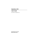
AlphaServer 800
User’s Guide
Order Number:
EK–ASV80–UG. B01
This manual is intended for the user of the DIGITAL AlphaServer
800 server system. It describes the operation of the system, explains
the use of the SRM and the AlphaBIOS consoles, gives procedures
for component replacements, and discusses troubleshooting.
Digital Equipment Corporation
Maynard, Massachusetts
Second Printing, November 1997. Revised.
Digital Equipment Corporation makes no representations that the use of its products in the
manner described in this publication will not infringe on existing or future patent rights, nor
do the descriptions contained in this publication imply the granting of licenses to make, use, or
sell equipment or software in accordance with the description.
The information in this document is subject to change without notice and should not be
construed as a commitment by Digital Equipment Corporation. Digital Equipment Corporation
assumes no responsibility for any errors that may appear in this document.
The software, if any, described in this document is furnished under a license and may be used
or copied only in accordance with the terms of such license. No responsibility is assumed for
the use or reliability of software or equipment that is not supplied by Digital Equipment
Corporation or its affiliated companies.
Copyright 1997 by Digital Equipment Corporation. All rights reserved.
The following are trademarks of Digital Equipment Corporation: AlphaServer, OpenVMS,
StorageWorks, VAX, and the DIGITAL logo.
The following are third-party trademarks: Lifestyle 28.8 DATA/FAX Modem is a trademark
of Motorola, Inc. UNIX is a registered trademark in the U.S. and other countries, licensed
exclusively through X/Open Company Ltd. U.S. Robotics and Sportster are registered
trademarks of U.S. Robotics. Windows NT is a trademark of Microsoft, Inc. All other
trademarks and registered trademarks are the property of their respective holders.
FCC Notice: This equipment has been tested and found to comply with the limits for a Class
B digital device, pursuant to Part 15 of FCC rules. These limits are designed to provide
reasonable protection against harmful interference in a residential installation.
This equipment generates, uses, and can radiate radio frequency energy and, if not installed
and used in accordance with the instructions, may cause harmful interference to radio
communications. However, there is no guarantee that interference will not occur in a
particular installation. If this equipment does cause harmful interference to radio and
television reception, which can be determined by turning the equipment off and on, the user is
encouraged to try to correct the interference by one or more of the following measures:
•
Reorient or relocate the receiving antenna
•
Increase the separation between the equipment and receiver
•
Connect the equipment into an outlet on a circuit different from that to which the receiver
is connected
•
Consult the dealer or an experienced radio/TV technician for help
This device complies with Part 15 of the FCC rules. Operation is subject to the following two
conditions: (1) this device may not cause harmful interference, and, (2) this device must
accept any interference received, including interference that may cause undesired operation.
Any changes or modifications made to this equipment may void the user’s authority to operate
this equipment.
If shielded cables have been supplied or specified, they must be used on the system in order to
maintain international regulatory compliance.
This Class B digital apparatus meets all the requirements of the Canadian InterferenceCausing Equipment Regulations.
Cet appareil numérique de la classe B respecte toutes les exigences du Réglement sur le
matériel broilleur du Canada.
——————————————————————————————————————
Contents
Preface ............................................................................................................ xiii
Chapter 1
1.1
1.2
1.3
1.4
1.5
1.6
1.7
1.8
1.9
1.10
System Architecture .................................................................................1-2
System Features .......................................................................................1-4
System Parts.............................................................................................1-6
Control Panel ...........................................................................................1-8
Rear Panel Connections ..........................................................................1-11
Storage Device LEDs .............................................................................1-13
Console ..................................................................................................1-15
System Options ......................................................................................1-16
System Specifications.............................................................................1-18
Acoustical Data ......................................................................................1-21
Chapter 2
2.1
2.2
2.3
2.4
2.5
2.6
2.7
2.8
Overview
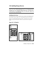
Installing a System into a Cabinet
Shipment Box...........................................................................................2-2
Preparing the System ................................................................................2-4
Marking the Installation Area in the Cabinet ............................................2-6
Preparing the Cabinet ...............................................................................2-8
Installing the System ..............................................................................2-10
Installing the Cable Management Bracket ..............................................2-12
Installing the Interlock Mechanism .........................................................2-14
Connecting the Cables ............................................................................2-16
v
Chapter 3
3.1
3.2
3.2.1
3.2.2
3.3
3.4
3.5
3.6
System Setup Overview............................................................................3-1
Selecting a System Location .....................................................................3-1
Environmental Conditions .................................................................3-2
Power Requirements..........................................................................3-3
Identifying Accessories ............................................................................3-4
Connecting the System .............................................................................3-5
Connecting to Network Hardware ............................................................3-6
Locking Your System...............................................................................3-7
Chapter 4
4.1
4.4
4.5
4.6
vi
Reconfiguring the System
AlphaBIOS Console Configuration Options .............................................5-2
SRM Console Configuration Commands ..................................................5-4
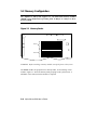
Memory Configuration .............................................................................5-8
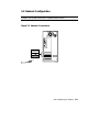
Network Configuration.............................................................................5-9
EISA and ISA Options ...........................................................................5-11
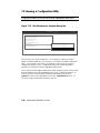
EISA Configuration Utility (ECU) .........................................................5-13
Configuring EISA and ISA Options........................................................5-14
Running ECU ..................................................................................5-15
Checking Required Environment Variable Settings .........................5-16
Verifying the System Configuration ................................................5-17
PCI Option Cards ...................................................................................5-18
Determining SCSI Storage Device IDs ...................................................5-19
Updating Firmware ................................................................................5-21
Updating Firmware Using the CD-ROM Drive ................................5-22
Updating Firmware Using the Network ...........................................5-23
Updating Firmware Using the Diskette Drive ..................................5-23
Chapter 6
6.1
6.2
6.2.1
6.2.2
6.2.3
6.2.4
Operating the System
Powering Up the System ..........................................................................4-2
Booting Windows NT.............................................................................4-10
Booting the Operating System for the First Time ....................................4-12
Powering Off the System ........................................................................4-15
Chapter 5
5.1
5.2
5.3
5.4
5.5
5.6
5.7
5.7.1
5.7.2
5.7.3
5.8
5.9
5.10
5.10.1
5.10.2
5.10.3
Installing the System
Using the SRM Console
Invoking the SRM Console.......................................................................6-1
SRM Console Tasks .................................................................................6-2
Displaying the System Configuration ................................................6-3
Booting the Operating System ...........................................................6-8
Testing the System ..........................................................................6-10
Forcing a System Crash Dump ........................................................6-12
6.2.5
6.2.6
6.2.7
6.2.8
6.2.9
6.2.10
6.3
6.3.1
6.3.2
6.3.3
6.3.4
6.4
6.5
Changing Environment Variables ....................................................6-13
Depositing and Examining Data ......................................................6-16
Reading a File .................................................................................6-19
Initializing the System .....................................................................6-20
Finding Help ...................................................................................6-22
Switching from SRM to the AlphaBIOS Console .............................6-23
SRM Console Security Features .............................................................6-24
The Set Secure Command ...............................................................6-24
The Set Password Command ...........................................................6-24
The Login Command .......................................................................6-25
The Clear Password Command ........................................................6-25
SRM Commands ....................................................................................6-26
Environment Variables ...........................................................................6-31
Chapter 7
7.1
7.2
7.3
7.3.1
7.3.2
7.3.3
7.3.4
7.3.5
7.3.6
7.3.7
7.4
7.5
7.5.1
7.5.2
7.6
7.7
7.8
7.9
7.9.1
7.9.2
7.10
7.11
7.12
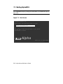
Starting AlphaBIOS .................................................................................7-2
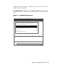
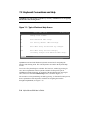
Keyboard Conventions and Help ..............................................................7-4
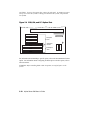
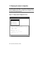
Displaying the System Configuration .......................................................7-6
System Board Configuration..............................................................7-8
Hard Disk Configuration .................................................................7-10
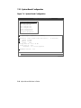
PCI Configuration ...........................................................................7-12
EISA Configuration .........................................................................7-15
SCSI Configuration .........................................................................7-16
Memory Configuration ....................................................................7-18
Integrated Peripherals ......................................................................7-19
Updating Firmware ................................................................................7-20
Setting Up the Hard Disk........................................................................7-22
Manually Creating and Dele ting Partitions ......................................7-26
Formatting a FAT Partition..............................................................7-28
Performing Setup Tasks..........................................................................7-30
Installing Windows NT ..........................................................................7-34
Running a Configuration Utility .............................................................7-36
Selecting the Version of Windows NT ....................................................7-38
Designating a Primary Operating System .........................................7-40
Primary Operating System and the Auto Start Option ......................7-42
Switching from AlphaBIOS to the SRM Console ...................................7-46
Setting Up Password Protection ..............................................................7-48
Running AlphaBIOS from a Serial Terminal ..........................................7-50
Chapter 8
8.1
8.2
8.3
Using the AlphaBIOS Console
Server Management
Operating the System Remotely ...............................................................8-2
RMC Functions ........................................................................................8-3
First Time Setup .......................................................................................8-5
vii
8.4
8.5
8.6
Resetting the RMC to Factory Defaults ....................................................8-9
Remote Management Console Commands ..............................................8-10
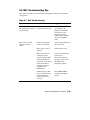
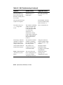
RMC Troubleshooting Tips ....................................................................8-21
Chapter 9
9.1
9.2
9.3
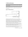
SCSI Bus Controller .................................................................................9-1
Configuration ...........................................................................................9-1
External SCSI Expansion .........................................................................9-4
Chapter 10
10.1
10.2
10.3
10.3.1
10.3.2
10.4
10.4.1
10.4.2
10.4.3
10.5
viii
Installing Components
Preparing to Install or Remove Components ...........................................10-2
Removing and Installing Memory DIMMs .............................................10-6
Removing and Installing Option Cards ...................................................10-9
Installing and Removing an Option Card .......................................10-10
Testing an Option Card Installation ...............................................10-13
Installing Storage Devices ....................................................................10-15
Installing and Removing a Hard Drive ...........................................10-16
Installing a 5.25-Inch Device .........................................................10-18
Installing SCSI Controller Options ................................................10-21
Removing/Replacing Other Options .....................................................10-26
Chapter 11
11.1
11.2
11.2.1
11.2.2
11.2.3
11.2.4
11.3
11.4
11.5
11.6
11.7
11.8
11.9
11.10
11.11
11.12
11.13
11.14
Using the Hard Disks
Troubleshooting
Troubleshooting Overview .....................................................................11-2
System Diagnostics ................................................................................11-4
Interpreting Error Beep Codes .........................................................11-4
Reading the Console Event Log .......................................................11-6
The test Command ..........................................................................11-6
The show_status Command .............................................................11-7
Power Problems .....................................................................................11-8
Console Problems...................................................................................11-9
Boot Problems......................................................................................11-10
Problems Detected by the Operating System ........................................11-12
Storage Problems .................................................................................11-13
Option Card Problems ..........................................................................11-15
Monitor and Terminal Problems ...........................................................11-18
Keyboard and Mouse Problems ............................................................11-20
Printer Problems...................................................................................11-22
Overheating Problems ..........................................................................11-22
Using the Fail-Safe Loader ...................................................................11-23
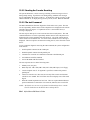
Hard Disk Troubleshooting Suggestions ...............................................11-25
Examples
4–1
4–2
4–3
5–1
5–2
5–3
5–4
5–5
5–6
6–1
6–2
6–3
6–4
6–5
6–6
6–7
6–8
6–9
6–10
6–11
6–12
6–13
6–14
6–15
6–16
10-1
11–1
DIGITAL UNIX and OpenVMS Power-Up Display .................................4-3
Booting DIGITAL UNIX from a Local Device ........................................4-6
Booting OpenVMS...................................................................................4-8
System Configuration Display ..................................................................5-2
Show Config Command ...........................................................................5-4
Show Device Command ...........................................................................5-6
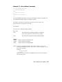
Show Memory Command .........................................................................5-6
Set and Show Commands .........................................................................5-7
Determining Device IDs .........................................................................5-20
Show Config Command ...........................................................................6-3
Show Device Command ...........................................................................6-4
Show Memory Command .........................................................................6-6
Show PAL Command...............................................................................6-7
Show Version Command ..........................................................................6-7
Boot Command ........................................................................................6-8
Test Command .......................................................................................6-10
Crash Command.....................................................................................6-12
Set envar and Show envar Commands....................................................6-13
Edit Command .......................................................................................6-15
Deposit Command..................................................................................6-16
Examine Command ................................................................................6-16
More Command .....................................................................................6-19
Initialize Command ................................................................................6-20
Help (or Man) Command ......................................................................6-22
Switching to the AlphaBIOS Console .....................................................6-23
The show config Command Display .....................................................10-14
Test Command .......................................................................................11-7
Figures
1-1
1-2
1-3
1-4
1-5
1-6
1-7
2-1
2-2
2-3
2-4
2-5
Block Diagram of the AlphaServer 800 Server System .............................1-2
AlphaServer 800 System Parts..................................................................1-6
Control Panel ...........................................................................................1-8
Rear Panel Connections ..........................................................................1-11
Hard Disk Drive LEDs ...........................................................................1-13
Floppy Drive Activity LED ....................................................................1-14
CD-ROM Drive Activity LED................................................................1-14
Unpacking the Rackmount System ...........................................................2-2
Preparing the System for Rackmount ........................................................2-4
Rackmount Installation Area ....................................................................2-6
Preparing the Cabinet for Rackmount .......................................................2-8
Installing the System ..............................................................................2-10
ix
2-6
2-7
2-8
3-1
3-2
3-3
3-4
3-5
3-6
4-1
4-2
5-1
5-2
5-3
5-4
5-5
5-6
6-1
7–1
7–2
7–3
7–4
7–5
7–6
7–7
7–8
7–9
7–10
7–11
7–12
7–13
7–14
7–15
7–16
7–17
7–18
7–19
7–20
7–21
7–22
7–23
7-24
7–25
7–26
x
Installing the Cable Management Bracket ..............................................2-12
Installing the Interlock Mechanism .........................................................2-14
Cable Loop at the Rear of the System .....................................................2-16
System Dimensions and Service Area .......................................................3-2
Power Supply Requirements .....................................................................3-3
System Accessories ..................................................................................3-4
System Connections .................................................................................3-5
Network Connections ...............................................................................3-6
System Lock and Key...............................................................................3-7
Windows NT Power-Up Display ..............................................................4-2
AlphaBIOS Boot Screen.........................................................................4-10
Memory Banks .........................................................................................5-8
Network Connections ...............................................................................5-9
EISA and ISA Cards...............................................................................5-11
EISA, ISA, and PCI Option Slots ...........................................................5-12
Run ECU from Floppy Dialog Box.........................................................5-15
PCI Option Card.....................................................................................5-18
Device Naming Convention .....................................................................6-5
Boot Screen..............................................................................................7-2
AlphaBIOS Setup Screen .........................................................................7-3
Typical First-Level Help Screen ...............................................................7-4
Second-Level Help Screen .......................................................................7-5
Display System Configuration Screen ......................................................7-6
System Board Configuration ....................................................................7-8
Hard Disk Configuration ........................................................................7-10
PCI Configuration ..................................................................................7-12
Advanced PCI Information .....................................................................7-14
EISA Configuration................................................................................7-15
SCSI Configuration ................................................................................7-16
Memory Configuration ...........................................................................7-18
Integrated Peripherals .............................................................................7-19
Updating Firmware ................................................................................7-20
Hard Disk Setup Screen..........................................................................7-22
Create New Partition Dialog Box ...........................................................7-26
Delete Partition Dialog Box ...................................................................7-27
Formatting a FAT Partition ....................................................................7-28
Standard Formatting ...............................................................................7-29
Standard CMOS Setup Screen ................................................................7-30
Advanced CMOS Setup Screen ..............................................................7-32
Installing Windows NT ..........................................................................7-34
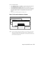
Run Maintenance Program Dialog Box ..................................................7-36
Execute Run Maintenance Program ........................................................7-37
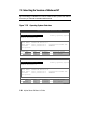
Operating System Selections ..................................................................7-38
Primary Operating System......................................................................7-40
7–27
7–28
7–29
8-1
9-1
9-2
10-1
10-2
10-3
10-4
10-5
10-6
10-7
10-8
10-9
10-10
10-11
10-12
10-13
10-14
10-15
11–1
Operating System Selection Setup ..........................................................7-42
Switching to the SRM Console ...............................................................7-46
Advanced CMOS Setup Menu................................................................7-48
Remote Management Console Block Diagram .........................................8-2
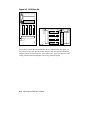
SCSI Drive IDs ........................................................................................9-2
RAID Cable for Hard Disk Drives ............................................................9-3
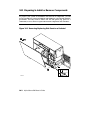
Removing/Replacing Side Panel on a Pedestal .......................................10-2
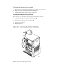
Attaching the Antistatic Wrist Strap .......................................................10-4
Removing/Replacing Top Cover on a Rackmount ..................................10-5
Memory Connector Layout.....................................................................10-6
Removing a Memory DIMM ..................................................................10-7
Installing a Memory DIMM ...................................................................10-8
PCI, EISA, and ISA Option Cards ........................................................10-10
Installing or Removing an Option Card ................................................10-11
SCSI Bus IDs .......................................................................................10-15
Installing a Hard Drive .........................................................................10-16
Installing a 5.25-Inch Device ................................................................10-19
Continuing Installation of a 5.25-Inch Device ......................................10-20
RAID/SCSI Cable for Internal Disk Drive Backplane ...........................10-22
Wide SCSI Cable for Breakouts at Rear of Enclosure ...........................10-23
Wide SCSI Dual Connector Cable for Std Bulkhead Connector ............10-24
J1 Jumper on the CPU Card (Normal Position) .....................................11-24
Tables
1
1-1
1-2
1-3
3–1
3–2
5–1
5–2
5–3
6–1
6–2
6–3
6–4
6–5
7-1
8-1
8-2
10–1
11–1
AlphaServer 800 Documentation...............................................................20
System Status Indicated by the Control Panel LEDs ...............................1-10
System Specifications.............................................................................1-18
AlphaServer 800 Acoustical Data ...........................................................1-21
Environmental Conditions ........................................................................3-2
System Accessories ..................................................................................3-5
Resetting Environment Variables ...........................................................5-16
Hard Drive SCSI ID Numbers ................................................................5-19
Determining Available SCSI IDs (SRM Console) ...................................5-20
Summary of SRM Console Commands...................................................6-26
Notation Formats for SRM Console Commands .....................................6-28
Special Characters for SRM Console ......................................................6-29
Environment Variable Summary ............................................................6-31
Settings for boot_osflags Bootflags (OpenVMS) ....................................6-35
Serial Terminal Key Commands for AlphaBIOS and ECU .....................7-50
Dial and Alert String Elements .................................................................8-6
RMC Troubleshooting ............................................................................8-21
Testing with the show config Display ...................................................10-13
Determining Where to Look ...................................................................11-3
xi
11–2
11–3
11–4
11–5
11–6
11–7
11–8
11–9
11–10
11–11
11–12
xii
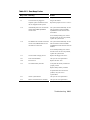
Error Beep Codes ...................................................................................11-5
Troubleshooting Power Problems ...........................................................11-8
Troubleshooting Console Problems ........................................................11-9
Troubleshooting Boot Problems ...........................................................11-10
Problems Detected by the Operat ing System ........................................11-12
Troubleshooting Mass Storage Problems ..............................................11-13
Troubleshooting EISA/ISA Bus Problems ............................................11-16
Troubleshooting PCI Bus Problems ......................................................11-17
Troubleshooting Monitor and Terminal Problems .................................11-18
Troubleshooting Keyboard and Mouse Problems ..................................11-20
Troubleshooting the Hard Disk .............................................................11-25
Preface
Intended Audience
This manual is intended for the operator of the AlphaServer 800 system.
Document Structure
This manual uses a structured documentation design. Topics are organized into small
sections for efficient online and printed reference. Each topic begins with an
abstract. You can quickly gain a comprehensive overview by reading only the
abstracts. Next is an illustration or example, which also provides quick reference.
Last in the structure are descriptive text and syntax definitions.
The material is presented in 11 chapters.
•
Chapter 1, Overview, describes the features and the major parts of the system.
•
Chapter 2, Installing a System into a Cabinet, explains how to install a unit
in a system cabinet.
•
Chapter 3, Installing the System, explains how to set up and interconnect the
hardware components of the system.
•
Chapter 4, Operating the System, tells how to power the system on and off,
discusses booting of the three operating systems, and operating the system
remotely.
•
Chapter 5, Reconfiguring the System, tells how to use console commands to
reconfigure the system and describes how to run configuration utilities.
•
Chapter 6, Using the SRM Console, tells how to invoke the SRM console and
describes how to perform certain SRM console tasks.
•
Chapter 7, Using the AlphaBIOS Console, tells how to start AlphaBIOS and
perform common system management tasks.
•
Chapter 8, Server Management Console, describes the integrated server
management console and explains how to operate the system remotely.
xiii
•
Chapter 9, Using the Hard Disks, describes the operation of the hard disks.
•
Chapter 10, Installing Components, discusses how to remove and install
system components and add new options.
•
Chapter 11, Troubleshooting, provides basic troubleshooting information for
the system.
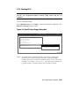
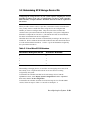
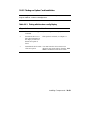
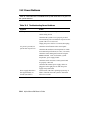
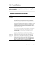
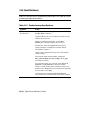
Documentation Titles
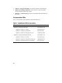
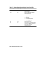
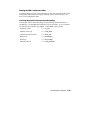
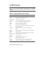
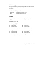
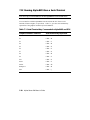
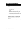
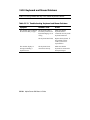
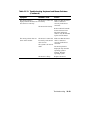
Table 1 lists the books in the AlphaServer 800 documentation set.
Table 1 AlphaServer 800 Documentation
Title
Order Number
AlphaServer 800 System Info Kit
QZ–00XAA–GW
AlphaServer 800 User’s Guide
EK–ASV80–UG
AlphaServer 800 Basic Installation
EK–ASV80–IG
AlphaServer 800 Local Language Doc CD
AG–R5DUA–BE
AlphaServer 800 System Maintenance Kit
QZ–00XAB –GZ
AlphaServer 800 Service Guide
EK–ASV80–SG
AlphaServer 800 Service Information (help file)
AK–R2MAA–CA
AlphaServer 800 Illustrated Parts Breakdown
EK–ASV80–IP
xiv
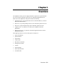
Chapter 1
Overview
The AlphaServer 800 system is a high-performance, uniprocessor system intended
for use as a local area network (LAN) server or commercial applications server.
Ideal uses for the AlphaServer 800 system include the following:
•
Application server−To run applications such as relational databases, electronic
mail, and communications
•
Print server−To provide printing resources to PCs and other systems in a LAN
•
File server−To provide disk storage to PCs and other systems in a LAN
•
Compute server−To enable PCs to remotely run computation-intensive
applications
•
Replicated site server −To operate in commercial applications due to remote
management features
This chapter provides an overview of the system. Sections are:
•
System Architecture
•
System Features
•
System Parts
•
Control Panel
•
Rear Panel Connections
•
Storage Device LEDs
•
Console
•
System Options
•
System Specifications
•
Acoustical Data
Overview 1-1
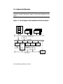
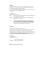
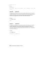
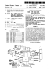
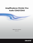
1.1 System Architecture
The AlphaServer 800 system is a low-end server that offers PCI and EISA bus
options on a single system board. Figure 1-1 shows the architecture of the
system.
Figure 1-1 Block Diagram of the AlphaServer 800 Server System
CPU
Cache
Xbar
Switch
Memory
Memory
Memory Bus
VGA
PCI Bus
SCSI
64-Bit
PCI
or
32-Bit
PCI
32-Bit
PCI
SCSI Bus
EISA
EISA
EISA
EISA Bus
32-Bit
PCI
PCI/EISA
Bridge
PK-0700E-97
1-2 AlphaServer 800 User’s Guide
The AlphaServer 800 system is housed in an enclosure containing the motherboard,
CPU daughter card, other logic modules, and power supply with internal fans. The
enclosure allows for up to four internal mass-storage devices, with up to four
removable media devices, one of which is a 3.5-inch floppy drive. The control panel
includes Halt, Reset, and On/Off buttons. The system can be used as a deskside
pedestal in the vertical position, or, with the addition of brackets, may be mounted in
the horizontal position in a standard 19-inch rack.
All memory and I/O components are on a single system board that contains the
memory subsystem, the PCI bus, the EISA I/O bus, the integrated system I/O
controllers, and option slots for PCI-based and EISA-based option cards. A server
management corner on the system board serves to monitor/control the system
remotely.
The CPU daughter card interfaces to the motherboard with a 600-pin connector.
It is based on a 21164 microprocessor that is a superscalar, super-pipelined
implementation of the Alpha architecture and runs at an optimized price/
performance speed of 300 to 500 MHz. The chip contains two 8-Kbyte, directmapped primary caches and a 96-Kbyte, 3-way set-associative secondary cache. The
CPU card uses a 2-Mbyte, direct-mapped, writeback B-cache. The B-cache is 16
bytes wide with a block size of 64 bytes.
Overview 1-3
1.2 System Features
The system offers a number of features that ensure high performance,
expandability, enhanced reliability, high availability, remote server
management, and improved security.
High Performance
•
64-bit Alpha architecture
Provides significantly better performance
than 32-bit architecture.
•
Microprocessor
Fast microprocessor for enhanced system
performance.
•
2-Mbyte third-level cache
Reduces significantly memory
transaction times.
•
Integrated fast wide SCSI controller
Supports tape, CD-ROM, and hard disk
devices without use of an expansion slot.
•
Integrated PCI graphics
controller
Makes an additional expansion slot
available for other applications.
•
Warm-swapping of 3.5-inch fullheight devices
Allows replacement of disk drives while
the system continues to operate.
•
Ultra SCSI-ready backplane
Provides high-performance drive
technology.
Operating Systems
DIGITAL UNIX
OpenVMS
Windows NT
Flexible Packaging
Single enclosure available as freestanding pedestal or rack-mountable box.
System Expansion
•
Flexible memory architecture
1-4 AlphaServer 800 User’s Guide
Provides a 256-bit memory data path.
Allows incremental memory expansion
from 32 Mbytes to 2 Gbytes.
•
Three 32-bit PCI slots, one shared
64-bit PCI/EISA slot, and two
dedicated EISA slots
Accommodates industry-standard option
cards such as Ethernet, FDDI, SCSI, and
modems.
•
Capacity for eight internal storage
devices
A modular storage system accommodates up to four 3.5-inch full-height
SCSI devices. The system also supports
up to three 5.25-inch half-height devices
(CD-ROM or tape) and one 3.5-inch
high-density diskette drive.
•
External ports
Two serial ports and one parallel port
support external options such as printer,
modem, or local terminal.
Reliability/Availability
•
Error correction code (ECC)
Allows recovery from most cache and
memory errors.
•
Internal sensors
Monitor and detect internal system
temperature, fan failure, power supply,
status, system watchdog timer.
•
Variable fan speed
Adjusts fan speed according to system
temperature.
Server Management
•
System diagnostics
Allows local and remote diagnosis of
system failures.
•
Hardware configuration
Allows local and remote system
configuration.
•
Firmware utility
Enables loading and verification of latest
firmware versions.
•
Remote management console
Enables monitoring of system conditions
and manipulating of the control panel
from a remote terminal. Provides
operator paging on “alert” conditions.
System Security
•
Key lock (pedestal only)
Limits access to system components.
•
Security hole (on rear of system
unit)
Allows system to be secured in place.
Overview 1-5
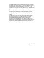
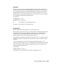
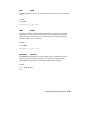
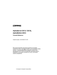
1.3 System Parts
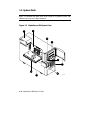
Figure 1-2 identifies the main parts of the system in a pedestal version. The
enclosure has a top cover and a side panel.
Figure 1-2 AlphaServer 800 System Parts
7
9
2
3
5
4
8
6
1
1-6 AlphaServer 800 User’s Guide
IP00110B
The main components of an AlphaServer 800 system are:
²
³
´
µ
·
¸
¹
º
Removable side cover of system enclosure
Floppy diskette drive
Removable media drives
Lower and upper doors
Control panel
Hard disk drives
System board
CPU daughter card
Power supply
Overview 1-7
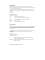
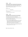
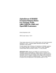
1.4 Control Panel
The control panel provides system controls and status indicators on the front of
the AlphaServer 800 enclosure.
Figure 1-3 Control Panel
1
2
4
3
IP00039-97
1-8 AlphaServer 800 User’s Guide
The control panel consists of three pushbutton controls and two LED indicators:
•
Power On/Off button
•
Halt button
•
Reset button
•
Green Power OK indicator
•
Amber Halt indicator
The functions provided by these pushbutton conrols and indicators are discussed
next.
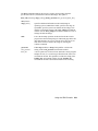
²
³
´
µ
Power On/Off — Powers the system on or off. When the LED is lit, the
power is on. Turning the power off and then on clears the shutdown condition
and attempts to power the system back on. Failure conditions that prevent
the system from powering on can be determined from the remote
management console using the Status command. The remote management
console is powered separately from the rest of the system and is functional as
long as AC power is present.
The Power On/Off button overrides the remote management console. Thus, a
system that has been powered off or halted remotely can be restarted from the
control panel without the need to access the remote management console.
This becomes important in systems without a local character cell terminal for
a system console where no local access to the remote management console is
possible.
Halt button — When the button is in the In position, a single halt interrupt is
provided to the CPU. On OpenVMS and DIGITAL UNIX this halt interrupt
causes a return to the SRM console. Also, when the Halt button is In at
power-up, the system comes up with the SRM console.
Reset button — A momentary contact switch that initializes the system.
Indicator lights — The control panel has two lights for indicating the basic
system state. One is a green Power OK indicator and the other is an amber
Halt indicator. The system state is described in Table 1-1.
Overview 1-9
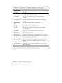
Table 1-1 System Status Indicated by the Control Panel LEDs
Green LED
Yellow LED
Status
Off
Off
System is powered off or no AC
power is present.
Off
On
Power is enabled, but system has
been powered off by:
•
Remote console command
•
System software
•
Fan failure
•
Overtemperature failure
•
Power supply failure
On
Off
System is powered on.
On
On
System power is on and Halt button is
pressed in or a halt in command has
been issued at the remote
management console.
1-10 AlphaServer 800 User’s Guide
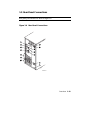
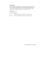
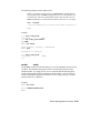
1.5 Rear Panel Connections
Rear panel ports and slots are shown in Figure 1-4.
Figure 1-4 Rear Panel Connections
1
2
5
6
7
10
9
8
1
4
2
3
3
4
IP00030A-97
Overview 1-11
The following list describes the rear panel connections:
²
³
´
µ
·
¸
¹
º
»
¨
©
ª
«
Three 32-bit PCI slots — For option cards for high-performance network, video,
or disk controllers
One 64-bit slot — For either a PCI card or an EISA card
Two EISA slots — For option cards for network, video, sound, or disk
controllers
Parallel port — To parallel device such as a printer
Serial port (COM2) — Extra port to modem or any serial device
Mouse port — To PS/2-compatible mouse
VGA port — To VGA monitor
Keyboard port — To PS/2-compatible keyboard
Remote console modem port — Dedicated 9-pin port for connection to remote
management console and system COM1 through modem. Provides full
modem control.
Power inlet — To power outlet
Serial port/terminal port (COM1) — To console terminal. This is an M MJ
with data leads only.
AC switch 115V/220VKey — Should be pointing to the correct input AC
voltage.
SCSI breakouts — To SCSI devices
Security hole — To secure the system
1-12 AlphaServer 800 User’s Guide
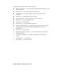
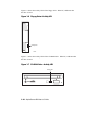
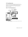
1.6 Storage Device LEDs
Storage device LEDs indicate the status of the device. Figure 1-5 shows the hard
disk drive LEDs.
Figure 1-5 Hard Disk Drive LEDs
DiskPresent
Fault
Activity
IP00080
LED
Function
Activity (green)
When lit indicates disk activity.
Fault (amber)
Reserved for future use. Has no function at
product introduction.
Disk Present (green)
When lit, indicates that a drive is installed in that
slot.
Overview 1-13
Figure 1-6 shows the Activity LED of the floppy drive. When lit, it indicates that
the drive is active.
Figure 1-6 Floppy Drive Activity LED
Activity LED
IP00081-97
Figure 1-7 shows the Activity LED of the CD-ROM drive. When lit, it indicates that
the drive is active.
Figure 1-7 CD-ROM Drive Activity LED
Activity LED
IP00082-97
1-14 AlphaServer 800 User’s Guide
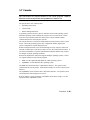
1.7 Console
The system offers two separate interfaces to the console program: SRM for
DIGITAL UNIX and OpenVMS; and AlphaBIOS for Windows NT.
The system runs in one of three modes:
•
Operating system mode
•
Console mode
•
Remote management mode
In operating system mode, the system is under the control of the operating system.
When the operating system is halted, the system reverts to console mode. In this
mode, the system operates under the control of the console firmware and the
commands entered or selected by the operator.
The console firmware is located in a flash ROM (read-only memory) on the system
board. It boots the operating system, runs configuration utilities, displays the
system configuration, and runs diagnostic tests.
Remote management mode can be entered through an escape sequence at the local
terminal or modem port. This allows remote access to the control panel functions. It
also allows maintenance of system environmental conditions and the setup of alerts
for changes in certain operating conditions.
Because the AlphaServer 800 system supports multiple operating systems, it offers
two separate interfaces to the console program:
•
SRM—For the OpenVMS and DIGITAL UNIX operating systems
•
AlphaBIOS—For the Windows NT operating system
The SRM console firmware has a command-line interface. The operator enters
commands at the console prompt. Environment variables are used to control system
behavior.
The AlphaBIOS console firmware has a menu-based interface. The operator selects
an item from the menu displayed on a screen.
Refer to Chapter 6 for the operations of the SRM console and to Chapter 7 for the
operations of the AlphaBIOS console.
Overview 1-15
1.8 System Options
The AlphaServer 800 system supports storage options, PCI/EISA/ISA options,
and memory options.
Internal Options
The AlphaServer 800 system supports the following types of internal options:
•
Storage
•
PCI/EISA/ISA
•
Memory
Storage devices include:
•
One diskette drive
•
Up to three removable-media storage devices, one of which is typically a CDROM drive
•
Up to four 3.5-inch full-height SCSI hard disks
The system supports PCI/EISA/ISA options, including those for:
•
SCSI storage expansion
•
Networking and communication
•
Graphics
The memory cards are inserted on eight 168-pin, 3.3 volt DIMM sockets on the
system board. Memory is configured in banksets of four to form the databus width
of 256 data bits and 32 bits of ECC. Possible memory capacities range from 32
Mbytes (using a single bankset of 1Mx72 DIMMs) to 2 Gbytes (using 32Mx72
DIMMs). Each DIMM in a bankset must be of the same capacity. Each bankset is
separately configurable as to base address and size.
1-16 AlphaServer 800 User’s Guide
External Options
Other options that can be added to the system externally include the following:
•
Monitor or terminal
•
Expansion boxes
•
Printers
•
RAID controller
•
Uninterruptible power supply (UPS)
•
Modem
Ordering Options
The list of supported options is subject to change. Contact your sales representative
for information on the current list of supported options and for information on
ordering. If you are an Internet participant, you can obtain information related to the
AlphaServer 800 system through the DIGITAL FTP archive:
ftp://ftp.digital.com/pub/Digital/Alpha/systems/as800/
The WWW site for technical documentation and supply lists is:
http://www.digital.com/alphaserver/tech_docs/alphasrv800/
Users of the Windows NT operating system can access the Microsoft hardware
compatibility list (HCL) of officially supported devices through:
http://www.windowsnt.digital.com/support/hcl/hcl.htm
Overview 1-17
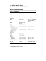
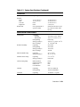
1.9 System Specifications
Table 1-2 gives the AlphaServer 800 system specifications.
Table 1-2 System Specifications
Physical Characteristics
Pedestal
Height
Width
Depth
Weight
45 cm (17.7 in.)
22.6 cm (8.9 in.)
65.8 cm (25.9 in.)
Typical: 24.5 kg (54 lb)
Max: 28 kg (62 lb)
Rackmount
Height
22 cm (8.6 in.)
Width
Standard EIA 310D
(RETMA)
63.8 cm (25.1 in.)
Depth
Weight
1. When lifting
2. Total added to cabinet
(includes brackets,
slides, and cables)
Fits 8 ¾ in. [5U] standard
EIA 310D (RETMA)
cabinets
Typical: 24.5 kg (54 lb)
Max: 28 kg (62 lb)
Typical: 30 kg (66 lb)
Max: 35 kg (77 lb)
Shipping Container
(Pedestal and
Rackmount)
Height
Width
Depth
Weight
Pedestal
Rackmount
47 cm (18.5 in.)
60 cm (23.6 in.)
77.5 cm (30.5 in.)
Max Heat Dissipation
380 Watts, 1297 Btu/hr
Acoustics
Operating
Typical: 33 kg (73 lb)
Typical: 39 kg (85 lb)
1-18 AlphaServer 800 User’s Guide
Max: 37 kg (82 lb)
Max: 44 kg (96 lb)
LNPEc (BELs) 6.0 max
per ISO 7779
Table 1-2 System Specifications (Continued)
Clearances
Pedestal
Front
Rear
Left side
Right side
Rackmount
Operating
Service
75 cm (29.5 in.)
15 cm (5.9 in.)
None
None
See requirements of
specific cabinet
75 cm (29.5 in.)
75 cm (29.5 in.)
75 cm (29.5 in.)
5 cm (2 in.)
Slides forward 68.6 cm (27
in.), then accessible from
the top
Environmental Characteristics
Temperature
Operating
Pedestal
Rackmount
Nonoperating
Storage (60 days)
Rate of change
10 to 40 C (50 to 104 F)
o
o
10 to 35 C (50 to 95 F)
Not tested
o
o
-40 to 66 C (-40 to 151 F)
o
o
11 C/hr (20 F/hr
Relative Humidity
Operating
Nonoperating
Storage (60 days)
Rate of change
20 to 80%
20 to 80%
10 to 95%
20%/hr
Max Wet Bulb Temp
Operating
Storage (60 days)
28 C (82 F)
o
o
46 C (115 F)
Min Dew Point Temp
Operating
Storage (60 days)
2 C (36 F)
Not tested
Airflow and Quality
Intake location
Exhaust location
Particle size
Concentration
Front
Rear
N/A
N/A
Altitude
Operating
Nonoperating
3037 m (10,000 ft)
12190 m (40,000 ft)
Vibration
Operating
10-500 Hz .1 G peak
o
o
o
o
o
0o
Overview 1-19
Table 1-2 System Specifications (Continued)
Electrical Characteristics
Nominal AC Voltage
Voltage Range (Vac temporary condition)
Power Supply Phase
Nominal Frequency
Frequency Range
RMS Current (steady state) at Nominal Voltage
Max Power Consumption
1-20 AlphaServer 800 User’s Guide
100 to 120 Vac/220 to 240 Vac
88 to 132 Vac/176 to 264 Vac
Single/Single
60 Hz/50 Hz
57-63 Hz/47-53 Hz
7.0 amps/3.0 amps
380 Watts
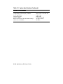
1.10 Acoustical Data
Table 1-3 gives the noise declaration for an AlphaServer 800 system with diskless,
1-Gbyte or 2-Gbyte RZ28M configurations.
Table 1-3 AlphaServer 800 Acoustical Data
Acoustics — Declared Values per ISO 9296 and ISO 7779
Sound Power Level
Sound Pressure Level
L wAd, B
L pAm, dBA
(bystander positions)
Product
Idle
Operate
Idle
Operate
PB80A-A9 (AlphaServer 800)
[with 0 x HDD]
PB80A-A9 + RZ26N
PB80A-A9 + RZ28M
5.7
5.7
39
39
5.7
5.7
6.0
6.0
39
39
42
42
Current values for specific configurations are available from DIGITAL representatives. 1 B = 10 dBA.
Schallemissionswerte — Werteangaben nach ISO 9296 und ISO 7779/DIN
EN27779
Schalleistungspegel
Schalldruckpegel
LwAd, B
LpAm, dBA
(Zuschauerpositionen)
Gerät
Leerlauf
Betrieb
Leerlauf
Betrieb
PB80A-A9 (AlphaServer 800)
[mit 0 x HDD]
PB80A-A9 + RZ26N
PB80A-A9 + RZ28M
5.7
5.7
39
39
5.7
5.7
6.0
6.0
39
39
42
42
Aktuelle Werte für speziele Ausrüstungsstufen sind uber die Digital Equipment Vertretungen erhältelich.
1 B = 10 dBA.
Overview 1-21
Chapter 2
Installing a System into a Cabinet
This chapter gives installation procedures for a rackmount system. Sections are:
•
Shipment Box
•
Preparing the System
•
Marking the Installation Area in the Cabinet
•
Preparing the Cabinet
•
Installing the System
•
Installing the Cable Management Bracket
•
Installing the Interlock Mechanism
•
Connecting the Cables
CAUTION: Because of heavy lifting and maneuvering involved, two people are
needed to handle the installation. A single person should NOT attempt to install the
system.
Installing a System into a Cabinet 2-1
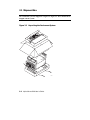
2.1 Shipment Box
The rackmount system is shipped in a single box. Figure 2-1 shows the hardware
shipped with the system.
Figure 2-1 Unpacking the Rackmount System
IP00058
2-2
AlphaServer 800 User’s Guide
The rackmount system is shipped in a single box that contains the following items:
•
The AlphaServer 800 system already assembled
•
Front bezel assembly—P/N 70-33178-01
•
Poly bag containing mounting hardware
The mounting hardware consists of the following items:
Mounting Hardware
Part Number
Four slide brackets
74-51454-01
Two front mounting brackets
74-51572-01
One actuator trip bracket
74-51571-01
Four nut bars
74-51531-01
Six M4 x 6 mm pan head screws
N/A
Eleven M4 x 10 mm pan head screws
90-40005-06
Sixteen 10-32 X 0.5 truss head screws
90-00063-39
Six 10-32 U-nuts
90-07786-00
Four M4 kepnuts
90-40203-02
In addition, the shipping box includes the following items to be secured to the
cabinet or mounted on the system:
•
One front bezel
•
Two chassis slides
•
One cable management bracket
•
One actuator stabilizer bracket
•
One actuator latch
You need to do preinstallation work to prepare the system for mounting into the
cabinet.
Installing a System into a Cabinet 2-3
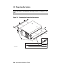
2.2 Preparing the System
Prepare the system as described in the following procedure. Use Figure 2-2 as a
guide.
Figure 2-2 Preparing the System for Rackmount
2
3
1
IP00055B-97
2-4
AlphaServer 800 User’s Guide
Prepare the system as follows:
CAUTION: The chassis slides are lightly greased. Handle them carefully to avoid
soiling of clothing.
² to each side of the system using two M4 x 10
1.
Attach a front mounting bracket
mm screws per bracket.
2.
Tighten an M4 x 10 mm screw at the back end of the right side of the system.
3.
Pull the narrow segment
of the chassis slide out of a chassis slide and detach
and continuing to pull.
it completely by pressing down the retainer spring
Position the chassis slide track so that the end of the chassis slide with three
holes will stick out past the system. Secure the chassis slide track to the
system with three M4 x 6 mm screws.
´
³
µ
·
Repeat the step for the other chassis slide.
The system is now ready for installation.
Installing a System into a Cabinet 2-5
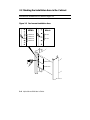
2.3 Marking the Installation Area in the Cabinet
Determine the installation area as shown in Figure 2-3.
Figure 2-3 Rackmount Installation Area
NEMA
Metric
0.500 inch
25 mm
0.625 inch
25 mm
0.625 inch
0.500 inch
4.375 inch
4.375 inch
IP00064
2-6
AlphaServer 800 User’s Guide
The installation of the rackmount system requires 8.75 inches (5U) of vertical height
in the cabinet.
1.
Mark the midpoint hole on the vertical rail as shown in Figure 2-3. The midpoint
hole must be selected so that the holes immediately above and immediately
below are equidistant (.625 inches).
2.
Mark the corresponding hole on the other three rails.
Installing a System into a Cabinet 2-7
2.4 Preparing the Cabinet
Prepare the cabinet as described in the following procedure. Use Figure 2-4 as a
guide.
Figure 2-4 Preparing the Cabinet for Rackmount
3
4
2
5
1
8
6
7
9
IP00062B
2-8
AlphaServer 800 User’s Guide
Prepare the cabinet as follows:
1.
Attach slide brackets to the cabinet rails.
²
³
to each of the four vertical rails of the cabinet
using
Attach slide bracket
per slide bracket. The slide bracket installs
two 10-32 screws and one nut bar
behind the vertical rail of the cabinet and the nut bar installs behind the slide
bracket, as shown in Figure 2-4.
´
NOTE: The chassis slide bracket has two dissimilar ends. Flip the bracket
and use the other end for larger hole spacing of 25 mm.
µ
Locate the middle hole of the slide bracket and nut bar to the midpoint hole
marked on the vertical rail of the cabinet in Section 2.3. Tighten 10-32 screws
in the hole above and below the marked midpoint hole, leaving the midpoint
hole empty.
Attach the other three brackets to the rails in the same manner.
2.
Attach chassis slides to the slide brackets.
Place the chassis slide into two brackets. Pull the inner slide out until the
forwardmost hole in the stationary segment of the chassis slide is exposed.
Aligns this hole with the forwardmost hole in the chassis slide bracket . Note
that this happens when the stationary segment, the front of the slide bracket, and
the mounting surface of the vertical rail are vertically aligned. Fasten one M4 x
through a
10 mm screw and kepnut . Place another M4 x 10 mm screw
hole in the stationary segment of the chassis slide and the slot in the rear
mounted slide bracket, and attach with a kepnut.
·
¸
3.
¹
º
Repeat the procedure for the other slide
The cabinet is now ready for the installation of the system.
Installing a System into a Cabinet 2-9
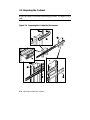
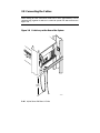
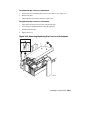
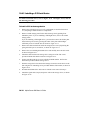
2.5 Installing the System
Install the system as described in the following procedure. Use Figure 2-5 as a
guide.
Figure 2-5 Installing the System
1
2
3
IP00065C-97
2-10
AlphaServer 800 User’s Guide
Observe the following precautions before you begin to install the system into the
cabinet:
CAUTION:
1. Make sure that all devices are pushed into the cabinet and no device is
disengaged.
2. Activate the stabilizer foot of the cabinet, if the cabinet is so equipped, or
provide other means to stabilize the cabinet before installation of the system.
3. The system is heavy. It should be lifted by two persons.
1.
Lift the system, align the narrow segment of the chassis slides attached to the
system with the chassis slides attached to the cabinet . Slide the system into
the cabinet. Depress the retainer spring on both slides to slide the system
completely into the cabinet. Tighten the system to the chassis slides with two
10-32 screws one on each side.
²
³
2.
Align the front bezel
´ with the front of the system and snap it in place.
Installing a System into a Cabinet 2-11
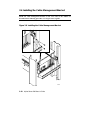
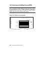
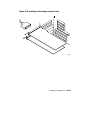
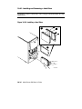
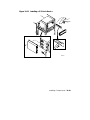
2.6 Installing the Cable Management Bracket
Install the cable management bracket to the rear rails of the cabinet as
described in the following procedure. Use Figure 2-6 as a guide.
Figure 2-6 Installing the Cable Management Bracket
IP00067B
2-12
AlphaServer 800 User’s Guide
The cable management bracket has 1.75-inch (1U) spacing (bottom hole to top hole)
and 25 mm spacing (bottom hole to middle hole).
Install the cable management bracket to the rear of the cabinet with four 10-32 Unuts and four 10-32 screws.as follows:
1.
Clip U-nuts over the holes in the vertical rail corresponding to the holes in the
cable management bracket (two per vertical rail).
2.
Attach the cable management bracket to the cabinet with four 10-32 screws.
Installing a System into a Cabinet 2-13
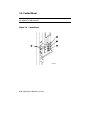
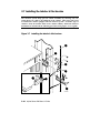
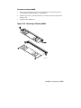
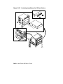
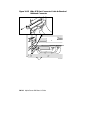
2.7 Installing the Interlock Mechanism
The interlock system helps prevent cabinet instability by allowing only one
system drawer at a time to be pulled out of the cabinet. These parts only work
in a DIGITAL cabinet equipped with the interlock system. If another type of
cabinet is used, the installer must ensure cabinet stability. Install the interlock
mechanism as described in the following procedure, using Figure 2-7 as a guide.
Figure 2-7 Installing the Interlock Mechanism
2
5
3
4
6
7
1
IP00068
2-14
AlphaServer 800 User’s Guide
Install the system into the interlock mechanism of the cabinet as follows:
1.
Install the actuator trip bracket
screws.
2.
Free up the vertical bar
3.
² on the rear of the system with two M4x10 mm
³ of the interlock mechanism.
Insert the stabilizer bracket ´ and the actuator µ latch onto the vertical bar so
that the actuator latch is below the stabilizer bracket.
4.
Insert the vertical bar back in place.
5.
Install a U-nut onto the vertical rail in the second hole above the screw
attaching the slide bracket to the cabinet rail.
6.
Install a second U-nut three holes above the first.
7.
Secure the stabilizer bracket to the cabinet rail with two 10-32 screws.
8.
Vertically position the actuator latch such that the trip bracket aligns with the
center of the actuator latch.
9.
Rotationally orient the actuator latch like all the other actuator latches on the
vertical bar
·
10. Tighten the Allen screws
¸ on the actuator latch.
Installing a System into a Cabinet 2-15
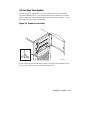
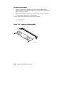
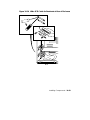
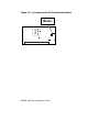
2.8 Connecting the Cables
When making the cable connections, make sure to leave approximately a 76-cm
(30-inch) long segment of cable free so that the system can slide forward. See
Figure 2-8.
Figure 2-8 Cable Loop at the Rear of the System
38 cm
(15 in)
IP00067C
2-16
AlphaServer 800 User’s Guide
Make the cabinet rear connections as follows:
1.
Attach a rear cable first to the cabinet management bracket with a tie-wrap
making sure that a segment of at least 30 inches of cable is available for
extension so that the rackmount system can be pulled out of the cabinet.
2.
Plug in the connectors.
Installing a System into a Cabinet 2-17
Chapter 3
Installing the System
This chapter explains how to set up and install your system. The following topics
are discussed:
•
System Setup Overview
•
Selecting a System Location
•
Identifying Accessories
•
Connecting the System
•
Connecting to Network Hardware
•
Locking Your System
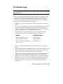
3.1 System Setup Overview
The following list summarizes the steps for setting up your system. The steps may
vary depending on the options in your system.
1.
Select a location for the system, giving consideration to service access,
environmental conditions, and power requirements.
2.
Confirm that you have all the desired accessories that ship with the system and
any additional accessories you may want to add.
3.
Connect the keyboard, mouse, printer, and monitor or terminal.
4.
Connect to the network hardware.
5.
Verify your hardware setup.
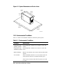
3.2 Selecting a System Location
When choosing a system location, keep in mind the environmental conditions and
power requirements for the system. Figure 3-1 shows the system dimensions and the
clearance needed to access the system for servicing.
Installing the System 3-1
Figure 3-1 System Dimensions and Service Area
22 cm
(9 in)
66 cm
(26 in)
45 cm
(17 in)
216 cm
(85 in)
102 cm
(40 in)
IP00021A
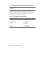
3.2.1 Environmental Conditions
Table 3–1 lists the environmental conditions in which the system operates.
Table 3–1 Environmental Conditions
Condition
Specification
Temperature range
(pedestal systems)
Room temperature: Between 10º C and 40º C (50º F and
104º F).
Temperature range Room temperature: Between 10º C and 35º C (50º F and
(rackmount systems) 95º F).
Relative humidity
Between 10% and 90% (20% to 80% with removable media
options).
Air circulation
Allow a minimum clearance of 15 cm (6 inches) at the rear
of the system to allow for air exhaust and cable egress.
Allow 70 cm (27 inches) at the front for system access and
air intake.
3-2
AlphaServer 800 User’s Guide
3.2.2 Power Requirements
Your system is factory-set to the voltage indicated on the yellow label over the
receptacle. After removing the label, verify that the voltage setting is correct for this
installation. Figure 3-2 shows the power supply requirements and connection.
CAUTION: Powering the system on with the wrong power setting may cause
damage to the power supply.
Figure 3-2 Power Supply Requirements
100-120
100-120
220-240
220-240
V 100-120
V
220-240
100-120VAC 7.0A 50/60 Hz
220-240VAC 3.0A 50/60 HZ
IP00092
NOTE: Current ratings are maximum with a fully loaded system and do not include
a monitor or terminal.
Installing the System 3-3
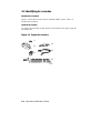
3.3 Identifying Accessories
Standard Accessories
Figure 3-3 shows the accessories that are included with the system. Table 3–2
describes the accessories.
Optional Accessory
An optional accessory that you may need for your modem is the 9-pin to 25-pin PC
to modem cable.
Figure 3-3 System Accessories
1
4
2
5
3
6
IP00091
3-4
AlphaServer 800 User’s Guide
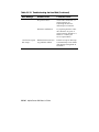
Table 3–2 System Accessories
Accessory
Pedestal system unit keys (2)
User’s Guide and Installation Card
EISA Configuration Utility kit
Mouse
Power cord
Keyboard
Description
Locks and unlocks the pedestal lower door
Installation and operation information
Runs the EISA Configuration Utility
PS/2-style, 3-button mouse
Connects AC power to power supply
104 key keyboard (for DIGITAL UNIX and
Windows NT systems); 108 key keyboard
(for OpenVMS systems)
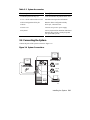
3.4 Connecting the System
Connect the parts of the system as shown in Figure 3-4.
Figure 3-4 System Connections
VT
VGA
System
Modem
Remote
Mgmt.
Modem
IP00094
Installing the System 3-5
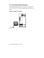
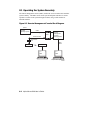
3.5 Connecting to Network Hardware
Your system supports various network options. Generally, the system is configured
with 10/100Base-T Ethernet networks as shown in Figure 3-5. With appropriate
options, you can also connect to ThinWire, FDDI, and AUI Ethernet, and token ring
networks.
Figure 3-5 Network Connections
IP00093
3-6
AlphaServer 800 User’s Guide
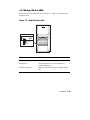
3.6 Locking Your System
Pedestal systems are protected by a key lock located on the lower front door that
prevents unauthorized access. The removable media devices and the system control
panel are always accessible through the upper front door as show in Figure 3-6. The
figure shows the door in the locked position.
Figure 3-6 System Lock and Key
IP00046A
A hole in the back provides additional security by allowing you to attach the system
unit to a post or other fixed object using a Kensington lock.
Installing the System 3-7
Chapter 4
Operating the System
This chapter explains how to start and stop your system. It assumes that you have
set up the hardware and made all necessary connections. Sections in this chapter are:
•
Powering Up the System
•
Booting DIGITAL UNIX
•
Booting OpenVMS
•
Booting Windows NT
•
Booting the Operating System for the First Time
•
Powering Off the System
An integrated server management console allows the user to monitor and control the
system remotely. The operation of the remote management console is discussed in
Chapter 8.
Operating the System 4-1
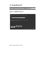
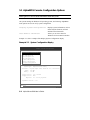
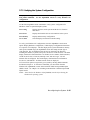
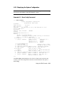
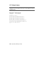
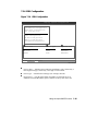
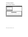
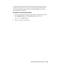
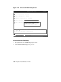
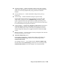
4.1 Powering Up the System
Press the On/Off button on the control panel. The button stays depressed in the
"On" position and the green On/Off indicator on the front of the system lights.
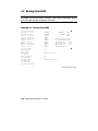
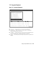
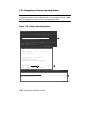
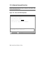
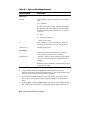
Figure 4-1 Windows NT Power-Up Display
AlphaBIOS Version 5.26
Please select the operating system to start:
Windows NT Server 4.00
Use
and
to move the highlight to your choice.
Press Enter to choose.
Alpha
Press <F2> to enter SETUP
PK-0728A-96
4-2
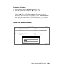
AlphaServer 800 User’s Guide
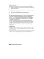
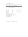
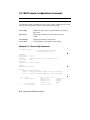
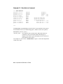
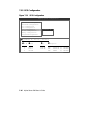
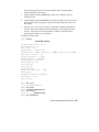
Example 4–1 DIGITAL UNIX and OpenVMS Power-Up Display
ff.fe.fd.fc.fb.fa.f9.f8.f7.f6.f5.ef.df.ee.f4.
probing hose 0, PCI
probing PCI-to-EISA bridge, bus 1
bus 0, slot 5 -- pka -- QLogic ISP1020
bus 0, slot 6 -- vga -- S3 Trio64/Trio32
bus 0, slot 11 -- ewa -- DECchip 21041-AA
bus 0, slot 12 -- pkb -- DEC KZPSA
bus 0, slot 13 -- dra -- Mylex DAC960
ed.ec.eb.....ea.e9.e8.e7.e6.e5.e4.e3.e2.e1.e0.
X4.7-3046, built on Dec 4 1996 at 01:56:52
Memory Testing and Configuration Status
128 Meg of System Memory
Bank 0 = 64 Mbytes(16 MB Per DIMM) Starting at 0x00000000
Bank 1 = 64 Mbytes(16 MB Per DIMM) Starting at 0x04000000
Testing the System
Testing the Disks (read only)
Testing the Network
Change mode to Internal loopback.
Change to Normal Operating Mode.
Operating the System 4-3
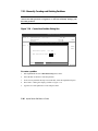
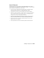
First Time Power On
Make sure to do the following before you power on the system for the first time:
1.
Connect any external options, such as monitors or terminals, or expansion boxes
that house storage devices.
2.
Ensure that the voltage switch in the back of the unit is set to the outlet voltage.
3.
Plug the power cord into the outlet.
4.
Turn on any external options that are connected to the system.
Power On
Press the control panel On/Off button to the “On” position. The green LED lights.
The screen on your monitor or terminal displays test codes and initialization
messages. When the startup procedure is complete, the screen displays the SRM
console prompt or the AlphaBIOS Boot menu, depending on how the os_type
environment variable has been set.
To display any messages that may have scrolled by during the SRM start-up
procedure, enter the cat el command or more el command at the console prompt.
The more el command lists the contents of the event log file one screen at a time.
A normal power-up gives a single beep. A sequence of beeps during start-up
indicates errors.
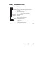
Boot Sequence
If the auto_action environment variable is set to boot or restart and the os_type
environment variable is set to unix or openvms, the DIGITAL UNIX or OpenVMS
operating system boots.
If the system is running the Windows NT operating system (the os_type environment
variable is set to nt), the SRM console loads and starts the AlphaBIOS console.
4-4
AlphaServer 800 User’s Guide
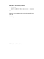
Startup Test Fail
If the system fails the startup tests, do the following:
1.
Turn the system unit off, wait approximately 15 seconds, and then turn it on
again.
2.
If the system continues to fail the startup tests, or emits error beep codes and
halts, refer to Chapter 11, Troubleshooting, for possible reasons.
Operating the System 4-5
4.2 Booting DIGITAL UNIX
®
DIGITAL UNIX can be booted from a local disk, a disk connected through a
cluster, or a remote disk through an Ethernet connection.
Example 4–2 Booting DIGITAL UNIX from a Local Device
>>> show device
dka200.2.0.5.0
DKA200
RZ28M-S
dka400.5.0.5.0
DKA400
RRD45
dkc0.0.0.2003.0
DKC0
RZ25
dva0.0.0.1000.0
DVA0
ewa0.0.0.2000.0
EWA0
08-00-2B-E5-CC-B1
ewb0.0.0.12.0
EWB0
00-00-F8-02-5C-D9
pka0.7.0.5.0
PKA0
SCSI Bus ID 7
pkb0.7.0.2002.0
PKB0
SCSI Bus ID 7
pkc0.7.0.2003.0
PKC0
SCSI Bus ID 7
pkd0.7.0.13.0
PKD0
SCSI Bus ID 7
>>>boot dka400
(boot dka400.5.0.5.0 -flags A)
Building FRU table
block 0 of dka400.5.0.5.0 is a valid boot block
reading 16 blocks from dka100.1.0.5.0
bootstrap code read in
base = 1c8000, image_start = 0, image_bytes = 2000
initializing HWRPB at 2000
initializing page table at 13ff0000
initializing machine state
setting affinity to the primary CPU
jumping to bootstrap code
Digital UNIX boot - Mon Jan 27 19:35:15 EST 1997
Loading vmunix ...
.
.
.
The system is ready.
Digital UNIX Version V4.0 (les058.dec.com) console
login:
4-6
AlphaServer 800 User’s Guide
²
0526
1645
0900
2.10
2.10
2.10
³
´
²
³
´
The show device command displays device information. For some device
types, the full device name is required. (These are devices that have bus node
numbers and channel numbers that are other than 0.) See Section 6.2 for a
description of the show device command and the device naming convention.
In Example 4–2, dk is the device code of the boot device, a is the boot device
controller designation, and 400 specifies the unit number of the boot device.
The operating system banner displays.
The boot command accepts the name of a boot device, a file name through the
-file qualifier, and boot flags through the -flags qualifier. The environment variables
bootdef_dev, boot_osflags, and boot_file can also be used to specify the default
boot device or device list, flag information, and the default boot file. If the qualifiers
and the environment variables are both used, the qualifiers in the command string
override the environment variables.
Operating the System 4-7
4.3 Booting OpenVMS
OpenVMS can be booted from a local disk, a disk connected through a cluster,
or a remote disk through an Ethernet connection.
Example 4–3 Booting OpenVMS
>>> show device
dka200.2.0.5.0
dka400.4.0.5.0
dkc0.0.0.2003.0
dva0.0.0.1000.0
ewa0.0.0.2000.0
ewb0.0.0.12.0
pka0.7.0.5.0
pkb0.7.0.2002.0
pkc0.7.0.2003.0
pkd0.7.0.13.0
>>> sho boot *
boot_arg0
boot_arg1
boot_dev
boot_file
boot_osflags
boot_reset
bootdef_dev
booted_dev
booted_file
booted_osflags
DKA200
DKA400
DKC0
DVA0
EWA0
EWB0
PKA0
PKB0
PKC0
PKD0
RZ28M-S
RRD45
0526
1645
0900
²
08-00-2B-E5-CC-B1
00-00-F8-02-5C-D9
SCSI Bus ID 7 2.10
SCSI Bus ID 7 2.10
SCSI Bus ID 7 2.10
SCSI Bus ID 7
0
³
dka200.2.0.5.0
0
ON
dka4000.4.0.5.0
Continued on next page
4-8
AlphaServer 800 User’s Guide
Example 4–3 Booting OpenVMS (Continued)
´
>>> boot
.
.
.
µ
CPU 0 booting
(boot dka4.4.0.5.0 -flags 0)
Building FRU table
block 0 of dka4.4.0.5.0 is a valid boot block
reading 1002 blocks from dka4.4.0.5.0
bootstrap code read in
base = 200000, image_start = 0, image_bytes = 7d400
initializing HWRPB at 2000
initializing page table at 1f2000
initializing machine state
setting affinity to the primary CPU
jumping to bootstrap code
.
.
.
OpenVMS (TM) Alpha Operating System, Version V7.1
$
²
³
´
µ
The show device command displays device information. For some device
types, the full device name is required. (These are devices that have bus node
numbers and channel numbers that are other than 0.) See Section 6.2 for a
description of the show device command and the device naming convention.
The show boot * command lists all environment variables that begin with the
string “boot.” In this example, a default boot device, dka4.4.05.0, has already
been set.
The boot command needs no device specified, since a default boot device has
been set.
In this example the boot_reset environment variable is set to “on,” so when
the system initializes, it displays the power-up/initialization trace.
The operating system banner displays.
Operating the System 4-9
4.4 Booting Windows NT
Microsoft Windows NT is started from the AlphaBIOS Boot screen.
Figure 4-2 AlphaBIOS Boot Screen
AlphaBIOS Version 5.26
Please select the operating system to start:
Windows NT Server 4.00
Use
and
to move the highlight to your choice.
Press Enter to choose.
Alpha
Press <F2> to enter SETUP
PK-0728A-96
4-10
AlphaServer 800 User’s Guide
The setting of the SRM os_type environment variable determines if AlphaBIOS is
loaded and started on reset and power-up. If os_type is set to nt, after the power-up
display the SRM console is loaded and started, and it then loads and starts the
AlphaBIOS console. AlphaBIOS must be running before Windows NT can be
booted.
The method used for booting Windows NT is determined by the setting of Auto
Start in the AlphaBIOS Standard CMOS Setup screen (Chapter 7).
•
If Auto Start is enabled, the primary version of Windows NT starts
automatically.
•
If Auto Start is disabled, use the arrow keys to select the Windows NT version
to start. Press Enter to boot Windows NT.
NOTE: The SRM console environment variable must be set to graphics before
booting Windows NT. (This setting is not necessary to run AlphaBIOS.) If the Halt
button is in (the LED on the button is lit), the SRM console will not load AlphaBIOS.
This is true even when the os_type environment variable is set to nt.
Operating the System 4-11
4.5 Booting the Operating System for the First Time
Depending on your particular situation, you may need to perform some of the
tasks listed below before booting the operating system.
•
Run the EISA Configuration Utility.
•
Check required environment variable settings.
•
Change the way your system powers up or boots.
•
Verify the system configuration.
4-12
AlphaServer 800 User’s Guide
Running the EISA Configuration Utility
If you have added, removed, or moved an EISA or ISA card, you must run the EISA
Configuration Utility before booting the operating system. Refer to Chapter 7 on
how to run a configuration utility.
Checking Required Environment Variable Settings
You may also want to check that settings for the following variables match your
configuration. Use the SRM set command to reset each variable. To see a complete
list of environment variables, type show * at the SRM console prompt.
Operating system
set os_type
Ethernet device type
set ew*0_mode
Speed for Fast SCSI devices
set pk*0_fast
Boot device
set bootdef_dev
Boot flags
set boot_osflags
Network protocols
set ew*0_protocols
Operating the System 4-13
Verifying the System Configuration
Use the following SRM console commands to verify system configuration for
DIGITAL UNIX and OpenVMS systems.
show config
Displays the buses on the system and the devices found on
those buses.
show device
Displays the bootable devices and contro llers in the system.
show memory
Displays main memory configuration.
set and show
Sets and displays environment variable settings.
To verify your Windows NT configuration, select the AlphaBIOS console menu
option “Display Hardware Configuration,” which displays configuration information
in a sequence of four displays. The first display shows system information, memory,
CPU speed, NVRAM usage, the AlphaBIOS version time stamp, and the type of
graphics detected. The second display lists the devices detected by the firmware,
including the monitor, keyboard, serial ports, and devices on the SCSI bus. The
third display contains PCI slot information: bus number, device number, function
number, vendor ID, device ID, revision ID, interrupt vector, and device type. All
PCI network cards are displayed. The fourth display contains EISA slot information:
slot, device, and identifier. All EISA network cards are displayed.
You can also list options recognized by your system by entering SRM commands
described in Chapter 6. To enter these commands, you must switch from the
Windows NT (AlphaBIOS) console to the DIGITAL UNIX and OpenVMS (SRM)
console. See Chapter 7 on switching to the DIGITAL UNIX and OpenVMS console.
NOTE: Switch back to the Windows NT (AlphaBIOS) console before booting the
Windows NT operating system.
4-14
AlphaServer 800 User’s Guide
4.6 Powering Off the System
You may not need to turn the system off to resolve system hangs or similar
problems. You can often recover from hangs or other problems by pressing the Reset
button on the operator control panel or by issuing a reset command at the remote
management console prompt.
CAUTION: Pressing the Reset button reinitializes the system and causes you to lose
the applications you are running.Within Windows NT, pressing the Ctrl, Alt, and
Delete keys at once allows you to shut down the operating system and bring up the
AlphaBIOS firmware with no loss of data.
Do the following steps to turn the system off:
1.
Shut down the operating system, following the instructions in the operating
system documentation.
2.
Press the On/Off button on the front of the system unit or issue a reset command
at the remote management console prompt.
If you need to turn off your system for an extended period, first turn off power as
described above. Next, unplug the power cord from the power outlet.
Operating the System 4-15
Chapter 5
Reconfiguring the System
This chapter covers the following topics:
•
AlphaBIOS Console Configuration Options
•
SRM Console Configuration Commands
•
Memory Configuration
•
Network Configuration
•
EISA and ISA Options
•
EISA Configuration Utility (ECU)
•
Running ECU
•
Configuring EISA and ISA Options
•
PCI Option Cards
•
Determining SCSI Storage Device IDs
•
Onboard SCSI Bus Configuration
•
Updating Firmware
Your system comes equipped with a 101-key enhanced keyboard that allows you to
communicate with your system by entering data or commands. Note that some
European language keyboards have 102 keys. Use the AlphaBIOS Setup menu to
change the keyboard configuration. Refer to your operating system or application
software documentation for software-specific key functions.
Several SRM console commands or AlphaBIOS console menu options allow you to
examine your system configuration and environment variable settings.
To use these commands or menu options, you need to invoke console mode. Refer
to Chapter 6 on how to invoke console mode.
Reconfiguring the System 5-1
5.1 AlphaBIOS Console Configuration Options
Menu options are used to obtain information about the system.
On systems running the Windows NT operating system, the following AlphaBIOS
menu options are used to verify system configuration:
"Display System Configuration"
Displays system information, devices
detected by the firmware, and PCI
and EISA slot information.
"Set Default Variables"
Allows you to select values for
Windows NT environment variables.
Example 5–1 shows a sample of the Display System Configuration display.
Example 5–1 System Configuration Display
Display System Configuration
Systemboard Configuration
Hard Disk Configuration
PCI Configuration
Eisa Configuration
SCSI Configuration
MC Bus Configuration
Memory Configuration
Integrated Peripherals
System Type:
Processor:
Speed:
Memory:
AlphaServer 800 Family
Digital Alpha 21164, Revision 4.0 (1 Processor)
400 MHz
256 MB
Floppy Drive A:
Floppy Drive B:
Keyboard:
3.5" 1.44 MB
None
U.S. 101-key keyboard
AlphaBIOS Version:
5.26
ESC=Exit
PK-0731B-96
5-2
AlphaServer 800 User’s Guide
Going through each item of the System Configuration Display menu, you can
examine how each part of your system is configured. Refer to Chapter 7 for details
of system configuration displays.
NOTE: You can also list options recognized by your system by entering the
DIGITAL UNIX and OpenVMS commands described in the next section,
SRM Console Configuration Commands. To enter these commands, you
must switch from the Windows NT (AlphaBIOS) console to the DIGITAL
UNIX and OpenVMS (SRM) console. Refer to Chapter 7 for information
about switching to the DIGITAL UNIX and OpenVMS (SRM) console.
Remember to switch back to the AlphaBIOS console before booting the
Windows NT operating system.
Reconfiguring the System 5-3
5.2 SRM Console Configuration Commands
SRM console commands are used to obtain information about the system.
The following console commands are used to verify system configuration on systems
running either the DIGITAL UNIX or OpenVMS operating system:
show config
Displays the buses on the system and the devices found on
those buses.
show device
Displays the bootable devices and controllers in the
system.
show memory
Displays main memory configuration.
set and show
Sets and displays environment variable setting.
Example 5–2 Show Config Command
>>> show config
Digital Equipment Corporation
AlphaServer 800 5/400
Firmware
SRM Console:
ARC Console:
PALcode:
Serial Rom:
²
V4.8
5.26
VMS PALcode V1.19-2, OSF PALcode V1.21-4
X0.4
Processor
DECchip (tm) 21164A-1
400MHz
³
System
Motherboard Revision: 0
Memory
128 Meg of System Memory
Bank 0 = 64 Mbytes(16 MB Per DIMM) Starting at 0x00000000
Bank 1 = 64 Mbytes(16 MB Per DIMM) Starting at 0x04000000
Slot
5
6
7
5-4
Option
QLogic ISP1020
S3 Trio64/Trio32
Intel 82375EB
Hose 0, Bus 0, PCI
pka0.7.0.5.0
dka100.1.0.5.0
dka200.2.0.5.0
dka500.5.0.5.0
Bridge to Bus 1,
AlphaServer 800 User’s Guide
´
SCSI Bus ID 7
RZ28M-S
RZ28M-S
RRD45
Example 5–2 Show Config Command (Continued)
EISA
11
12
DECchip 21041-AA
DEC KZPSA
13
Mylex DAC960
Slot
Option
ewa0.0.0.11.0
pkb0.7.0.12.0
dkb100.1.0.12.0
dkb400.4.0.12.0
dkb600.6.0.12.0
dra.0.0.13.0
dra0.0.0.13.0
dra1.0.0.13.0
00-00-F8-02-5C-D2
SCSI Bus ID 7
RZ28
RZ28D
RZ28
1 Member JBOD
1 Member JBOD
Hose 0, Bus 1, EISA
>>>
µ
The show config command displays all devices found on the system bus, PCI bus,
and EISA bus. You can use the information in the display to identify target devices
for commands such as boot and test, as well as to verify that the system sees all the
devices that are installed.
The configuration display includes the following information:
²
³
´
µ
Version numbers for the firmware code, PALcode, SROM chip, and CPU
Memory size and configuration for each bank of memory
PCI bus information:
•
PCI slot 1— SCSI controller on backplane, along with storage drives on
the bus
•
PCI slot 2—PCI option module
•
PCI slot 3—PCI option module
•
PCI slot 4 or EISA slot 1—PCI or EISA option module
For storage controllers, the attached devices are also displayed.
EISA bus information:
EISA slot 1 or PCI slot 4—EISA or PCI option module
EISA slot 2
EISA slot 3
For storage controllers, the attached devices are also displayed.
Reconfiguring the System 5-5
Example 5–3 Show Device Command
>>> show device
dka100.1.0.5.0
dka200.2.0.5.0
dka500.5.0.5.0
dva0.0.0.1000.0
ewa0.0.0.1001.0
ewb0.0.0.11.0
ewc0.0.0.13.0
pka0.7.0.5.0
>>>
DKA100
DKA200
DKA500
DVA0
EWA0
EWB0
EWC0
PKA0
RZ28M-S
RZ28M-S
RRD45 1645
08-00-2B-3E-BC-B5
00-00-C0-33-E0-0D
08-00-2B-E6-4B-F3
SCSI Bus ID 7 2.10
²
³
´
µ
The show device command displays status for the devices and controllers in the
system. The syntax is:
show device [controller_name]
controller_name
The controller name or abbreviation. When abbreviations or
wildcards are used, all controllers that match the type are
displayed. If no name is given, the display is a list of all devices
and controllers in the system.
The devices displayed are:
²
³
´
µ
SCSI drive
CD-ROM drive
Diskette drive
Ethernet port
SCSI bus
Device naming follows certain conventions. See Displaying System Configuration,
Chapter 6, for the interpretation of device names.
Example 5–4 Show Memory Command
>>> show memory
64 Meg of System Memory
Bank 0 = 64 Mbytes (16 MB Per Dimm) Starting at 0x00000000
Bank 1 = No Memory Detected
The show memory command displays information for each memory card.
5-6
AlphaServer 800 User’s Guide
Example 5–5 Set and Show Commands
>>> set bootdef_dev ewa0
>>> show bootdef_dev
ewa0
>>> show auto_action
boot
>>> set boot_osflags 0,1
>>>
The set and show commands are used to set environment variables. Typically, you
set environment variables when you configure a system.
CAUTION: Environment variables must be entered exactly as shown, not
abbreviated, to be recognized by the system.
The syntax is:
set envar value [-default] [-integer] [-string]
show envar
envar
The name of the environment variable to be modified
(auto_action, bootdef_dev, boot_file, boot_osflags).
value
The value that is assigned to the environment variable.
Options:
-default
-integer
-string
Restores variable to its default value.
Creates variable as an integer.
Creates variable as a string (default).
NOTE: Use the init command to initialize the firmware whenever you reset the
following environment variables: auto _action, console, language, os _type,
bus_probe_algorithm.
Example:
>>> set os_type NT
>>> init
Remember to switch back to the AlphaBIOS console to boot the Windows
NT operating system.
Reconfiguring the System 5-7
5.3 Memory Configuration
The AlphaServer 800 system supports 3.3 volt, dual-in-line memory modules
(DIMM) on the motherboard, providing from 32 Mbytes to 2 Gbytes of ECCprotected RAM.
Figure 5-1 Memory Banks
DIMM 3
Bank 1
DIMM 2
DIMM 1
DIMM 0
DIMM 3
Bank 0
DIMM 2
DIMM 1
DIMM 0
IP00071A
WARNING: Before installing a memory module, turn off all power to the system.
The DIMM modules are grouped in two memory banks, each consisting of four
modules. Figure 5-1 shows the memory bank groupings on the system board. A
minimum of one memory bank (4 modules) is required.
5-8
AlphaServer 800 User’s Guide
5.4 Network Configuration
Connnect your system to networks as explained in this section.
Figure 5-2 Network Connections
IP00093
Reconfiguring the System 5-9
Your system supports various Ethernet network options. Generally, the system is
configured with 10/100 Fast ThinWire, AUI, or 10/100Base-T 100Base-T Ethernet
networks as shown in Figure 5-2. With the correct option, you can also connect to
FDDI and token ring networks.
Any new network device is initially set to AUI mode, which is preserved in memory
until the network type is changed using the following command:
>>> set ewx0_mode mode_name
In this command, x identifies the controller, and mode_name is the mode to be
selected. To determine the controller ID, use the show config command or the
show device command. Refer to the following configuration command examples to
set the network configuration for the network option card:
>>> set ewa0_mode twisted-pair
(10BASE-T/twisted-pair network)
>>> set ewa0_mode full
(full duplex, twisted-pair network)
>>> set ewa0_mode aui
(AUI/standard network)
>>> set ewa0_mode bnc
(ThinWire network)
>>> set ewa0_mode fast
>>> set ewa0_mode fastFD
(full duplex)
>>> set ewa0_mode auto-negotiate
Mode names can be abbreviated; the system prompts you with correct names if you
enter an invalid name. To verify the network setting, use the show command:
>>> show ew*
CAUTION: Modes for all network devices should be reassigned whenever a network
device is moved, installed, or removed because associations between devices and the
device names and modes they are set to may be altered.
5-10
AlphaServer 800 User’s Guide
5.5 EISA and ISA Options
Follow the discussions and procedures given in this section to configure EISA
and ISA option cards.
Figure 5-3 shows EISA and ISA cards. The EISA cards have two interlocking rows
of gold contacts, whereas ISA cards have a single row of gold contacts. The cards
also differ in size.
Figure 5-3 EISA and ISA Cards
ISA
EISA
IP00075
The EISA (Extended Industry Standard Architecture) bus is a 32-bit industry
standard input/output bus. EISA is a superset of the well-established 16-bit ISA bus.
EISA was designed to accept newer 32-bit components while maintaining
compatibility with older 8-bit and 16-bit cards. EISA offers performance of up to 33
MB/sec for cards with bus mastering and DMA capabilities. The motherboard has
two dedicated slots for EISA or ISA modules and one EISA/PCI interchangeable
slot. EISA slots are bus master slots and can be filled in any order.
The ISA (Industry Standard Architecture) bus is an industry-standard, 16-bit I/O bus.
The EISA bus is a superset of the ISA bus and has been designed to be backward
compatible with 16-bit and 8-bit architectures. Therefore, ISA modules can be used
in your system, provided the operating system supports the device.
Figure 5-4 shows the location of EISA and ISA option slots on the system board. To
access the slots, you will need to remove the side panel of the system enclosure. Be
sure to replace the panel before attempting to start the system again.
Reconfiguring the System 5-11
CAUTION: To access the option slots, remove the side panel. An attempt to remove
the top cover while the system is running will shut down the system, with potential
loss of data.
Figure 5-4 EISA, ISA, and PCI Option Slots
PCI11
PCI12
PCI13
PCI14(64-bit)
EISA1
EISA2
PCIOption
Slots
SharedPCI
orEISA
EISAOption
Slots
EISA3
IP00071E
For information about installing a specific option, refer to the documentation for that
option. For information about configuring an EISA option or an ISA option, refer to
later subsections.
WARNING: Before installing EISA or ISA bus options, turn off all power to the
system.
5-12
AlphaServer 800 User’s Guide
5.6 EISA Configuration Utility (ECU)
The EISA Configuration Utility updates the configuration of the EISA and ISA
cards in your system.
Whenever you add, remove, or move an EISA or ISA card, the EISA Configuration
Utility (ECU) must be run. The ECU is a menu-based utility, run from the
AlphaBIOS firmware, that provides online help to guide you through the
configuration process.
NOTE: The ECU is operating system-specific. Two common causes of system
problems are: (1) running the wrong ECU for your operating system; (2)
neglecting to rerun the appropriate ECU when changing operating systems.
Each EISA or ISA card has a corresponding configuration (CFG) file that describes
the characteristics and the system resources required for that option. The ECU uses
the CFG file to create a conflict-free configuration.
The ECU is supplied on the System Configuration Diskettes shipped with your
system. Make copies of these diskettes and keep the originals in a safe place. Use
the backup copies when you are configuring the system. The system configuration
diskettes must have the volume label SYSTEMCFG.
NOTE: The CFG files supplied with the option you want to install may not work if
the option is not supported on your system. Before you install an option,
check your system’s product literature to verify that your system supports
the option.
CAUTION: Turn the system off before you install EISA options.
Reconfiguring the System 5-13
5.7 Configuring EISA and ISA Options
Configure the EISA options and then the ISA options following the instructions
given in this section and subsections.
EISA options are recognized and configured automatically.
NOTE: Do not install ISA cards until after you have run the EISA Configuration
Utility for all EISA cards.
To configure an EISA bus that contains no ISA options, follow these steps:
1.
Install, move, or remove the EISA option card using the instructions provided
with the EISA option.
2.
Invoke the console firmware.
For systems running Windows NT:
a) Insert the ECU diskette into the diskette drive.
b) From the Boot menu, select Utilities.
c)
From Utilities, select Run ECU from floppy.
For systems running DIGITAL UNIX or OpenVMS:
a) Insert the ECU diskette into the diskette drive.
b) At the SRM prompt, enter the ecu command.
There may be a 10 to 20 second delay in system activity while the system recognizes
the ECU. When the firmware has finished loading, the ECU program is booted.
Configure the ISA options in the same manner after you have configured the EISA
options.
5-14
AlphaServer 800 User’s Guide
5.7.1 Running ECU
Configuration utilities are run directly from the AlphaBIOS Utility menu. You
can also run configuration utilities from the SRM console with the ecu
command.
To run a configuration utility:
From AlphaBIOS Setup, select Utilities. From the submenu that is displayed, select
Run ECU from floppy and press Enter.
Figure 5-5 Run ECU from Floppy Dialog Box
AlphaBIOS Setup
Display System Configuration...
Upgrade AlphaBIOS
Hard Disk Setup...
CMOS Setup...
Install Windows NT
Utilities
About AlphaBIOS...
F1=Help
Run ECU from floppy...
OS Selection Setup...
Run Maintenance Program...
PK-0729A-97
NOTE: To run ECU from a terminal connected to a serial line, you must use a
VT320 or VTxxx terminal running in 320 mode. From the AlphaBIOS
console, you must also create the environment variable TERM with a value
of VT320. For example: TERM=VT320. If you later want to run ECU on
a graphics monitor, you must first delete this environment variable.
Reconfiguring the System 5-15
5.7.2 Checking Required Environment Variable Settings
Check the environment variables if you are running DIGITAL UNIX or
OpenVMS.
You may also want to check that settings for the various elements of the system
match your configuration. Table 5–1 gives the SRM console command to reset the
environment variable for each element To see a complete list of environment
variables, type show * at the SRM console prompt.
Table 5–1 Resetting Environment Variables
Element
Reset Environment Variable
Operating system
set os_type
Ethernet device type
set ew*0_mode
Speed for fast SCSI devices
set pk*0_fast
Boot device
set bootdef_dev
Boot flags
set boot_osflags
Network protocols
set ew*0_protocols
5-16
AlphaServer 800 User’s Guide
5.7.3 Verifying the System Configuration
Verify system configuration for DIGITAL UNIX and OpenVMS Alpha systems
using SRM commands. Use the AlphaBIOS console to verify Windows NT
configuration.
Use the following SRM console commands to verify system configuration for
DIGITAL UNIX or OpenVMS Alpha systems.
show config
Displays the buses on the system and the devices found on
those buses.
show device
Displays the bootable devices and controllers in the system.
show memory
Displays main memory configuration.
set and show
Sets and displays environment variable setting.
To verify your Windows NT configuration, select the AlphaBIOS console menu
option "Display Hardware Configuration," which displays configuration information
in a sequence of four displays. The first display shows system information, memory,
CPU speed, NVRAM usage, the AlphaBIOS version time stamp, and the type of
video detected. The second display lists the devices detected by the firmware,
including the monitor, keyboard, serial ports, and devices on the SCSI bus. The third
display contains PCI slot information: bus number, device number, function number,
vendor ID, device ID, revision ID, interrupt vector, and device type. All PCI
network cards are displayed. The fourth display contains EISA slot information:
slot, device, and identifier. All EISA network cards are displayed.
You can also list options recognized by your system by entering SRM commands
described in Chapter 6. To enter these commands, you must switch from the
Windows NT (AlphaBIOS) console to the DIGITAL UNIX and OpenVMS Alpha
(SRM) console. See Chapter 7 on switching to the DIGITAL UNIX and OpenVMS
Alpha console.
NOTE: Switch back to the Windows NT (AlphaBIOS) console before booting the
Windows NT operating system.
Reconfiguring the System 5-17
5.8 PCI Option Cards
No configuration is required for the PCI option. Install the PCI option following
the instructions supplied with the option.
The PCI (Peripheral Component Interconnect) bus is an industry-standard I/O bus
that is the preferred connection for high-performance I/O options. The system
supports three 32-bit and one EISA/PCI interchangeable 64-bit PCI options.
NOTE: A 32-bit PCI option can be installed in a 64-bit slot.
Figure 5-6 shows a PCI option card.
Figure 5-6 PCI Option Card
PCI
IP00075A
Install PCI cards according to the instructions supplied with the option.
CAUTION: Before installing a PCI option, turn off all power to the system.
PCI cards require no additional configuration procedures; the system automatically
recognizes the cards and assigns the appropriate system resources.
5-18
AlphaServer 800 User’s Guide
5.9 Determining SCSI Storage Device IDs
Configuring the storage devices on your system requires assigning the correct
SCSI IDs according to the type of configuration you choose: single-controller,
dual-controller, or triple-controller. Determine SCSI device IDs as explained in
this section.
When you add or remove a drive, a tape drive, or hard drives in the removable drive
area, you may want to consider how these storage devices are configured and
whether you want to reconfigure them. They all reside on one SCSI bus that
connects to the system board and to the SCSI backplane. The system configuration
determines a unique ID for each device. (The diskette drive has its own dedicated
bus and is not included in the SCSI configuration.)
Hard disk drives have their SCSI IDs set automatically according to the slot they are
installed in. Devices added to the removable media bus must have their SCSI IDs set
to avoid conflict with the hard drives. Table 5–2 gives the ID numbers assigned by
the system to the hard drives.
Table 5–2 Hard Drive SCSI ID Numbers
Slot Number Starting from the Left
SCSI Device ID Number
0
0
1
1
2
2
3
3
When adding or changing devices, be careful to avoid assigning device IDs (SCSI
IDs) already in use. Duplicate IDs result in one or more devices not being
recognized by the system.
To determine the available SCSI IDs for all SCSI storage devices from the
AlphaBIOS console, select Display System Configuration from the AlphaBIOS
Boot menu, then the SCSI Configuration.
To determine the available SCSI IDs for all SCSI storage devices from the SRM
console, follow the steps in Table 5–3 and refer to Example 5–6.
Reconfiguring the System 5-19
Table 5–3 Determining Available SCSI IDs (SRM Console)
Step
Action
Result
1
Enter the show device
command to display the
SCSI configuration.
The system responds with a display
similar to Example 5–6.
2
Examine the ADDR column The ADDR column lists the SCSI
in the display.
address of each device connected to the
SCSI bus. The first number in the SCSI
address is the SCSI ID. It must be a
unique number in the range 0 to 6. Any
unused SCSI IDs in this range are
available for use by the devices that you
want to connect to the system.
3
Write down the list of
unused SCSI IDs.
Example 5–6 Determining Device IDs
>>> show device
dka400.4.0.6.0
DKA400
dva0.0.0.0.1
DVA0
ewa0.0.0.2004.0
EWA0
08-00-2B-E5-6A-41
ewb0.0.0.11.0
EWB0
08-00-2B-E1-03-19
pka0.7.0.2001.0
PKA0
5-20
RRD46
AlphaServer 800 User’s Guide
2893
SCSI Bus ID 7
2.10
5.10 Updating Firmware
You can use any one of three sources to update the firmware of your system:
CD-ROM, network, diskette.
You may want to update your system firmware as later versions become available.
The Windows NT (AlphaBIOS) firmware and the DIGITAL UNIX and OpenVMS
(SRM) firmware reside in the flash ROM located on the system board. This section
describes how to update to a later version of firmware. You may also need to recopy
firmware onto the system if the flash ROM should ever become corrupted. To do
this, you would use a different procedure. (See Using the Fail-Safe Loader in
Chapter 11, Troubleshooting.)
You can load firmware into the flash ROM from any of the following sources:
•
CD-ROM
•
Network
•
Diskette
Reconfiguring the System 5-21
5.10.1 Updating Firmware Using the CD-ROM Drive
OpenVMS or DIGITAL UNIX Systems
1.
Enter the show device command:
>>> show device
dka0.0.0.6.0
dka400.4.0.6.0
dva0.0.0.0.1
ewa0.0.0.2004.0
ewb0.0.0.11.0
pka0.7.0.2001.0
DKA0
DKA400
DVA0
EWA0
EWB0
PKA0
RZ26N-S
RRD46
440C
08-00-2B-E5-6A-41
08-00-2B-E1-03-19
SCSI Bus ID 7 2.10
In the above example, the CD-ROM drive has a device ID of dka400.
2.
Load the Firmware Update compact disk into the drive.
3.
Boot the system from the update utility disk, using the device ID determined in
step 1 (in this case, dka400) and the file name given in the Firmware Update
document on the compact disk. For example:
>>> boot dka400
4.
Update the system, entering the following command at the update prompt:
UPD> update
5. Exit from the Firmware Update Utility.
UPD> exit
Windows NT System
NOTE: The latest version of the firmware is available on the World Wide Web:
http://www.windowsnt.digital.com
1.
Shut down the Windows NT operating system. Turn the system off and then on.
2.
Load the Firmware Update media into the drive (CD-ROM or floppy).
3.
At the Boot screen, press F2 to get to the AlphaBIOS Setup menu. Select
Upgrade AlphaBIOS.
4.
Press F10 to update the firmware.
5.
When done, press Enter to restart the system with the new firmware.
5-22
AlphaServer 800 User’s Guide
5.10.2 Updating Firmware Using the Network
To update the firmware using the network, refer to the Read Me instructions on the
Web server.
5.10.3 Updating Firmware Using the Diskette Drive
To update the firmware using the diskette drive:
1.
Insert the diskette with the new firmware version in the diskette drive.
2. Enter the following command at the SRM console prompt:
>>> boot dva0
3. Update the system, entering the following command at the update prompt:
UPD> update
4. Exit from the Firmware Update Utility.
UPD> exit
NOTE: To update your system using the SRM console, use a diskette formatted with
the Alpha boot block. To update using the AlphaBIOS console, use a FAT
formatted diskette.
Reconfiguring the System 5-23
Chapter 6
Using the SRM Console
The SRM console is the command-line interface that supports the DIGITAL UNIX
and OpenVMS operating systems. Sections in this chapter are:
•
Invoking the SRM Console
•
SRM Console Tasks
•
SRM Console Security Features
•
SRM Commands
•
Environment Variables
The console terminal can be either a graphics monitor or a serial terminal. The
graphics monitor is connected to the VGA or TGA module. The serial terminal is
connected to the COM1 (MMJ) port.
6.1 Invoking the SRM Console
In a system running the DIGITAL UNIX or OpenVMS Alpha operating system, do
one of the following steps to invoke the SRM console mode:
•
Shut down the operating system according to the procedure described in your
operating system documentation.
•
Press the Halt button on the control panel until it engages.
If you are in AlphaBIOS and want to switch to the SRM console, do one of the
following steps:
•
Press the Halt button on the control panel until it engages.
•
Select SRM from the Console Selection in the Advanced CMOS Setup screen.
After you have performed tasks in the console mode, you must boot the operating
system with the boot command to revert back to the operating mode.
Using the SRM Console 6-1
6.2 SRM Console Tasks
This section describes typical tasks performed by the SRM console commands.
They include:
•
Displaying the System Configuration
•
Booting the Operating System
•
Testing the System
•
Forcing a System Crash Dump
•
Changing Environment Variables
•
Depositing and Examining Data
•
Reading a File
•
Initializing the System
•
Finding Help
•
Switching from SRM to the AlphaBIOS Console
6-2
AlphaServer 800 User’s Guide
6.2.1 Displaying the System Configuration
Several commands are used to display the system configuration: show config,
show device, show memory, show pal, and show version.
Example 6–1 Show Config Command
>>> show config
Digital Equipment Corporation
AlphaServer 800 5/400
Firmware
SRM Console:
T4.8-29
ARC Console:
5.28
PALcode:
VMS PALcode V1.19-3, OSF PALcode V1.21-5
Serial ROM: X0.4
Processor
DECchip (tm) 21164A-1
400MHz
System
Motherboard Revision: 0
Memory
64 Meg of System Memory
Bank 0 = 64 Mbytes(16 MB Per DIMM) Starting at 0x00000000
Bank 1 = No Memory Detected
Slot Option
Hose 0, Bus 0, PCI
5 QLogic ISP1020
pka0.7.0.5.0
SCSI Bus ID 7
6
S3 Trio64/Trio32
7
Intel 82375EB
11
12
13
Slot
1
Slot
0
2
3
DECchip 21050-AA
DECchip 21040-AA
NCR 53C825
Option
DE425
Option
DECchip 21040-AA
Qlogic ISP1020
Qlogic ISP1020
dka100.1.0.5.0
dka200.2.0.5.0
RZ28M-S
RZ28M-S
dka400.4.0.5.0
RRD45
Bridge to Bus 1, EISA
Bridge to Bus 2, PCI
ewb0.0.0.12.0 00-00-C0-33-E0-0D
pkd0.7.0.13.0 SCSI Bus ID 7
Hose 0, Bus 1, EISA
ewa0.0.0.1001.0 08-00-2B-3E-BC-B5
Hose 0, Bus 2, PCI
ewa0.0.0.2000.0 08-00-2B-E5-CC-B1
pkb0.7.0.2002.0 SCSI Bus ID 7
pkc0.7.0.2003.0 SCSI Bus ID 7
dkc0.0.0.2003.0 RZ25
>>>
The show config command displays a list of devices found on the system bus and
I/O buses. This is the configuration at the most recent initialization. The syntax is:
show config
Using the SRM Console 6-3
Example 6–2 Show Device Command
>>> show device
dka100.1.0.5.0
dka200.2.0.5.0
dka400.4.0.5.0
dkc0.0.0.2003
dva0.0.0.1000.0
ewa0.0.0.1001.0
ewb0.0.0.12.0
ewc0.0.0.13.0
pka0.7.0.5.0
pka0.7.0.2002.0
pka0.7.0.2003.0
DKA100
DKA200
DKA400
DKC9
DVA0
EWA0
EWB0
EWC0
PKA0
PKB0
PKC0
RZ28M-S
RZ28M-S
RRD45 1645
RZ25
0900
08-00-2B-3E-BC-B5
00-00-C0-33-E0-0D
08-00-2B-E6-4B-F3
SCSI Bus ID 7
SCSI Bus ID 7
SCSI Bus ID 7
2.10
2.10
2.10
>>>
The show device command displays status for devices and controllers in the system:
SCSI and MSCP devices, the internal floppy drive, and the network. The syntax is:
show device [controller_name]
controller_name
The controller name or abbreviation. When abbreviations or
wildcards are used, all controllers that match the type are
displayed. If no name is given, the display is a list of all devices
and controllers in the system.
An example of a device name is dka400.4.0.5.0. Figure 6-1 shows the interpretation
of this device name.
6-4
AlphaServer 800 User’s Guide
Figure 6-1 Device Naming Convention
dka0.0.0.0.0
Hose Number:
0 PCI_0 (32-bitPCI); 1EISA
Logical
SlotNumber: For EISA options---Correspond to EISA option physical slot numbers (1-3)
For PCI options:
Slot 5 = SCSI controller on system backplane
Slot 6 = On board graphics adapter
Slot 7 = PCI to EISA bridge chip
Slots 11--14 = Correspond to physical PCI option slots:
PCI11, PCI12, PCI13, and PCI 14 (64-bit)
Channel Number:
Bus Node Number:
Device Unit Number:
AdapterID:
DriverID:
Used for multi-channel devices.
Bus Node ID
Unique device unit number
SCSI unit numbers are forced to 100 x Node ID
One-letteradapterdesignator(A,B,C...)
Two-letter port or class driver designator:
DR--RAID-set device
DV--Floppy drive
EW--Ethernet port (TULIP chip, DECchip 21040)
PK--SCSIport, DK--SCSIdisk, MK--SCSI tape
PU--DSSIport, DU--DSSIdisk, MU--DSSI tape, JK--SCSI monitor
IP00090A
Using the SRM Console 6-5
Example 6–3 Show Memory Command
>>> show memory
128 Meg of System Memory
Bank 0 = 64 Mbytes(16 MB Per DIMM) Starting at 0x00000000
Bank 1 = 64 Mbytes(16 MB Per DIMM) Starting at 0x04000000
>>>
The show memory command displays information about the capacity of each
memory bank, the size of DIMMs used in the memory bank, and the starting address
of each bank.
The syntax is:
show memory
6-6
AlphaServer 800 User’s Guide
Example 6–4 Show PAL Command
>>> show pal
pal
VMS PALcode V1.19-2, OSF PALcode V1.21-4
>>>
The show pal command displays the versions of DIGITAL UNIX and OpenVMS
PALcode. PALcode is the Alpha Privileged Architecture Library code, written to
support Alpha processors. It implements architecturally defined processor behavior.
The syntax is:
show pal
Example 6–5 Show Version Command
>>> show version
version
>>>
V4.8-1249 Jan 16 1997 01:56:52
The show version command displays the version of the SRM console program that is
installed on the system. The syntax is:
show version
Using the SRM Console 6-7
6.2.2 Booting the Operating System
The boot command is used to boot the operating system. In Example 6–6, the
operating system is booted from the SCSI drive b, unit 0.
Example 6–6 Boot Command
>>> boot dkb0
(boot dkb0.0.0.2.1 -flags 0)
Building FRU table
block 0 of dkb0.0.0.2.1 is a valid boot block
reading 1002 blocks from dkb0.0.0.2.1
bootstrap code read in
base = 200000, image_start = 0, image_bytes = 7d400
initializing HWRPB at 2000
initializing page table at 1f2000
initializing machine state
setting affinity to the primary CPU
jumping to bootstrap code
OpenVMS (TM) Operating System, Version 7.1
6-8
AlphaServer 800 User’s Guide
The boot command initializes the processor, loads a program image from the
specified boot device, and transfers control to that image. The syntax is:
boot [-file filename] [-flags [value]] [-halt] [-protocols enet_protocol] [boot_dev]
-file filename
-flags [value]
Specifies additional information to the loaded image or
operating system. In DIGITAL UNIX, specifies boot flags. In
OpenVMS, specifies system root number and boot flags. This
qualifier overrides the setting of the boot_osflags environment
variable. See the boot_osflags environment variable for a list of
settings and their meanings.
-halt
Forces the bootstrap operation to halt and invoke the console
program once the bootstrap image is loaded and page tables and
other data structures are set up. Console device drivers are not
shut down. Transfer control to the image by entering the
continue command.
-protocols
enet_protocol
Either mop (default) or bootp. This qualifier overrides the
setting of the ew*0_protocols environment variable.
boot_dev
A device path or list of devices from which the console program
attempts to boot, or a saved boot specification in the form of an
environment variable. This qualifier overrides the setting of the
bootdef_dev environment variable. Use the bootdef_dev
environment variable to define the default boot device string.
Using the SRM Console 6-9
6.2.3 Testing the System
The test command runs firmware diagnostics for components of the system. This
command is used to test Windows NT systems as well as DIGITAL UNIX and
OpenVMS systems.
Example 6–7 Test Command
>>> test
Testing the Memory
Testing the DK* Disks(read only)
No DU* Disks available for testing
Testing the DR* Disks(read only)
No MK* Tapes available for testing
No MU* Tapes available for testing
Testing the DV* Floppy Disks(read only)
file open failed for dva0.0.0.1000.0
Testing the VGA (Alphanumeric Mode only)
Testing the EWA0 Network
>>>
6-10
AlphaServer 800 User’s Guide
The test command runs firmware diagnostics for the entire core system. The tests
are run concurrently in the background. Fatal errors are reported on the console
terminal. The test command runs one pass of tests.
When using the test command after shutting down an operating system, you must
first initialize the system to a quiescent state. Enter the following commands:
>>> init
[testing]
>>> test
After testing is completed, set the auto_action environment variable to its previous
value (normally boot) and press the Reset button.
See the AlphaServer 800 Service Guide for a more detailed discussion of the test
command.
NOTE: If you are running the Windows NT operating system, switch from
AlphaBIOS to the SRM console to enter the test command. From the
AlphaBIOS console, press in the Halt button (the LED on the button lights)
and reset the system, or select DIGITAL UNIX console (SRM) or
OpenVMS console (SRM) from the Advanced CMOS Setup screen and
reset the system.
The syntax is:
test
Using the SRM Console 6-11
6.2.4 Forcing a System Crash Dump
The crash command forces a crash dump to the selected device on DIGITAL
UNIX and OpenVMS systems.
Example 6–8 Crash Command
>>> crash
CPU 0 restarting
DUMP: 401408 blocks available for dumping.
DUMP: 38535 required for a partial dump.
DUMP: 0x805001 is the primary swap with 401407, start our last
38534
: of dump at 362873, going to end (real end is one more,
for header)
DUMP.prom: dev SCSI 1 3 0 4 400 0 0, block 131072
DUMP: Header to 0x805001 at 401407 (0x61fff)
DUMP.prom: dev SCSI 1 3 0 4 400 0 0, block 131072
DUMP: Dump to 0x805001: ..................: End 0x805001
DUMP.prom: dev SCSI 1 3 0 4 400 0 0, block 131072
DUMP: Header to 0x805001 at 401407 (0x61fff)
succeeded
halted CPU 0
halt code = 5
HALT instruction executed
PC = fffffc00004e2d64
>>>
The crash command forces a crash dump at the operating system level (DIGITAL
UNIX or OpenVMS). This command is used when an error has caused the system to
hang and can be halted by the Halt button or the RCM halt command. This
command restarts the operating system and forces a crash dump to the selected
device. The syntax is:
crash [device]
device is the name of the device to which the crash dump is written.
6-12
AlphaServer 800 User’s Guide
6.2.5 Changing Environment Variables
The set envar and show envar commands are used to set and view environment
variables. The edit command can be used to create a user-defined nonvolatile
environment variable.
Example 6–9 Set envar and Show envar Commands
>>> show console
console
>>> set console serial
>>> show console
console
>>>
graphics
serial
Environment variables pass configuration information between the console and the
operating system. Their settings determine how the system powers up, boots the
operating system, and operates. Environment variables are set or changed with the
set envar command and set to default values with the set -default envar command.
Their values are viewed with the show envar command.
Using the SRM Console 6-13
set envar
The set command sets or modifies the value of an environment variable. It can also
be used to create a new environment variable if the name used is unique. Environ ment variables are used to pass configuration information between the console and
the operating system. The setting of these variables determines how the system
powers up, boots the operating system, and operates. The syntax is:
set [-default] envar value
-default
Restores an environment variable to its default setting.
envar
The name of the environment variable to be modified.
value
The new value of the environment variable.
Whenever you modify the value of any of the following environment variables, the
new value takes effect only after you reset the system by pressing the Reset button or
issuing the initialize command:
console
os_type
show envar
The show envar command displays the current value (or setting) of an environment
variable. The syntax is:
show envar
envar
6-14
The name of the environment variable to be displayed. The wildcard *
displays all environment variables.
AlphaServer 800 User’s Guide
Example 6–10 Edit Command
>>> edit nvram
editing ‘nvram’
0 bytes read in
*10 set mopv3_boot 1
*exit
17 bytes written out to nvram
>>>
The edit command invokes a console editor that behaves much like the line editor
for BASIC. Used to add, insert, or delete lines in a RAM file or the “nvram” powerup script or to create a new environment variable.
In Example 6–10, the nvram script is edited so that an environment variable called
“mop3_boot” is created and set to 1 on each power-up. By default, MOP boots send
four MOP V4 requests before defaulting to MOP V3. This user-created environment
variable forces the SRM console to bypass MOP V4 requests. This speeds up MOP
booting on networks with MOP V3 software.
The syntax is:
edit file
file is the name of the file to be edited.
The editing commands are:
help
Displays the brief help file.
list
Lists the current file prefixed with line numbers.
renumber
Renumbers the lines of the file in increments of 10.
exit
Leaves the editor and closes the file, saving all changes.
quit
Leaves the editor and closes the file without saving changes.
nn
Deletes line number nn.
nn text
Adds or overwrites line number nn with text.
NOTE: It is possible to disable the system by editing the nvram script. For example,
including the command initialize in the script will put the system into an
endless loop.
Using the SRM Console 6-15
6.2.6 Depositing and Examining Data
The deposit command stores data in a specified location. The examine command
displays the contents of a memory location, a register, or a device.
Example 6–11 Deposit Command
>>> dep -b -n 1ff pmem:0 0
# Clear first 512 bytes of
# physical memory.
>>> d -l -n 3 vmem:1234 5
#
#
#
#
>>> d -n 8 r0 ffffffff
# Load GPRs R0 through R8
# with -1.
Deposit 5 into four
longwords starting at
virtual memory address
1234.
>>> d -l -n 10 -s 200 pmem:0 8
# Deposit 8 in the first
# longword of the first 17
# pages in physical memory.
>>> d -l pmem:0 0
# Deposit 0 to physical
# memory address 0.
>>> d + ff
# Deposit FF to physical
# memory address 4.
>>> d scbb 820000
# Deposit 820000 to SCBB.
Example 6–12 Examine Command
>>> examine pc
PC psr: 0 (
PC)
>>> examine sp
gpr:
F0 (
R30)
# Examine the program
# counter.
0000000000001170
# Examine the stack pointer.
0000000000072A60
Continued on next page
6-16
AlphaServer 800 User’s Guide
Example 6–12 Examine Command (Continued)
>>> e -n 6 r4
grp:
grp:
grp:
grp:
grp:
grp:
grp:
20
28
30
38
40
48
50
(
(
(
(
(
(
(
R4)
R5)
R6)
R7)
R8)
R9)
R10)
# Examine register R4 and
# the next six registers.
0000000000005000
000000000FFFE000
00000003F8000C00
0000000053F761AE
0000010000000000
00000003F7800100
00000000000C7FFC
>>> examine pmem:400EC
pmem: 400EC A49D0078A47D0070
# Examine physical memory.
deposit
The deposit command stores data in the location specified. If no options are given
with a deposit command, the system uses the options from the preceding deposit
command.
If the specified value is too large to fit in the data size listed, the console ignores the
command and issues an error response. If the data is smaller than the data size, the
higher order bits are filled with zeros. The syntax is shown below.
examine
The examine command displays the contents of a memory location, a register, or a
device.
If no options are given with an examine command, the system uses the options from
the preceding examine command. If conflicting address space or data sizes are
specified, the console ignores the command and issues an error.
For data lengths longer than a longword, each longword of data should be separated
by a space.
The syntax for both commands is:
deposit [-{b,w,l,q,o,h}] [-{n value, s value}] [space:] address data
examine [-{b,w,l,q,o,h}] [-{n value, s value}] [space:] address
-b
Defines data size as byte.
-w
Defines data size as word.
-l (default)
Defines data size as longword.
-q
Defines data size as quadword.
Continued on next page
Using the SRM Console 6-17
-o
Defines data size as octaword.
-h
Defines data size as hexword.
-d
Instruction decode (examine command only)
-n value
The number of consecutive locations to modify.
-s value
The address increment size. The default is the data size.
space:
Device name (or address space) of the device to access.
address
Offset within a device to which data is deposited. Can be:
data
dev_name
A device name.
fpr- name
The floating-point register set; name is F0 to F31.
gpr- name
The general register set; name is R0 to R31.
ipr- name
The internal processor registers.
pt- name
The PALtemp register set; name is PT0 to PT23.
pmem
Physical memory (default).
vmem
Virtual memory.
Data to be deposited.
Symbolic forms can be used for the address. They are:
pc
The program counter. The address space is set to GPR.
+
The location immediately following the last location referenced in a deposit or
examine command. For physical and virtual memory, the referenced location
is the last location plus the size of the reference (1 for byte, 2 for word, 4 for
longword). For other address spaces, the address is the last referenced address
plus 1.
-
The location immediately preceding the last location referenced in a deposit or
examine command. Memory and other address spaces are handled as above.
*
The last location referenced in a deposit or examine command.
@
The location addressed by the last location referenced in a deposit or examine
command.
6-18
AlphaServer 800 User’s Guide
6.2.7 Reading a File
The more command displays a file one screen at a time.
Example 6–13 More Command
>>> more el
# Display the contents of the
# SRM console’s event log one
# screen at a time.
>>> help * | more
# Display the contents of online
# help one screen at a time.
The more command is similar to that used in the MS-DOS and UNIX operating
systems. It is useful for displaying output that scrolls too quickly to be viewed. For
example, when you power up the system, the system startup messages scroll, and the
messages are logged to an event log. When the >>> prompt displays, you can use the
more command to display the contents of the event log file. The syntax is:
more [file...]
file is the name of the file to be displayed.
Using the SRM Console 6-19
6.2.8 Initializing the System
The initialize command resets the system and executes the power-up tests.
Example 6–14 Initialize Command
>>> init
ff.fe.fd.fc.fb.fa.f9.f8.f7.f6.f5.ef.df.ee.f4.
probing hose 0, PCI
probing PCI-to-EISA bridge, bus 1
bus 0, slot 5 -- pka -- QLogic ISP1020
bus 0, slot 6 -- vga -- S3 Trio64/Trio32
bus 0, slot 11 -- ewa -- DECchip 21041-AA
bus 0, slot 12 -- pkb -- DEC KZPSA
bus 0, slot 13 -- dra -- Mylex DAC960
ed.ec.eb.....ea.e9.e8.e7.e6.e5.e4.e3.e2.e1.e0.
X4.7-3046, built on Dec 4 1996 at 01:56:52
Memory Testing and Configuration Status
128 Meg of System Memory
Bank 0 = 64 Mbytes(16 MB Per DIMM) Starting at 0x00000000
Bank 1 = 64 Mbytes(16 MB Per DIMM) Starting at 0x04000000
Testing the System
Testing the Disks (read only)
Testing the Network
Change mode to Internal loopback.
Change to Normal Operating Mode.
>>>
6-20
AlphaServer 800 User’s Guide
The initialize command resets the system. Issuing this command is equivalent to
pressing the Reset button. The syntax is:
initialize
After self-tests are executed, the system autoboots unless one of the following is
true:
•
The Halt button on the control panel is pushed in.
•
The auto_action environment variable is set to halt.
•
If the auto_action environment variable is set to boot or restart and the Halt
button is not pushed in, the system autoboots. In all other cases, the system stops
in console mode and does not attempt to boot.
Using the SRM Console 6-21
6.2.9 Finding Help
The help (or man) command displays basic information about a command.
Example 6–15 Help (or Man) Command
>>> help set
# or man set
NAME
set
FUNCTION
Set an option or modify the value of an environment
variable.
SYNOPSIS
set <option> <value> or <envar> [-] <value>
where
<option>={host,mode}
where
<envar>={auto_action,bootdef_dev,boot_osflags,...}
[-default]
The help (or man) command displays basic information about the use of console
commands when the system is in console mode. The syntax is:
help (or man) [command . . . ]
command . . .
6-22
Command or topic for which help is requested. The options are:
none
Displays the complete list of commands
for which you can receive help.
command_name
Displays information about the console
command.
argument_string
(such as “sh”)
Displays information about all commands
that begin with that string.
AlphaServer 800 User’s Guide
6.2.10 Switching from SRM to the AlphaBIOS Console
It is necessary to switch to the AlphaBIOS console to run configuration utilities.
To switch from SRM to AlphaBIOS, issue the alphabios command.
Example 6–16 Switching to the AlphaBIOS Console
>>> alphabios
Loading Arc Firmware From Flash
resetting all I/O buses
Arc Firmware Loaded
>>>
The alphabios command loads and starts the AlphaBIOS console. This is necessary
for running AlphaBIOS-based utilities (such as the RAID and EISA configuration
utilities). The syntax is:
alphabios
To return to the SRM console, do one of the following:
If the os_type environment variable is set to unix or openvms, reset the system by
pressing the Reset button.
If the os_type environment variable is set to nt, press the Halt button in (the LED on
the button lights) and reset the system by pressing the Reset button. Alternatively,
select DIGITAL UNIX console (SRM) or OpenVMS console (SRM) from the
Advanced CMOS Setup screen and reset the system.
To switch permanently to the AlphaBIOS console (that is, if the permanent operating
system is changed to Windows NT), do the following:
1.
Set the SRM os_type environment variable to nt.
2.
Set the SRM console environment variable to graphics.
3.
Reset the system with the Reset button or by issuing the initialize command.
4.
Run the EISA Configuration Utility, using the ECU program for Windows NT.
Using the SRM Console 6-23
6.3 SRM Console Security Features
Console security features, which restrict access to certain console commands, are
intended to prevent unauthorized users from modifying system parameters or
otherwise tampering with the system from the console. The SRM console supports
two modes:
Secure mode allows access only to specific console commands: start, continue,
boot (with stored parameters), and login.
User mode allows access to all SRM console commands.
NOTE: The security features work only if access to the system hardware is
controlled. Be sure to keep the front panel of the system locked and the key
secure.
6.3.1 The Set Secure Command
Use the set secure command to enable the security features without restarting the
console. If the console password has already been set, access will be limited to the
start, continue, boot (using the stored parameters), and login commands. For
example:
>>> set secure
Console is secure
If the password has not been set, the console will prompt you to set it. (See the set
password command.)
>>> set secure
Secure not set. Please set the password.
6.3.2 The Set Password Command
Use the set password command to set or change the console password. If the
password has already been set, the console prompts you for the new password and
verification, then for the old password.
>>> set password
Please enter the password:
Please enter the password again:
Now enter the old password:
>>>
NOTE: The password length must be between 15 and 30 alphanumeric characters.
Any characters after the 30th are not stored.
6-24
AlphaServer 800 User’s Guide
6.3.3 The Login Command
Use the login command to turn off the security features and gain access to all the
SRM console commands during a particular session. If a password has not been set
when you enter the login command, you will be prompted to set it, but you need not
do so unless you wish to.
>>> login
Secure not set. Please set the password:
>>>
When the console prompt is redisplayed, the console is no longer in secure mode. If
a password has been set when you enter the login command, you must enter the
password at the prompt:
>>> login
Please enter the password:
If the password you enter matches the current password, secure mode is turned off
and all console commands can be used. You can then return to secure mode by
initializing the system or entering the boot, continue, or start command.
If you forget the password, you can use the login command and the Halt button to
clear the password:
1.
Check that the Halt button is in the “Off” position.
2.
Enter the login command.
3.
When the Enter Password: prompt is displayed, press the Halt button, then
press Return.
4.
Press the Halt button to the “Off” position. The password is now cleared, and
secure mode cannot be reinstated until you set a new password.
NOTE: If you leave the Halt button in after you clear the password, the system will
not boot.
6.3.4 The Clear Password Command
The clear password command clears the environment variable, password, setting it
to zero. You can use this command after you issue the login command to enter user
mode, which allows you access to all the SRM console commands. You must know
the current password to enter user mode from the secure mode. If you do not know
the password, see Section 6.3.3.
>>> clear password
Please enter the password:
Password successfully cleared
Using the SRM Console 6-25
6.4 SRM Commands
Table 6–1 lists the most frequently used SRM console commands;
Table 6–2 gives the command notation formats; and Table 6–3 shows special
characters.
Table 6–1 Summary of SRM Console Commands
Command
Function
alphabios
Loads and starts the AlphaBIOS console.
boot
Loads and starts the operating system.
cat [filename]
Displays a file by scrolling.
clear envar
Resets an environment variable to its default value.
crash
Forces a crash dump at the operating system level.
deposit
Writes data to the specified address.
ecu
Runs the EISA Configuration Utility.
edit
Invokes the console line editor on a RAM file or on the nvram
file (power-up script).
examine
Displays the contents of a memory location, register, or
device.
help
Displays information about the specified console command.
initialize
Resets the system.
man
Displays information about the specified console command.
more [filename]
Displays a file one screen at a time.
memexer
Exercises memory.
memtest
Runs firmware diagnostics for memory.
ps
Displays the processor status.
set envar
Sets or modifies the value of an environment variable.
set host
Connects to a MSCP DUP server on a DSSI device.
6-26
AlphaServer 800 User’s Guide
Table 6–1 Summary of SRM Console Commands (Continued)
Command
Function
show envar
Displays the state of the specified environment variable.
show config
Displays the configuration at the last system initialization.
show device
Displays a list of controllers and their devices in the system.
show memory
Displays memory module information.
show pal
Displays the version of PALcode.
show status
Shows system status during diagnostics.
show version
Displays the version of the console program.
test
Runs firmware diagnostics for the system.
Using the SRM Console 6-27
Table 6–2 Notation Formats for SRM Console Commands
Attribute
Conditions
Length
Up to 255 characters, not including the terminating carriage
return or any characters deleted as the command is entered. A
command longer than 80 characters and without the backslash
character (see Table 6–3) causes display of an error message.
Case
Upper- or lowercase characters can be used for input. Characters
are displayed in the case in which they are entered.
Abbreviation
Only by dropping characters from the end of words. You must
enter the minimum number of characters to identify the keyword
unambiguously. Abbreviation of environment variables is allowed
with the show command.
Options
You can use command options, to modify the environment, after
the command keyword or after any symbol or number in the
command. See individual command descriptions for examples.
Numbers
Most numbers in console commands are in decimal notation. Two
exceptions, both of which use hexadecimal notation, are
addresses and numbers used in the deposit command. The default
radix can be overridden by inserting %d before numbers you want
to express in decimal, %b before binary, %o before octal, or %x
before hexadecimal. Register names (for example, R0) are not
considered numbers and use decimal notation.
No characters
A command line with no characters is a null command. The
console program takes no action and does not issue an error
message; it returns the console prompt. The console supports
command line recall and editing.
Spaces or tabs
Multiple adjacent spaces and tabs are compressed and treated as a
single space. Leading and trailing spaces are ignored.
6-28
AlphaServer 800 User’s Guide
Table 6–3 Special Characters for SRM Console
Character
Function
Return or Enter
Terminates a command line. No action is taken on a
command until it is terminated. If no characters are
entered and this key is pressed, the console just redisplays
the prompt.
Backslash (\)
Continues a command on the next line. Must be the last
character on the line to be continued.
Delete
Deletes the previous character.
Ctrl/A
Toggles between insert and overstrike modes. The default
is overstrike.
Ctrl/B or up-arrow
Recalls previous command or commands. The last 16
commands are stored in the recall buffer.
Ctrl/C or Ctrl/P
Terminates the process that is running. Clears Ctrl/S;
resumes output suspended by Ctrl/O. When entered as part
of a command line, deletes the current line. Ctrl/C has no
effect as part of a binary data stream.
Ctrl/D or left-arrow
Moves the cursor left one position.
Ctrl/E
Moves the cursor to the end of the line.
Ctrl/F or right-arrow
Moves the cursor right one position.
Ctrl/H or Backspace
or F12
Moves the cursor to the beginning of the line.
Ctrl/J
Deletes the previous word.
Ctrl/O
Stops output to the console terminal for the current
command. Toggles between enable and disable. The
output can be reenabled by other means as well: when the
console prompts for a command, issues an error message,
or enters program mode, or when Ctrl/P is entered.
Ctrl/Q
Resumes output to the console terminal that was
suspended by Ctrl/S.
Using the SRM Console 6-29
Table 6–3 Special Characters for SRM Console (Continued)
Character
Function
Ctrl/R
Redisplays the current line. Deleted characters are omitted.
This command is useful for hardcopy terminals.
Ctrl/S
Suspends output to the console terminal until Ctrl/Q is
entered. Cleared by Ctrl/C.
Ctrl/U
Deletes the current line.
*
Wildcarding for commands such as show.
""
Double quotes enable you to denote a string for environment
variable assignment.
#
Specifies that all text between it and the end of the line is a
comment. Control characters are not considered part of a
comment.
6-30
AlphaServer 800 User’s Guide
6.5 Environment Variables
Environment variables pass configuration information between the console and
the operating system. Their settings determine how the system powers up, boots
the operating system, and operates. Environment variables are set or changed
with the set envar command and returned to their default values with the clear
envar command. Their values are viewed with the show envar command.
Table 6–4 Environment Variable Summary
Environment
Variable
Function
auto_action
Specifies the console’s action at power-up, a failure, or a
reset.
bootdef_dev
Specifies the default boot device string.
boot_osflags
Specifies the default operating system boot flags.
com1_baud
Sets the default baud rate of the internal COM1 serial
interface.
com2_baud
Sets the default baud rate of the COM2 serial port.
com1_flow or
com2_flow
com1_modem or
com2_modem
Indicate the flow control on the serial ports
Used by the operating system to determine if a modem is
present.
Continued on next page
Using the SRM Console 6-31
Table 6–4 Environment Variable Summary (Continued)
Environment
Variable
Function
console
Specifies the device on which power-up output is displayed
(serial terminal or graphics monitor).
ew*0_mode
Specifies the connection type of the default Ethernet
controller.
ew*0_protocols
Specifies network protocols for booting over the Ethernet
controller.
kbd_hardware_
type
Specifies the default console keyboard type.
language
Specifies the console keyboard layout.
os_type
Specifies the operating system and sets the appropriate
console interface.
pci_parity
Disables or enables parity checking on the PCI bus.
pk*0_fast
Enables fast SCSI mode.
pk*0_host_id
Specifies the default value for a controller host bus node ID.
pk*0_soft_term
Enables or disables SCSI terminators on systems that use the
QLogic ISP1020 SCSI controller.
tga_sync_green
Specifies the location of the SYNC signal generated by the
DIGITAL ZLXp-E PCI (PBXGA) graphics accelerator
option.
tt_allow_login
Enables or disables login to the SRM console firmware on
other console ports.
These environment variables are described in the following pages.
6-32
AlphaServer 800 User’s Guide
auto_action
Specifies the action the console takes any time the system powers up, fails, or resets.
When the setting involves autobooting, the system boots from the default boot
device specified by the value of the bootdef_dev environment variable. The syntax
is:
set auto_action value
The options for value are:
halt
The system remains in console mode after power-up or a system
crash.
Boot
The system boots automatically when it is turned on and halts after a
system failure.
Restart
The system boots automatically when it is turned on or after it fails.
bootdef_dev
Specifies one or more devices for booting the operating system. When more than one
device is listed, the system searches in the order listed and boots from the first device
with operating system software. The syntax is:
set bootdef_dev boot_device
boot_device
The name of the device on which the system software has been
loaded. To specify more than one device, separate the names with
commas. Enter the command show bootdef_dev to display the
current default boot device. Enter the command show device for a
list of all devices in the system.
Using the SRM Console 6-33
boot_osflags
Passes information to the boot command. That information is dependent on the
operating system to be booted.
When the operating system is DIGITAL UNIX, the syntax is:
set boot_osflags flags_value
The options for flags_value are:
a
Load operating system software from the specified boot device (autoboot). Boot
to multiuser mode.
i
Prompt for the name of a file to load and other options (boot interactively). Boot
to single-user mode.
s
Stop in single-user mode. Boots /vmunix to single-user mode and stops at the #
(root) prompt.
D
Full dump; implies “s” as well. By default, if DIGITAL UNIX crashes, it
completes a partial memory dump. Specifying “D” forces a full dump at system
crash.
When the operating system is OpenVMS, the syntax is:
set boot_osflags root_number,boot_flags
root_number
boot_flags
6-34
Directory number of the system disk on which OpenVMS files are
located. For example:
root_number
Root Directory
0 (default)
[SYS0.SYSEXE]
1
[SYS1.SYSEXE]
2
[SYS2.SYSEXE]
3
[SYS3.SYSEXE]
The hexadecimal value of the bit number or numbers set. To specify
multiple boot flags, add the flag values (logical OR). See Table 6–5.
AlphaServer 800 User’s Guide
Table 6–5 Settings for boot_osflags Bootflags (OpenVMS)
Flags_Value
Bit Number
Meaning
1
0
Bootstrap conversationally (enables you to modify
SYSGEN parameters in SYSBOOT).
2
1
Map XDELTA to running system.
4
2
Stop at initial system breakpoint.
8
3
Perform diagnostic bootstrap.
10
4
Stop at the bootstrap breakpoints.
20
5
Omit header from secondary bootstrap image.
80
7
Prompt for the name of the secondary bootstrap
file.
100
8
Halt before secondary bootstrap.
10000
16
Display debug messages during booting.
20000
17
Display user messages during booting.
Using the SRM Console 6-35
com1_baud and com2_baud
The default baud rate for the AlphaServer 800 system is 9600.
The com1_baud environment variable sets the baud rate for the internal COM1
serial interface. The local console connected to the COM1 (MMJ) always operates
at the default baud rate of 9600. So, if you change com1_baud, communication with
the system is broken. At this point you will not be able to use your serial connection
through the MMJ or your modem through the modem port. You must change the
modem baud under RCM> to match the new environment variable and log into the
system through the modem. An alternate solution is to simply use the VGA monitor.
With the com2_baud environment variable you can set the baud rate to match that
of the device connected to the port.
The syntax is:
set comx_baud baud_value
baud_value
The new baud rate. A list of possible values is displayed by attempting
to set this environment variable to an unacceptable value (for
example, set comx_baud xxx).
com1_flow and com2_flow
Indicate the flow control on the serial ports.
The syntax is:
set comx_flow flow_value
flow_value
Defined values are:
none—No flow control.
software—Use XON/XOFF (default value).
hardware—Use modem signals CTS/RTS.
both—Use SOFTWARE and HARDWARE.
6-36
AlphaServer 800 User’s Guide
com1_modem and com2_modem
Used by the operating system to determine if a modem is present.
The syntax is:
set comx_modem modem_value
modem_value
Defined values are:
on—Modem is present.
off—Modem is not present (defau lt value).
console
The console terminal can be either a graphics monitor or a serial terminal. The
console environment variable specifies which is used. The syntax is:
set console output_device
The options for output_device are:
graphics
(default)
The console terminal is a graphics monitor or a device connected to the
VGA or TGA module.
serial
The console terminal is the device connected to the COM1 port.
Whenever you change the value of console, you must reset the system by pressing
the Reset button or issuing the initialize command.
Using the SRM Console 6-37
ew*0_mode
Sets an Ethernet controller to run an AUI, ThinWire, or twisted-pair Ethernet
network. For the fast setting, the device defaults to fast.
The syntax is:
set ew*0_mode value
The options for value are:
aui
Device type is AUI.
bnc
Device type is ThinWire.
fast
Device type is fast 100BaseT.
fastfd
Device type is fast full duplex 100BaseT.
full
Device type is full duplex twisted pair.
twisted-pair
Device type is 10BaseT (twisted pair).
ew*0_protocols
Enables network prococols for booting and other functions. The syntax is:
set ew*0_protocols protocol_value
The options for protocol_value are:
mop (default)
Sets the network protocol to mop (Maintenance Operations
Protocol), the setting typically used with the OpenVMS operating
system.
bootp
Sets the network protocol to bootp, the setting typically used with
the DIGITAL UNIX operating system.
bootp,mop
When both are listed, the system attempts to use the mop protocol
first, regardless of which is listed first. If not successful, it then
attempts the bootp protocol.
6-38
AlphaServer 800 User’s Guide
kbd_hardware_type
Sets the keyboard hardware type as either PCXAL or LK411 and enables the system
to interpret the terminal keyboard layout correctly.
The syntax is:
set kbd_hardware_type keyboard_type
The options for keyboard_type are:
pcxal (default)
Selects the 102-type keyboard layout.
lk411
Selects the LK411 keyboard layout.
language
Specifies the keyboard layout, which is language dependent. The setting of the
language environment variable must match the language of the keyboard variant.
The syntax is:
set language language_code
The options for language_code are:
0
No language (cryptic)
42
Italiano (Italian)
30
Dansk (Danish)
50
Japanese (JIS)
32
Deutsch (German)
52
Japanese (ANSI)
34
Deutsch (Schweiz) (Swiss)
44
Nederlands (Netherlands)
36
English (American)
46
Norsk (Norwegian)
38
English (British/Irish)
48
Portuguese (Portuguese)
3A
Español (Spanish)
4A
Suomi (Finnish)
3C
Français (French)
4C
Svenska (Swedish)
3E
Français (Canadian)
4E
Belgisch-Nederlands (Dutch)
40
Français (Suisse Romande)
Using the SRM Console 6-39
os_type
The os_type environment variable specifies the default operating system. This
variable is set at the factory to the setting for the operating system purchased. Use
this command to change the factory default setting.
Whenever you change the value of os_type, you must reset the system by pressing
the Reset button or issuing the initialize command.
The syntax is:
set os_type os_type
The options for os_type are:
unix
DIGITAL UNIX is the default operating system, and the SRM firmware
is started during power-up or reset.
openvms
OpenVMS is the default operating system, and the SRM firmware is
started during power-up or reset.
nt
Windows NT is the default operating system. The SRM firmware is
started, and it loads and starts the AlphaBIOS firmware during powerup or reset. (If the Halt button is pushed in so that the LED on the
button lights, this environment variable is overridden, and the SRM
firmware does not load and start the AlphaBIOS console.)
pci_parity
Disables or enables parity checking on the PCI bus.
Some PCI devices do not implement PCI parity checking, and some have a paritygenerating scheme in which the parity is sometimes incorrect or is not fully
compliant with the PCI specification. A side effect of this aberrant behavior is that
superfluous PCI parity errors are reported by the host PCI bridge. In such cases, the
device can be used as long as parity is not checked; disabling PCI parity checking
prevents false parity errors that can cause system problems.
The syntax is:
set pci_parity value
The options for value are:
on
Enables PCI parity checking.
off (default)
Disables PCI parity checking.
6-40
AlphaServer 800 User’s Guide
pk*0_fast
Enables fast SCSI to perform in either standard or fast mode. If the system has at
least one fast SCSI device, set the default controller speed to fast SCSI (1). Devices
on a controller that connects to both standard and fast SCSI devices will perform at
the appropriate rate for the device. If the system has no fast SCSI devices, set the
default controller speed to standard SCSI (0). If a fast SCSI device is on a controller
set to standard, it will perform in standard mode.
The syntax is:
set pk*0_fast scsi_speed
The options for scsi_speed are:
0
The controller is in standard SCSI mode.
1 (default)
The controller is in fast SCSI mode.
pk*0_host_id
Sets the controller host bus node ID to a value between 0 and 7.
Each SCSI bus in the system requires a controller. Buses can theoretically support up
to eight devices; however, the eighth device must always be a controller. Each
device on the bus, including the controller, must have a unique ID, which is a
number between 0 and 7. This is the bus node ID number.
On each bus, the default bus node ID for the controller is set to 7. You do not need to
change the controller bus node ID unless you place two or more controllers on the
same bus.
To list the controllers on your system, enter the command show device. SCSI
devices begin with the letters “pk” (for example, pka0). The third letter is the adapter
ID for the controller. When entering the command set pk*0_host_id, replace the
asterisk with the adapter ID letter.
The syntax is:
set pk*_host_id scsi_node_id
The value for scsi_node_id is the bus node ID, a number from 0 to 7.
Using the SRM Console 6-41
pk*0_soft_term
Enables or disables SCSI terminators for optional SCSI controllers. This
environment variable applies to systems that use the QLogic SCSI controller, though
it does not affect the onboard controller.
The QLogic ISP1020 SCSI controller implements the 16-bit wide SCSI bus. The
QLogic module has two terminators, one for the low eight bits and one for the high
eight bits.
The syntax is:
set pk*0_soft_term value
The options for value are:
off
Disables termination of all 16 bits.
low
Enables low eight bits and disables high eight bits.
high
Enables high eight bits and disables low eight bits.
on (default)
Enables all 16 bits.
diff
Places the bus in differential mode.
tga_sync_green
Sets the location of the SYNC signal generated by the optional ZLXp-E PCI graphics
accelerator (PBXGA). The parameter is a bit mask, where the least significant bit
sets the vertical SYNC for the first graphics card found, the second for the second
found, and so on.
The default for this environment variable is ff. The default must be reset to 00 so the
graphics monitor on a system with a ZLXp-E PCI graphics accelerator will
synchronize.
The syntax is:
set tga_sync_green value
The options for value are:
ff
Synchronizes the graphics monitor on systems that do not use a
ZLXp-E PCI graphics accelerator.
00 (default)
Synchronizes the graphics monitor on systems with a ZLXp-E PCI
graphics accelerator.
6-42
AlphaServer 800 User’s Guide
tt_allow_login
Enables or disables login to the SRM console firmware on alternate console ports. If
the environment variable console is set to serial, the primary console device is the
terminal connected through the COM1 port. The command set tt_allow_login 1
enables logins through either the COM2 port or a graphics monitor.
The syntax is:
set tt_allow_login value
The options for value are:
0
Disables login through the COM2 port or a graphics monitor.
1 (default)
Enables login through the COM2 port or a graphics monitor.
Using the SRM Console 6-43
Chapter 7
Using the AlphaBIOS Console
AlphaBIOS is the graphical interface that supports the Microsoft Windows NT
operating system and some utility programs. This chapter explains how to perform
common system management tasks with AlphaBIOS, and it provides a reference for
the AlphaBIOS screens.
Sections in this chapter are:
•
Starting AlphaBIOS
•
Keyboard Conventions and Help
•
Displaying the System Configuration
•
Updating Firmware
•
Setting Up the Hard Disk
•
Performing Setup Tasks
•
Installing Windows NT
•
Running a Configuration Utility
•
Selecting the Version of Windows NT
•
Switching from AlphaBIOS to the SRM Console
•
Setting Up Password Protection
•
Running AlphaBIOS from a Serial Terminal
NOTE: To run firmware tests on a Windows NT system, switch to the SRM console
and issue the test command.
Using the AlphaBIOS Console 7-1
7.1 Starting AlphaBIOS
Start AlphaBIOS Setup by pressing F2 from the Boot screen displayed at powerup or reset.
Figure 7–1 Boot Screen
AlphaBIOS Version 5.26
Please select the operating system to start:
Windows NT Server 4.00
Use
and
to move the highlight to your choice.
Press Enter to choose.
Alpha
Press <F2> to enter SETUP
PK-0728A-96
7-2
AlphaServer 800 User’s Guide
The Boot screen shown in Figure 7–1 displays at power-up and reset. Press F2 at this
screen to enter the setup program.
The AlphaBIOS Setup screen (Figure 7–2) displays. From this screen you can select
the tasks to perform. Use the arrow keys to select the menu item you want and press
Enter.
Figure 7–2 AlphaBIOS Setup Screen
AlphaBIOS Setup
Display System Configuration...
Upgrade AlphaBIOS
Hard Disk Setup...
CMOS Setup...
Install Windows NT
Utilities
About AlphaBIOS...
Press ENTER to partition or format hard disks.
ESC=Exit
PK-0726-96
Using the AlphaBIOS Console 7-3
7.2 Keyboard Conventions and Help
AlphaBIOS uses universally accepted keys and key combinations for navigating
the interface and selecting items.
Figure 7–3 Typical First-Level Help Screen
Help: CMOS Setup
F1=Key Help
F3
Change color scheme.
F6
Enter Advanced CMOS Setup.
F7
Set factory default CMOS settings.
ESC
Exit CMOS Setup and discard any changes.
F10
Exit CMOS Setup and save changes,
including changes from Advanced CMOS Setup.
ENTER=Continue
PK-0724-96
AlphaBIOS uses DOS and Windows keyboard conventions for navigating the
interface and selecting items. The valid keystrokes are listed in the keyboard help
screens.
Two levels of keyboard help are available. The first level, reached by pressing F1
once, shows explanations of the keystrokes available for the specific part of
AlphaBIOS currently displayed. An example of the help displayed by pressing F1
once, in this case from the CMOS Setup screen, is shown in Figure 7–3.
The second level of keyboard help, reached by pressing F1 from the first help screen,
shows explanations of the keystrokes available for navigating the interface
throughout AlphaBIOS (see Figure 7–4).
7-4
AlphaServer 800 User’s Guide
Figure 7–4 Second-Level Help Screen
AlphaBIOS Setup
F1=Help
Help: Action Keys
TAB
Move highlight forward between fields of a dialog.
SHIFT+TAB
Move highlight backward between fields of a dialog.
Move highlight within a menu, or cycle through available field
values in a dialog window.
ALT+
Drop down a menu of choices from a drop-down listbox.
drop-down listbox can be recognized by the
symbol.
HOME
Move to the beginning of a text entry field.
END
Move to the end of a test entry field.
A
Move to the left or right in a text entry field.
ESC
Discard changes and/or backup to previous screen.
ENTER=Continue
PK-0725-96
Using the AlphaBIOS Console 7-5
7.3 Displaying the System Configuration
The Display System Configuration screen provides information about the
system’s installed processor, memory, attached devices, and option boards.
From the AlphaBIOS Setup screen select Display System Configuration., then
the category for the requisite information.
Figure 7–5 Display System Configuration Screen
Display System Configuration
Systemboard Configuration
Hard Disk Configuration
PCI Configuration
Eisa Configuration
SCSI Configuration
MC Bus Configuration
Memory Configuration
Integrated Peripherals
System Type:
Processor:
Speed:
Memory:
AlphaServer 800 Family
Digital Alpha 21164, Revision 4.0 (1 Processor)
400 MHz
256 MB
Floppy Drive A:
Floppy Drive B:
Keyboard:
3.5" 1.44 MB
None
U.S. 101-key keyboard
AlphaBIOS Version:
5.26
ESC=Exit
PK-0731B-96
7-6
AlphaServer 800 User’s Guide
Use this procedure to display the system configuration.
1.
Start AlphaBIOS, select Display System Configuration, and press Enter.
2.
In the Display System Configuration screen, use the arrow keys to select the
configuration category you want to see.
From this screen, you can view configuration information about these system
components:
•
System board
•
Hard disk
•
PCI bus
•
EISA bus
•
SCSI devices
•
Memory
•
Integrated peripherals
The sections that follow explain the display for each component.
Using the AlphaBIOS Console 7-7
7.3.1 System Board Configuration
Figure 7–6 System Board Configuration
Display System Configuration
F1=Help
Systemboard Configuration
Hard Disk Configuration
PCI Configuration
Eisa Configuration
SCSI Configuration
MC Bus Configuration
Memory Configuration
Integrated Peripherals
1
System Type:
AlphaServer 800 Family
2 Processor:
3
Speed:
4
Memory:
5
Cache:
Digital Alpha 21164, Revision 4.0
400 MHz
256 MB
2 MB
Floppy Drive A: 3.5" 1.44 MB
Floppy Drive B: None
Keyboard: U.S. 101-key keyboard
6 AlphaBIOS Version:
(1 Processor)
5.26
ESC=Exit
PK-0738B-96
7-8
AlphaServer 800 User’s Guide
²
³
´
µ
·
System type — The model number of the system.
Processor — The model and revis ion of the processor chip. Revision level
information can be useful in troubleshooting problems with technical support
personnel.
Speed — The speed at which the processor runs.
Memory — The amount, in megabytes, of main memory in the system.
Cache — The amount, in kilobytes, of static RAM cache memory installed.
AlphaBIOS version — The version of AlphaBIOS currently running on the
system. This field has three parts: major version number is the major revision of
the BIOS; minor version number signifies enhancements that have been made
since the last major revision; build date shows when the BIOS was compiled.
Using the AlphaBIOS Console 7-9
7.3.2 Hard Disk Configuration
Figure 7–7 Hard Disk Configuration
Display System Configuration
Systemboard Configuration
Hard Disk Configuration
PCI Configuration
Eisa Configuration
SCSI Configuration
MC Bus Configuration
Memory Configuration
Integrated Peripherals
1
Disk
Disk
2
0
1
3
4
QLISP1020 #0, SCSI ID 0
Partition 1
Partition 2
6
Unused
QLISP1020 #0, SCSI ID 1
DEC
RZ26
(C) DECT386
Partition 1
Partition 2
5
510
200
200
7
110
MB
MB
MB
MB
8
NTFS
FAT
1001 MB
995 MB
6 MB
NTFS
FAT
PK-0739A-96
NOTE: This screen is for information only; it cannot be edited. To make changes to
the hard disk setup, use the Hard Disk Setup screen (Section 7.5).
7-10
AlphaServer 800 User’s Guide
²
³
´
µ
·
¸
¹
Physical disk ID — Based on the SCSI ID. The disk with the lowest SCSI ID is
disk 0, the disk with the next lowest SCSI ID is disk 1, and so on.
Controller — The brand and model of SCSI chip used on the SCSI controller.
Controller number — Based on how many SCSI controllers of a particular type
are installed in the system. The first controller of a type is always numbered 0.
SCSI ID number — A unique number you assign to each SCSI device ins talled
in the system. This is usually done with jumpers or a thumb wheel attached to
the drive housing.
Size — The raw capacity of the drive. Formatting the drive with different file
systems (for example, FAT and NTFS) may result in different usable sizes
because of the differences in how storage is managed under those file systems.
Partition number — Within a single drive, partition numbers are assigned in
sequential order: 1, 2, 3, and so on. The partitions populate the drive from the
innermost cylinders to the outermost cylinders. If you have a large hard disk
(over 800 MB) and plan to use the FAT file system, it is a good idea to break the
disk into several smaller partitions because the FAT file system uses disk space
more efficiently at smaller partition sizes. This is not a concern for the NTFS
file system, however, as it uses disk space very efficiently at all partition sizes.
Partition size — The raw (unformatted) storage capacity of the partition. Actual
storage space will differ based on the file system with which the partition is
formatted.
Partition format — The file system (if any) used on a partition. This field
displays FAT, NTFS, or unknown (if the partition is unformatted).
Using the AlphaBIOS Console 7-11
7.3.3 PCI Configuration
Figure 7–8 PCI Configuration
Display System Configuration
Systemboard Configuration
Hard Disk Configuration
PCI Configuration
Eisa Configuration
SCSI Configuration
MC Bus Configuration
Memory Configuration
Integrated Peripherals
3
4
Revision
Physical Slot
2
1
Device Name
Device Type
QLogic ISP1020
SCSI
2
Embedded
Intel 82375 PCEB
Digital KZPSX
S3 Trio32/64
Digital DevID=13
Digital 21140
EISA bridge
SCSI
VGA
MM Video
Ethernet
5
0
84
0
32
PCI0-Embedded
1
2
3
4
ENTER=Select
ESC=Exit
PK-0740A-96
7-12
AlphaServer 800 User’s Guide
²
³
´
µ
Device name — The name and model of the device as recorded in th e device’s
firmware.
Device type — Lists the function of the device in the system.
Revision — The revision level of the device signifies the number of times it has
been updated by the manufacturer.
Physical slot — Lists the actual PCI slot number to which the device is attached.
Refer to your system manual for information on the physical location of PCI slot
locations on your particular system board.
You can find additional detail about any of the PCI devices listed in the Advanced
PCI Information screen. Follow this procedure to view this screen:
1.
Press Enter to enable selection in the device list.
2.
Use the arrow keys to select the device for which you want additional detail.
3.
Press Enter, and the detail is displayed.
4.
Press Escape to return to the table of PCI devices.
The Advanced PCI Information screen is shown in Figure 7–9 on the next page.
Using the AlphaBIOS Console 7-13
Figure 7–9 Advanced PCI Information
Advanced PCI Information
2
1
3
Bus Number=0, Device Number=7, Function Number=0
4
Configuration Space:
Register Name
Hex Offset
Vendor ID
Device ID
Command
Status
Revision ID
Prog. I/F
Sub Class Code
Class Code
Cache Line Size
Latency Timer
Header Type
BIST
Base Address 0
00
02
04
06
08
09
0A
0B
0C
0D
0E
0F
10
Hex
Value
8086
0482
0047
0200
05
00
00
00
00
20
00
00
00000000
ENTER=Continue
PK-0741A-96
²
³
´
µ
Bus number — The virtual PCI bus number.
Device number — The PCI bus device number.
Function number — Represents the number assigned to a particular function on
a multifunction device. For example, a combination Ethernet/SCSI controller
would be listed twice, with the first function listed as 0 and the other as 1.
Configuration header space — Displays the information in the selected device’s
PCI configuration space.
7-14
AlphaServer 800 User’s Guide
7.3.4 EISA Configuration
Figure 7–10 EISA Configuration
Display System configuration
Systemboard Configuration
Hard Disk Configuration
PCI Configuration
Eisa Configuration
SCSI Configuration
MC Bus Configuration
Memory Configuration
Integrated Peripherals
1
2
3
Device Name
Device Type
Physical Slot
DEC 5301
FLOPPY
Other
DISK
Embedded
Embedded
ENTER=Select
ESC=Exit
PK-0742A-96
²
³
´
Device name — Includes a three-character manufacturer code, followed by a
three-digit board type, followed by a one-digit revision number.
Device type — Identifies the board type (for example, network).
Physical slot — Lists the actual EISA slot number to which the device is
attached. The embedded EISA system controller is always first on this list.
Using the AlphaBIOS Console 7-15
7.3.5 SCSI Configuration
Figure 7–11 SCSI Configuration
Display System Configuration
Systemboard Configuration
Hard Disk Configuration
PCI Configuration
Eisa Configuration
SCSI Configuration
MC Bus Configuration
Memory Configuration
Integrated Peripherals
1
QLISP1020 #0
KZPSX #0
QLISP1020 #0, SCSI ID 7, SCSI Bus 0
3
4
5
SCSI ID
Device
Size
Description
0
1
4
Disk 0
Disk 1
CD-ROM
4091 MB
4091 MB
2
DEC
DEC
DEC
RZ29L-CA (C)
RZ29L-CA (C)
RRD46
(C)
DECLXTA
DECLXTA
DEC1645
PK-0743A-97
7-16
AlphaServer 800 User’s Guide
²
SCSI controller information — Describes the physical characteristics of the
selected SCSI controller. This line includes:
Controller — Brand and model of SCSI chip used on the SCSI controller.
Controller number — Based on the number of SCSI controllers of a particular
type in the system. The first controller of a type is always numbered 0.
SCSI ID number — A unique number assigned to the SCSI controller. The
standard controller numbering scheme is for controllers to be SCSI ID 7.
³
´
µ
SCSI bus number — Indicates if the controller is first or second in the system.
The first controller is tied to SCSI bus 0, and the second to SCSI bus 1.
SCSI ID — A unique number you assign to each SCSI device in the system.
This is usually done with jumpers or a thumb wheel attached to the drive
housing.
Device type — Displays whether the device is a hard disk, CD-ROM, scanner,
or other type of device.
Size — The raw capacity of the drive. Formatting the drive with different file
systems (for example, FAT and NTFS) may result in different usable sizes
because of differences in the way those file systems manage storage. This is left
blank if it is not applicable to a device (for example, a scanner).
Description — The name and model of the device as recorded in the device’s
firmware.
Using the AlphaBIOS Console 7-17
7.3.6 Memory Configuration
Figure 7–12 Memory Configuration
Display System Configuration
F1=Help
Systemboard Configuration
Hard Disk Configuration
PCI Configuration
Eisa Configuration
SCSI Configuration
MC Bus Configuration
Memory Configuration
Integrated Peripherals
System Memory Configuration
Bank 0: 512 MB (128 MB Per DIMM) -- Starting Address = 0X00000000
Bank 1: 64 MB (16 MB Per DIMM) -- Starting Address = 0X10000000
ESC=Exit
PK-0745-96
7-18
AlphaServer 800 User’s Guide
7.3.7 Integrated Peripherals
Figure 7–13 Integrated Peripherals
Display System Configuration
Systemboard Configuration
Hard Disk Configuration
PCI Configuration
Eisa Configuration
SCSI Configuration
MC Bus Configuration
Memory Configuration
Integrated Peripherals
1
2
3
4
Serial Port 1: Enabled as COM1:
3F8, IRQ4
Serial Port 2: Enabled as COM2:
2F8, IRQ3
Parallel Port 1: Enabled as LPT1:
3BC, IRQ7
PK-0746A-96
²
³
´
µ
Device type — The physical device as it exists on the system board.
MS-DOS name — Shows if the device is enabled, and if it is enabled, the
addressable MS-DOS name for the device.
Port address — The physical memory location from and to which data travels as
it is received into the device, and sent from the device, respectively.
Interrupt — The interrupt request line (IRQ) used by the device to get the CPU’s
attention.
Using the AlphaBIOS Console 7-19
7.4 Updating Firmware
Insert the CD-ROM or diskette with the updated firmware and select Upgrade
AlphaBIOS from the main AlphaBIOS Setup screen. Use the Loadable
Firmware Update (LFU) utility to perform the update. The LFU exit command
causes a system reset.
Figure 7–14 Updating Firmware
AlphaBIOS Setup
Display System Configuration...
Upgrade AlphaBIOS
Hard Disk Setup
CMOS Setup...
Install Windows NT
Utilities
About AlphaBIOS...
Press ENTER to upgrade your AlphaBIOS from floppy or CD-ROM.
ESC=Exit
PK-0726A-96
7-20
AlphaServer 800 User’s Guide
As new versions of Windows NT are released, it might be necessary to upgrade
AlphaBIOS to the latest version. Additionally, as improvements are made to
AlphaBIOS, it might be desirable to upgrade to take advantage of new AlphaBIOS
features.
Use this procedure to upgrade from an earlier version of AlphaBIOS:
NOTE: If jumper J50 is removed, make sure it is reinserted before you start the
upgrade procedure. Otherwise the firmware will not be upgraded.
1.
Insert the diskette or CD-ROM containing the AlphaBIOS upgrade.
2.
If you are not already running AlphaBIOS Setup, start it by restarting your
system and pressing F2 when the Boot screen is displayed.
3.
In the main AlphaBIOS Setup screen, select Upgrade AlphaBIOS and press
Enter. The system is reset and the Loadable Firmware Update (LFU) utility is
started.
4.
When the upgrade is complete, issue the LFU exit command. The system is reset
and you are returned to AlphaBIOS. If you press the Reset button instead of
issuing the LFU exit command, the system is reset and you are returned to LFU.
Using the AlphaBIOS Console 7-21
7.5 Setting Up the Hard Disk
You can perform either an express or a custom hard disk setup. An express
setup, described in this section, creates the recommended partition arrangement
on the first hard disk, but it does not map bad sectors.
Figure 7–15 Hard Disk Setup Screen
Hard Disk Setup
1
Disk
Disk
2
0
1
3
4
5
QLISP1020 #0, SCSI ID 0
6 Partition 1
Unused
510 MB
7 200 MB
310 MB
QLISP1020 #0, SCSI ID 1
Partition 1
Partition 2
1001 MB
995 MB
6 MB
8
NTFS
NTFS
FAT
9
INSERT=New
DEL=Delete
F6=Format
F7=Express
ESC=Exit
PK-0732A-96
7-22
AlphaServer 800 User’s Guide
CAUTION: Hard disk changes are made as soon as they are entered. So, be careful
as you change your hard disk environment to prevent unintended data loss.
²
³
´
µ
·
¸
Physical disk ID — Based on the SCSI ID. The disk with the lowest SCSI ID is
disk 0, the disk with the next lowest SCSI ID is disk 1, and so on.
Controller — Brand and model of SCSI chip used on the SCSI controller.
Controller number — Based on how many SCSI controllers of a particular type
are installed in the system. The first controller of a type is always numbered 0.
SCSI ID number — A unique number you assign to each SCSI device in the
system. This is usually done with jumpers or a thumb wheel attached to the drive
housing.
Size — The raw capacity of the drive. Formatting the d rive with different file
systems (for example, FAT and NTFS) may result in different usable sizes
because of the differences in how storage is managed under those file systems.
Partition number — Within a single drive, partition numbers are assigned in
sequential order: 1, 2, 3, and so on. The partitions populate the drive from the
innermost cylinders to the outermost. If you have a large hard disk (over 800
MB) and plan to use the FAT file system, it is a good idea to break the disk into
several smaller partitions because the FAT file system uses disk space more
efficiently at smaller partition sizes. This is not a concern for the NTFS file
system, since it uses disk space very efficiently at all partition sizes.
Partition size — The raw (unformatted) storage capacity of the partition. Actual
storage space will differ based on the file system with which the partition is
formatted.
Continued on next page
Using the AlphaBIOS Console 7-23
¹
º
Partition format — The file system (if any) used on a partition. This field
displays FAT, NTFS, or unknown (if the partition is unformatted).
Disk setup options
Insert partition (Insert key) — Use this option to create new partitions. Before
creating a new partition, be sure to select an unpartitioned space. Pressing the
Insert key while an already partitioned space is selected causes an informational
error to be displayed.
Delete partition (Delete key) — Use this option to delete existing partitions.
Before deleting a partition, be sure any data you want to save on the partition
has been backed up. Deleting a partition deletes all data on that partition but
leaves the rest of the disk unaffected. Pressing the Delete key while an
unpartitioned space is selected displays an informational error.
Format partition (F6 key) — Format a partitioned space with the FAT file
system.
Express setup (F7 key) — Create the default recommended partition
arrangement for Windows NT.
Exit (Escape key) — Return to the AlphaBIOS Setup screen.
7-24
AlphaServer 800 User’s Guide
An express hard disk setup creates the recommended partition arrangement on the
first hard disk (disk 0). It does not, however, format the large partition with NTFS,
and it does not map bad sectors on the disk. The NTFS formatting can be done
during Windows NT installation.
To perform an express hard disk setup
1.
If you have any needed information on your disk, back it up before proceeding.
2.
Start AlphaBIOS Setup, select Hard Disk Setup, and press Enter.
3.
Press F7 to enter Express Setup.
4.
Press F10 to continue with the setup.
Using the AlphaBIOS Console 7-25
7.5.1 Manually Creating and Deleting Partitions
Use the Create Partition and Delete Partition options if you need to create a
custom hard disk partition arrangement or otherwise manually manage your
hard disk partitions.
Figure 7–16 Create New Partition Dialog Box
Hard Disk Setup
Disk
Disk
0
1
QLISP1020 #0, SCSI ID 3
510 MB
Partition 1
200 MB
Unused
310 MB
Create new partition, Disk 0 Partition 2
NCRC810 #0, SCSI ID 5
1001 MB
Partition 1
995 MB
Partition 2
6 MB
Available space: 310 MB
New Partition Size: 200
ENTER=Continue
NTFS
NTFS
FAT
MB
ESC=Cancel
PK-0733-96
To create a partition
1.
Start AlphaBIOS and select Hard Disk Setup. Press Enter.
2.
Select the disk on which to create the partition.
3.
If one or more partitions already exist on the disk, select the unpartitioned space.
4.
Press Insert. A dialog box displays, similar to Figure 7–16.
5.
Type the size of the partition to create and press Enter.
7-26
AlphaServer 800 User’s Guide
To delete a partition
1.
Start AlphaBIOS and select Hard Disk Setup. Press Enter.
2.
Select the partition to be deleted (see
3.
² in Figure 7–17).
Press Delete. A dialog box displays (see ³).
4.
Press F10 to confirm the deletion.
Figure 7–17 Delete Partition Dialog Box
Hard Disk Setup
Disk
Disk
0
1
QLISP1020 #0, SCSI ID 0
Partition 1
1 Partition 2
Unused
510
200
200
110
MB
MB
MB
MB
QLISP1020 #0, SCSI ID 1
1001 MB
Partition 1
995 MB
Delete Disk 0, Partition
Partition 2
6 MB2
2
NTFS
FAT
NTFS
FAT
The delete operation will destroy all
data on partition 2 of disk 0.
Press F10 to continue.
cancel.
F10=Continue
Press ESC to
ESC=Cancel
PK-0734A-96
Using the AlphaBIOS Console 7-27
7.5.2 Formatting a FAT Partition
AlphaBIOS can format partitions with the FAT file system. Use Windows NT to
format a partition using NTFS.
Figure 7–18 Formatting a FAT Partition
Hard Disk Setup
Disk
0
1
Disk
1
2
QLISP1020 #0, SCSI ID 3
Partition 1
Partition 2
Unused
Delete Disk 0, Partition 2
NCRC810 #0, SCSI ID 5
Partition 1
Partition
2
Choose Format
Method:
510 MB
200 MB
200 MB
110 MB
1001 MB
995 MB
6 MB
F1=Help
NTFS
Unrecognized
NTFS
FAT
Format Method: Standard Format
Standard Format
Quick Format
ENTER=Continue
ESC=Cancel
PK-0735A-96
7-28
AlphaServer 800 User’s Guide
To format a FAT partition
1.
Start AlphaBIOS and select Hard Disk Setup. Press Enter.
2.
Select the partition to be formatted (see
3.
Press F6. A dialog box displays, asking whether to perform a quick or standard
format (see ). If you select Quick Format, the formatting is completed
immediately, but no bad sectors are mapped. If you select Standard Format, a
dialog box similar to that in Figure 7–19 displays while the drive is formatted,
showing the progress of the formatting. Standard formatting maps bad sectors.
4.
Select a format method, and press Enter.
² in Figure 7–18).
³
Figure 7–19 Standard Formatting
Hard Disk Setup
Disk
Disk
0
1
QLISP1020 #0, SCSI ID 3
Partition 1
Partition 2
Unused
510 MB
200 MB
200 MB
110 MB
NCRC810 #0, SCSI ID 5
Partition 1
Partition 2
Disk 0, Partition 2
1001 MB
995 MB
6 MB
200 MB
F1=Help
NTFS
Unrecognized
NTFS
FAT
Formatting...
25%
ESC=Cancel
PK-0736-96
Using the AlphaBIOS Console 7-29
7.6 Performing Setup Tasks
CMOS Setup is used to configure several system parameters. CMOS Setup has
two modes: Standard CMOS Setup is used to configure basic system
parameters; Advanced CMOS Setup is used for system-specific parameters and
password protection.
Figure 7–20 Standard CMOS Setup Screen
CMOS Setup
1 Date:
Time:
Tuesday,
13:22:27
January
21
F1=Help
1997
2 Floppy Drive A: 3.5" 1.44 MB
Floppy Drive B: None
U.S. 101-key keyboard
3 Keyboard:
4
Auto Start: Enabled
Auto Start Count: 30 Seconds
Press
or
to modify date fields.
take effect immediately.
Date modifications will
5
F3=Color
F6=Advanced
F7=Defaults
ESC=Discard Changes
F10=Save Changes
PK-0749B-96
To enter Standard CMOS Setup
Start AlphaBIOS, select CMOS Setup, and press Enter.
7-30
AlphaServer 800 User’s Guide
²
³
´
µ
Date and time — When setting the time, us e the 24-hour format. (For example,
10:00 p.m. is 22:00:00.)
Floppy drive — The only drive type supported is 3.5 inch, 1.44 MB.
Keyboard — The keyboard setting makes it possible to use most language
keyboards. To ensure correct character mappings, the language of your
keyboard, Windows NT, and the keyboard language selection in CMOS Setup
should all match.
Auto start and auto start count — The Auto Start setting determines whether the
primary operating system is automatically started after the system is reset or
power-cycled. The Auto Start Count setting is the amount of time the Boot
screen is displayed before the default system is automatically started. This delay
gives you the opportunity, after resetting or power-cycling the system, to select
another version of Windows NT to start or to enter AlphaBIOS Setup.
Standard CMOS Setup options
Color (F3 key) — Repeatedly cycles through the available AlphaBIOS color
schemes.
Advanced (F6 key) — Displays the Advanced CMOS Setup screen.
Defaults (F7 key) — Restores the default Standard CMOS Setup values
without affecting the Advanced CMOS Setup values.
Discard changes (Escape key) — Restores the settings in effect when you started
CMOS Setup. This option also discards changes made in Advanced CMOS
Setup.
Save changes (F10) — Saves changes made in both the standard and advanced
modes of CMOS Setup.
Continued on next page
Using the AlphaBIOS Console 7-31
Figure 7–21 Advanced CMOS Setup Screen
Advanced CMOS Setup
1 PCI Parity Checking:
Disabled
2 Power-up Memory Test:
Enabled
3 AlphaBIOS Password Option:
4 Console Selection:
F1=Help
Disabled
Windows NT Console (AlphaBIOS)
5 Power-up Memory Test Windows
Length: NTFull
Console (AlphaBIOS)
OpenVMS Console (SRM)
Digital UNIX Console (SRM)
Press
or
to select the firmware console that will be presented
the next time the system is power-cycled.
6
ESC=Discard Changes
F10=Save Changes
PK-0750A-96
To enter Advanced CMOS Setup
1.
Start AlphaBIOS, select CMOS Setup, and press Enter.
2.
In the Standard CMOS Setup screen, press F6.
7-32
AlphaServer 800 User’s Guide
²
³
´
µ
·
PCI parity checking — Enables and disables settings for PCI parity checking,
which ensures data integrity across the PCI bus. Because some third-party PCI
options do not correctly implement PCI parity generation, the default is
Disabled.
Power-up memory test — Enables and disables settings for the power-up
memory test.
Password setup — Enables and disables settings for password setup.
Password protection provides two levels of security for your system: setup,
which requires a password to start AlphaBIOS Setup, and startup, which
requires a password before the system initializes. Startup protection provides
more comprehensive protection than setup protection because the system cannot
be used at all until the correct password is entered.
Console selection — Switches from AlphaBIOS to SRM firmware. If you select
OpenVMS (SRM) or DIGITAL UNIX (SRM), the next time you reset your
system, the SRM firmware will be loaded instead of AlphaBIOS. This menu
selection changes the setting of the os_type environment variable in the SRM
console.
Memory test length — Selects the length of memory testing that will be done the
next time the system is power-cycled.
Advanced CMOS Setup options
Discard changes (Escape key) —Restores those settings in effect when you
started Advanced CMOS Setup. This does not discard changes made to
Standard CMOS Setup.
Save Changes (F10 key) — Saves changes made in Advanced CMOS Setup.
Note that, when exiting CMOS Setup, you must also save your changes at the
Standard CMOS Setup screen for the changes to be stored permanently.
Using the AlphaBIOS Console 7-33
7.7 Installing Windows NT
Install Windows NT from CD-ROM. Up to four versions of the operating system
can be resident in the system at one time.
Figure 7–22 Installing Windows NT
AlphaBIOS Setup
Display System Configuration...
Upgrade AlphaBIOS
Hard Disk Setup...
CMOS Setup...
Install Windows NT
Utilities
About AlphaBIOS...
Press ENTER to install Windows NT.
ESC=Exit
PK-0726B-96
7-34
AlphaServer 800 User’s Guide
If Windows NT was installed at the factory, Windows NT setup will start
automatically the first time the system powers up. If it was not installed, or if you are
installing another version, you must have a CD-ROM drive attached to your system.
NOTE: Steps 1 and 2 in the following procedure are necessary only when you are
first setting up your system. On subsequent installations and upgrades,
begin at step 3.
1.
Use CMOS Setup to set the system date and time: start AlphaBIOS Setup,
select CMOS Setup, and press Enter.
2.
Perform an express hard disk setup: return to the main AlphaBIOS Setup
screen, select Hard Disk Setup, and press Enter.
3.
Put the Windows NT CD into the CD-ROM drive.
4.
Start AlphaBIOS Setup, select Install Windows NT, and press Enter.
5.
Follow the prompts to complete the installation. For more information on
installing Windows NT, refer to the Installation Guide in your Windows NT
software package.
Using the AlphaBIOS Console 7-35
7.8 Running a Configuration Utility
Configuration utilities are run directly from the AlphaBIOS Utilities menu.
Figure 7–23 Run Maintenance Program Dialog Box
AlphaBIOS Setup
Display System Configuration...
Upgrade AlphaBIOS
Hard Disk Setup...
CMOS Setup...
Install Windows NT
Utilities
About AlphaBIOS...
F1=Help
Run ECU from floppy...
OS Selection Setup...
Run Maintenance Program...
PK-0729-96
If you change your system configuration —for example, by adding a new EISA
adapter or another RAID drive, you will have to run an EISA or RAID configuration
utility. As you modify your system, you might be required to run other types of
configuration utilities as well. Configuration utilities (also called maintenance
programs) are run directly from the AlphaBIOS Utility menu.
Users of the OpenVMS Alpha and DIGITAL UNIX operating systems need to switch
from the SRM console to the AlphaBIOS console to run a configuration utility. To
switch, type either of the following commands at the SRM console prompt:
alphabios or ecu. These commands will access the AlphaBIOS Boot menu. To
access the Setup menu from the Boot menu, press F2.
7-36
AlphaServer 800 User’s Guide
To run a configuration utility:
1.
From AlphaBIOS Setup, select Utilities. From the submenu that is displayed,
select Run Maintenance Program and press Enter. See Figure 7–23.
2.
In the Run Maintenance Program dialog box, type the name of the program to
be run in the Program Name field. Then tab to the Location list box, and select
the hard disk partition, diskette, or CD-ROM drive from which to run the
program.
3.
Press Enter to execute the program. See Figure 7-24.
Figure 7-24 Execute Run Maintenance Program
AlphaBIOS Setup
Display System Configuration...
Upgrade AlphaBIOS
Hard Disk Setup...
Run Maintenance Program
CMOS Setup...
Install Windows NT
UtilitiesProgram Name: ecu.exe
About AlphaBIOS...
Location: A:
ENTER=Execute
F1=Help
.
A:
CD:
Disk 0, Partition 1
Disk 0, Partition 2
Disk 1, Partition 1
PK-0730-96
NOTE: If you are running a utility from a diskette, you can simply type the utility’s
name into the Program Name field, and press Enter. The diskette drive is
the default selection in the Location field. Use Alt+Down arrow when a list
box is selected, to open the list.
Using the AlphaBIOS Console 7-37
7.9 Selecting the Version of Windows NT
Up to four images of Windows NT can be resident on the system at one time. It
is necessary to select the version that will be started.
Figure 7–25 Operating System Selections
Operating System Selection Setup
Primary Operating System
Windows NT Server 4.0
Windows NT Server 3.51
Boot Name: Windows NT Server 4.0
Boot File: Disk 0, Partition 2
\os\winnt351\osloader.exe
OS Path:
Disk 0, Partition 1
\WINNT351
OS Options:
INSERT=New
DEL=Delete
F6=Edit
F7=Copy
F8=Primary
F9=Validate
ESC=Discard Changes
F10=Save Changes
Operating System Selection Setup
Windows NT Server 3.51
Windows NT Server 4.0
Primary Operating System
Boot Name: Windows NT Server 3.51
Boot File: Disk 0, Partition 2
\os\winnt400\osloader.exe
OS Path:
Disk 0, Partition 1
\WINNT400
OS Options:
INSERT=New
DEL=Delete
F6=Edit
F7=Copy
F8=Primary
F9=Validate
ESC=Discard Changes
F10=Save Changes
PK-0723-96
7-38
AlphaServer 800 User’s Guide
NOTE: The term “operating system selection,” as it is used in this context, refers to
a version of Windows NT. It does not pertain to the DIGITAL UNIX and
OpenVMS operating systems.
Each operating system selection is a set of information for a version of Windows NT.
It describes the disk and partition containing the OSLOADER.EXE file associated
with a particular operating system installation, as well as the path to the operating
system itself. In addition, the operating system selection contains any options passed
to the operating system during boot.
By default, one operating system selection displays on the AlphaBIOS Boot screen
for each operating system installed on the system. It is not normally necessary to
modify operating system selections, as the Windows NT installation creates and
modifies operating system selections as needed.
Figure 7–25 shows how operating system selections appear in AlphaBIOS.
Using the AlphaBIOS Console 7-39
7.9.1 Designating a Primary Operating System
Multiple versions of Windows NT can be installed at the same time. Each time
you install a separate version of Windows NT a new operating system is created.
You can designate any version as the current operating system.
Figure 7–26 Primary Operating System
AlphaBIOS Version 5.26
Please select the operating system to start:
1
Windows NT Server 4.00
Windows NT Server 3.51
Use
and
to move the highlight to your choice.
Press Enter to choose.
CMOS Setup
Date:
Time:
Friday,
11:26:22
Jan
3
1997
Floppy Drive A: 3.5" 1.44 MB
Floppy Drive B: None
Keyboard: U.S. 101-key keyboard
Auto Start: Enabled
Auto Start Count: 30 Seconds
2
Operating System Selection Setup
Windows NT Server 4.00
Windows NT Server 3.51
Primary Operating System
3
PK-0720A-96
7-40
AlphaServer 800 User’s Guide
Multiple versions of Windows NT can be installed at the same time. This can be very
useful in a variety of circumstances for example, when testing application
compatibility across different versions of Windows NT.
Each time you install a separate version of Windows NT, a new operating system
selection is created. Although you can start any of the installed versions of Windows
NT, one of them must be the primary operating system. The version of Windows NT
you select as the primary operating system is the one that automatically starts if the
Auto Start option is enabled in AlphaBIOS.
Figure 7–26 illustrates the relationship between multiple-operating-system
installations, Auto Start, and the primary operating system.
²
³
´
The primary operating system is listed first on the Boot screen.
The primary operating system starts automatically if the Auto Start option is
enabled in CMOS Setup.
The primary operating system can be selected in the Operating System
Selection Setup screen.
Follow this procedure to designate a new primary operating system:
1.
From the AlphaBIOS Setup screen select Utilities. In the selection box that
displays, choose OS Selection Setup.
2.
The Operating System Selections Setup screen displays. Select the primary
operating system from the list displayed.
Using the AlphaBIOS Console 7-41
7.9.2 Primary Operating System and the Auto Start Option
The process of setting up your operating system selections is similar to using an
editor. You can make changes to your operating system selections and then
either save your changes or exit without saving.
Figure 7–27 Operating System Selection Setup
Operating System Selection Setup
1
Windows NT Server 4.0
Primary Operating System
2 Boot Name: Windows NT Server 4.0
3 Boot File: Disk 0, Partition 2
\os\winnt351\osloader.exe
4 OS Path:
Disk 0, Partition 1
\WINNT400
5 OS Options:
6
INSERT=New
DEL=Delete
F6=Edit
F7=Copy
F8=Primary
F9=Validate
ESC=Discard Changes
F10=Save Changes
PK-0737A-96
AlphaBIOS boots Windows NT in two stages. The first stage involves reading an OS
Loader program from a disk. As of Windows NT version 4.0, the name of the OS
Loader program is OSLOADER.EXE. The selection for the operating system must
describe the path where AlphaBIOS will find the OS Loader program. Note that the
OS Loader program must be located on a partition formatted with the FAT file
system.
Once the OS Loader program executes, it uses the services provided by AlphaBIOS
to load the operating system components. After the operating system is loaded, the
OS Loader starts execution of the operating system.
7-42
AlphaServer 800 User’s Guide
²
³
´
Primary operating system — The OS that appears first on the AlphaBIOS Boot
screen. It is also the version of the OS that automatically starts if Auto Start is
selected. Any of the operating system selections can be the primary operating
system.
Boot name — Each boot name is associated with an operating system selection.
Windows NT setup automatically creates a boot name each time you install the
operating system. Because the boot name is only a name, you can modify it at
any time without affecting the rest of the operating system selection. Note that
the boot name must have at least one character.
Boot file — Describes the disk, partition, path, and name of the file that
AlphaBIOS passes control to during the process of starting the operating system.
This setting is created along with the operating system selection during
Windows NT setup, and it is usually not modified by the user. However, this
setting can be modified if necessary. For example, a developer testing different
versions of OSLOADER.EXE can store the different versions in different
locations and modify this line to start the operating system with the different
versions as needed.
During Operating System Selection Setup, you can select the disk and partition
for the location of the boot file from a list of choices presented in a list box. To
open a list of values for the field, press the Alt and down arrow keys together.
When you select a boot file location and name, AlphaBIOS searches for the
specified program on the specified partition. If the search fails, a warning
displays, saying that the file does not exist. You are given the choice to continue
with the changes anyway or to cancel the operation and fix the problem.
Note that because the boot file must be located in a FAT partition, only FAT
partitions are available as the boot partition within the list box.
Continued on next page
Using the AlphaBIOS Console 7-43
µ
·
OS path — Describes the disk, partition, and path to the operating system root
directory for an operating system selection.
During Operating System Selection Setup, you can select the disk and partition
for the location of the boot file from a list of choices presented in a list box. To
open a list of possible values for the field, press the Alt and down arrow keys at
the same time. When you select or enter an OS path, AlphaBIOS searches for
the directory. If the search fails, a warning displays, saying that the directory
does not exist. You are given the choice to continue with the changes anyway or
to cancel the operation and fix the problem.
OS options — Lists the startup parameters passed to the operating system for an
operating system selection. One example of a startup parameter is whether to
start the operating system in debug mode. By default, Windows NT does not add
any entries to this field. This field can be modified.
Operating System Selection Setup options — You can use the options listed at
the bottom of the screen to edit operating system selections. When you edit an
OS selection, the fields of the OS selection are validated when you exit the OS
Selection Setup screen. Depending on the option you choose, one of the
following dialog boxes will display.
New OS selection (Insert key) — Displays the Insert New Operating System
Selection dialog box, with default values for the new OS selection already filled
in. You can change these values as necessary.
Delete OS selection (Delete key) — Tags the currently selected OS selection for
deletion. Although the OS selection is removed from the screen, it is not actually
deleted until you save changes.
You can also delete all of your OS selections at once by pressing the Control and
Delete keys at the same time while in the Operating System Selection Setup
screen.
NOTE: If you delete all the OS selections, a dialog box displays informing you
that no OS selections exist and offering three options. You can create a
new OS selection, exit without saving changes, or exit and save
changes.
Continued on next page
7-44
AlphaServer 800 User’s Guide
Edit OS selection (F6 key) — Edit all values of an OS selection by selecting the
OS selection to edit and pressing F6. A dialog box displays with current
information. You can then edit the OS selection fields.
Copy OS selection (F7 key) — Create a new OS selection by using an existing
OS selection as a template. To do this, select the OS selection you want to copy
and press F7. A dialog box displays with the values of your OS selection. You
can then edit the OS selection fields. Note that if you do not make any changes,
a duplicate copy of the OS selection you copied is made.
Primary operating system (F8 key) — Sets the selected OS selection as the
primary operating system. When you make an OS selection primary, it is
displayed first on the Operating System Selection Setup screen with the text
“Primary Operating System.” In addition, the primary operating system is
displayed first on the AlphaBIOS Boot screen and is automatically started if
Auto Start is enabled.
Validate OS selection (F9 key) — Validates the fields in the currently selected
OS selection. The validation routine checks that the OS loader file and OS
directory fields contain valid paths, and that the OSLOADER.EXE file exists in
the directory specified. At the end of the validation, a dialog box displays
describing the results of the validation. If there is an error in an OS selection, the
validation routine displays a dialog box describing the component of the OS
selection that is in error. At this point you can choose to edit the OS selection to
correct the error, or delete the OS selection altogether.
You can also validate all OS selections at once by pressing the Control and F9
keys at the same time. All OS selections are validated in the order they are listed
on screen.
Discard changes (Escape key) — Returns to the AlphaBIOS Setup screen
without saving changes.
Save changes (F10 key) — Saves changes and returns to the AlphaBIOS Setup
screen.
Using the AlphaBIOS Console 7-45
7.10 Switching from AlphaBIOS to the SRM Console
It is necessary to switch to the SRM console to boot DIGITAL UNIX or
OpenVMS or to run firmware-based diagnostics. To switch from AlphaBIOS to
the SRM console, press in the Halt button (the amber LED lights) and reset the
system, or select DIGITAL UNIX (SRM) or OpenVMS (SRM) from the
Advanced CMOS Setup screen and reset the system.
Figure 7–28 Switching to the SRM Console
Advanced CMOS Setup
PCI Parity Checking:
Disabled
Power-up Memory Test:
Enabled
AlphaBIOS Password Option:
Console Selection:
F1=Help
Disabled
Digital UNIX Console (SRM)
Console (AlphaBIOS)
Power-up Memory Test Windows
Length: NTFull
OpenVMS Console (SRM)
Digital UNIX Console (SRM)
Press
or
to select the firmware console that will be presented
the next time the system is power-cycled.
ESC=Discard Changes
F10=Save Changes
PK-0750B-96
7-46
AlphaServer 800 User’s Guide
DIGITAL UNIX and OpenVMS are booted and firmware-based diagnostics are run
from the SRM console. Follow this procedure to switch from AlphaBIOS to SRM:
1.
Select CMOS Setup and press Enter.
2.
In the CMOS Setup screen press F6. The Advanced CMOS Setup screen
displays.
3.
Select DIGITAL UNIX console (SRM) or OpenVMS console (SRM) and
press F10.
4.
The CMOS Setup screen displays. Press F10 to save the change.
5.
Run the EISA Configuration Utility, using the ECU diskette for DIGITAL UNIX
and OpenVMS.
NOTE: ECU must be run before booting DIGITAL UNIX or OpenVMS .
6.
Reset the system.
Alternatively, you can press the Halt button (the LED on the button lights) and reset
the system.
The method you choose depends on how you want the system to function on
subsequent resets:
•
If you make the selection in the Advanced CMOS Setup screen, the system will
continue to stop in the SRM console whenever it is powered-up, reset, or
initialized until the Windows NT operating system is again specified.
•
If you press the Halt button and reset, no system setup information is changed,
and AlphaBIOS will start the next time the system is powered-up, reset, or
initialized with the Halt button out (the amber LED is off).
To return to the AlphaBIOS console, issue the command alphabios at the SRM
console prompt.
Using the AlphaBIOS Console 7-47
7.11 Setting Up Password Protection
Password protection provides two levels of security for your system: setup
protection and startup protection.
Figure 7–29 Advanced CMOS Setup Menu
Advanced CMOS Setup
PCI Parity Checking:
Disabled
Power-up Memory Test:
Enabled
AlphaBIOS Password Option:
Console Selection:
F1=Help
Disabled
Windows NT Console (AlphaBIOS)
Press
or
to select the firmware console that will be presented
the next time the system is power-cycled.
ESC=Discard Changes
F10=Save Changes
PK-0750C-96
7-48
AlphaServer 800 User’s Guide
Password protection provides two levels of security for your system: setup
protection and startup protection. When system setup protection is enabled, a
password is required to start AlphaBIOS setup. When startup password protection is
enabled, a password is required before the system initializes.
To enable password protection:
1.
From the AlphaBIOS Setup screen, select CMOS Setup and press Enter.
2.
In the CMOS Setup screen, press F6 to enter Advanced CMOS Setup mode.
3.
In the Advanced CMOS Setup screen, shown in Figure 7–29, select
AlphaBIOS Password Option. Use the arrow keys to select the type of
protection you want. An explanatory dialog box appears. Read the dialog box
and press Enter to continue.
4.
Enter your password in the Enter New Password dialog box then press Enter.
5.
Enter your password in the Confirm New Password dialog box then press
Enter.
6.
Press F10 to save your changes.
NOTE: If you want to change your password, simply set up your password again.
Using the AlphaBIOS Console 7-49
7.12 Running AlphaBIOS from a Serial Terminal
You can set up a serial terminal to run the AlphaBIOS console and the ECU.
You can interface with the AlphaBIOS console and run the ECU from a serial
terminal (VT200 or higher, or equivalent). Table 7-1 gives the serial terminal key
equivalents of the graphics monitor keyboard commands.
Table 7-1 Serial Terminal Key Commands for AlphaBIOS and ECU
Graphics Terminal Command
Serial Terminal Key Equivalent
F1
CTRL + A
F2
CTRL + B
F3
CTRL + C
F4
CTRL + D
F5
CTRL + E
F6
CTRL + F
F7
CTRL + P
F8
CTRL + R
F9
CTRL + T
F10
CTRL + U
Insert
CTRL + V
Delete
CTRL + W
Backspace
CTRL + H
ESC
CTRL + [
7-50
AlphaServer 800 User’s Guide
To use a serial terminal with AlphaBIOS or ECU:
1.
2.
Invoke the terminal setup utility as described in the documentation for the serial
terminal and change settings as follows:
•
From the General menu, set the terminal mode to VTxxx, 8-bit controls.
•
From the Comm menu, set the character format to 8 bits, no parity, and set
receive to 128 or greater.
•
From the Keyboard menu, set the keyboard so that the tilde (~) key sends
the escape (ESC) signal.
Enter the following commands at the SRM console prompt to set the console
terminal to receive input in serial mode:
>>> set console serial
>>> init
.
.
! Now switch to the serial terminal
>>> show console
console
serial
Using the AlphaBIOS Console 7-51
Chapter 8
Server Management Console
This chapter describes the function and operation of the integrated server
management console. Sections are:
•
Operating the System Remotely
•
RMC Functions
•
First Time Setup
•
Resetting the RMC to Factory Defaults
•
Remote Management Commands
Server Management Console 8-1
8.1 Operating the System Remotely
The remote management console (RMC) enables the user to monitor and control the
system remotely. The RMC resides on the system backplane and allows a remote
operator to connect to the system through a modem, using a serial terminal or
terminal emulator.
Figure 8-1 Remote Management Console Block Diagram
System
SRM/AlphaBIOS
Consoles
Operating System
COM1
>>>set com1_baud
UART
RMC>set baud
Remote
Management
Console
Microprocessor
RMC Modem
Port
Modem
9600
Baud
Modem
>>>
RMC
>>>
RMC
Script Console (MMJ) Port
P00086A
I
8-2
AlphaServer 800 User’s Guide
8.2 RMC Functions
This remote management console (RMC) is accessible to the operator through
either of two serial lines: the standard console terminal COM1 (MMJ) port or
the RMC modem port.
You can access RMC through one of two serial lines: the standard console terminal
COM1 (MMJ) port or the RMC modem port (9-pin DIN).
•
To enter the RMC console remotely, dial in through a modem, enter a password,
and then type a special escape sequence that invokes the RMC command mode.
The default escape sequence is either ^[^[rmc, or ^[^[rcm. These are
equivalent to <Esc><Esc>rmc and <Esc><Esc>rcm, where <Esc> is the escape
key on a PC keyboard. Some AlphaServer 800 units respond to ^[^[rmc and
others to ^[^[rcm. So, if you cannot invoke the RMC command mode using
one default sequence, use the alternate default sequence. The default string can
be changed using the set escape command. Before you can dial in remotely,
you must set up the RMC initialization and dial strings. Refer to Section 8.3 for
first time setup instructions.
•
To enter the RMC console locally, type the escape sequence at the SRM console
prompt on the local serial console terminal (MMJ).
You can also enter the RMC console from the local graphics monitor by entering the
RMC command at the SRM console prompt, and then entering the escape sequence.
When finished accessing the RMC console from the graphics monitor, enter the reset
command to restore the RMC and SRM consoles.
Once connected to the RMC, you can use a special set of remote console commands,
distinct from the standard SRM and AlphaBIOS consoles. The RMC commands
allow the operator to remotely monitor power supply status, system temperature, and
fan status. They also allow the remote operator to exercise control over the system
equivalent to using the system control panel: Power off/on, Reset, and Halt (in/out).
The RMC logic can dial a preset telephone number when it detects system alarm
conditions. A typical scenario might be:
1.
RMC detects an alarm condition due to excessive temperature.
2.
RMC dials the operator’s pager and sends a message identifying the system.
3.
Operator dials the system from a remote serial terminal.
4.
Logging into the RMC, the operator checks system status and powers down the
system.
5.
Later the operator powers up the system and reboots.
Server Management Console 8-3
The remote operator can disconnect (using the quit command) from the RMC and
connect to the system’s COM1 port. This allows the operator to use the remote
terminal to communicate with the software and firmware that normally use the local
serial terminal:
•
SRM and AlphaBIOS firmware consoles
•
ECU and RCU configuration utilities
•
Operating systems
The RMC also provides a watchdog timer, whose interval is set using the RMC set
wdt command. If the system fails to respond within the watchdog timer interval, the
RMC recognizes an alert and dials the remote operator. (This assumes that dial-out
alerts have been set up using the commands enable remote, set dial, and enable
alert). The watchdog timer alert also causes the RMC to reboot the system
automatically, if the enable reboot command has been issued.
8-4
AlphaServer 800 User’s Guide
8.3 First Time Setup
Use the procedure described below to be able to dial in remotely through the
RMC modem port.
Before you can dial in remotely through the RMC modem port or enable the system
to call out to a remote operator in response to system alerts, a modem must be
connected and several RMC strings and parameters must be set. Use the following
procedure to set up RMC strings, password and parameters; and to send out a test
alert to verify that the modem strings are set correctly.
1.
From the local console terminal, enter the RMC escape sequence at the SRM
prompt.
You can also enter the RMC console from the local graphics monitor by entering
the rmc command at the SRM console prompt, and then entering the escape
sequence. When finished accessing the RMC from the graphics monitor, enter
the reset command to restore the RMC and SRM consoles.
2.
Using the RMC command set init, assign the modem initialization string
appropriate for your modem. Some typical initialization strings are:
Modem
Initialization String
Motorola 3400 Lifestyle 28.8
at&f0e0v0x0s0=2
AT &T Dataport 14.4/FAX
at&f0e0v0x0s0=2
Hayes Smartmodem Optima 288 V34/V.FC + FAX
at&fe0v0x0s0=2
Refer to your modem documentation for more information on its initialization
strings.
3.
Using the RMC commands set dial and set alert, assign a dial string to be called
when the RMC detects an alert condition, as well as a string to be used with a
paging service, usually a call-back number for the paging service.
When an alert is sent, the dial string and alert string are concatenated and sent to
the modem. Note that the dial and alert strings must be in the correct string
format for the attached modem. If a paging service is to be contacted, then the
dial and alert strings must include the appropriate modem commands to dial the
number, wait for the line to connect, and send the appropriate touch tones to
leave a pager message. Elements of a dial and alert strings are provided in
Table 8-1.
Server Management Console 8-5
Table 8-1 Dial and Alert String Elements
String Elements
Description
Dial String
ATXDT
(Enter characters either in all upper case or all lower
case).
AT = Attention
X = Forces the modem to dial “blindly” (not look for
the dial tone). Enter this character if the dial-out line
modifies its dial tone when used for services such as
voice mail.
D = Dial
T = Tone (for touch-tone)
, = Pause for 2 seconds.
9,
In the example, “9” gets an outside line. Enter the
number for an outside line if your system requires it.
15085553333
Dial the paging service.
Alert String
,,,,,,
Pause for 12 seconds for paging service to answer
(each comma (,) provides a 2-second delay).
5085553332#
“Message,” usually a call-back number for the paging
service. The alert string must be terminated by the #
character.
;
Return to console command (;) character must be used
to terminate the string.
4.
Using the RMC command set password, assign a password of up to 14
characters that will be stored in nonvolatile memory. This password must be set
before access through the modem port can be enabled.
5.
Use the RMC command set user to write a system Id or any message of your
choice (up to 63 characters) to appear in the User String line of the platform
status.
6.
Using the RMC command enable remote, enable access to the to RMC modem
port. This also allows the RMC to automatically dial the phone number set by
8-6
AlphaServer 800 User’s Guide
the dial string upon detection of an alert condition and to send the modem
initialization string to the modem.
7.
Using the RMC command enable alert, enable alert condition to page an
external operator.
8.
Using the RMC command send alert, force an alert condition in order to test the
dial out function and verify proper setup of the modem initialization, dial, and
alert strings.
9.
Once the alert is received successfully, use the RMC command clear alert to
clear the current alert condition and cause the RMC to stop paging the remote
operator. If the alert is not cleared, the RMC continues to page the remote
operator approximately every 30 minutes.
Example First Time Setup:
RMC> status
PLATFORM STATUS:
Firmware Revision: V2.0
Server Power: ON
Fan state: OK
System Halt: Deasserted
Temperature: 29.0àC (warnings at 46àC, power-off at 52àC)
RMC Power Control: ON
Escape sequence: ^[^[RMC
Remote Access: Disabled
Alert Enable: Disabled
Alert Pending: NO
Init String:
Dial String:
Alert String:
Modem and COM1 baud: 9600
Last Alert:
Watchdog Timer: 60 seconds
Autoreboot : OFF
User String:
RMC> set init
init> at&f0e0v0x0s0=2
RMC> set dial
dial> atxdt9,15085553333
RMC> set alert
alert> ,,,,,,5085553332#;
RMC> set password
Server Management Console 8-7
new pass> *********
RMC> set user
user> System 1
RMC> enable remote
RMC> enable alert
RMC> send alert
RMC> clear alert
RMC> status
PLATFORM STATUS:
Firmware Revision: V2.0
Server Power: ON
Fanstate: OK
System Halt: Deasserted
Temperature: 29.0àC (warnings at 46àC, power-off at 52àC)
RMC Power Control: ON
Escape sequence: ^[^[RMC
Remote Access: Enabled
Modem Password: Set
Alert Enable: Enabled
Alert Pending: NO
Init String: at&f0e0v0x0s0=2
Dial String: atxdt9,15085553333
Alert String: ,,,,,,5085553332#;
Modem and COM1 baud: 9600
Last Alert: RMC User Requested
Watchdog Timer: 60 seconds
Autoreboot : OFF
User String: System 1
8-8
AlphaServer 800 User’s Guide
8.4 Resetting the RMC to Factory Defaults
Use the procedure below to restore factory default settings.
If you have forgotten the password, or have changed and forgotten the RMC escape
sequence, you can reset the RMC to its factory settings. Use the following procedure
to restore the default settings:
1.
Unplug the system line cord from the AC power line.
2.
Open the system side panel.
3.
Install jumper J22 on the system board.
4.
Plug the system line cord into the AC power line for approximately 15 seconds.
5.
Unplug the system line cord from the AC power line.
6.
Remove jumper J22.
7.
Close the system side panel.
8.
Plug the system line cord into the AC power line.
NOTE: After resetting to default settings, you should complete the first time setup
procedures to enable remote dial in and call out alerts.
This process:
1.
Clears the password
2.
Clears the dial string
3.
Clears the init string
4.
Clears the user string
5.
Sets the escape sequence to ^[^[RMC
6.
Clears the alert string
7.
Resets the baud rates to 9600
Server Management Console 8-9
8.5 Remote Management Console Commands
The remote management console commands are listed and explained below.
The remote management console supports the following commands:
clear {alert, port}
disable {alert, reboot, remote}
enable {alert, reboot, remote}
halt {in, out}
hangup
help or ?
power {off, on}
quit
reset
send alert
set {alert, baud, dial, escape, init, password, user, wdt}
status
Explanations and examples of the RMC command set follow. For each command,
the minimal abbreviation is given in parentheses.
clear alert
(clear a)
The clear alert command clears the current alert condition and causes the RMC to
stop paging the remote operator. If the alert is not cleared, the RMC continues to
page the remote operator every 30 minutes, assuming both remote access and alerts
are enabled.
Example:
RMC> clear alert
RMC>
clear port
(clear p)
The clear port command uses the console port modem control signals to clear any
“stuck” conditions on the system’s COM1 port. The object is to attempt to free the
port using the COM1 port modem control lines if it is currently locked by some
application program without resetting the entire system.
8-10
AlphaServer 800 User’s Guide
Example:
RMC> clear port
RMC>
disable alert
(disable a)
The disable alert command disables alert conditions from paging an external
operator. Monitoring continues and alerts are still logged in the “last alert” field;
however, alerts are not sent to the remote user.
Example:
RMC> disable alert
RMC>
disable reboot
(disable reb)
The disable reboot command disables automatic reboot of the system when the
watchdog timer expires.
Example:
RMC> disable reboot
RMC>
disable remote
(disable rem)
The disable remote command disables the remote access to RMC modem port and
disables the automatic dialing on alert condition detection.
Example:
RMC>disable remote
RMC>
enable alert
(enable alert)
The enable alert command enables alert conditions to page an external operator.
Server Management Console 8-11
Example:
RMC> enable alert
RMC>
enable reboot
(enable reb)
The enable reboot command enables automatic reboot of the system when the
watchdog timer expires. The watchdog timer is enabled and operated by the
operating system.
Example:
RMC> enable reboot
RMC>
enable remote
(enable rem)
The enable remote command enables access to the RMC modem port. This
command also allows the RMC to automatically dial the phone number set with the
set dial command upon detection of alert conditions. The enable remote command
causes the modem initialization string to be sent to the modem (see set init
command).
NOTE: The RMC password must be set for the enable remote command to succeed.
Example:
RMC>enable remote
RMC>
halt in
(halt I)
The halt in command is the equivalent of setting the Halt button on the server front
panel to the latching “in” position. After executing the halt in command, the user is
switched from the RMC monitor to the server’s COM1 port. Note that a local
operator physically powering off the system through the system front panel will
override this command and reset the halt command to the “out” condition.
8-12
AlphaServer 800 User’s Guide
Example:
RMC>halt in
Returning to COM
halt out
port.
(halt o)
The halt out command is the equivalent of setting the Halt button on the server front
panel to the “out” position. After executing the halt out command, the user is
switched from the RMC monitor to the server’s COM1 port. Note that a local
operator physically placing the front panel Halt button to the “In” position takes
precedence over the setting of this command.
Example:
RMC>halt out
Returning to
Hangup
COM
port.
(han)
The hangup command terminates the modem session. Once issued, the user will no
longer be connected to the server.
Example:
RMC>hangup
RMC>
help or ?
(he)
The help or ? command displays the command set.
Example:
RMC>help
clear {alert, port}
disable {alert, reboot, remote}
enable {alert, reboot, remote}
halt {in, out}
hangup
help or ?
Server Management Console 8-13
power {off, on}
quit
reset
send alert
set {alert, baud, dial, escape, init, password, user, wdt}
status
power off
(power of)
The power off command is the equivalent of turning off the system power from the
operator control panel. If the system is already powered off, this command will have
no effect. The system can be powered back on by either issuing a power on
command or by toggling the power button on the system front panel.
Example:
RMC>power off
RMC>
power on
(power on)
The power on command is the equivalent of turning on the system power from the
operator control panel. If the system is already powered on or if the system is
powered off through the system power button, this command has no effect. After
executing the power on command from the RMC monitor, the user is switched back
to the server’s COM1 port.
Example:
RMC>power on
Returning to COM port.
8-14
AlphaServer 800 User’s Guide
Quit
(quit)
The quit command is used to exit console monitor mode and return to pass-through
mode.
Example:
RMC>quit
Returning to COM
reset
port.
(reset)
The reset command is the equivalent of pushing the Reset button on the operator
control panel. It causes a full re-initialization of the system firmware. When the
reset command is executed, the user’s terminal exits console monitor mode and
reconnects to the server’s COM1 port.
Example:
RMC>reset
Returning to COM
send alert
port.
(send a)
The send alert command forces an alert condition. This command can be used to
test the setup of the alert dial out function or to send an alert condition when a
system application program is connected to the RMC monitor program.
Example:
RMC> send alert
RMC>
Server Management Console 8-15
set alert
(set a)
The set alert command sets the alert string that is transmitted through the modem
when an alert condition is detected. This string should be set to some meaningful
value such as the system remote access phone number. An application on the remote
system could monitor incoming alert strings and take appropriate action. The
maximum string length is 47 characters. When the alert is sent, the dial string and
alert string are concatenated and sent to the modem.
Example:
RMC> set alert
alert> ,,,,,,,5085551212#;
RMC>
“,” is used to cause a 2-second delay, which may be helpful when sending data to
numeric paging services.
“#;” must be used to terminate the alert string.
set baud
(set b)
The set baud command sets the baud rate on the RMC modem port and on the
internal COM1 serial interface. Allowed values are 1, 2, and 3. Note that the
microcontroller port that is connected to the 6-pin MMJ connector for the local
console terminal is not affected. This port is fixed at 9600 baud.
It is important that the baud rate being used by the operating system or console
(com1_baud) be changed before using this command; otherwise the remote operator
will not be able to communicate with the system.
Consider the following before changing the baud rate:
•
The value of the SRM com1_baud environment variable is saved in nonvolatile
memory, while the value of the RMC set baud command is not. If you have
changed the baud rate and the power fails, the RMC modem baud rate will
return to the default value (9600) and the com1_baud rate would have to be
changed locally before a remote dial in could be reestablished.
•
The ECU and RCU configuration utilities only run at the 9600 baud rate setting.
•
DIGITAL UNIX requires that a file be edited to match the new baud rate, or the
operating system will not reboot successfully.
8-16
AlphaServer 800 User’s Guide
The following example uses the SRM console.
NOTE: If a modem is being used, the enable remote command must be
issued following the set baud command in order to set the modem to the
new baud rate. Note also, that the RMC monitor does not allow the set
baud command to be executed from the modem connection. For example:
RMC> set baud
* Error–command not allowed from modem connection *
RMC>
Example:
>>> show com1_baud
com1_baud
9600
>>> set com1_baud 38400
^{^{RMC
RMC> set baud
baud (1=9600, 2=19200, 3=38400)>3
RMC> quit
Returning to COM port
>>> show com1_baud
com1_baud
>>>
set dial
38400
(set d)
The set dial command sets the dial string to be used when the RMC detects an alert
condition. Note that this string must be in the correct dial string format for the
attached modem. If a paging service is to be contacted, then the dial string must
include the appropriate modem commands to dial the number, wait for the line to
connect, and send the appropriate touch tones to leave a pager message. The dial
string is limited to 31 characters.
Example:
RMC> set dial
dial> ATXDT15085551234
RMC>
Server Management Console 8-17
set escape
(set e)
The set escape command allows the user to change the escape sequence. The escape
sequence can be any character string. A typical sequence consists of two or more
control characters for a maximum of 14 characters. It is recommended that control
characters be used in preference to ASCII characters.
Example:
RMC> set escape
new esc> ^[^[rmc
RMC>
set init
(set i)
The set init command sets the modem initialization string. This string is limited to
31 characters and may be modified depending on the type of modem used. Some
typical initialization strings are:
Modem
Initialization String
Motorola 3400 Lifestyle 28.8
at&f0e0v0x0s0=2
AT &T Dataport 14.4/FAX
at&f0e0v0x0s0=2
Hayes Smartmodem Optima 288 V34/V.FC + FAX
at&fe0v0x0s0=2
Example:
RMC> set init
init> at&f0e0v0x0s0=2
RMC>
set password
(set p)
The set password command allows the user to change the password that is prompted
at the beginning of a modem session. The password is stored in nonvolatile memory.
The maximum password length is 14 characters. The password is not echoed on the
user’s terminal. The password must be set before access through the modem can be
enabled.
8-18
AlphaServer 800 User’s Guide
Example:
RMC> set pass
new pass> **************
RMC>
set user
(set u)
The set user command allows the user to set a string of up to 63 characters for
system identification or any desired message.
Example:
RMC> set user
user> System last serviced on 08/15/98
RMC>
set wdt
(set w)
The set wdt command sets the time-out period for the system watchdog timer.
Allowable values are:
0 (disabled)
1 (10 seconds)
2 (20 seconds)
.
9 (90 seconds)
Example:
RMC> set wdt
time (0-9 tens of seconds)> 3
RMC>
Server Management Console 8-19
status
(sta)
The status command displays the current state of the server’s sensors, as well as the
current escape sequence and alarm information.
Example:
RMC> status
PLATFORM STATUS:
Firmware Revision: V2.0
Server Power: ON
Fanstate: OK
System Halt: Deasserted
Temperature: 29.0àC (warnings at 46àC, power-off at 52àC)
RMC Power Control: ON
Escape sequence: ^[^[RMC
Remote Access: Enabled and connected
Alert Enable: Disabled
Alert Pending: NO
Init String: At&f0e0v0x0s0=2
Dial String: atxdt815085551212
Alert String: ,,,,,,,5085551234#;
Modem and COM1 baud: 9600
Last Alert:
Watchdog Timer: 60 seconds
Autoreboot : ON
User String: System last serviced on 08/15/98
RMC>
8-20
AlphaServer 800 User’s Guide
8.6 RMC Troubleshooting Tips
Table 8-2 lists a number of possible causes and suggested solutions for symptoms
you might see.
Table 8-2 RMC Troubleshooting
Symptom
Possible Cause
Suggested Solution
The local terminal will
not communicate with the
system or RMC.
System, terminal, or RMC
baud rate set incorrectly.
Set the baud rates for the
system, RMC, and
terminal to 9600 baud.
For first-time setup,
suspect the console
terminal, since the RMC
and system default is
9600.
RMC will not answer
when the modem is
called.
Modem cables may be
incorrectly installed.
Check modem phone lines
and connections.
RMC remote access is
disabled.
Enable remote access.
RMC does not have a
valid password set.
Set password and enable
remote access.
On power-up, the RMC
defers initializing the
modem for 30 seconds to
allow the modem to
complete its internal
diagnostics and
initializations.
Wait 30 seconds after
powering up the system
and RMC before
attempting to dial in.
Modem may have had
power cycled since last
being initialized or
modem is not set up
correctly.
Enter enable remote
command from RMC
console.
Server Management Console 8-21
Table 8-2 RMC Troubleshooting (Continued)
Symptom
Possible Cause
Suggested Solution
After the system is
powered up, the COM1
port seems to hang and
then starts working after a
few seconds.
This delay is normal
behavior due to
initialization.
Wait a few seconds for
the COM1 port to start
working.
New password and escape
sequence are forgotten.
Reset the RMC console to
its factory default settings.
Refer to Section 8.4.
The remote user sees a
“+++” string on the
screen.
The modem is confirming
whether the modem has
really lost carrier. This
occurs when the modem
sees an idle time,
followed by a “3,”
followed by a carriage
return, with no subsequent
traffic. If the modem is
still connected, it will
remain so.
This is normal behavior.
The message “unknown
command” is displayed
when the user enters a
carriage return by itself.
The terminal or terminal
emulator is including a
line feed character with
the carriage return.
Change the terminal or
terminal emulator setting
so that “new line” is not
selected.
Cannot enable modem or
modem will not answer.
The modem is not
configured correctly to
work with the RMC.
Modify the modem
initialization string
according to your modem
documentation.
Status command displays
“Last alert: AC power
failure.”
The system lost power
due to a main power loss
or AC power failure
during the previous run.
Disable alerts before
powering off or
unplugging the system.
8-22
AlphaServer 800 User’s Guide
Chapter 9
Using the Hard Disks
The AlphaServer 800 system supports four SCSI hard disk storage devices located in
the cage right below the CD-ROM drive. The cage is accessed from the front door
of the unit. The system is shipped with at least one drive. Additional drives can be
easily installed following the procedures given in Chapter 10.
9.1 SCSI Bus Controller
The embedded SCSI controller on the system board:
•
Supports up to seven drives.
•
Provides 8-bit fast narrow SCSI support for up to three 5.25-inch internal, halfheight removable-media devices.
•
Provides 16-bit wide ULTRA SCSI support for up to four 3.5-inch, internal hard
disk drives.
9.2 Configuration
The SCSI bus can be configured with any mix of wide, narrow, fast, or ULTRA
devices. In a mixed configuration, wide devices run in wide mode and narrow
devices run in narrow mode.
The IDs of the hard drives are automatically assigned by the backplane from 0 to 3,
as shown in Figure 9-1. The drive ID is identical to the slot ID.
NOTE: The CD-ROM drive is assigned SCSI ID 4 at the factor and SCSI ID 14 is
reserved for the SCSI monitor device on the backplane.
Using the Hard Disks 9-1
Figure 9-1 SCSI Drive IDs
4
0
1
2
3
0
1
4
2
3
IP00079A
If you plan to connect the internal hard disk drives to a RAID controller option, you
may need to use the cable provided in the cable kit. This cable provides additional
length needed to reach the connector on the option card. Figure 9-2 shows the cable
routing from the hard disk backplane to the storage controller option.
9-2
AlphaServer 800 User’s Guide
Figure 9-2 RAID Cable for Hard Disk Drives
IP00015A
NOTE: If you replace the internal SCSI controller with a RAID controller, you
must disable Fault Management when you run the RAID configuration
utility (RCU). If there are no “hot spare” drives configured in your system
and a failure occurs on a redundant RAID set, you must use either the
online management utilities or the RCU to do a manual rebuild of the
redundant set when you insert a new drive in the slot of the failed drive. If a
hot spare is configured and a failure occurs on a redundant RAID set, the
hot spare will be used in place of the failed drive. When you replace the
failed drive, use the RCU to make the drive a hot spare.
Using the Hard Disks 9-3
9.3 External SCSI Expansion
External SCSI devices, such as tabletop or rackmounted storage devices, can be
connected to the system using EISA- or PCI-based SCSI adapters. Use the following
rules to determine if a particular device can be used:
•
The device must be supported by the operating system. Consult the software
product description for the device or contact the hardware vendor.
•
A maximum of seven devices can be attached on any one SCSI controller.
•
Each device on the bus must have a unique SCSI ID. You may need to change a
device’s default SCSI ID in order to make it unique. For information about
setting a device’s ID, refer to the guide for that device.
•
The entire SCSI bus length, from terminator to terminator, must not exceed 6
meters for fast differential connection to SCSI, or 3 meters for fast single-ended
connection.
•
Ensure that the SCSI bus is properly terminated and that no devices in the
middle of the bus are terminated.
•
For best performance, wide devices should be operated in wide SCSI mode.
9-4
AlphaServer 800 User’s Guide
Chapter 10
Installing Components
This chapter explains how to prepare for and perform installation and removal of
your system’s components. You need to perform these procedures to upgrade your
system.
Topics covered in this chapter are:
•
Preparing to Install or Remove Components
•
Removing and Installing Memory DIMMs
•
Removing and Installing Option Cards
•
Installing Storage Devices
•
Removing/Replacing Other Options
CAUTION: Be sure to follow the appropriate antistatic precautions whenever
handling internal components. Components listed in Removing/Replacing Other
Options should be handled by qualified service personnel only.
Installing Components 10-1
10.1 Preparing to Install or Remove Components
To prepare your system for installation and removal of components, you will
need to assemble the required equipment and familiarize yourself with antistatic
precautions. You only need to remove the left side panel (top panel on a
rackmount) to access the user-replaceable internal components and controllers.
Figure 10-1 Removing/Replacing Side Panel on a Pedestal
2
1
IP00006H
10-2
AlphaServer 800 User’s Guide
You need the following equipment to perform the installation and removal
procedures.
•
Phillips screwdriver
•
Antistatic wrist strap
•
Option board kit or device kit, if necessary
Before you begin removal
1.
Shut down the operating system following the instructions listed in the operating
system documentation.
2.
Set the On/Off buttons on all external options connected to the system to the off
position.
3.
Set the On/Off button on the system unit to the off position.
4.
Unplug the power cord.
Installing Components 10-3
To remove the side panel on a pedestal
1.
Remove the screw attaching the side panel to the chassis. See Figure 10-1.
2.
Remove the panel with an upward and forward motion.
3.
Attach antistatic wrist strap as shown in Figure 10-2.
To replace the side panel on a pedestal
Refer to Figure 10-1 and replace the side panel of the pedestal as follows:
1.
Align and lower the two bottom tabs into the chassis
2.
Swing the top of the panel up to the chassis
3.
Slide the panel forward.
4.
Replace the screw.
³.
².
Figure 10-2 Attaching the Antistatic Wrist Strap
IP00047A
10-4
AlphaServer 800 User’s Guide
To remove the top cover on a rackmount
1.
Remove the screws attaching the top cover to the chassis. See Figure 10-3.
2.
Remove the panel.
3.
Attach antistatic wrist strap as shown in Figure 10-2.
To replace the top cover on a rackmount
1.
Align and insert in place the two tabs along the left edge.
2.
Lower the panel aligning the hooks along the right side.
3.
Slide the panel forward.
4.
Replace the screw.
Figure 10-3 Removing/Replacing Top Cover on a Rackmount
2
1
IP00066C
Installing Components 10-5
10.2 Removing and Installing Memory DIMMs
There are eight slots for memory DIMMs. The lower four slots are used for
Bank 0, the upper four slots are used for Bank 1 (Figure 10-4). Each bank can
be configured with up to 1 Gbyte. A memory bank must be populated with 4
DIMMs of the same capacity. Figure 10-5 shows how to remove a memory
DIMM. Figure 10-6 shows how to install a memory DIMM.
Figure 10-4 Memory Connector Layout
DIMM 3
Bank 1
DIMM 2
DIMM 1
DIMM 0
DIMM 3
Bank 0
DIMM 2
DIMM 1
DIMM 0
IP00071A
10-6
AlphaServer 800 User’s Guide
To remove a memory DIMM
1.
Remove the side panel (or top cover for a rackmount) as described in Section
10.1, Preparing to Install or Remove Components.
2.
Push the clips on the system board memory connector to the side to unlatch the
memory card.
3.
Pull the memory DIMM out.
Figure 10-5 Removing a Memory DIMM
IP00100
Installing Components 10-7
To install a memory DIMM
1.
With the latching clips open, align the pins of the memory DIMM with the
connector on the system board and press until it is seated firmly in the connector
and the side clips are latched.
2.
Replace the side panel (or top cover for a rackmount) as described in Section
10.1, Preparing to Install or Remove Components.
Test the memory configuration using the following commands:
>>> show memory
>>> memexer
Figure 10-6 Installing a Memory DIMM
IP00100A
10-8
AlphaServer 800 User’s Guide
10.3 Removing and Installing Option Cards
The AlphaServer 800 system supports three 32-bit PCI option slots, one shared
64-bit PCI/EISA slot, and two EISA slots.
Configuring an option card
Depending on the type of option card you install, you may or may not need to
configure it. When installing EISA and ISA option cards, refer to the system startup
display screen to see if configuration of the card is required. After you turn on the
system, the system startup sequence examines the EISA option slots and reports
whether you need to run the EISA Configuration Utility.
When installing PCI option cards, you do not normally need to perform any
configuration procedures. The system configures PCI cards automatically. But
because some PCI option modules require configuration utility diskettes, refer to the
option documentation.
Network interface card
The system supports PCI or EISA network option cards. For information on cabling
them to destinations outside the unit, refer to the documentation that accompanies
the option.
Installing Components 10-9
10.3.1 Installing and Removing an Option Card
Figure 10-7 shows outlines of option cards. To install or remove a PCI, EISA,
or ISA option card on the system board, refer to and follow the steps outlined
next.
Figure 10-7 PCI, EISA, and ISA Option Cards
PCI
ISA
EISA
IP00075B
10-10
AlphaServer 800 User’s Guide
Figure 10-8 Installing or Removing an Option Card
IP00049
Installing Components 10-11
To install an option card
NOTE: If you want to install a high-performance graphics option card, you must
disable the SVGA jumper (J27) on the system board.
1.
Remove the side panel (or top cover for a rackmount) as described in Section
10.1, Preparing to Install or Remove Components.
2.
Remove the screw securing the slot cover to the chassis.
3.
Remove the slot cover from the system unit and store it for future use.
4.
Carefully install the option card into the appropriate connectors on the system
board and press it firmly into place.
5.
Secure the option card to the chassis using the screw you removed.
6.
Replace the side panel (or top cover for a rackmount) as described in Section
10.1, Preparing to Install or Remove Components.
To remove an option card
1.
Remove the side panel (or top cover for a rackmount) as described in Section
10.1, Preparing to Install or Remove Components.
2.
Disconnect any cables connected to the external (rear) or internal ports on the
option card you want to remove.
3.
Remove the slot cover screw securing the option card to the chassis as shown in
Figure 10-8.
4.
Carefully disconnect the option card from the slot connectors on the system
board and remove it from the system.
5.
If you intend leaving the option slot vacant, install a slot cover and secure it to
the chassis using the screw that you removed.
6.
Replace the side panel (or top cover for a rackmount) as described in Section
10.1, Preparing to Install or Remove Components.
10-12
AlphaServer 800 User’s Guide
10.3.2 Testing an Option Card Installation
To test an option card installation, first reassemble the system, then follow the
steps in Table 10–1. Refer to Example 10-1.
Table 10–1 Testing with the show config Display
Step
Action
Result
1
Enter the show config
command.
System configuration is displayed.
2
Examine the PCI bus or
EISA bus information in
the display to make sure
that the new option is
listed.
If the option is not listed, see Chapter 11.
3
Determine the device name You must know the device name to run
of the new option.
diagnostic tests on the option. Enter the show
device command to see the device name.
Installing Components 10-13
Example 10-1 The show config Command Display
>>> show config
Firmware
SRM Console:
ARC Console:
PALcode:
Serial ROM:
Processor
V4.8
5.28
VMS PALcode V1.19-2, OSF PALcode V1.21-4
X2.1
DECchip (tm) 21164A-1
MEMORY
64 Meg
Bank 0
0x00000000
PCI Bus
Bus 00
Bus 00
Bus 02
Bus 02
Bus 00
400MHz
of System Memory
= 64 Mbytes (16 MB Per \Dimm) Starting at
Slot 07: Intel
8275EB PCI to Eisa Bridge
Slot 08: Digital PCI to PCI Bridge Chip
Slot 00: ISP1020 Scsi Controller
pka0.7.0.2000.0
Scsi Bus ID 7
dka0.0.0.2000.0
RZ29B
dka400.4.0.2000.0 RRD45
Slot 04: DECchip 21040 Network Controller
ewa0.0.0.2004.0
08-00-2B-E5-6A-41
Slot 11: DECchip 21040 Network Controller
ewb0.0.0.11.0
08-00-2B-E1-03-19
EISA Bus Modules (installed)
>>>
10-14
AlphaServer 800 User’s Guide
10.4 Installing Storage Devices
The system unit is designed to accommodate up to four 3.5-inch full-height
devices, up to three 5.25-inch half-height devices (or one half-height and one
full-height device) and a high-density floppy diskette drive. The diskette drive
connects directly to the motherboard and is not a SCSI device. Figure 10-9
shows the drive bays and SCSI bus IDs.
Identifying the drive bays
The system contains a four-slot storage drive cage. The drive cage backplane presets
the SCSI IDs as shown in Figure 10-9. The CD-ROM is factory-set to SCSI ID 4.
Whenever you install another SCSI device in the 5.25-inch device area, you must
assign it a unique SCSI ID number. Otherwise, the system will not recognize the
device.
Figure 10-9 SCSI Bus IDs
4
0
1
2
3
0
1
4
2
3
IP00079A
Installing Components 10-15
10.4.1 Installing and Removing a Hard Drive
To install or remove a hard drive, refer to Figure 10-10 and follow the steps
outlined next.
Figure 10-10 Installing a Hard Drive
2
1
IP00040B
10-16
AlphaServer 800 User’s Guide
To install a hard drive
²
1.
Release and remove the hard drive cage cover.
2.
Remove a carrier plate.
3.
Attach the carrier plate to the hard drive with the four screws provided, as
shown in Figure 10-10.
4.
Align the hard drive in the appropriate slot and push on the two forward metal
ends until you hear a click, indicating the drive is fully seated on the backplane.
5.
Reinstall the cage cover.
³
To remove a hard drive
1.
Release and remove the hard drive cage cover.
2.
Grasp the plastic handle firmly and pull the hard drive out.
3.
Reinstall the cage cover.
Installing Components 10-17
10.4.2 Installing a 5.25-Inch Device
To install a 5.25-inch device, refer to Figure 10-11 and Figure 10-12, and use
the following procedure.
To install a 5.25-Inch storage device
1.
Remove the side panel (or top cover for a rackmount) as described in Section
10.1, Preparing to Install or Remove Components.
2.
Remove a blank storage panel for the desired storage slot by pushing from
behind the panel. If you are installing a full-height device, remove two blank
storage panels.
If you are installing a full-height device, you must also remove the divider plate
between the top two slots by pressing the center of the plate and bending it
sufficiently to free it from the slots as shown in Figure 10-11.
3.
Remove the slide bracket from inside the storage device area by depressing the
spring tab with a pen or screwdriver, as shown in Figure 10-11.
4.
Remove the screw holding the diskette drive and carefully move the drive aside
as shown in Figure 10-11.
5.
Attach the slide bracket to the storage device using two of the four screws
provided with the slide bracket as shown in Figure 10-12.
6.
Set the SCSI ID on the device to an available SCSI ID number. Refer to the
instructions provided with the storage device.
7.
Slide the storage device into the desired storage slot and secure the device to the
unit using the two remaining screws provided with the slide bracket, as shown in
Figure 10-12.
8.
Re-install the diskette drive and secure it with the screw removed in Step 3.
9.
Attach the signal cable (50-pin) and power cable to the storage device, as shown
in Figure 10-12.
10-18
AlphaServer 800 User’s Guide
Figure 10-11 Installing a 5.25-Inch Device
IP00051
Installing Components 10-19
Figure 10-12 Continuing Installation of a 5.25-Inch Device
IP00041B
10-20
AlphaServer 800 User’s Guide
10.4.3 Installing SCSI Controller Options
When installing additional SCSI controller or RAID controller options, certain
cables are required to connect to the SCSI hard disk backplane, or to extend a
SCSI bus externally through the standard bulkhead connector or through the
two wide SCSI breakouts at the rear of the enclosure.
When installing SCSI controller option:
•
If you plan to connect the internal hard disk drives to a RAID controller option
or a SCSI controller other than the onboard controller, you need to use cable
PB8HA-DA. This cable provides additional length needed to reach the
connector on the controller option. Figure 10-13 shows the cable routing from
the hard disk backplane to the storage controller option.
•
If you plan to extend a SCSI bus from a controller through either of the wide
SCSI breakouts at the rear of the enclosure, cable BC25V-1H provides a wide
68-pin connector, as shown in Figure 10-14.
•
If you plan to extend a SCSI bus from a multi-channel controller to external
devices through a vacant PCI/EISA slot bulkhead connector, cable KZPAC-SB
provides two 68-pin (Honda miniature) connectors on a bulkhead connector, as
shown in Figure 10-15.
Installing Components 10-21
Figure 10-13 RAID/SCSI Cable for Internal Disk Drive Backplane
IP00015A
10-22
AlphaServer 800 User’s Guide
Figure 10-14 Wide SCSI Cable for Breakouts at Rear of Enclosure
IP00015B
Installing Components 10-23
Figure 10-15 Wide SCSI Dual Connector Cable for Standard
Bulkhead Connector
IP00049A
10-24
AlphaServer 800 User’s Guide
External SCSI Expansion
External SCSI devices, such as tabletop or rackmounted storage devices, can be
connected to the system using EISA- or PCI-based SCSI adapters. Use the following
rules to determine if a particular device can be used:
•
The device must be supported by the operating system. Consult the software
product description for the device or contact the hardware vendor.
•
A maximum of seven devices can be attached on any one SCSI controller.
•
Each device on the bus must have a unique SCSI ID. You may need to change a
device’s default SCSI ID in order to make it unique. For information about
setting a device’s ID, refer to the guide for that device.
•
The entire SCSI bus length, from terminator to terminator, must not exceed 6
meters for fast double-ended SCSI, or 3 meters for fast single-ended SCSI.
•
Ensure that the SCSI bus is properly terminated and that no devices in the
middle of the bus are terminated.
•
For best performance, wide devices should be operated in wide SCSI mode.
Installing Components 10-25
10.5 Removing/Replacing Other Options
You may require assistance for the removal and replacement of the following
components:
•
System board
•
System backplane
•
System fan
•
CPU module
•
Power supply
•
Diskette drive
•
Operator control panel
Contact your authorized service representative for assistance.
10-26
AlphaServer 800 User’s Guide
Chapter 11
Troubleshooting
This chapter describes procedures for resolving problems with the system. The first
section provides an overview and a general guide to determining the type of problem
that exists. The next two sections describe diagnostic procedures that you can use to
identify the source of a particular problem. To correct a problem, locate the
troubleshooting table for that problem type and follow the guidelines provided. If
you cannot correct the problem, report it to your service representative.
This chapter covers the following topics:
•
Troubleshooting Overview
•
System Diagnostics
•
Power Problems
•
Console Problems
•
Boot Problems
•
Problems Detected by the Operating System
•
Storage Problems
•
Option Card Problems
•
Monitor and Terminal Problems
•
Keyboard and Mouse Problems
•
Printer Problems
•
Overheating Problems
•
Using the Fail-Safe Loader
•
Hard Disk Troubleshooting Suggestions
Troubleshooting 11-1
11.1 Troubleshooting Overview
This section refers you to relevant sections in this chapter for information on
how to perform certain tasks and resolve some problems that you may
encounter.
Before you begin troubleshooting your system, consult your service agreement to
determine how much troubleshooting and repair you should undertake yourself.
If you plan to maintain the system yourself, use the information in this guide to help
identify and resolve the problem.
If you have a service agreement with a service provider, contact your representative
for assistance.
Table 11–1 lists possible problems and the relevant sections in this chapter.
11-2
AlphaServer 800 User’s Guide
Table 11–1 Determining Where to Look
Task or Problem
Relevant Section
To confirm that EISA cards or memory
modules are properly configured.
Option Card Problems. Section 11.8.
To run a diagnostic test of the whole
system, show its status, or terminate the
testing.
System Diagnostics. Section 11.2.
No startup display appears when you turn
on the system.
Error Beep Codes. Section 11.2.1.
Power Problems. Section 11.3.
Console Problems. Section 11.4.
Problems Detected by the Operating
System. Section 11.6.
Startup tests do not complete.
Console Problems. Section 11.4.
The system cannot boot the operating
system.
Boot Problems or System
Diagnostics. Sections 11.2 and 11.5.
The operating system reports errors, is
hung, or crashes.
Problems Detected by the Operating
System. Section 11.6.
The system cannot access a mass storage
device.
Storage Problems. Section 11.7.
Storage devices are missing from the show Storage Problems. Section 11.7.
device display.
The system indicates network problems, an Option Card Problems. Section 11.8.
EISA card is not configured, or a PCI card
is unseen by the system.
The monitor or the terminal is not working. Monitor and Terminal Problems.
Section 11.9.
The keyboard and mouse are not working.
Keyboard and Mouse Problems.
Section 11.10.
The system repeatedly shuts down after 10
seconds.
Overheating Problems. Section
11.12.
The flash ROM is corrupted, and the
system cannot access console mode.
Using the Fail-Safe Loader. Section
11.13.
Troubleshooting 11-3
11.2 System Diagnostics
Beep codes, console event logs, and console command displays help you diagnose
and troubleshoot system problems.
This section describes three sources of error information that can help you diagnose
and troubleshoot system problems:
•
Beep codes
•
Console event log
•
Console command displays
Beep codes are audible error codes emitted by the system for specific problems. The
console event log is a record of startup status messages, which may contain helpful
diagnostic information. Console command displays, such as the test command
display, are another source of diagnostic information.
11.2.1 Interpreting Error Beep Codes
Table 11–2 describes error beep codes. For example, if the SROM (serial read-only
memory) code could not find any good memory, you would hear a 1-3-3 beep code
(one beep, a pause, a burst of three beeps, a pause, and another burst of three beeps).
11-4
AlphaServer 800 User’s Guide
Table 11–2 Error Beep Codes
Beep Code Meaning
Action
1
No error.
Jump to console.
1-3
VGA monitor not plugged in.
Plug in the monitor.
Graphics option card different from
the one shipped with the system.
Reposition jumper J27 from 1-2 to 2-3.
A ROM data path error was detected
while loading SRM/AlphaBIOS
console code.
The system will automatically use the
fail-safe loader to load new SRM/
AlphaBIOS console firmware from
the diskette.
1-1-2
If successfully loading new console
firmware does not solve the problem,
replace the system board.
1-1-4
The SROM code is unable to load the
console code; FROM header area or
checksum error detected.
The system will automatically use the
fail-safe loader to load new SRM/
AlphaBIOS console firmware from the
diskette.
If successfully loading new console
firmware does not solve the problem,
replace the system board.
1-1-7
No boot block on floppy device.
Replace the floppy boot device.
1-2-1
TOY NVRAM failure.
Call your service representative.
1-2-4
B-cache error.
Replace the CPU card.
1-3-3
No usable memory detected.
Verify that the memory modules are
properly seated.
Replace faulty memory modules.
If replacement does not solve the
problem, call your service
representative.
3-3-1
Generic system failure.
Call your service representative.
3-3-3
Failure of onboard SCSI controller.
Call your service representative.
Troubleshooting 11-5
11.2.2 Reading the Console Event Log
The system maintains a console event log consisting of status messages received
during startup testing. If problems occur during startup, standard error messages
may be embedded in the console event log. To display the console event log, use the
cat el command. Or, to display the log screen by screen, use the more el command.
11.2.3 The test Command
The test command runs firmware diagnostics for the entire core system. The tests
are run sequentially, and the status of each subsystem test is displayed to the console
terminal as the tests progress. If a particular device is not available to test, a
message is displayed.
The test script is made up of several exercisers that can test subsystems. The test
command runs these exercisers sequentially and the status of each subsystem test is
displayed to the console terminal as the tests progress. Any of the subsystem tests
can be invoked as a standalone test. If a device is not available to test, a message is
displayed. The test script does no destructive testing, that is, it does not write to disk
drives.
To run a complete diagnostic test using the test command, the system configuration
must include:
•
Serial loopback connected to the COM2 port
•
Parallel loopback connected to the parallel port
•
Connection to a network or a terminator connected to the Ethernet port
•
A trial diskette with files installed
•
A trial CD-ROM with files installed
The test script tests devices in the following order:
1.
Memory tests (one pass)
2.
Read-only tests: DK* disks, DR* disks, DU* disks, MK* tapes, DV* floppy.
3.
Console loopback tests if -lb argument is specified: COM2 serial port and
parallel port.
4.
VGA/TGA console tests: these tests are run only if the console environment
variable is set to serial. The VGA/TGA console test displays rows of the word
digital.
5.
Network external loopback tests for E*A0. The test requires that the Ethernet
port be terminated or connected to a live network; otherwise, the test will fail.
NOTE: By default, no write tests are performed on disk and tape drives. Media
must be installed to test the diskette drive and tape drives.
11-6
AlphaServer 800 User’s Guide
Example 11–1 shows a sample of the test command display.
Example 11–1 Test Command
>>> test
Requires diskette and loopback connectors on COM2 and parallel port
type kill_diags to halt testing
type show_status to display testing progress
type cat el to redisplay recent errors
Testing COM2 port
Setting up network test, this will take about 20 seconds
Testing the network
128 Meg of System Memory
Bank 0 = 64 Mbytes(16 MB Per Dimm) Starting at 0x00000000
Bank 1 = 64 Mbytes(16 MB Per Dimm) Starting at 0x10000000
Testing the memory
Testing parallel port
Testing the SCSI Disks
Non-destructive Test of the Floppy started
serial port not used as main console - VGA test bypassed
Printer offline
file open failed for para
11.2.4 The show_status Command
The show_status command reports one line of information per executing diagnostic.
Many of the diagnostic tests are run in the background and provide information only
if an error occurs. Use the show_status command to display the progress of the
diagnostics.
Troubleshooting 11-7
11.3 Power Problems
Table 11–3 describes how to troubleshoot the system when there is no power at
the system enclosure.
Table 11–3 Troubleshooting Power Problems
Symptom
Action
No AC power
Check the power source and power cord.
Check seating of E26.
Check that the system cover is properly secured.
An interlocking sensor switch shuts off power to the
system if the cover is removed.
Unplug the power cord for 15 seconds, then replug.
AC power is present, but
system does not power on.
Check the On/Off button on the control panel.
Check that the ambient room temperature is within
environmental specifications (10 –40ºC, 50–104ºF).
Check the remote management console using the
status command. Look for fan status, system
temperature, power supply failure.
Check that cable connectors on the system board
are properly connected.
Check that the internal power supply cables are
plugged in at the right place on both the power
supply and system board.
Power supply shuts down
after approximately 10
seconds (fan failure).
11-8
Listen to hear if the fan is spinning at power-up. A
failure of the fan causes the system to shut down
after a few seconds.
AlphaServer 800 User’s Guide
11.4 Console Problems
Table 11–4 describes how to troubleshoot the system when, at startup, the
console terminal does not display the startup screen, or the startup screen
displays error messages.
Table 11–4 Troubleshooting Console Problems
Symptom
Startup screen is
not displayed.
Action
Refer to Table 11–2 to interpret the startup beep codes.
Check that keyboard and monitor are connected and functioning properly.
Check that power is on.
If the startup screen is not displayed, yet the system enters console mode
when you press the Return key, check that the console environment variable
is set correctly: graphics for a VGA terminal, and serial for serial terminal.
If you are using other than the standard onboard VGA controller, the onboard
S3 TRIO64 VGA options must be set to disabled by grounding (GND) the
VGA jumper (J27) on the right side of the system board, and the console
environment variable set to graphics. Combining multiple VGA controllers
produces unpredictable results.
Try connecting a console terminal to the COM1 MMJ port. Check baud rate
setting for console terminal and system. The system baud rate setting is
9600. When using the COM1 MMJ port, set the console environment
variable to serial.
If you have verified that there are no monitor, terminal, or keyboard
problems, the problem may be with the firmware. Refer to Section 11.13.
Startup screen
displays error
messages.
If startup screens or the console event log indicate problems with mass
storage devices, or if storage devices are missing from the show config
display, use the tables in Section 11.7 to determine the problem.
If startup screens or the console event log indicate problems with EISA or
PCI devices, or if EISA or PCI devices are missing from the show config
display, use the tables in Section 11.8 to determine the problem.
Troubleshooting 11-9
11.5 Boot Problems
Table 11–5 describes how to troubleshoot problems that occur while the system
is booting operating system software.
Table 11–5 Troubleshooting Boot Problems
Symptom
Action
The system cannot find Verify that your system recognizes the boot device, using
the boot device.
the show device command.
Check that the boot device environment variable correctly
identifies the boot device:
DIGITAL UNIX and OpenVMS: use the show
bootdef_dev command to display the boot device.
Windows NT: Select the AlphaBIOS menu options
"Display Hardware Configuration" and "Set Default
Environment Variables."
Check system configuration for the correct environment
variable settings:
For DIGITAL UNIX and OpenVMS, examine the
auto_action, bootdef_dev, boot_osflags, and os_type
environment variables.
For problems booting over a network, check the ew*0_
protocols or er*0_protocols environment variable
settings: Systems booting from a DIGITAL UNIX server
should be set to bootp; systems booting from an OpenVMS
server should be set to mop.
For Windows NT, examine the FWSEARCHPATH,
AUTOLOAD, and COUNTDOWN environment variables.
Continued on next page
11-10
AlphaServer 800 User’s Guide
Table 11–5 Troubleshooting Boot Problems (Continued)
Symptom
Action
System does not boot.
Check that the Halt button is set to the "Off" position (out).
Verify that you have not installed an unsupported graphics
module or another type of unsupported adapter.
For problems booting over a network, check the
ew*0_protocols or er*0_protocols environment variable
settings: Systems booting from a DIGITAL UNIX server
should be set to bootp; systems booting from an OpenVMS
server should be set to mop.
Run the test command to check that the boot device is
operating. See Section 11.4, Console Problems.
There is a software
problem or the
operating system is not
installed correctly.
Refer to your operating system software information.
Verify that you have the correct firmware revision for your
system.
Troubleshooting 11-11
11.6 Problems Detected by the Operating System
Table 11–6 describes possible operating system problems and their solutions.
Table 11–6 Problems Detected by the Operating System
Symptom
Action
System is hung or has
crashed.
Examine the crash dump file.
Refer to the OpenVMS Alpha System Dump Analyzer
Utility Manual (AA-PV6UB-TE) for information on
how to interpret OpenVMS Alpha crash dump files.
Refer to the Guide to Kernel Debugging (AA-PS2TDTE) for information on using the DIGITAL UNIX
Crash Utility.
No startup display.
The console environment is set to serial; thus, the
startup screen is routed to the COM1 serial
communication port and cannot be viewed from the
VGA monitor.
If you are using a VGA monitor, set the console
environment variable to graphics (set console
graphics). See Section 11.4, Troubleshooting
Console Problems.
Errors have been logged,
and the operating system is
up.
Have your service provider examine the operating
system error log files to isolate the problem.
If the problem occurs intermittently, have your service
provider run an operating system exerciser, such as
DEC VET, to stress the system.
Refer to the DEC Verifier and Exerciser Tool User’s
Guide (AA-PTTMD-TE) for instructions on running
DEC VET.
11-12
AlphaServer 800 User’s Guide
11.7 Storage Problems
Mass storage device problems at startup are usually indicated by read fail
messages or by the omission of storage devices from the show config display.
Table 11–7 lists suggestions for troubleshooting storage problems.
Table 11–7 Troubleshooting Mass Storage Problems
Symptom
Problem
Corrective Action
Drives are missing
from the show config
display.
Drives have
duplicate SCSI
IDs.
Correct SCSI IDs.
Drives are missing
from the show config
display/One drive
appears seven times
on the show config
display.
Drive SCSI ID set
to 7 (reserved for
host ID) or
Duplicate host IDs
on a shared bus.
Correct SCSI IDs or change host ID
through the pk*0_host_id
environment variable ( set
pk*0_host_id) using the SRM
console.
LEDs do not come
on. Drive missing
from the show config
display.
Missing or loose
cables.
Remove device and inspect cable
connections.
Drives not
properly seated on
the hard disk
backplane.
Reseat drive.
NOTE: Internal hard disk drives are
automatically assigned SCSI IDs 0, 1,
2, and 3 (from left to right for
pedestal systems; and bottom to top
for rackmount systems). The onboard
controller is assigned SCSI ID 7, and
the CD-ROM, SCSI ID 4.
Continued on next page
Troubleshooting 11-13
Table 11–7 Troubleshooting Mass Storage Problems (Continued)
Symptom
Problem
Corrective Action
Drives disappear
intermittently from
the show config and
show device displays.
SCSI bus length
exceeded.
The entire SCSI bus length, from
terminator to terminator, must not
exceed 6 meters for fast differential
SCSI connections, or 3 meters for
fast single-ended SCSI connections.
Problems persist after
eliminating the
problem sources.
SCSI storage
controller failure
or terminator(s)
missing.
Call your service representative.
11-14
AlphaServer 800 User’s Guide
11.8 Option Card Problems
Option card problems can include problems related to network options,
EISA/ISA bus options, and PCI options.
Network Problems
Network problems can vary depending on the type of network option card that
you have installed. See the option card documentation for information on
troubleshooting network problems. Make sure you have correctly set the network
type for the network interface card.
EISA/ISA Bus Problems
EISA bus problems at startup may be indicated by the following display:
EISA Configuration Error. Run the EISA Configuration
Utility.
Table 11–8 describes the steps for troubleshooting EISA problems.
Troubleshooting 11-15
Table 11–8 Troubleshooting EISA/ISA Bus Problems
Step
Action
1
Confirm that the option is supported. Check firmware and software
versions.
2
Check that the EISA card and any cabling are properly seated.
3
Run the ECU to:
•
Confirm that the system has been configured with the most
recently installed controller.
•
Check the hardware jumper and switch settings for each ISA
controller.
•
Check the software setting for each ISA and EISA controller.
See if the ECU deactivated (< >) any controllers to prevent
conflict.
•
See if any controllers are locked, which limits the ECU’s ability
to change resource assignments.
•
Ensure that IRQs are set correctly.
4
Confirm that hardware jumpers and switches on ISA controllers
reflect the settings indicated by the ECU. Start with the last ISA
module installed.
5
Check for a bad slot by moving the last installed controller to a
different slot.
6
Call the option manufacturer or your service representative for help.
11-16
AlphaServer 800 User’s Guide
PCI Bus Problems
PCI bus problems at startup are usually indicated by the inability of the system to
detect the PCI device. Use Table 11–9 to diagnose the likely cause of the problem.
Table 11–9 Troubleshooting PCI Bus Problems
Step
Action
1
Confirm that the option is supported, and confirm firmware and
software versions.
2
Confirm that the PCI module and any cabling are properly seated.
3
Check for a bad slot by moving the last installed controller to a
different slot.
4
Call the option manufacturer or your service representative for help.
Some PCI devices do not implement PCI parity, and some have a parity-generating
scheme that may not comply with the PCI Specification. In such cases, the device
functions properly as long as parity is not checked. The pci_parity environment
variable for the SRM console allows you to turn off parity checking so that false PCI
parity errors do not result in machine check errors. When PCI parity is disabled, no
parity checking is implemented for any PCI device, even those that produce correct,
compliant parity.
Troubleshooting 11-17
11.9 Monitor and Terminal Problems
If the system starts up but has no startup display when you turn on the system,
refer to Table 11–10.
Table 11–10 Troubleshooting Monitor and Terminal Problems
Possible Cause
Action
The monitor or terminal are not
turned on.
Check that the monitor or terminal is turned on.
The monitor or terminal
brightness and contrast controls
are incorrectly set.
Adjust the monitor or terminal contrast and
brightness controls.
Make sure that all cables are connected at both
ends.
Incorrect graphics configuration. See Chapter 5.
The terminal cable is not
connected to the correct serial
port.
Check the serial port to which the terminal cable
is connected. Make sure that it is connected to
the left-hand serial port (COM1).
If you are using a console
terminal, check the baud rate
setting for the terminal and
system. The system default
baud rate setting is 9600.
Connect the console terminal to the COM1 serial
communication port and set the console
environment variable to serial ( set console
serial).
11-18
AlphaServer 800 User’s Guide
Table 11–10 Troubleshooting Monitor and Terminal Problems
(Continued)
Possible Cause
Action
The power cord is not connected.
The power cord may be faulty.
The power cord socket may not
be working.
Make sure that all the power cords are connected
correctly at both ends. Try a power cord that
works or test the power socket with an appliance
that works.
If you are using other than the
standard onboard VGA
controller, settings may be
incorrect.
Make sure that onboard S3 TRIO64 VGA
options are set to disabled through the ECU, the
VGA jumper (J27) on the right side of the
system board is disabled (GND), and the console
environment variable is set to graphics.
Combining multiple VGA controllers will
produce unpredictable results, and use of
multiple VGA controllers is not recommended
or supported.
The terminal or monitor fuse
may have blown.
Replace the blown terminal or monitor fuse.
Refer to the terminal or monitor documentation.
The port to which the terminal or
monitor connects may not be the
correct one.
Ensure that your monitor cable is plugged into
the correct graphics port if you have an optional
graphics card installed. You should plug the
cable into the connector of your option card, not
the connector on the system board.
The port to which the terminal or
monitor connects may be faulty.
Try connecting the terminal or monitor to
another system using the same terminal or
monitor cable. If the terminal or monitor works,
the port to which the terminal or monitor was
connected is faulty. Contact your service
representative.
Troubleshooting 11-19
11.10 Keyboard and Mouse Problems
Table 11–11 lists problems that may occur with the keyboard or mouse.
Table 11–11 Troubleshooting Keyboard and Mouse Problems
Symptom
Possible Cause
Action
The monitor does not display The keyboard cable is
the character that you type.
incorrectly connected or
keyboard language is set
wrong.
Make sure that the
keyboard cable is
connected correctly in the
keyboard connector.
The keyboard has failed.
Replace the keyboard. If
the problem persists,
contact your service
representative.
The keyboard is not
connected correctly.
Make sure that the
keyboard is connected to
the keyboard port.
The monitor displays a
message indicating a
keyboard error.
11-20
AlphaServer 800 User’s Guide
Table 11–11 Troubleshooting Keyboard and Mouse Problems
(Continued)
Symptom
Possible Cause
The mouse pointer is
The mouse is connected
displayed on the monitor, but incorrectly.
does not move correctly.
The mouse ball is dirty.
Action
Make sure that the mouse
cable is connected
correctly in the mouse
connector.
Remove the ball from the
mouse and clean it in a
lukewarm, mild-soap
solution. Dry the ball and
replace it in the mouse.
The mouse pointer does not
show on the monitor.
The mouse is connected
incorrectly or the mouse
cable is loose.
Make sure that the mouse
cable is connected
correctly in the mouse
connector.
The system is in console
mode.
The mouse pointer is
displayed only when the
operating system is
running. Boot the
operating system.
The mouse is faulty.
Replace the mouse.
Troubleshooting 11-21
11.11 Printer Problems
Verify that the printer is correctly cabled to the system and refer to the printer’s
documentation if necessary.
11.12 Overheating Problems
Internal sensors monitor system and power supply temperature and shut down the
system if maximum limits are exceeded. If the system shuts down unexpectedly:
•
Ensure that the top cover and side panel are properly in place.
•
Verify that the ambient temperature does not exceed the limits specified in
Table 3-1, Environmental Conditions.
Refer to Table 11–3, Power Problems, to troubleshoot power supply problems and
fan failure.
11-22
AlphaServer 800 User’s Guide
11.13 Using the Fail-Safe Loader
The fail-safe loader (FSL) allows you to boot an Update Utility diskette in an
attempt to repair corrupted console files that reside within the flash ROMs on the
system board. Use the FSL only when a failure at startup prevents you from
accessing the console mode and you have checked the control panel for progress
messages.
To activate the fail-safe loader:
1.
Turn off the system.
2.
Install the Update Utility diskette in the diskette drive.
3.
Remove the top cover and side panels.
4.
Enable the fail-safe loader by moving the J1 jumper on the CPU card from the
normal position to the position nearest the system edge. See Figure 11–1.
5.
Replace the top cover and side panels.
6.
Turn on the system, and check the control panel for progress messages.
Respond "yes" to the update prompt.
7.
After the update utility has completed, turn off the system.
8.
Remove the top and side panels.
9.
Replace the SROM jumper to position 0.
10. Replace the top cover and side panels, and turn the system back on.
11. Check to make sure that the appropriate console prompt appears.
Troubleshooting 11-23
Figure 11–1 J1 Jumper on the CPU Card (Normal Position)
J1
0 1 2 3 4 5 6 7
J4
J1
J2
J5
J3
IP00070B-96
11-24
AlphaServer 800 User’s Guide
11.14 Hard Disk Troubleshooting Suggestions
Table 11–12 gives AlphaBIOS error messages that indicate hard disk problems
and suggests possible causes and solutions.
Table 11–12 Troubleshooting the Hard Disk
Error Message
Possible Cause
Corrective Action
“Internal error
occurred”
Incompatible or failed
disk cables.
Try another cable known to be
good.
Disk controller not
configured.
Check your hard disk
controller documentation to
see if you have to run a
configuration utility to set up
your hard disk.
Disk controller
malfunction.
Test controller functioning
using the controller’s
diagnostic utility. If an error is
found, contact your service
representative for a
replacement.
Improper SCSI
termination.
Check to see that terminating
resistor packs are removed
from all drives except the
controller itself and the last
drive connected to it.
No hard disk installed.
Install hard disk.
Cable not connected to
either the disk or
controller.
Check the cable connections to
ensure that cable connectors
are fully seated.
“No hard drives
were found
connected to your
computer”
Troubleshooting 11-25
Table 11–12 Troubleshooting the Hard Disk (Continued)
Error Message
“Perform an express
disk setup?”
11-26
Possible Cause
Corrective Action
No power to drive.
Check cable connections. If
problem persists, try
connecting the drive to a
different power connector.
Disk drive malfunction.
Try replacing the drive with a
drive known to be good. If
problem persists, hard drive is
defective. Contact your
service representative.
Hard disk 0 does not have
any partitions defined.
Perform an express disk setup
to automatically create default
disk partition arrangement on
hard disk 0.
AlphaServer 800 User’s Guide
Index
A
Accessories
identifying, 3-4
optional, 3-4
Acoustical data, 1-21
Advanced CMOS setup screen,
AlphaBIOS, 7-32
alphabios command, 6-23
AlphaBIOS console, 7-1
advanced CMOS setup screen, 7-32
advanced PCI configuration, 7-14
boot screen, 4-10, 7-2
checking PCI parity, 7-33
configuration options, 5-2
displaying system configuration, 76
EISA configuration, 7-15
enabling and disabling settings for
memory test, 7-33
finding help, 7-4
first-level help screen, 7-4
formatting hard disk, 7-23
hard disk configuration, 7-10
installing Windows NT, 7-32
integrated peripherals screen, 7-19
key conventions, 7-4
memory configuration, 7-18
PCI configuration, 7-12
primary operating system, 7-40
running a configuration utility, 736
SCSI configuration, 7-16
second-level help screen, 7-5
selecting operating system version,
7-38
setting date and time, 7-31
setting keyboard language, 7-31
setting password, 7-33
setting up the hard disk, 7-22
setup screen, 7-3
starting, 7-2
switching from SRM, 6-23
switching to SRM, 7-33, 7-46
system board configuration, 7-8
updating firmware, 7-20
AlphaBIOS from serial terminal, 7-50
AlphaServer 800
block diagram, 1-2
Antistatic wrist strap, 10-4
auto_action, 6-33
B
Baud, 6-36
Beep codes, 11-4
interpreting, 11-4
boot command, 4-8
Boot problems, 11-10
Boot screen, AlphaBIOS, 4-10, 7-2
boot_osflags, 4-7, 6-34
bootdef_dev, 6-33
Booting
DIGITAL UNIX, 4-6
OpenVMS, 4-8
Windows NT, 4-10
C
cat el command, 4-4
Index-1
CFG file, 5-13. See also EISA
Configuration Utility (ECU)
Checking required environment
variable settings, 4-13, 5-16
Clearances, 1-19
CMOS setup screen, AlphaBIOS, 730, 7-32
com1_baud, 6-36
com1_flow, 6-36
com1_modem, 6-37
com2_baud, 6-36
com2_flow, 6-36
com2_modem, 6-37
Command syntax, SRM console, 6-28
Components, 1-2
Configuration. See also EISA
Configuration Utility (ECU)
EISA and ISA, 5-14
memory, 5-8
network, 5-9
SCSI bus, 9-1
updating firmware, 5-22
verifying, 4-14, 5-2, 5-4, 5-17
viewing, 5-1
Configuration commands, SRM
console, 5-4
Configuration display, 5-2
Configuration options
AlphaBIOS console, 5-2
Configuring EISA and ISA options,
5-14
Configuring parameters, AlphaBIOS
console, 7-30
Connecting keyboard, mouse, or
printer, 3-5
Connecting the cables
rackmount, 2-16
Connecting to network hardware, 3-6
Connections, rear panel, 1-11
Console, 6-37
specifying, 7-33
switching from AlphaBIOS to
SRM, 7-46
Index-2
switching from SRM to
AlphaBIOS, 6-23
Console commands, 6-26
Console event log, 11-6
Console problems, 11-9
troubleshooting, 11-9
Console security, 6-24
Console tests, 11-6
Control panel, 1-8
halt button, 1-9
LEDs, 1-10
power button, 1-9
reset button, 1-9
Controls
halt button, 1-9
power button, 1-9
reset button, 1-9
D
Date, setting in AlphaBIOS console,
7-31
deposit command, 6-16, 6-17
Depositing data, 6-16
Device IDs, SCSI, 5-19
Device naming conventions, SRM, 65
Diagnostic tests, 11-6
DIGITAL UNIX
booting, 4-6
power-up display, 4-3
verifying configuration for, 5-4
Dimensions of system, 3-1
Disk, partition, 7-23
Displaying system configuration
AlphaBIOS console, 7-6
Drive problems, troubleshooting, 1113
E
ECU, 5-13
EISA and ISA configuration, 5-14
EISA and ISA options, 5-11
EISA bus, 5-11
EISA bus problems, troubleshooting,
11-15
EISA configuration screen,
AlphaBIOS, 7-15
EISA Configuration Utility (ECU), 513
when to use, 4-13
EISA option card
identifying, 5-11
EISA option slots
location, 5-11
EISA options
configuring, 5-14
Electrical characteristics, 1-20
Environment variable checking, 5-16
Environment variables
modifying, 6-14
setting, 6-14
summary, 6-31
Environmental characteristics, 1-19
Environmental specifications, 3-2
Equipment
installation and removal, 10-3
Error beep codes, 11-4
Error messages
startup, 11-9
Event log, 11-6
ew*0_mode, 6-38
ew*0_protocols, 6-38
examine command, 6-16
External SCSI expansion, 9-4
updating, AlphaBIOS selection, 522
updating, SRM command, 5-22
Formatting hard disk, AlphaBIOS, 722, 7-26, 7-28
G
Graphics options
environment variable, 11-9
H
Hard disk configuration screen,
AlphaBIOS, 7-10
Hard disk setup screen, AlphaBIOS,
7-22
Hard disk troubleshooting
suggestions, 11-25
Hard disk, AlphaBIOS
creating and deleting partitions, 726
formatting a FAT partition, 7-28
setting up, 7-22
Hard drive, install and remove, 10-16
Help
AlphaBIOS console, 7-4
AlphaBIOS first-level help screen,
7-4
AlphaBIOS second-level help
screen, 7-5
Help command, 6-22
F
I
Fail-safe loader, 11-23
Fan problems, troubleshooting, 11-8
Features, 1-4
Finding help
AlphaBIOS console, 7-4
SRM console, 6-22
Firmware
updating, 5-21
updating from AlphaBIOS, 7-20
Identifying accessories, 3-4
initialize command, 6-20
Initializing the system, 6-20
Install components, 10-2
Installing a rackmount, 2-1
Installing and removing options, 10-1
Installing cable management bracket,
rackmount, 2-12
Installing device, 5.25-inch, 10-18
Installing the interlock mechanism
Index-3
rackmount, 2-14
Installing the system, 3-1
Installing the system, rackmount, 210
Installing Windows NT, 7-34
Integrated peripherals screen,
AlphaBIOS, 7-19
ISA bus, 5-11
J
J1 jumper, 11-24
K
kbd_hardware_type, 6-39
Key, 3-7
Key conventions
AlphaBIOS console, 7-4
Keyboard, 5-1
setting language (AlphaBIOS), 731
Keyboard problems, 11-20
L
language, 6-39
LED
CD-ROM drive activity, 1-14
floppy drive activity, 1-14
storage device, 1-13
LFU
starting, 5-22
Loadable Firmware Update utility.
See LFU
Locking system, 3-7
M
Maintenance programs, AlphaBIOS,
7-36
man command, 6-22
Memory cards, remove and replace,
10-6
Memory configuration, 5-8
Index-4
Memory configuration screen,
AlphaBIOS, 7-18
Memory test
enabling and disabling settings in
AlphaBIOS, 7-33
Messages
displaying, 4-4
Monitor problems, troubleshooting,
11-18
more command, 6-19
more el, 4-4
Mounting hardware, rackmount, 2-3
Mouse problems, 11-20
N
Naming conventions, SRM, 6-5
Network
connecting hardware, 5-10
connection, 3-6
external loopback tests, 11-6
interface card, 10-9
options, 5-10
Network configuration, 5-9
setting, 5-10
Network problems, troubleshooting,
11-15
Network tests, 11-6
O
OpenVMS
booting, 4-8
verifying configuration, 5-4
OpenVMS power-up display, 4-3
Operating modes, 1-15
Operating system
booting DIGITAL UNIX, 4-6
booting OpenVMS, 4-8
booting Windows NT, 4-10
Operating system problems,
troubleshooting, 11-12
Operating system selection setup
screen, AlphaBIOS, 7-42
Operating system selection, defined,
7-39
Operating system selections screen,
AlphaBIOS, 7-38
Operating the system, 4-1
Option card problems,
troubleshooting, 11-15
Option cards
configuring, 10-9
remove and replace, 10-9
testing installation, 10-13
Option slots, 5-12
Optional accessories, 3-4
Options, 1-16
external, 1-17
installing and removing, 10-1
ordering, 1-17
os_type, 6-40
os_type environment variable, SRM,
7-33
Overheating problems, 11-22
P
Parameters, configuring in
AlphaBIOS console, 7-30
Partition, disk, 7-23
Parts identification, 1-6
Password protection, 7-48
Password, setting in AlphaBIOS
console, 7-33
PCI
finding device information,
AlphaBIOS, 7-14
parity checking in AlphaBIOS, 733
PCI bus problems, troubleshooting,
11-17
PCI configuration screen,
AlphaBIOS, 7-12
PCI options
configuring, 5-18
identifying, 5-18
pci_parity, 6-40
Physical characteristics, 1-18
pk*0_fast, 6-41
pk*0_host_id, 6-41
pk*0_soft_term, 6-42
Power on, 4-4
Power problems, 11-8
Power requirements, 3-3
Power supply problems,
troubleshooting, 11-8
Powering off the system, 4-15
Powering up the system, 4-2
Power-up display, DIGITAL UNIX,
4-3
Power-up display, OpenVMS, 4-3
Power-up display, Windows NT, 4-2
Preparing the cabinet, rackmount, 2-8
Printer problems, 11-22
R
Rackmount
connecting the cables, 2-16
installing cable management
bracket, 2-12
installing the interlock mechanism,
2-14
installing the system, 2-10
mounting hardware, 2-3
part numbers, 2-3
preparing the cabinet, 2-8
preparing the unit, 2-4
Rackmount installation, 2-1
RAID cable, 9-3
Reading a file, 6-19
Rear panel connections, 1-11
Reconfiguration, 5-1
Reconfiguring the system, 5-1
Remote console monitor. See RMC
Reset switch, 4-15
RMC
commands, 8-10
first time setup, 8-5
functions, 8-3
resetting to factory defaults, 8-9
Index-5
troubleshooting tips, 8-21
Running ECU, 5-15
Running maintenance programs,
AlphaBIOS, 7-36
Running utility programs, 7-36
S
Screen display, 4-4
SCSI bus controller, 9-1
SCSI configuration screen,
AlphaBIOS, 7-16
SCSI controller options, installing,
10-21
SCSI expansion, 9-4
SCSI IDs, 5-19
Security, 3-7
Selecting a system location, 3-1
Serial line commands, 7-50
Set and show commands, 5-7
set command, 4-14, 5-17
example, 5-7
set envar command, 6-14
set password command, 6-24
set secure command, 6-24
Setting up the hard disk, AlphaBIOS,
7-22
Setup
overview, 3-1
Setup screen, AlphaBIOS, 7-3
Shipment box, 2-2
show command, 4-14, 5-17
example, 5-7
show config command, 4-14, 5-4, 517, 6-3
show device command, 4-6, 4-14, 5-6,
5-17, 6-4
example, 5-20
show device command, SRM, 4-8
show envar command, 4-8, 6-14
show memory command, 4-14, 5-6, 517, 6-6
example, 5-6
show pal command, 6-7
Index-6
show version command, 6-7
Side panel, remove and replace, 10-2
Space requirements
system, 3-1
Special characters, SRM console, 629
Specifications, 1-18
SRM commands, 6-26
SRM console, 6-1
booting the operating system, 6-8
changing environment variables, 613
command syntax, 6-28
depositing and examining data, 616
device naming conventions, 6-5
displaying system configuration, 63
environment variables, 6-31
finding help, 6-22
forcing system crash dump, 6-12
initializing the system, 6-20
invoking, 6-1
reading a file, 6-19
security features, 6-24
special characters, 6-29
switching from AlphaBIOS, 7-33,
7-46
switching to AlphaBIOS, 6-2, 6-23
tasks, 6-2
testing the system, 6-10
verifying configuration from, 5-4
SRM console commands, 6-26
alphabios, 6-23
boot, 6-8
deposit, 6-16, 6-17
examine, 6-16, 6-17
help, 6-22
initialize, 6-20
man, 6-22
more, 6-19
set envar, 6-14
show config, 6-3
show device, 6-4
show memory, 6-6
show pal, 6-7
show version, 6-7
test, 6-10, 6-11
SRM console configuration
commands, 5-4
SRM console environment variables
os_type, 7-33
SRM console security features, 6-24
Standard CMOS setup screen,
AlphaBIOS, 7-30
Starting AlphaBIOS, 7-2
Startup display
Windows NT, 4-4
Startup screen display problems
troubleshooting, 11-9
Startup test results, 4-5
Storage device LEDs, 1-13
Storage devices, remove and replace,
10-15
Storage drive problems,
troubleshooting, 11-13
Storage drives
determining SCSI IDs, 5-19
location, 10-15
Storage problems, 11-13
Syntax
SRM console commands, 6-28
System
specifications, 1-18
System board configuration screen,
AlphaBIOS, 7-8
System components, 1-2
System configuration
displaying in AlphaBIOS console,
7-6
System configuration display, 5-2
System diagnostics, 11-4
System dimensions, 3-1, 3-2
System features, 1-4
System installation, 3-1
System location, 3-1
System operation, 4-1
booting DIGITAL UNIX, 4-6
booting OpenVMS, 4-8
booting Windows NT, 4-10
DIGITAL UNIX power-up display,
4-3
first time booting, 4-12
OpenVMS power-up display, 4-3
powering off the system, 4-15
powering up, 4-2
Windows NT, 4-2
System options, 1-16
System parts identification, 1-6
System reconfiguration, 5-1
System setup overview, 3-1
System status indicators, 1-10
T
Temperature sensor, 11-22
Terminal problems, troubleshooting,
11-18
Test command, 6-10, 6-11, 11-6
script, 11-6
Testing the system (all operating
systems), 6-10
tga_sync_green, 6-42
Time, setting in AlphaBIOS console,
7-31
Top cover, remove and replace, 10-2
Troubleshooting, 11-1
beep codes, 11-4
boot problems, 11-10
console problems, 11-9
EISA/ISA bus problems, 11-15
error beep codes, 11-4
fail-safe loader, 11-23
hard disk, 11-25
keyboard and mouse problems, 1120
monitor and terminal problems, 1118
network problems, 11-15
option card problems, 11-15
overheating problems, 11-22
overview, 11-2
Index-7
PCI bus problems, 11-17
power problems, 11-8
printer problems, 11-22
problems detected by the operating
system, 11-12
reading the console event log, 11-6
show_status command, 11-7
storage problems, 11-13
system diagnostics, 11-4
test command, 11-6
tt_allow_login, 6-43
U
Updating firmware
AlphaBIOS console, 7-20
from AlphaBIOS console, 5-22
from SRM console, 5-22
Utility programs, 7-36
Index-8
V
Verifying system configuration, 4-14,
5-17
Version selection, Windows NT, 7-38
VGA console tests, 11-6
W
Windows NT
auto start, 7-42
boot menu, 4-4
booting, 4-10
installing, 7-34
power-up display, 4-2
selecting version, 7-38
starting, 7-42
starting automatically, 7-31
verifying configuration, 5-2