1
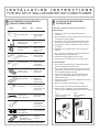
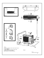
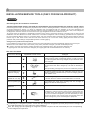
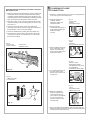
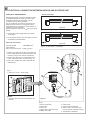
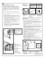
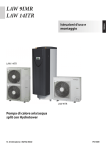
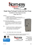
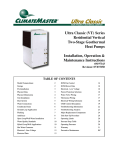
1. ACCESSORIES SUPPLIED WITH THE AIR CONDITIONER
2. LOCATION OF INDOOR AND OUTDOOR UNIT
3. INSTALLATION/SERVICE TOOLS (ONLY FOR R410A PRODUCT)
4. INSTALLATION OF THE INDOOR UNIT
5. CONDENSATE HOSE CONNECTION
6. ELECTRICAL CONNECTION BETWEEN INDOOR AND OUTDOOR UNIT
7. REFRIGERANT TUBING
8. FINAL TASKS
I N S TA L L AT I O N I N S T R U C T I O N S
FOR DCI SPLIT WALL MOUNTED AIR CONDITIONER
1
ACCESSORIES SUPPLIED WITH
THE AIR CONDITIONER
Shape
Name
Qty
Used for
2
LOCATION OF INDOOR AND
OUTDOOR UNIT
Select the location considering the following:
INDOOR UNIT
Mounting plate
1
Remote control
with batteries
1
Remote control
bracket
1
Screws
washer dowels
4
Wall mounting
of the indoor
unit
Operation of
unit
Wall mounting
of the remote
control
Wall mounting
of indoor unit
1. Choose a location which will provide good air
circulation.
2. Do not install the unit near a heat source or where it will
be exposed to direct sunlight.
3. The location must allow convenient electrical wiring.
drainage and tubing connections as shown in fig 3.
4.The appliance must be positioned so that the plug is
accessible.
5 Installation site should provide an easy passage to
outdoors.
6. The unit must be mounted on a strong wall that will
withstand the generated vibrations.
7. Install the mounting plate as shown in fig 5.
8. Install the remote control bracket as shown in fig 4.
Screws dowels
Outdoor unit
drain connector
Mounting pads
2
1
4
Wall mounting
of remote
control bracket
Outdoor unit
water drain
Padding of
outdoor unit
bottom support
OUTDOOR UNIT
1. The location must allow easy servicing and provide
good air circulation as shown in fig 5.
2. The unit may be suspended from a wall by a bracket
(Optional) or located in a free standing position on the
floor (preferably slightly elevated).
3. If the unit is suspended, ensure that the bracket is
firmly connected and the wall is strong enough to
withstand vibrations.
4. Unit location should not disturb neighbors with noise or
exhaust air stream.
5. Place the mounting pads under the unit legs.
Cable ties
4
Securing wires
in the indoor and
outdoor unit
Power input
cable (Optional)
1
Connecting indoor
unit power
Cable terminals
1
Securing of
grounding wire
in the indoor
and outdoor unit
Air purifying
filter (Optional)
2
Cleaning the air
6. Refer to figure 5 for allowed installation distances.
7. When the unit is installed on a wall, install the drain
connector hose and drain plug as shown in fig 1 and fig 2.
Fig.1
1.Bottom of outdoor unit
2.Drain connector
Fig. 2
Fig. 1
Remote control 3
operation
Unit operation
Installation manual
1
Users and
installers
reference
Indoor Unit's Accessories Only for One Unit.
Fig.2
Drain installation
Example
2
950mm
1800mm
80 mm
min
Fig. 3
50 mm
min
50 mm
min
2300 mm
min
To remove
2
100 mm
min
1
100 mm
min
400 mm
min
To attach
Fig. 4
500 mm
min
100 mm
min
NOTE:
Distance between indoor and outdoor units
should be 30m.
Height difference between indoor and
outdoor units should be 15m.
No additional charge is required.
1
Fig. 5
Fig.5
1. Mounting pads (
4)
3
INSTALLATION/SERVICE TOOLS (ONLY FOR R410A PRODUCT)
CAUTION
New Refrigerant Air Conditioner Installation
THIS AIR CONDITIONER ADOPTS THE NEW HFC REFRIGERANT (R410A) WHICH DOES NOT DESTROY OZONE LAYER.
R410A refrigerant is apt to be affected by impurities such as water, oxidizing membrane, and oils because the working pressure
of R410A refrigerant is approx. 1.6 times of refrigerant R22. Accompanied with the adoption of the new refrigerant, the
refrigeration machine oil has also been changed. Therefore, during installation work, be sure that water, dust, former refrigerant,
or refrigeration machine oil does not enter into the new type refrigerant R410A air conditioner circuit.
To prevent mixing of refrigerant or refrigerating machine oil, the sizes of connecting sections of charging port on main unit and
installation tools are different from those used for the conventional refrigerant units. Accordingly, special tools are required for
the new refrigerant (R410A) units. For connecting pipes, use new and clean piping materials with high pressure fittings made for
R410A only, so that water and/or dust does not enter. Moreover, do not use the existing piping because there are some
problems with pressure fittings and possible impurities in existing piping.
Changes in the product and components
In air conditioners using R410A, in order to prevent any other refrigerant from being accidentally charged, the service port
diameter size of the outdoor unit control valve (3 way valve) has been changed. (1/2 UNF 20 threads per inch)
In order to increase the pressure resisting strength of the refrigerant piping, flare processing diameter and
opposing flare nuts sizes have been changed. (for copper pipes with nominal dimensions 1/2 and 5/8)
New tools for R410A
New tools for R410A
Applicable to R22 model
Changes
Gauge manifold
As the working pressure is high, it is impossible to measure the
working pressure using conventional gauges. In order to prevent
any other refrigerant from being charged, the port diameters have
been changed.
Charge hose
In order to increase pressure resisting strength, hose materials
and port sizes have been changed (to 1/2 UNF 20 threads per
inch).
When purchasing a charge hose, be sure to confirm the port size.
Electronic balance for
refrigerant charging
As working pressure is high and gasification speed is fast, it is
difficult to read the indicated value by means of charging cylinder,
as air bubbles occur.
Torque wrench
(nominal dia. 1/2, 5/8)
The size of opposing flare nuts have been increased. Incidentally,
a common wrench is used for nominal diameters 1/4 and 3/8.
Flare tool (clutch type)
By increasing the clamp bar's receiving hole size, strength of
spring in the tool has been improved.
Gauge for projection
adjustment
Used when flare is made by using conventional flare tool.
Vacuum pump adapter
Connected to conventional vacuum pump. It is necessary to use
an adapter to prevent vacuum pump oil from flowing back into
the charge hose. The charge hose connecting part has two ports
-- one for conventional refrigerant (7/16 UNF 20 threads per inch)
and one for R410A. If the vacuum pump oil (mineral) mixes with
R410A a sludge may occur and damage the equipment.
Gas leakage detector
Exclusive for HFC refrigerant.
Incidentally, the "refrigerant cylinder" comes with the refrigerant designation (R410A) and protector coating in the
U.S's ARI specified rose color (ARI color code: PMS 507).
Also, the "charge port and packing for refrigerant cylinder" requires 1/2 UNF 20 threads per inch corresponding
to the charge hose's port size.
4
INSTALLATION OF
THE INDOOR UNIT
INSTALLATION OF THE MOUNTING PLATE
1. Figure 9 shows the location of the mounting plate relative to the
unit size. Refer to one of the drawings, according to your unit
length (marked in square).
REMOVAL AND INSTALLATION OF THE
2. Locate the mounting plate as shown on the wall in a horizontal
FRONT PANEL
position, using a spirit level.
3. Mark the position of the four mounting holes on the wall and drill
four holes to accommodate the dowels.
4. Mount the mounting plate on to the wall by the four screws. Ensure
screws are tightened properly.
1. Open the front panel.
2. Open the terminal cover.
3. After installation of the wires, replace the terminal cover and
close the grille.
Fig.6
1. Lift the grille
2. Screw
3. Terminal
Fig. 8
1
2
3
Fig. 6
PENETRATION OF WALL FOR TUBING
REFRIGERATION TUBE ROUTING
1. There are five possible routes for installing the refrigeration tube as
shown.
2. For route (6), cut the bottom notch in the rear.
3. For routes (5) or (7), cut the side notches in the rear and in the front
panel.
Fig. 7
1. Front
2. Rear
3. Rear outlet
4. Lefthand outlet
5. Lefthand raw outlet
6. Bottom outlet
7. Righthand outlet
1. Mark the location of the hole on either side of the mounting
plate as shown. and drill it at a 5 downward angle, as shown.
2. The hole is drilled at an angle, to prevent condensed or rain
water from penetrating back into the room.
Fig. 9
A. OUTDOOR SIDE
B. INDOOR SIDE
1.Drill 70 mm
2.Wall
4
B
A
5
1
Fig. 9
Fig 87
Fig.
2
SUSPENDING AND RELEASING THE UNIT FROM THE
MOUNTING PLATE
1. Make sure that the refrigerant tubes, electric cables and
condensate water hose are well insulated with closed
cell rubber based insulating tubes (6mm thickness), are
wrapped together with UV stabilized nonadhesive plastic
tape, and are passed through the hole in the wall.
2. Hang the indoor unit on the two hooks that are located
near the top edge of the mounting plate as shown in fig.
10 and fig. 11.
3. Press the lower part of the indoor unit against the
mounting plate until the catches snap into the slots and
lock the indoor unit to the mounting plate.
4. Check the installation by pulling the unit towards you.
5
CONDENSATE HOSE
CONNECTION
1. Attach the condensate drain hose to the corrugated hose
in the rear groove of the indoor unit.
2. Wrap the drain hose
together with the
refrigerant tubes and
electrical cables.
3. Ensure that the
condensate drain hose is
at all points installed in a
downward slope
manner.
5. To release the unit from the mounting plate, lift up the
unit and then pull the unit towards you, to ensure that
the hooks are locked.
Fig.10
1.Indoor unit
2.Snap catches
2
1
2
3
Fig. 12
Fig.13
1.Trap
2.U-bend
3.End immersed in water
3.Top hooks
4.Bottom hooks
1
Fig.12
1.Drain hose
2.Clamp
3.Downward slope
4. When installing the drain
hose avoid traps and Ubends. The end of the
drain hose should not be
immersed in water.
3
1
3
2
Fig. 13
Fig.14
1.Electric cable
2.Refrigerant tubing
3.Condensate drain hose
4.UV stabilized
nonadhesive plastic tape
4
Fig. 10
5. For a lefthand outlet, lay
the drain hose on the
bottom of the indoor unit
rear groove.
Fig. 14
1
2
Fig.11
1.Mounting plate
2.Lower hook
3
4
1
Fig.15
1.Vent
2.Downward drain
3.Water drain hose
2
Fig. 11
6.When the installation
location requires long
horizontal sections, a
vent must be provided at
the top of the hose to
prevent overflow of the
unit drain pan.
1
Fig. 15
3
2
7.Upon completing the installation, test the water drain by
pouring at least two liters of water into the unit drain pan.
Check that the water drains off.
6
ELECTRICAL CONNECTION BETWEEN INDOOR AND OUTDOOR UNIT
Power input cable
ELECTRICAL REQUIREMENTS
Electrical wiring and connections should be made
by qualified electricians and in accordance with
local electrical codes and regulation. The air
conditioner units must be grounded.
The air conditioner unit must be connected to an
adequate power outlet from a separate branch
circuit protected by a time delay circuit breaker, as
specified on unit's nameplate.
Voltage should not vary beyond 10% of the rated
voltage.
8
8
100
40
Fig. 17a
Cable between indoor and outdoor units
L
1. Connect the power supply cable to the indoor
unit of WNG.
2. To connect the indoor unit to the outdoor unit use
the following electrical cables.
8
8
100
40
A
Electrical connections:
Power input cable:
B
Fig. 17b
2.5 mm2
3 wires
Cable between
Indoor and outdoor units: 4 wires
30 m
Fig.17 A. OUTDOOR B. INDOOR
2.5 mm
2
3. Prepare the cable ends for the power input and
for the cables between outdoor and indoor units
as shown in figure 17a and 17b respectively.
4. Connect the cable ends to the terminals of the
indoor and outdoor units, as shown in fig. 18.
1
5. Secure the multiple wire power cable with the
cable clamps.
3
ESF-PWR
COOL
ESF-EN
HEAT
RESET
MODE
5/C 4/L N L
2
Fig.16
1. Terminal 2. Cover 3. Cable clamp
4
8
N
4/L 5/C
7
A
B
6
Fig. 16
5
NOTES:
1. The wire color code can be selected by the
installer.
Fig. 18
Fig.18
1. Indoor unit terminal
2. Ground wire.
3. Indoor coil.
4. Power cable in the indoor side.
5. Multiple wire cable.
6. Cable clamp.
7. Outdoor unit wire terminal.
8. Power cable in the outdoor side
(only for outdoor unit power supply)
A. OUTDOOR B. INDOOR
7
Tightening
torques of unions
and valve caps:
REFRIGERANT TUBING
CONNECT THE INDOOR TO THE OUTDOOR UNIT
The indoor unit contains a small quantity of nitrogen. Do
not unscrew the nuts from the unit until you are ready to
connect the tubing. The outdoor unit is supplied with
sufficient refrigerant charge (R410A). Refer to outdoor unit
nameplate.
Fig. 20
NOTE: Use refrigeration R410A type copper tubing only.
2. Use tubing diameter that corresponds to the tubing
diameter of the indoor and outdoor units. Note that the
liquid and suction tubes have different diameters. (See
tube size, torque tightening table.)
3. Place flares nuts on tube ends before preparing them
with a flaring tool. Use the flare nuts that are mounted
on the supplied outdoor and indoor units.
4. Connect the all ends of the tubing to the indoor and
outdoor units. Notice the sign. All ends should
correspond one by one.
5. Insulate each tube separately, and their unions, with at
least 13 mm thick of insulation. Wrap the refrigerant
tubing, drain hose and electric cables together with a
vinyl tape (UV protected).
1
2
Caution!
When unscrewing the
valve caps, do not stand
in front of them or the
spindles at any time, as
the system is under
pressure.
3
4
Fig. 19
Fig. 19
1.INDOOR UNIT
2.Liquid tube (small dia.)
3.Suction tube (large dia.)
4.Plugs
5.Flare nuts
6.Tubing between units
7.Suction tube
8.Liquid tube
9.OUTDOOR UNIT
10.Flare nuts
11.Liquid valve (small)
12.Suction valve (larger)
TORQUE
30-35 N.M.
50-54 N.M.
75-78 N.M.
80-100 N.M.
Fig. 21
1
To prevent crushing, bend tubes using a bending tool.
1. Open the valve cover.
TUBE SIZE
Liquid line 3/8"
Suction line 1/2"
Suction line 5/8"
Suction line 3/4"
Fig. 22
1
2
2
3
3
Fig.20
1.Wrench
2.Torque wrench
3.Union
Fig. 21
To prevent refrigerant
leakage, coat the flared
surface with
refrigeration oil
Fig. 22
1.Suction valve
2.Service port
3.Liquid valve
EVACUATION OF THE REFRIGERATION TUBES AND THE
INDOOR UNIT
After connecting the unions of the indoor and outdoor units,
purge the air from the tubes and indoor unit as follows:
1. Connect the charging hoses with a push pin to the low side
of the charging set and the service port of the suction valve.
Be sure to connect the end of the charging hose with the
push pin to the service port.
2. Connect the center hose of the charging set to a vacuum
pump.
3. Turn on the power switch of the vacuum pump, turn off the
high side switch and make sure that the needle in the gauge
moves from 0 MPa (0cm Hg) to -0.1 MPa (-76cm Hg). Let
the pump run for fifteen minutes.
4. Close the valve of the low side of the charging set and turn
off the vacuum pump. Note that the needle in the gauge
should not move after approximately five minutes.
5. Not any problem for five minutes, turn on the power switch of
the vacuum pump and open the valve of the low side of the
charging set.
6. Disconnect the charging hose from the vacuum pump and
from the service ports of the suction valve.
7. Tighten the service port caps of suction valve.
8. Redo 1 to 7 for other indoor units.
9. Remove the valve caps from all valves, and open them
using a hexagonal Allen wrench.
10. Remount valve caps onto all of the valves.
11. Check for gas leaks from all the connecting position. Test
with electronic leak detector or with a sponge immersed for
soapy water for bubbles.
NOTE
For additional
charge of various
tubing lengths,
refer to outdoor
unit nameplate.
Fig. 23
Fig. 23
1. Charging set
2. Vacuum pump
3. OUTDOOR UNIT
4. Service valve
5. Cap
6. Suction valve
7. Service valve*
8. Cap
9. Liquid valve
10. INDOOR UNIT
11. Suction flare connection
12. Liquid flare connection
*In some models only
),1$/ 7$6.6
&KHFN DOO YDOYH FDSV DQG HQVXUH WKDW WKH\ KDG WLJKWHQHG SURSHUO\ &ORVH WKH YDOYH FRYHU
)LOO JDSV RQ WKH ZDOO EHWZHHQ KROH VLGHV DQG WXELQJ ZLWK VHDOHU
$WWDFK ZLULQJ DQG WXELQJ WR WKH ZDOO ZLWK FODPSV ZKHUH QHFHVVDU\
2SHUDWH WKH XQLW IRU QR OHVV WKDQ PLQXWHV DW KHDWLQJ RU FRROLQJ PRGH
([SODLQ ILOWHU UHPRYDO FOHDQLQJ DQG LQVWDOODWLRQ
2SHUDWH WKH DLU FRQGLWLRQHU WRJHWKHU ZLWK WKH FXVWRPHU DQG H[SODLQ DOO IXQFWLRQV
*LYH WKH RSHUDWLQJ DQG LQVWDOODWLRQ PDQXDOV WR WKH FXVWRPHU
$QDOOSROHGLVFRQQHFWLRQVZLWFKKDYLQJDFRQWDFWVHSDUDWLRQRIDWOHDVWPPLQDOOSROHVVKRXOGEHFRQQHFWHGLQIL[HGZLULQJ