1
5.10.4 Battery replacement and wiring
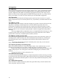
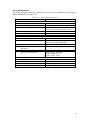
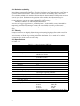
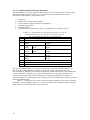
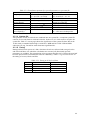
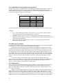
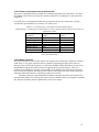
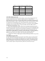
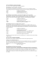
The batteries are organized, first in series of several cells and second in several series in
parallel. In Table 5.10.4 the number of batteries per series and the number of series in parallel
are given for the various buoy models.
Table 5.10.4. Battery type, organization and total number
of batteries and total energy content per buoy model.
Buoy model
Battery type Cells per Series in Total
Total energy
series
parallel number content (Wh)
WR-SG 0.9 m
RC25G
13
2
26
6500
WR-SG 0.7 m
RC25G
13
1
13
3250
DWR-MkIII 0.9 m RC20B
15
3
45
9000
DWR-MkIII 0.7 m RC20B
15
1
15
3000
DWR-G 0.9 m
RC25G
13
5
65
16250
DWR-G 0.7 m
RC25G
16
2
32
8000
DWR-G 0.4 m
RC25GS
4
1
4
1000
DWR-G 0.4 m
RC16R
4
1
4
840
The battery replacement procedure is nearly the same for all buoys. Also consult
subsection 5.11.5, setbat command, to enter the amount of energy into the buoy’s
microcomputer. To access the batteries within the hull the hatchcover must be removed first of
course. Removal of the HF/LED whip antenna is not obligatory but will make handling the
hatchcover more comfortable. Take out the drying agent bags and unscrew the wing nuts
retaining the plywood boards. Now remove the foam cover on top of the batteries. Disconnect
the battery wiring and take out the used batteries. Place the new batteries starting with battery
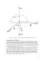
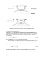
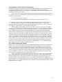
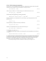
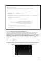
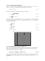
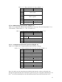
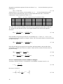
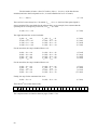
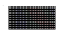
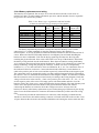
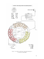
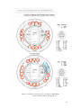
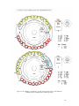
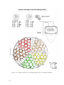
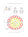
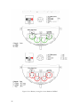
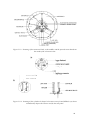
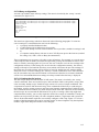
A1 in clockwise direction and interconnect the batteries. Figures 5.10.2 through 5.10.9 show the
battery numbering, wiring and grouping for all buoys. Cells in one series are sequentially
numbered 1, 2, 3, etc. and consecutive series are labelled A, B, C, etc. Use connection wires of
the indicated colour for each series. Connect the black leads of the buoy’s main hatchcover
cable to the positive pole of each series and the respectively coloured leads to the negative pole.
The connection wires are arranged in such a way that a marginal magnetic field is generated by
the currents. This is to minimize the disturbance of the fluxgate compass. It is therefore essential
that the connection wires are always routed exactly according to the wiring diagram. Check the
voltage of each series in the test box. “+Bat” is the positive pole of all series. “A”, “B”, “C”, etc.
are the negative poles of the series. Fill empty spaces with foam rubber and also cover the
batteries with a (dry) foam cover. Apply and fasten the plywood boards. The cord of battery and
sensor wires must pass between the inside of the plywood boards and the hull. Before
connecting the hatchcover connector check the voltages once more. Always close the
hatchcover directly after battery replacement to prevent the taking up of moisture by the drying
agent. Leave the main hatchcover connector disconnected if the buoy will be stored for a long
time.
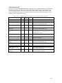
In some buoy models the main hatchcover connector (cable and plug) is attached to the
hatchcover electronics unit and the mating connector is located in the hull on the test box. Lack
of space between the electronics unit and the aluminium can housing the sensors motivates this.
88