1
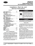
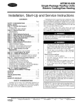
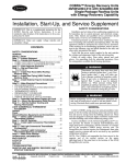
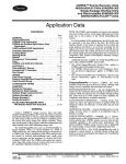
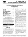
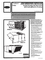
Product
Data
WEATHERMAKER® 48TM004-028
WEATHERMASTER® 48HJ004-028
Single-Package Rooftop Units
Gas Heating/Electric Cooling
3 to 25 Nominal Tons
48HJ004-014
48TM004-014
48HJ015,017
48TM016-025
Heat Options
• Exclusive integrated gas control
board with diagnostics
• Alumagard™ heat exchanger coating
• Induced-draft fan for gas combustion
• Tubular, dimpled heat exchangers
• Natural gas
• LP conversion kits
• Low NOX (size 004-006 only)
• Optional stainless steel heat
exchangers.
48TM028
Copyright 2004 Carrier Corporation
Standard-Efficiency (TM) units
meet minimum ASHRAE 90.1 energy efficiency requirements. HighEfficiency (HJ) units well exceed
ASHRAE 90.1 energy efficiency
requirements. Gas heating with
electric cooling rooftop units offer:
• Pre-painted galvanized steel cabinet
for long life and quality appearance
• Commercial strength base rails with
built-in rigging capability
• Convertible design for vertical or horizontal supply/return (004-014 only)
• Non-corrosive, sloped condensate
drain pan, meets ASHRAE 62 (IAQ)
• Two-inch return-air filters
• A wide assortment of factory-installed
options available, including high-static
drives that provide additional
performance range
• Optional factory-installed COBRA™
energy recovery unit (option on
48HJ004-014 units only)
• Factory-installed PremierLink™
digital communicating controls
→ • Factory-installed optional gear driven
EconoMi$er IV (vertical return for
sizes 004-012 only) for use with
standard rooftop unit controls
(includes CO2 sensor control
capability)
• Factory-installed optional gear driven
EconoMi$er2 (vertical return only) for
use with PremierLink DDC controls
(includes 4 to 20 mA actuator for
demand control ventilation)
• Humidi-MiZer™ adaptive dehumidification system (48HJ004-014)
• MoistureMi$er™ dehumidification
package
905
Form 48H,T-6PD
Table of contents
Page
Features/Benefits . . . . . . . . . . . . . . . . . . . . . . . . . . . . . . . . . . . . . . . . 2-5
Model Number Nomenclature. . . . . . . . . . . . . . . . . . . . . . . . . . . . . . 6-10
ARI Capacity Ratings . . . . . . . . . . . . . . . . . . . . . . . . . . . . . . . . . . . 11-17
Options and Accessories . . . . . . . . . . . . . . . . . . . . . . . . . . . . . . . . 18-27
48TM
Physical Data . . . . . . . . . . . . . . . . . . . . . . . . . . . . . . . . . . . . . . . . . . . 28-33
Base Unit Dimensions . . . . . . . . . . . . . . . . . . . . . . . . . . . . . . . . . . . . . 34-39
Accessory Dimensions. . . . . . . . . . . . . . . . . . . . . . . . . . . . . . . . . . . . . 40-45
Selection Procedure . . . . . . . . . . . . . . . . . . . . . . . . . . . . . . . . . . . . . . 46,47
Performance Data . . . . . . . . . . . . . . . . . . . . . . . . . . . . . . . . . . . . . . . 48-93
Electrical Data . . . . . . . . . . . . . . . . . . . . . . . . . . . . . . . . . . . . . . . . . . 94-98
Typical Wiring Schematics . . . . . . . . . . . . . . . . . . . . . . . . . . . . . . . . . 99-104
Typical Piping and Wiring . . . . . . . . . . . . . . . . . . . . . . . . . . . . . . . . 105,106
Guide Specifications . . . . . . . . . . . . . . . . . . . . . . . . . . . . . . . . . . . . 107-118
48HJ
Physical Data . . . . . . . . . . . . . . . . . . . . . . . . . . . . . . . . . . . . . . . . . 119-127
Base Unit Dimensions . . . . . . . . . . . . . . . . . . . . . . . . . . . . . . . . . . . 128-135
Accessory Dimensions. . . . . . . . . . . . . . . . . . . . . . . . . . . . . . . . . . . 136-143
Selection Procedure . . . . . . . . . . . . . . . . . . . . . . . . . . . . . . . . . . . . 144-146
Performance Data . . . . . . . . . . . . . . . . . . . . . . . . . . . . . . . . . . . . . 147-219
Electrical Data . . . . . . . . . . . . . . . . . . . . . . . . . . . . . . . . . . . . . . . . 220-230
Typical Wiring Schematics . . . . . . . . . . . . . . . . . . . . . . . . . . . . . . . . 231-241
Typical Piping and Wiring . . . . . . . . . . . . . . . . . . . . . . . . . . . . . . . . 242,243
Guide Specifications . . . . . . . . . . . . . . . . . . . . . . . . . . . . . . . . . . . . 244-267
Controls . . . . . . . . . . . . . . . . . . . . . . . . . . . . . . . . . . . . . . . . . . . 268-279
Application Data . . . . . . . . . . . . . . . . . . . . . . . . . . . . . . . . . . . . . 280-284
Index . . . . . . . . . . . . . . . . . . . . . . . . . . . . . . . . . . . . . . . . . . . . . . . . . . 285
2
Features/Benefits
Every compact one-piece
unit arrives fully assembled,
charged, tested, and ready to
run.
48 Series — gas heat models
All ignition components are contained
in the compact IGC (integrated gas
controller) which is easily accessible for
servicing. The IGC control board, designed and manufactured exclusively
for Carrier rooftop units, provides
built-in diagnostic capability. An LED
(light-emitting diode) simplifies troubleshooting by providing visual fault notification and system status confirmation.
The IGC also contains an exclusive
anti-cycle protection for gas heat operation. After 4 continuous cycles on the
unit high-temperature limit switch, the
gas heat operation is disabled, and an
error code is issued. This feature greatly improves reliability of the rooftop
unit.
The IGC also contains burner control logic for accurate and dependable
gas ignition. The LED is visible without
removing the unit control box access
panel. This LED fault-notification system reduces service person troubleshooting time and minimizes service
costs. The IGC also maximizes heating
efficiency by controlling evaporator-fan
on and off delays.
Tubular, dimpled gas heat exchangers optimize heat transfer for improved
efficiency. The tubular design permits
hot gases to make multiple passes
across the path of the supply air. The
dimpled design creates a turbulent gas
flow to maximize heating efficiency.
The efficient in-shot burners and
all ignition components are contained
in an easily removable, compact
assembly.
The California Air Quality Management Districts NOx requirement of
40 nanograms/joule or less is met on
004-006 size Low NOx models.
The extra thick Alumagard™ heat
exchanger coating provides corrosion
resistance and ensures long life
(optional stainless steel heat exchangers are available).
The unsightly appearance of flue
stacks is eliminated and the effects of
wind on heating operations are diminished by the induced draft combustion
system. The inducer fan draws hot
combustion gas through the heat
exchanger at the optimum rate for the
most effective heat transfer. The heat
exchanger operates under negative
pressure, preventing flue gas leakage
into the indoor supply air.
During the Heating mode, the
evaporator-fan relay automatically
starts the evaporator fan after the heat
exchanger warms up to a suitable
temperature. The 30-second fan delay
prevents cold air from entering the
supply duct system when the conditioned space is calling for heat to
maximize efficiency.
The direct-spark ignition system
saves operating expense when compared to pilot ignition systems. No
crossover tube is required, therefore no
sooting or pilot fouling problems can
occur.
All standard units are designed for
natural gas, but an accessory LP (liquid
propane) conversion kit is available.
All units have a flame rectification
sensor to quickly sense the burner
flame and ignite burners almost immediately. Fast shutdown is a certainty
since the sensor reacts quickly to any
flame outage or system failure. In the
event of a shutdown, an error code is
issued at the IGC board.
Safety is also assured due to the
heating safety controls which will shut
down the unit if there is a problem. If
excessive temperatures develop, limit
switches shut off the gas valve. After
4 continuous short cycles of the hightemperature limit switch, the IGC
board locks out the gas heat cycle to
prevent any further short cycles. This
safety feature is provided exclusively on
Carrier rooftop units. The rollout
switch also deenergizes the gas valve in
the event of a flame rollout.
Quiet, efficient operation and
dependable performance
Compressors have vibration isolators
for quiet operation. Efficient fan and
motor design permits operation at low
sound levels.
Unit sizes 008-028 offer lower utility
costs through part-load operation using 2 or 3 stages of cooling.
Quiet and efficient operation is provided by belt-driven evaporator fans
(standard on all units over 5 tons). The
belt-driven evaporator-fan is equipped
with variable-pitch pulleys which allow
adjustment within the rpm ranges of
the factory-supplied pulleys.
Increased operating efficiency is
achieved through computer-designed
coils featuring staggered internally
enhanced copper tubes. Fins are
ripple-edged for strength, lanced, and
double waved for higher heat transfer.
Durable, dependable
construction
Designed for durability in any climate,
the weather-resistant cabinets are constructed of galvanized steel and bonderized, and all exterior panels are coated with a prepainted baked enamel finish. The paint finish is non-chalking,
and is capable of withstanding ASTM
(American Society for Testing and Materials) B117 500-hour Salt Spray
Test. All internal cabinet panels are
primed, permitting longer life and a
more attractive appearance for the
entire unit.
In addition, all size 004-014 units
are designed with a single, continuous
top piece to eliminate any possible
leaks at seams or gasketing. Totally enclosed condenser-fan motors and permanently lubricated bearings provide
additional unit dependability.
Easy installation and
conversion
All units are shipped in the vertical duct configuration for fit-up to
standard roof curbs. The contractor
can order and install the roof curb early
in the construction stage, before decisions on size requirements are made.
All units feature a base rail design
with forklift slots and rigging holes for
easier maneuvering. Durable packaging protects all units during shipment
and storage.
The units can be easily converted
from a vertical to a horizontal duct configuration by relocating the panels supplied with the unit (size 004-014 only).
To convert 004-014 units from
vertical to horizontal discharge, simply
relocate 2 panels. The same basic unit
can be used for a variety of applications and can be quickly modified at
the jobsite.
To convert 015-028 units from
vertical to horizontal discharge, use the
optional horizontal supply/return
adapter roof curb (48HJ015,017 and
48TM016-028) or accessory conversion kit (48HJ020-028).
Convenient duct openings in the
unit basepans permit side-by-side or
concentric duct connections (see
Application data section) without requiring internal unit modification.
NOTE: On units using horizontal supply and return, the accessory barometric relief or power exhaust MUST be
installed on the return ductwork.
Thru-the-bottom service connection capability comes standard with
the rooftop unit to allow power and
control wiring and gas connections to
be routed through the unit’s basepan,
thereby minimizing roof penetrations
(to prevent water leaks). (Thru-thebottom gas connection requires thruthe-bottom accessory kit.) Power, gas
and control connections are made on
the same side of the unit to simplify
installation.
The non-corrosive sloped condensate drain pan (size 004-014)
permits either an external horizontal
side condensate drain (outside the roof
curb) or an internal vertical bottom
drain (inside the roof curb). Both
options require an external, fieldsupplied P-trap.
Standard 2-in. throwaway filters
are easily accessed through a removable panel located above the air intake
hood. No tools are required to change
unit filters.
Belt-driven evaporator-fan motors
(optional on TM units under 6 tons)
allow maximum on-site flexibility without changing motors or drives.
Low voltage wiring connections
are easily made thanks to the large terminal board which is located for quick,
convenient access.
In addition, color-coded wires permit
easy tracing and diagnostics.
Proven compressor reliability
Design techniques feature computerprogrammed balance between compressor, condenser, and evaporator.
Carrier-specified hermetic compressors are equipped with compressor
overcurrent and overtemperature protection to ensure dependability.
3
Features/Benefits (cont)
All units have Carrier’s exclusive
Acutrol™ (004-014) or TXV (thermostatic expansion valve) metering device
(015-028) which precisely controls refrigerant flow, preventing
slugging and flood-back, while maintaining optimum unit performance. Refrigerant filter driers are standard.
→ Integrated economizers and
outdoor-air dampers
Available as options or accessories,
economizers and manual outdoor-air
dampers introduce outdoor air which
mixes with the conditioned air, improving indoor-air quality and often reducing energy consumption.
During a first stage call for cooling, if
the outdoor-air temperature is below
the economizer control changeover
set point, the mixed-air sensor modulates the economizer outdoor-air damper open to take advantage of free cooling provided by the outside air. When
second-stage cooling is called for, the
compressor is energized in
addition to the economizer. If the
outdoor-air temperature is above the
changeover set point, the first stage
of compression is activated and the
economizer damper stays at minimum
position.
Accessory upgrade kits allow for
control by differential dry-bulb temperature (outdoor vs return), outdoor air
enthalpy changeover, or more precise
differential enthalpy control.
Units can be equipped with different
economizer options to meet specific
controls applications. The factoryinstalled or field-installed EconoMi$er IV
and EconoMi$er2 are available. The
EconoMi$er IV is used with the standard rooftop unit controls and includes
an industry standard, stand-alone,
solid-state controller. The control can be
used with a CO2 sensor for DCV (demand control ventilation) operation. For
direct digital control (DDC) applications,
the EconoMi$er2 can be operated using
PremierLink controls or a third party
controller. The EconoMi$er2 includes
4 to 20 mA actuator capability for demand control ventilation applications.
All economizers incorporate a parallel blade, gear-driven damper system
for efficient air mixing and reliable control. In addition, the standard damper
actuator includes a spring return to
provide reliable closure on power loss.
The economizers for sizes 004-014 are
4
equipped with up to 100% barometric
relief capability for high outdoor airflow operations. Economizers for unit
sizes 004-014 are available, factoryinstalled, for vertical return only. Economizers for unit sizes 015-028 are
compatible for vertical or horizontal return. An optional field-installed barometric relief package is available for
size 015-028 units.
In addition, single-stage power
exhaust is available as a field-installed
accessory for EconoMi$er IV to help
maintain proper building pressure.
For units without economizer, yearround ventilation is enhanced by an optional manual outdoor-air damper. On
004-014 units, a 25% or 50% manual
damper is available as a field-installed
accessory. Unit sizes 015-028 are
equipped with a manual 25% damper.
Service options (48HJ004017 and 48TM004-028 units
only)
Servicing a rooftop unit has never been
easier with the factory-installed service
options for these rooftop units. These
options include the following:
• Hinged access panels are provided
for the filter/indoor-fan motor,
compressors, evaporator fan, and
control box areas. Quick access to
major components is accomplished
by simply unlatching and swinging
open the various panels. Each
hinged panel is permanently
mounted to the unit, thereby eliminating the concern of a dropped or
wind-blown panel puncturing delicate roof materials. The 4 extended
access panels are also equipped with
‘‘tie back’’ retaining devices to hold
the door in the open position while
servicing the unit.
• An external, covered, 115-v Ground
Fault Interrupt (GFI) receptacle is
provided as a convenient power
source for drills, lights, refrigerant
recovery units, or other electrical
service tools. A factory-supplied step
down transformer is connected to
the “load” side of the unit main
power connection (size 004-014).
For sizes 015-028, connect the outlet to a field-supplied and properly
fused branch circuit power supply.
• Slide out “motor-drive-blower”
reduces service time (only on
48HJ017).
905
• An integral non-fused disconnect
switch within the rooftop unit
reduces installation time, labor and
material costs. Safety is assured by
an interlock which prevents access
to the control box unless the switch
is in the OFF position. In addition,
the externally mounted handle
incorporates power lockout capability to further protect service
personnel.
Carrier PremierLink™ controls
add reliability, efficiency, and
simplification (48HJ004-017
and 48TM004-028 units only)
The PremierLink direct digital controls
can be ordered as a factory-installed
option or as a field-installed accessory.
Designed and manufactured exclusively
by Carrier, the controls can be used to
actively monitor and control all modes
of operations, as well as monitor the
following diagnostics and features: unit
number, zone temperature, zone set
point, zone humidity set point, discharge air temperatures, fan status,
stages of heating, stages of cooling,
damper position, outdoor-air temperature, outdoor humidity level, filter
status, fire shutdown status, IAQ (indoor air quality) set point, enthalpy status, differential enthalpy status, heat/
cool lockout, cfm set point, preoccupancy purge, economizer controls
and early morning warm-up.
This controller has a 38.4K baud
communications capability and is compatible with ComfortLink™ controls,
CCN (Carrier Comfort Network®) and
ComfortVIEW™ software. The Scrolling Marquee and Navigator™ display
are optional tools that can be used for
programming and monitoring the unit
for optimal performance. The addition
of the Carrier CO2 sensor in the conditioned space provides ASHRAE
(American Society of Heating, Refrigeration, and Air Conditioning Engineers) 62-99 compliance and Demand
Control Ventilation.
The PremierLink peer-to-peer, Internet ready communicating control is designed specifically for Constant Volume
(CV) and Variable Volume and Temperature (VVT®) applications. This comprehensive controls system allows all
Carrier 3 to 25 ton rooftops with a
3-wire communications bus to be daisy
chained together on a roof to create a
fully functional HVAC (heating,
ventilation, and air conditioning) automation system.
neutral air for maximum dehumidification operation.
Indoor-air quality (IAQ) begins
with Carrier rooftops
Exclusive MoistureMi$er™
dehumidification package
(48HJ015,017 and 48TM016028 only)
Sloped condensate pans minimize
biological growth in rooftop units in
accordance with ASHRAE Standard
62. Two-inch filters with optional dirty
filter indicator switch provide for
greater particle reduction in the return
air. The face-split evaporator coils
improve the dehumidification capability of standard units, maximize building
humidity control.
Optional proportional reacting CO2
sensor is available with the EconoMi$er IV outdoor air damper option/
accessory to aid the IAQ benefits.
Humidi-MiZer™ adaptive
dehumidification system
(48HJ004-014)
Carrier’s Humidi-MiZer adaptive dehumidification system is an all-inclusive
factory-installed option that can be
ordered with any Weathermaster®
48HJ004-014 rooftop unit to meet
the demand for providing a flexible and
high performing solution to accommodate all of these design related issues.
This system expands the envelope of
operation of Carrier’s Weathermaster
48HJ004-014 rooftop products to
provide unprecedented flexibility to
meet year-round comfort conditions.
The Humidi-MiZer adaptive dehumidification system has the industry’s only
dual dehumidification mode setting.
The Humidi-MiZer system includes two
new modes of operation. The Weathermaster 48HJ004-014 rooftop coupled with the Humidi-MiZer system is
capable of operating in normal design
cooling mode, subcooling mode, and
hot gas reheat mode. Normal Design
Cooling mode is when the unit will
operate under its normal sequence of
operation by cycling compressors to
maintain comfort conditions. Subcooling mode will operate to satisfy part
load type conditions when the space
requires combined sensible and a
higher proportion of latent load control. Hot Gas Reheat mode will operate when outdoor temperatures
diminish and the need for latent capacity is required for sole humidity control.
Hot Gas Reheat mode will provide
The MoistureMi$er dehumidification
package is a result of recent advances
by Carrier in controlling comfort levels.
This factory-installed option significantly improves the dehumidification capability of the rooftop unit and helps control humidity levels in the building.
This option provides increased dehumidification by cooling the hot liquid refrigerant leaving the condenser coil. The
MoistureMi$er package consists of a
subcooling coil located on the leaving-air
side of the evaporator coil. The location
of this coil in the indoor airstream enhances the latent capacity of the
48HJ015 and 017 and 48TM016-028
units by as much as 40%. Many buildings suffer from humidity damage or
poor indoor air quality due to humid
conditions. The improved latent capacity
provided by the MoistureMi$er option
reduces the building’s humidity, eliminating potential property damage and making the space more comfortable.
The MoistureMi$er option is the
ideal IAQ option for hot and humid
regions. The operation of the
MoistureMi$er package can be controlled by a field-installed, wall mounted humidistat or Thermidistat™ device.
The circuit activates only when needed
(using the accessory humidistat) as opposed to some dehumidification systems that operate continuously. The
humidistat can be set for any humidity
level between 20% and 80% relative
humidity.The Thermidistat device can
be set for any humidity level between
50% and 90% relative humidity.
COBRA™ energy recovery
units (sizes 004-014 only)
Carrier’s factory-installed optional
COBRA units recover energy from the
building exhaust air and pre-condition
ventilation air for the rooftop unit during winter and summer operation.
These units are designed to satisfy the
higher ventilation requirements and
other building codes while minimizing
energy costs.
Factory installation of the 62AQ
section provides the benefit of reduced
field-installation time, single point
power connections, and the assurance
of a factory test for the complete
COBRA unit. The COBRA energy
recovery section requires less maintenance than other energy recovery
systems and can be serviced by any
qualified refrigeration technician.
The COBRA energy recovery units
utilize Carrier’s high-efficiency
48HJ004-014 rooftop units and provide 3 to 121/2 tons of cooling capacity with the capability to pre-condition
600 to 3000 cfm of outdoor air.
Indoor-air quality (IAQ) generally refers to the level of pollutants inside a
building. These pollutants include cigarette smoke, carbon dioxide exhaled by
occupants, radon gas, car exhaust,
paint fumes, and odors.
Concern over increased indoor air
pollutants has been spurred by several
issues: 1) changes in new building
construction methods and retrofit of
older buildings have reduced air
infiltration rates; 2) Synthetic materials
release airborne particles, odors,
and chemicals; and 3) HVAC systems
that bring in minimal fresh air.
In 1989, IAQ concerns caused
ASHRAE to recommend increased
ventilation for all public buildings.
Simply introducing fresh air into a
building, however, is not always
practical or cost effective. Additional
ventilation can overload HVAC
systems and increase energy costs.
Carrier’s COBRA energy recovery
unit solves this dilemma by providing
increased fresh air while keeping
increased costs to a minimum. In
addition, the COBRA energy recovery
unit helps reduce humidity levels,
which helps to prevent deterioration of
building materials and retards the
growth of mold and mildew.
The COBRA energy recovery unit
provides the best solution to retaining
the energy-conserving benefits of today’s tighter building construction
while improving indoor-air quality.
5
Model number nomenclature
48TM004-014
Example:
48 TM
D
006
P
M
F
6
-
-
HA
48 – Packaged Rooftop
Electric Cooling/
Natural Gas Heat
Factory-Installed Options†
Voltage
1 – 575-3-60
3 – 208/230-1-60
5 – 208/230-3-60
6 – 460-3-60
TM – Constant Volume, Standard Efficiency
Heat Options:
49 States
D – Low Heat
E – Medium Heat
F – High Heat
California Compliant
L – Low NOx Low Heat
M – Low NOx Medium Heat
N – Low NOx High Heat
Capacity Nominal-Tons
004 – 3 Tons
005 – 4 Tons
006 – 5 Tons
007 – 6 Tons
008 – 7-1/2 Tons
009 – 8-1/2 Tons
012 – 10 Tons
014 – 12-1/2 Tons
Coil Protection Options (fin/tube)
– – Al/Cu Cond & Evap (Standard Unit)
B – Cu/Cu Cond & Evap
C – Cu/Cu Cond & Al/Cu Evap
F – E-Coat Al/Cu Cond & Al/Cu Evap
G – E-Coat Cu/Cu Cond & Al/Cu Evap
V – Al/Cu Pre-Coat Cond Fin & Al/Cu Evap
Indoor Motor Options
– – Standard Motor & Drive
A – Alternate Motor
M – High-Static Indoor Motor
Controls and Sensors
– – None
N – Novar ETM3051 Control*
P – PremierLink™ DDC Control
Quality Assurance
Al
Cu
DDC
FIOP
—
—
—
—
LEGEND
Aluminum
Copper
Direct Digital Controls
Factory-Installed Option
*Contact factory for availability and application information.
†Refer to 48TM Price Pages, Quote Builder, or contact your local Carrier representative for FIOP code table.
6
Certified to ISO 9001:2000
ARI* capacity ratings
ARI* CAPACITY RATINGS — 48TM004-014
UNIT
48TM
004
005
006
007
008
009
012
014
db
EER
IPLV
SEER
wb
—
—
—
—
—
NOMINAL
TONS
3
4
5
6
71/2
81/2
10
121/2
NET COOLING
CAPACITY (Btuh)
35,000
47,000
57,000
71,000
88,000
100,000
114,000
136,000
TOTAL
kW
4.0
5.3
6.7
7.0
8.7
9.9
11.3
14.3
SEER†
EER**
10.0
10.0
10.0
—
—
—
—
—
8.7
8.8
8.5
10.1
10.1
10.1
10.1
9.5
SOUND RATING
(decibels)
81
81
81
80
82
82
84
86
IPLV††
N/A
N/A
N/A
N/A
10.5
10.4
11.0
9.7
2. ARI ratings are net values, reflecting the effects of circulating fan heat.
3. Ratings are based on:
LEGEND
Dry Bulb
Energy Efficiency Ratio
Integrated Part-Load Values
Seasonal Energy Efficiency Ratio
Wet Bulb
*Air Conditioning and Refrigeration Institute.
†The SEER values shown for sizes 004, 005, and 006 are for units with the
optional belt drive motors; SEER rating for these units with the standard direct
drive motor is 9.7.
**ARI does not require EER ratings for units with capacity below 65,000 Btuh.
For these units, the EER rating at ARI standard conditions is provided for information only.
††The IPLV applies only to two-stage cooling units.
NOTES:
1. Rated in accordance with ARI Standards 210-94 or 360-93.
Cooling Standard: 80 F db, 67 F wb indoor entering-air temperature and
95 F db air entering outdoor unit.
IPLV Standard: 80 F db, 67 F wb indoor entering-air temperature and 80 F
db outdoor entering-air temperature.
4. All 48TM004-014 units are in compliance with ASHRAE 90.1 2001 Energy
Standard for minimum SEER and EER requirements. Refer to state and
local codes or visit the following website: http://solstice.crest.org/efficiency/
bcap to determine if compliance with this standard pertains to a given geographical area of the United States.
HEATING CAPACITIES AND EFFICIENCIES — 48TM004-014
208/230-1-60 — SINGLE-STAGE GAS HEAT
UNIT
48TM
E004
F004
D005
E005
F005
D006
E006
F006
INPUT CAPACITY
1st Stage
2nd Stage
74,000
—
115,000
—
74,000
—
115,000
—
150,000
—
74,000
—
115,000
—
150,000
—
UNIT
48TM
M004
N004
L005
M005
N005
L006
M006
N006
INPUT CAPACITY
1st Stage
2nd Stage
60,000
—
90,000
—
60,000
—
90,000
—
120,000
—
60,000
—
90,000
—
120,000
—
OUTPUT CAPACITY
1st Stage
2nd Stage
57,000
—
89,000
—
57,000
—
91,000
—
118,000
—
57,000
—
91,000
—
118,000
—
TEMPERATURE
RISE (°F)
25-35
55-85
25-55
35-65
50-80
25-55
35-65
50-80
MINIMUM HEATING
AIRFLOW (CFM)
1004
1002
1004
1327
1396
1004
1327
1314
AFUE (%)
80
80
80
80
80
80
80
80
EFFICIENCY
Steady State (%)
80
80
80
80
80
80
80
80
AFUE (%)
80
80
80
80
80
80
80
80
EFFICIENCY
Steady State (%)
80
80
80
80
80
80
80
80
AFUE (%)
80
80
80
80
80
80
80
80
EFFICIENCY
Steady State (%)
80
80
80
80
80
80
80
80
208/230-1-60 — SINGLE-STAGE GAS HEAT — LOW NOx
OUTPUT CAPACITY
1st Stage
2nd Stage
49,000
—
73,000
—
49,000
—
73,000
—
98,000
—
49,000
—
73,000
—
98,000
—
TEMPERATURE
RISE (°F)
20-50
30-60
20-50
30-60
40-70
20-50
30-60
40-70
MINIMUM HEATING
AIRFLOW (CFM)
910
1130
910
1130
1300
910
1130
1300
208/230/460-3-60 — SINGLE-STAGE GAS HEAT — LOW NOx
UNIT
48TM
M004
N004
L005
M005
N005
L006
M006
N006
INPUT CAPACITY
1st Stage
2nd Stage
60,000
—
90,000
—
60,000
—
90,000
—
120,000
—
60,000
—
90,000
—
120,000
—
OUTPUT CAPACITY
1st Stage
2nd Stage
49,000
—
73,000
—
49,000
—
73,000
—
98,000
—
49,000
—
73,000
—
98,000
—
TEMPERATURE
RISE (°F)
20-50
30-60
20-50
30-60
40-70
20-50
30-60
40-70
MINIMUM HEATING
AIRFLOW (CFM)
910
1130
910
1130
1300
910
1130
1300
AFUE — Annual Fuel Utilization Efficiency
11
ARI* capacity ratings (cont)
HEATING CAPACITIES AND EFFICIENCIES — 48TM004-014 (cont)
208/230/460/575-3-60 — SINGLE-STAGE GAS HEAT
UNIT
48TM
E004
D005
E005
D006
E006
D007
E007
D008
D009
INPUT CAPACITY
1st Stage
2nd Stage
74,000
—
74,000
—
115,000
—
74,000
—
115,000
—
74,000
—
115,000
—
125,000
—
125,000
—
OUTPUT CAPACITY
1st Stage
2nd Stage
59,200
—
59,200
—
92,000
—
59,200
—
92,000
—
59,200
—
92,000
—
100,000
—
100,000
—
TEMPERATURE
RISE (°F)
15-45
15-45
35-65
15-45
35-65
15-45
35-65
20-50
20-50
MINIMUM HEATING
AIRFLOW (CFM)
1220
1220
1320
1220
1320
1220
1320
1860
1860
AFUE (%)
80
80
80
80
80
80
80
80
80
EFFICIENCY
Steady State (%)
80
80
80
80
80
80
80
80
80
208/230/460/575-3-60 — 2-STAGE GAS HEAT
UNIT
48TM
F004
F005
F006
F007
E008
F008
E009
F009
D012
E012
F012
D014
E014
INPUT CAPACITY
1st Stage
2nd Stage
82,000
115,000
120,000
150,000
120,000
150,000
120,000
150,000
120,000
180,000
180,000
224,000
120,000
180,000
180,000
224,000
120,000
180,000
180,000
224,000
200,000
250,000
180,000
224,000
200,000
250,000
AFUE — Annual Fuel Utilization Efficiency
12
OUTPUT CAPACITY
1st Stage
2nd Stage
65,600
92,000
96,000
120,000
96,000
120,000
96,000
120,000
96,000
144,000
144,000
179,200
96,000
144,000
144,000
179,200
90,000
144,000
144,000
179,200
160,000
200,000
144,000
179,200
160,000
200,000
TEMPERATURE
RISE (°F)
55-85
50-80
50-80
50-80
35-65
45-75
35-65
45-75
35-65
35-65
40-70
35-65
40-70
MINIMUM HEATING
AIRFLOW (CFM)
1004
1396
1314
1390
2060
2230
2060
2180
2060
2510
2650
2510
2650
AFUE (%)
80
80
80
80
80
80
80
80
80
80
80
80
80
EFFICIENCY
Steady State (%)
80
80
80
80
80
80
80
80
80
80
80
80
80
ARI* CAPACITY RATINGS — 48TM016-028
db
EER
IPLV
wb
UNIT SIZE
48TMD
NOMINAL
TONS
NET COOLING
CAPACITY (Btuh)
TOTAL
WATTS
EER
016
020
025
028
15
18
20
25
176,000
202,000
236,000
278,000
17,064
21,166
24,832
28,535
9.5
9.7
9.5
9.7
UNIT SIZE
48TMF
NOMINAL
TONS
NET COOLING
CAPACITY (Btuh)
TOTAL
WATTS
EER
016
020
025
028
15
18
20
25
176,000
202,000
236,000
277,000
17,179
21,301
24,832
29,067
9.5
9.7
9.5
9.5
—
—
—
—
SOUND
RATING
(decibels)
88
88
94
94
IPLV
9.5
10.2
10.1
10.4
SOUND
RATING
(decibels)
88
88
94
94
IPLV
9.5
10.1
10.0
10.0
LEGEND
Dry Bulb
Energy Efficiency Ratio
Integrated Part-Load Values
Wet Bulb
*Air Conditioning and Refrigeration Institute.
NOTES:
1. Rated in accordance with ARI Standards 360-93 and 270-95.
2. ARI ratings are net values, reflecting the effects of circulating fan
heat.
3. Ratings are based on:
Cooling Standard: 80 F db, 67 F wb indoor entering-air temperature and 95 F db air entering outdoor unit.
IPLV Standard: 80 F db, 67 F wb indoor entering-air temperature
and 80 F db outdoor entering-air temperature.
4. All 48TM016-028 units are in compliance with ASHRAE 90.1 2001
Energy Standard for minimum EER requirements. Refer to
state and local codes or visit the following website:
http://solstice.crest.org/efficiency/bcap to determine if compliance
with this standard pertains to a given geographical area of the
United States.
HEATING CAPACITIES AND EFFICIENCIES — 48TM016-028
UNIT
48TM
D,M016
F,N016
D,M020
F,N020
D,M025
F,N025
D,M028
F,N028
HEATING INPUT
(Btuh)
Stage 2/Stage 1*
275,000/206,000
360,000/270,000
275,000/206,000
360,000/270,000
275,000/206,000
360,000/270,000
275,000/206,000
360,000/270,000
OUTPUT CAPACITY
(Btuh)
TEMPERATURE
RISE (F)
STEADY-STATE
EFFICIENCY (%)
MINIMUM
HEATING CFM
223,000
292,000
223,000
292,000
223,000
292,000
223,000
292,000
15-45
20-50
15-45
20-50
15-45
20-50
15-45
20-50
81.0
81.0
81.0
81.0
81.0
81.0
81.0
81.0
3750
3830
4580
5400
4580
5400
4580
5400
*All units are 2-stage heat.
NOTE: Minimum allowable temperature of mixed-air entering the heat exchanger during first-stage
heating is 45 F. There is no minimum mixed-air temperature limitation during second-stage heating.
For entering-air temperatures below 45 F both stages of heat must be energized together to minimize
condensation issues and ensure proper unit operation.
13
48TM
Physical data — 48TM004-007
UNIT SIZE 48TM
NOMINAL CAPACITY (tons)
OPERATING WEIGHT (lb)
Unit
Al/Al*
Al/Cu*
Cu/Cu*
EconoMi$er IV
EconoMi$er2
Roof Curb†
COMPRESSOR
Quantity
No. Cylinders (per Circuit)
Oil (oz)
REFRIGERANT TYPE
Expansion Device
Operating Charge (lb-oz)
Circuit 1
Circuit 2
CONDENSER FAN
Nominal Cfm
Quantity...Diameter (in.)
Motor Hp...Rpm
Watts Input (Total)
CONDENSER COIL
Rows...Fins/in.
Total Face Area (sq ft)
EVAPORATOR FAN
Quantity...Size (in.)
Type Drive
Nominal Cfm
Maximum Continuous Bhp
Motor Frame Size
Nominal Rpm High/Low
Fan Rpm Range
D/E/F/L/M/N005
4
D/E/F/L/M/N006
5
D/E/F007
6
460
465
468
50
46
115
470
476
482
50
46
115
Reciprocating
1
2
50
490
497
505
50
46
115
615
626
637
50
46
115
Scroll
1
2
60
1
2
50
4-5
—
Std
Alt
High-Static
Std
Alt
High-Static
Std
Alt
High-Static
Std
Alt
High-Static
7-14
—
11-0
—
1...10 x 10
1...10 x 10
1...10 x 10
Direct
Belt
Belt
1200
.34
1.20
2.40
48
48
56
860/800
1620
1725
—
685-1045
1075-1455
Ball
2100
—
1.9/2.9
2.8/3.8
1/
2
1/2
5/8
—
4.5
4.5
—
1...A...36
1...A...39
—
10.0-12.4
10.0-12.4
—
48
65
—
5
6
—
3
31/2
—
829
1233
5/
8
1...10 x 10
—
1...10 x 10
Belt
—
Belt
2100
2.40
—
2.90
56
—
56
—
—
1725
1070-1460
—
1300-1685
Ball
2100
2.8/3.8
—
3.4/4.4
5/
8
—
7/8
4.5
—
4.5
1...A...39
—
1...A...40
14.7-15.5
—
14.7-15.5
80
—
60
5
—
5
3
—
31/2
1226
—
1416
5/
8
2...15
4.17
Enhanced Copper Tubes, Aluminum Double-Wavy Fins
2...15
3...15
5.5
5.5
4...15
5.5
1...17
8.36
Std
Alt
High-Static
Std
Alt
High-Static
6-6
—
Propeller Type
4000
4000
1...22.0
1...22.0
1/ ...1100
1/ ...1100
4
4
325
325
Enhanced Copper Tubes, Aluminum Lanced Fins
2...17
2...17
8.36
10.42
Centrifugal Type
1...10 x 10
1...11 x 10
1...10 x 10
1...10 x 10
1...10 x 10
1...10 x 10
Direct
Direct
Belt
Belt
Belt
Belt
1600
2000
.75
1.20
1.20
1.30/2.40**
2.40
2.90
48
48
48
56
56
56
1075/970
1075/1040
1620
1725
1725
1725
—
—
770-1175
900-1300
1075-1455
1300-1685
Ball
Ball
2100
2100
—
—
1.9/2.9
2.8/3.8
2.8/3.8
3.4/4.4
1/
1/
2
2
1/2
5/8
5/8
7/8
—
—
4.0
5.5
4.5
4.5
—
—
1...A...36
1...A...40
1...A...39
1...A...40
—
—
10.0-12.4
14.7-15.5
10.0-12.4
14.7-15.5
—
—
70
80
65
60
—
—
5
5
6
5
—
—
3
3
31/2
31/2
—
—
932
1100
1233
1416
5/
5/
8
8
3500
1...22.0
1/ ...1100
4
325
LEGEND
Al
— Aluminum
Bhp — Brake Horsepower
Cu — Copper
*Evaporator coil fin material/condenser coil fin material. Contact your local representative for details about coated fins.
†Weight of 14-in. roof curb.
**Single phase/three-phase.
††Rollout switch lockout is manually reset by interrupting power to unit or resetting
thermostat.
28
1
2
50
R-22
Acutrol™ Metering Device
Motor Bearing Type
Maximum Allowable Rpm
Motor Pulley Pitch Diameter Min/Max (in.) Std
Alt
High-Static
Nominal Motor Shaft Diameter (in.)
Std
Alt
High-Static
Fan Pulley Pitch Diameter (in.)
Std
Alt
High-Static
Belt, Quantity...Type...Length (in.)
Std
Alt
High-Static
Pulley Center Line Distance (in.)
Std
Alt
High-Static
Speed Change per Full Turn of
Std
Movable Pulley Flange (rpm)
Alt
High-Static
Movable Pulley Maximum Full Turns
Std
From Closed Position
Alt
High-Static
Factory Setting
Std
Alt
High-Static
Factory Speed Setting (rpm)
Std
Alt
High-Static
Fan Shaft Diameter at Pulley (in.)
EVAPORATOR COIL
Rows...Fins/in.
Total Face Area (sq ft)
E/F/M/N004
3
4100
1...22.0
1/ ...1100
4
320
2...17
16.5
***Three-phase standard high heat models have heating input values as shown.
Single-phase standard high heat models have one-stage heating with heating
input values as follows:
48TMF004 — 115,000 Btuh
48TMF005,006 — 150,000 Btuh
†††California SCAQMD compliant Low NOx models have combustion products
that are controlled to 40 nanograms per joule or less.
NOTES:
1. High-static motor not available on single-phase units.
2. An LP kit is available as an accessory. Kit may be used at elevations as high
as 2000 ft. LP kit is not used with Low NOx units.
UNIT SIZE 48TM
FURNACE SECTION
Rollout Switch Cutout
Temp (F)††
Burner Orifice Diameter
(in. ...drill size)
Natural Gas
Liquid Propane
Std
Alt
Thermostat Heat Anticipator
Setting (amps)
208/230 v and 575 Stage 1
Stage 2
460 v
Stage 1
Stage 2
Gas Input (Btuh)
Standard Units
(Stage 1/Stage 2)
Efficiency (Steady
State) (%)
Temperature Rise Range
TMD
TME
TMF
TML
TMM
TMN
Std
Alt
D/E/F/L/M/N005
D/E/F/L/M/N006
D/E/F007
195
195
195
195
—
.113...33
.113...33
—
.102...38
.102...38
—
.089...43
.089...43
.113...33
.113...33
.129...30
.102...38
.102...38
.116...32
.089...43
.089...43
.104...37
.113...33
.113...33
.129...30
.102...38
.102...38
.116...32
.089...43
.089...43
.104...37
.113...33
.113...33
.129...30
—
—
—
.089...43
.089...43
.104...37
.14
.14
.14
.14
—
—/74,000
82,000/115,000
—
60,000
90,000
.14
.14
.14
.14
—/74,000
—/115,000
120,000/150,000
60,000
90,000
120,000
.14
.14
.14
.14
—/74,000
—/115,000
120,000/150,000
60,000
90,000
120,000
.14
.14
.14
.14
—/74,000
—/115,000
120,000/150,000
—
—
—
80
—
15-45
55-85
—
20-50
30-60
80
15-45
35-65
50-80
20-50
30-60
40-70
80
15-45
35-65
50-80
20-50
30-60
40-70
80
15-45
35-65
50-80
—
—
—
3.5
3.5
1
3.5
3.5
1
3.5
3.5
1
3.5
3.5
1
0.180-0.487
5.0-13.5
0.180-0.487
5.0-13.5
0.180-0.487
5.0-13.5
0.180-0.487
5.0-13.5
1/
2
1/
2
1/
1/
2
HIGH-PRESSURE SWITCH (psig)
Standard Compressor
Internal Relief (Differential)
Cutout
Reset (Auto.)
LOW-PRESSURE SWITCH (psig)
Cutout
Reset (Auto.)
FREEZE PROTECTION
THERMOSTAT (F)
Opens
Closes
OUTDOOR-AIR INLET SCREENS
Quantity...Size (in.)
RETURN-AIR FILTERS
Quantity...Size (in.)
LEGEND
Al
— Aluminum
Bhp — Brake Horsepower
Cu — Copper
*Evaporator coil fin material/condenser coil fin material. Contact your local representative for details about coated fins.
†Weight of 14-in. roof curb.
**Single phase/three-phase.
††Rollout switch lockout is manually reset by interrupting power to unit or resetting
thermostat.
2
450 ± 50
500 ± 50
428
320
428
320
7±3
22 ± 7
30 ± 5
45 ± 5
Cleanable
Varies by Option Selected
Throwaway
2...16 x 25 x 2
***Three-phase standard high heat models have heating input values as shown.
Single-phase standard high heat models have one-stage heating with heating
input values as follows:
48TMF004 — 115,000 Btuh
48TMF005,006 — 150,000 Btuh
†††California SCAQMD compliant Low NOx models have combustion products
that are controlled to 40 nanograms per joule or less.
NOTES:
1. High-static motor not available on single-phase units.
2. An LP kit is available as an accessory. Kit may be used at elevations as high
as 2000 ft. LP kit is not used with Low NOx units.
29
48TM
TMD
TME
TMF***
TML†††
TMM†††
TMN†††
Low NOx Units
Manifold Pressure (in. wg)
Natural Gas
Liquid Propane
Gas Valve Quantity
Gas Valve Pressure Range
Psig
in. wg
Field Gas Connection
Size (in.)
TMD
TME
TMF
TML
TMM
TMN
TMD
TME
TMF
E/F/M/N004