1
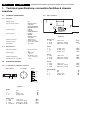
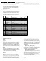
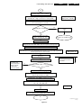
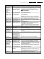
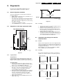
GB 20
5.
EM1A
Fault finding and repair tips
ERROR: 9 6 0 0 0 0 0 : Error code 6 was first detected and
error code 9 is the last detected (newest) error
error code (and not the actual cause). E.g. a fault in the
protection detection circuitry can also lead to a protection.
The contents of the error buffer can also be made visible
through the 'blinking LED' procedure. This is especially
useful when there is no picture. See paragraph 5.6 'The
blinking LED procedure '.
5.5.2
Error codes
In case of non-intermittent faults, clear the error buffer before
starting the repair. This is to prevent that 'old' error codes are
still present.
If possible, check the entire content of the error buffer. In
some situations an error code is only the result of another
Error Device
Description
Def. item
Diagram
0
1
FBX 3V3 prot
FBX 3V3 protection
5703
B3
2
No HFB
No Horizontal Flyback
0325
A4
3
X-Ray protection
X-Ray protection
4
5 V protection
5 V protection
5
No HOP POR
Startup failure
6
General I2C bus error
General I2C bus error
1200/7651 A7/B6
B4
7
Mains Dip error
HW-error
10
MC24C32
NVM communication error
7012
11
MC24C32
NVM identification error
7012
12
SAA5667
Main µP, int. RAM test failure
7001
B7
13
TEDE9
Main Tuner
1200
A7
14
MSP3415D
MSP34xx
7651
B6
15
CY7C1019
SRAM test failure
7011
B7
C2
B7
16
TELE9
PIP/DW Tuner
7201
17
SAB9081H
Multi PIP-IC
7801
C1
18
M62320P
PIP/DW IO-expander
7403
C3
23
TDA888xx
PIP/DW BOCMA-IC
7301
C4
27
Virtual Dolby
Virtual Dolby error
30
TDA9320
HIP I/O-video processing
7323
B2
31
SAA4978
PICNIC
7709
B3
32
TDA9330
HOP video control/geometry
7301
B4
Explanation of error codes:
Error 0
No errors.
Error 1
This protection is activated, when the PICNIC (pos. 7709 on
diagram B3) can not communicate via I2C for a certain time.
This could mean that stabiliser 7713 is defective. When e.g.
2704 makes a short circuit to ground, 7713 will become very
hot. For safety reasons the set will be switched to protection
mode.
Error 2
The absence of an HFB-pulse (pin 4 of connector 0324 on
LSP, diagram A3) is detected by the HOP (pos. 7301 on
diagram B4). A bit will be set in the HOP. After filtering by the
software, the set will switch to protection mode.
Error 3
Reserved.
Error 4
When the +5 V protection is active, the set is switched to
protection and error code 4 is placed in the error buffer. The
LED will blink 4 times (repeatedly). A 5 V failure can cause
a drop in the 5 V supply output, resulting in an undefined
behaviour of the set. Therefore, some I2C devices (Tuner
and MSP) connected to the 5 V supply are constantly
monitored. When none of these devices responds to the
micro controller for a prolonged time, the micro controller
assumes that there is a failure in the 5 V supply. By starting
up the set via grounding of the FRONT_DETECT-line (on the
side I/O), the +5 V protection will be overruled and it will be
easier to determine the cause. The +5V protection will be
activated when these I2C devices fail (no I2C
communication):
– Main Tuner (pos. 1200 on the LSP),
– MSP34xx sound processor (pos. 7651 on the SSB).
The following tips are useful to isolate the problem area, after
overriding the +5 V protection. Determine whether:
– The MSP sound processor is loading the +5 V; isolate
3650 and/or 4604 (see diagram B6).
– The main Tuner is loading the +5 V source; isolate coil
5200.
Caution! Overriding the +5 V protection when there is a 5 V
failure can increase the temperature in the set and may
cause permanent damage to components. Do not override
the +5V-protection for a prolonged time.
Error 5