1
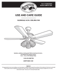
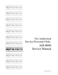
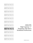
$/3+$
0,&526<67(06
5,*+7 )520 7+( 67$57
$/3+$
0,&526<67(06
5,*+7 )520 7+( 67$57
$/3+$
0,&526<67(06
5,*+7 )520 7+( 67$57
$/3+$
0,&526<67(06
5,*+7 )520 7+( 67$57
$/3+$
0,&526<67(06
5,*+7 )520 7+( 67$57
$/3+$
0,&526<67(06
5,*+7 )520 7+( 67$57
$/3+$
0,&526<67(06
AM-212-20
SCSI 3-1/2”
Floppy Diskette Drive
Installation Instructions
5,*+7 )520 7+( 67$57
$/3+$
0,&526<67(06
5,*+7 )520 7+( 67$57
$/3+$
0,&526<67(06
5,*+7 )520 7+( 67$57
$/3+$
0,&526<67(06
5,*+7 )520 7+( 67$57
$/3+$
0,&526<67(06
5,*+7 )520 7+( 67$57
$/3+$
0,&526<67(06
5,*+7 )520 7+( 67$57
$/3+$
0,&526<67(06
5,*+7 )520 7+( 67$57
PDI-00212-20, Rev. A01
FIRST EDITION: January 1999
To re-order this document, request part number PDI-00212-20
FCC Notice
This equipment has been tested and found to comply with the limits for a Class A digital device, pursuant to Part 15 of the FCC Rules.
These limits are designed to provide reasonable protection against harmful interference when the equipment is operated in a
commercial environment. This equipment generates, uses and can radiate radio frequency energy and, if not installed and used in
accordance with the instruction manual, may cause harmful interference to radio communications. Operation of this equipment in a
residential area is likely to cause harmful interference in which case the user will be required to correct the interference at his own
expense.
Canadian Department of Communications Compliance Statement
This equipment does not exceed Class A limits per radio noise emissions for digital apparatus set out in the Radio Interference
Regulations of the Canadian Department of Communications. Operation in a residential area may cause unacceptable interference to
radio and TV reception requiring the owner or operator to take whatever steps are necessary to correct the interference.
Avis de Conformité aux Normes du Ministère des Communications du Canada
Cet équipment ne deapsse pas les limits de Classe A d'émission de bruits radioélectriques pour les appareils numeriques tels que
prescrites par le Règlement sur le brouillage radioélectrique établi par le ministère des Communications du Canada. L'exploitation faite
en milleu résidential peut entrainer le brouillage des réceptions radio et tele, ce qui obligerait le propriétaire ou l'opératour à pendre les
dispositions nécessaires pour en éliminer les causes.
Battery Warning
CAUTION: Danger of explosion if battery is incorrectly replaced. Replace only with the same or equivalent type recommended by the
manufacturer. Discard used batteries according to the manufacturer's instructions.
ATTENTION: Il y a danger d'explosion s'il y a replacement incorrect de la batterie. Remplacer uniquement avec une batterie du même
type ou d'un type recommandé par le constructeur. Mettre au rébut les batteries usagées conformément aux instructions du fabricant.
For AM-3500-E100, -E200, -E300, -E400, -E500 and AM-990-01 systems replace battery with Panasonic or Ray-O-Vac BR2325 only.
For AM-3500-E250, AM-3500-E450, E550, AM-3500-6000, AM-3500-7000, and AM-990-04 systems, replace batteries with Panasonic
or Ray-O-Vac BR1225 only. Use of other batteries may present a risk of fire or explosion. Replacement batteries may be ordered from
your authorized Alpha Micro reseller.
Electrical Warning
This equipment contains components that can be damaged by static electricity. Follow all electronic discharge precautions when
handling the equipment. For example, touch the metal back panel of the CPU or peripheral chassis to dissipate any electrical charge
before touching the circuit boards or equipment within the chassis. After turning off power, before you open your computer chassis,
unplug the cord from the electrical outlet to guard against electrical shock.
SOFTWARE SECURITY DEVICE IDENTIFICATION NUMBER: _________________
The Alpha Micro Software Security Device (SSD) is a customized integrated circuit that personalizes the computer, providing identity
verification for it. Certain Alpha Micro and non-Alpha Micro software may require that your computer contain an SSD in order to run
software that has been customized to run only on your computer.
Please enter the identification of your SSD above. The SSD identification number should be on your computer ID label under "SSD
Serial No." (Another way of finding the number is to look at the SSD itself. The SSD is located in an integrated circuit location on the
CPU board; its identification number is printed on the SSD itself.) Software vendors may ask you for the SSD number if they are
customizing software to run only on your computer.
This document may contain references to products covered under the following U.S. Patent Number(s): 4,530,048
ALPHA MICRO PRODUCTS
17534 Von Karman
Irvine, CA 92614
Table of Contents
INTRODUCTION
PRODUCT DESCRIPTION
TOOLS REQUIRED
PREPARING THE AM-212-20 FOR INSTALLATION
Setting the SCSI ID
SCSI BUS TERMINATION
External SCSI Bus Termination
TERMINATION POWER
INSTALLING THE AM-212-20
SOFTWARE INFORMATION
Creating a software driver
Modifying the System Initialization Command File
Modifying the Device Table
Adding a BITMAP statement
Adding the Device Driver to System Memory
Testing the initialization file
Formatting and initializing a diskette.
Using your diskette drive.
Booting from the AM-212-20 diskette.
1
1
1
2
2
3
3
3
4
4
4
6
6
6
7
8
8
9
9
List of Figures
Figure 1 - AM-212-20 SCSI Floppy Drive Jumper Configuration
PDI-00212-20, Rev. A01
2
Installation Instructions: AM-212-20 3-1/2" Floppy Diskette Drive
Page 1
INTRODUCTION
This document provides hardware and software instructions for installing and using an AM-212-20 SCSI
diskette drive assembly in an Eagle 450 or AM-6000 series computer system. The AM-212-20 is a
narrow SCSI device that attaches to the existing SCSI bus in the computer system. Enhanced
performance of the diskette is achieved by utilizing existing AMOS features including DCACHE, and
disk write caching when using native AM-SCSI format diskettes.
If you are installing an AM-212-20 floppy drive into an external subsystem, use the installation
instructions shipped with the subsystem together with the information provided in this document.
These instructions are written for the experienced Alpha Micro Service Technician, so if you do not feel
comfortable performing the hardware and software procedures discussed below, please contact your
Alpha Micro dealer or the Alpha Micro Technical Assistance Center for help.
PRODUCT DESCRIPTION
AM-212-20 is the Alpha Micro model name for the SCSI bus compatible 3-1/2” floppy diskette drive.
This product is supported only on the AM-6000, AM-6060 and Eagle 450 AMOS based computer
systems. The floppy drive has a narrow SCSI (50-pin) interface that connects directly to the narrow SCSI
bus. For connection to wide SCSI (68-pin) environments, utilize a special right angle narrow-to-wide
SCSI adapter (PDB-00440-92), available from Alpha Micro. No separate controller is required.
The AM-212-20 introduces a new native SCSI diskette format (AM-SCSI) that is not compatible with
previous Alpha Micro diskette systems. For compatibility, the AM-212-20 also supports the traditional
AMOS format and MS-DOS format diskettes. The AM-212-20 is a 3.5" diskette drive using standard,
readily available, 3.5" diskettes. The following formats are supported:
AMOS 720KB 3.5" double density
AMOS 1.44MB 3.5" high density
PC 720KB 3.5" double density
PC 1.44MB 3.5" high density
AM-SCSI 720KB 3.5" double density
AM-SCSI 1.44MB 3.5" high density
The AM-212-20 floppy diskette product installation package consists of the diskette drive itself and the
necessary hardware to mount it into the computer chassis.
The AM-212-20 has the same environmental specifications as your computer. Operational specifications
are contained in the documentation that accompanied your computer system.
TOOLS REQUIRED
For most installations, the only tool you will need to install the AM-212-20 is a #2 Phillips-head
screwdriver.
PDI-00212-20-00, Rev. A01
Page 2
Installation Instructions: AM-212-20 3-1/2" Floppy Diskette Drive
PREPARING THE AM-212-20 FOR INSTALLATION
Before installing the AM-212-20, you should make sure its configuration jumpers are set correctly.
These jumpers are found on the rear of the diskette drive, as shown in Figure 1. Specifically, you need to
set the jumpers determining the SCSI ID for the drive, and insure that the SCSI bus terminators are
removed unless the AM-212-20 is the last physical SCSI device connected to the SCSI bus and you are
not using the external SCSI terminator to terminate this SCSI bus.
4
SCSI FLOPPY DRIVE
TOP VIEW
2
DC POWER
CONNECTOR
1
SCSI ID 5
DETAIL
shorting block out = 1
shorting block in = 0
50 PIN SCSI BUS CONNECTOR, PIN1
SCSI BUS TERMINATORS (2) REMOVED, PIN 1 INDICATED
SCSI ID 5 (SEE DETAIL)
Note: All other jumper blocks are factory
set and should NOT be moved.
Figure 1 - AM-212-20 SCSI Floppy Drive Jumper Configuration
The next few sections discuss SCSI IDs and SCSI bus termination.
Setting the SCSI ID
Each SCSI device attached to the SCSI bus must be set to a unique address. Two SCSI devices cannot
share the same address. The AM-212-20 is a SCSI-1 device, and can be set to any SCSI ID from 0
through 6. Figure 1 shows the standard jumper settings for SCSI ID = 5, which is the standard SCSI
address for the AM-212-20.
If you are using this device with a wide SCSI bus adapter attached to a wide SCSI bus, only SCSI
IDs 0-6 are supported for this device.
PDI-00212-20, Rev. A01
Installation Instructions: AM-212-20 3-1/2" Floppy Diskette Drive
Page 3
SCSI BUS TERMINATION
To function properly, the SCSI bus on your computer must be terminated at each end. The SCSI
controller on the system CPU board terminates one end of the bus; the opposite end of the bus can be
terminated in one of two ways: 1) using the preferred method—an external terminator, or 2) installing onboard terminators in the peripheral that's at the other end of the SCSI cable. You should use method 2
only if, for some reason, you cannot use an external terminator.
External SCSI Bus Termination
The preferred way to terminate the SCSI bus in an AMOS computer is to install an external terminator.
Using an external terminator makes it easier to install an add-on subsystem (like a portable CD-ROM
drive), eliminating the need to remove terminators from a SCSI device inside the computer.
Several different external terminators are available from Alpha Micro:
Part Number
PRA-00222-00
PRA-00222-21
PRA-00222-20
Terminator Type
Narrow, passive
Narrow, active
Wide, active
The type of terminator you need depends on your computer and the SCSI peripherals in it. The AM-21220 is supported only on the AM-6000, AM-6060 and Eagle 450 computer systems, and therefore requires
an active terminator, either narrow or wide, depending upon the type of SCSI bus contained in your
computer system. This terminator is provided as a standard part of your computer system.
To use the external terminator, you need to insure that none of the SCSI devices inside the computer are
terminated. You also need to follow the guidelines in the section on providing termination power to the
SCSI bus, below.
TERMINATION POWER
To control SCSI bus termination properly, a termination power source must be provided; this is
especially important when using an external terminator.
Why is Termination Power so important when using an external terminator?
Any terminator must have a power source. Because an external terminator does not have its own source
of power, it must get its termination power from the SCSI bus. If termination power is not available on
the bus, the external terminator cannot do its job, which means your SCSI bus will not be terminated
properly. This may result in a computer that won't boot, or that "hangs" frequently.
All AMOS computers using the SCSI-2 or Wide SCSI-2 bus should be configured to supply termination
power via the host controller. When SCSI bus termination power is supplied by the host controller, no
SCSI peripheral should supply termination power to the bus.
SCSI subsystems attached to the main system should not have any additional devices supplying
termination power to the SCSI bus. Termination power should be supplied by the SCSI controller only!
PDI-00212-20-00, Rev. A01
Page 4
Installation Instructions: AM-212-20 3-1/2" Floppy Diskette Drive
INSTALLING THE AM-212-20
The following sections explain how to install the SCSI floppy drive and cable it to your computer.
Follow the instructions in your computer Owner's Manual for turning off the power to the system. Be
sure to observe the cautions concerning electrostatic discharges and grounding.
The AM-212-20 must be installed in one of the three 5-1/4” mounting bays at the top and front of your
computer system chassis. Before proceeding with the installation, make sure all jumper settings are
installed per the previous section, and orient the floppy diskette drive so that the SCSI connector and
jumper blocks are facing upwards.
Complete instructions for installing SCSI peripherals are included in the service manual for the Eagle
series, AM-6000, and other computers that use the Eagle deskside or AM-990 chassis. Use these
instructions to install your AM-212-20 floppy diskette drive and then use the instructions in this
document to complete the software portion of the installation.
Once the physical installation is complete, make sure to plug in both the power and SCSI bus cable to the
floppy drive. See the following caution for SCSI cabling abnormality.
Note that the SCSI connector orientation is such that a twist in the SCSI cable is required to mate
pin 1 of the cable with pin 1 of the floppy drive SCSI connector.
SOFTWARE INFORMATION
Three software files are required for complete operation of the AM-212-20 SCSI diskette drive in
addition to the standard AMOS release software contained on the 10/98 AlphaCD. These files or updated
versions, will be included in future standard AMOS releases. These files may be obtained from Alpha
Microsystems’ TABBS on-line support system, or the 04/99 or later AlphaCD.
OPR:AM212.DIR
DVR:FLP138.DVR
DVR:FLPR60.DVR
SYS:FMSFLP.LIT
The directory listing for the above software
The AM212-20 device driver for Eagle 450
The AM212-20 device driver for AM-6000 series
The AM212-20 diskette formatting utility
You should now use FIXLOG to create a permanent fully featured driver for your AM212-20 diskette
drive using the FLP138.DVR or FLPR60.DVR provided and following the instructions in the
following sections.
Creating a software driver
The program used to make the software drivers for use with the AM-212-20 is called FIXLOG.LIT.
FIXLOG allows you configure generic software drivers to create systems drivers to support the 6
possible floppy formats:
PDI-00212-20, Rev. A01
Installation Instructions: AM-212-20 3-1/2" Floppy Diskette Drive
Diskette Format
Page 5
Suggested Drive Name
AMOS 720KB
AMOS 1.44MB
PC 720KB
PC 1.44MB
AM-SCSI 720KB
AM-SCSI 1.44MB
AMD:
AMH:
PCD:
PCH:
FLD:
FLH:
The name of the generic driver file is system dependent and corresponds to the name used for your
generic SCSI disk driver. For example:
Eagle 450 with AM-138 CPU board
AM-6000 or 6060 with Roadrunner 060 board
FLP138.DVR
FLPR60.DVR
FIXLOG allows you to configure the driver for the SCSI device ID (usually 5), the number of logical
disks (usually 1), and the number of read-ahead blocks (usually 7). Read-ahead is not supported in the
AMOS compatibility mode and the driver will ignore the read-ahead configuration provided by
FIXLOG.
To create a diskette driver do the following:
LOG DVR:
FIXLOG
Fixlog.lit Version x.x(xxx)
1.
2.
Change the number of logicals
Create a sub-system driver
Enter choice: 2
Enter the name of the generic driver to be used: FLP138
(use FLPR60 for AM-6000 systems)
Enter number of logical drives per physical unit: 1
Enter the SCSI ID(0-15): 5
Enter number of read-ahead blocks: 7
Enter new driver name: FLH
New driver is now in memory.
To save the software driver to your hard disk drive, type
SAVE FLH
The answers to the above questions, naturally, depend on the type of driver you are creating and the SCSI
ID of your diskette drive.
You must have drivers for each diskette format you expect to use on your system.
PDI-00212-20-00, Rev. A01
Page 6
Installation Instructions: AM-212-20 3-1/2" Floppy Diskette Drive
Modifying the System Initialization Command File
In order to use your diskette drive, you must define it in the system initialization file. First use the COPY
command to make a copy of your current system initialization command file, calling it TEST.INI. For
example:
LOG SYS:
COPY TEST.INI=AMOS32.INI
Then edit TEST.INI using the AlphaVUE text editor, making the modifications discussed in the
following sections.
WARNING! NEVER modify the system initialization command file directly. Always make a
copy and modify the copy. If you modify your AMOSL.INI or AMOS32.INI file directly and
make a mistake, your computer may not boot! If you make a copy, you can test your changes
using the MONTST command, as described below, then rename the test command file to
AMOSL.INI or AMOS32.INI only when you know it works correctly.
The following sections describe the steps required to define a diskette drive in your system initialization
command file.
Modifying the Device Table
The first thing you need to do in your TEST.INI file is add a new DEVTBL statement. In the system
initialization file, DEVTBL tells AMOS which devices to look for on the computer. The DEVTBL lines
in bold below define 3.5" diskette drive formats.
DEVTBL DSK
DEVTBL FLH0
DEVTBL FLD0
;AM-SCSI format high density diskette
;AM-SCSI format double density diskette
Adding a BITMAP statement
The next step is to add a BITMAP statement for the diskette drive.
BITMAP DSK
BITMAP FLH,179,0
BITMAP FLD /P:89
;bitmap for high density AM-SCSI
;paged bitmap for double density AM-SCSI
This is only an example. Make sure the BITMAP statements you add use the correct device names
and bitmap sizes for your diskette formats.
The following gives the correct bitmap sizes for the supported diskette formats:
PDI-00212-20, Rev. A01
Installation Instructions: AM-212-20 3-1/2" Floppy Diskette Drive
Diskette Format
AMOS 720KB
AMOS 1.44MB
PC 720KB
PC 1.44MB
AM-SCSI 720KB
AM-SCSI 1.44MB
Page 7
Bitmap Size
90
180
90
180
89
179
Adding the Device Driver to System Memory
You must load the driver into system memory. For the AM-212-20 diskette drivers you must also specify
the diskette format and density on the SYSTEM command line. Failure to specify this information will
cause the driver to use the default values for a high density (1.44MB) native AM-SCSI format diskette.
The SYSTEM command line has the following format for the AM-212-20 diskette drivers:
SYSTEM driver/N /F:format /D:density cache-size flush-time
format can be:
AMOS
DOS
SCSI
traditional AMOS compatibility format
MS-DOS format
AM-SCSI format
density can be:
720
1.44
720 KB double density
1.44 MB high density format
cache-size
is the size of the write cache buffer for those formats that
support write caching and is ignored for those formats that don't.
flush-time
is the maximum number of seconds to wait before forcing
cached data to be written to the diskette. One (1) second is
recommended for the AM-212-20 diskette.
Only the first character of the switch value shown above is required. However, using the full switch name
makes the command line more understandable. Spaces are not allowed within the switch strings.
Add SYSTEM statements similar to these before the final system command:
SYSTEM FLH.DVR[1,6]/N /F:SCSI /D:1.44 200K 1
;
;load AM-SCSI high density driver and initialize write
;cache with a 200KB buffer and a 1 second maximum
;time between buffer flushes
SYSTEM FLD.DVR[1,6]/N /F:SCSI /D:720
;
;load AM-SCSI double density driver without write cache
PDI-00212-20-00, Rev. A01
Page 8
Installation Instructions: AM-212-20 3-1/2" Floppy Diskette Drive
SYSTEM AMH.DVR[1,6]/N /F:AMOS /D:1.44
;
;Load AMOS compatible high density driver
The AM-212-20 diskette drivers require the SCSI dispatcher for your system. Your system initialization
file probably already loads and initializes the appropriate dispatcher, and therefore should not require
changing when adding the AM-212-20 to your system. There should be a line similar to:
SCZDSP SCZ138 /arguments
;SCSI dispatcher for AM-450
;arguments will depend on
;your particular system
;configuration
Testing the initialization file
When you have finished editing the TEST.INI file enter F RETURN to finish and exit from AlphaVUE.
Warn other users on your system that you will be rebooting the system, then use the MONTST program
to reboot. For example:
MONTST AMOS32,TEST
Watch the terminal screen to make sure your computer boots without error. If the system boots
successfully, copy your test initialization file to your "real" initialization file name. For example:
LOG SYS:
COPY AMOS32.INI=TEST.INI
Note: You can change your CMOS boot settings instead if desired.
You must create and install different drivers for each format diskette you will use on your system. For
example, if you use AM- SCSI format and PC format 1.44MB diskettes, you will need two drivers
(FLH: and PCH:). Usually, these will be copies of the one made with FIXLOG. Only the AM-SCSI
format uses read-ahead.
Formatting and initializing a diskette
Follow the steps below to format and initialize a native SCSI format diskette.
These steps erase all data on the diskette! Before you use the format program, make sure the
diskette is blank, or does not contain files you need!
Insert the diskette into the drive; don't use the MOUNT command. Instead enter:
LOG OPR:
FMSFLP
See the FMSFLP command reference sheet at the end of these installation instructions.
PDI-00212-20, Rev. A01
Installation Instructions: AM-212-20 3-1/2" Floppy Diskette Drive
Page 9
The FMSFLP program will look for all SCSI removable media disk devices on your system and display
them in a window on your terminal screen. Use the arrows to highlight the diskette drive and press
return. You can use the arrow keys to select the desired command from the list and either FORMAT or
INITIALIZE the diskette. If the diskette is pre-formatted, INITIALIZE will setup an AMOS disk
structure on the diskette without actually re-formatting the entire diskette.
Although traditional AMOS diskettes may be formatted with FMSFLP, system performance with the
formatted diskette will be slow. Therefore, we recommend that traditional AMOS format diskettes be
pre-formatted on a different computer with an AM-219 diskette controller for highest system
performance. PC format diskettes must be pre-formatted on a PC.
Using your diskette drive
IMPORTANT! Each time you are going to remove a diskette from the drive you must unmount
the diskette by typing MOUNT dev0:/U, where dev is the drive name you have chosen.
Failure to properly unmount the diskette could cause corrupted data files.
First insert your diskette in the drive. Then mount the diskette using the appropriate device name. For
example, if you are using a high density traditional AMOS format diskette, type:
MOUNT AMH0:
You may access the diskette using normal AMOS commands and programs.
When you are finished using the diskette, unmount it by typing:
MOUNT AMH0:/U
This command will wait for all diskette drive activity to complete before returning to the AMOS prompt.
(This could be many seconds if you are using a large write cache)
You cannot use normal AMOS commands to read or write PC format diskettes. Instead, you must use
the special DOS floppy diskette commands: DOSDR, DOSTYP, DOSIMP, DOSEXP,
DOSMKD, DOSDEL, DOSRMD. See the AMOS COMMAND REFERENCE MANUAL for
descriptions of these commands.
Booting from the AM-212-20 diskette
Booting from the AM-212-20 diskette drive is not supported.
PDI-00212-20-00, Rev. A01
FMSFLP
FUNCTION
Formats diskettes using the AM-212-20 SCSI diskette drive, initializes diskettes, or rewrites the hidden
sector.
CHARACTERISTICS
FMSFLP is re-entrant and re-usable.
To run FMSFLP you must be logged into the System Operator’s Account.
To run FMSFLP, your computer must support the AM-212-20 floppy disk drive. You must have a SCSI
dispatcher installed, and have an AM-212-20 diskette drive attached to the SCSI bus contained in your
computer.
FMSFLP supports narrow and wide SCSI interfaces.The AM-SCSI and traditional AMOS format is
supported, but PC formats are not supported and must be pre-formatted on a PC.
FORMAT
FMSFLP
RETURN
If you use the format or initialize option, FMSFLP destroys all data on all logical
devices on the diskette!
OPERATION
FMSFLP runs in interactive mode.
FMSFLP displays a list of the removable media SCSI drives on your computer. Select the drive you want
to use and press RETURN . The FMSFLP menu then displays, as shown:
System Commands Reference Manual, Rev. 09
FMSFLP
Page 2
Alpha Micro SCSI Floppy Media Format Utility
FMSFLP Version 1.0(100)
Selected SCSI
Functions
Select Drive
Drive Info
ID: 05
Vendor: TEAC
Reassign Blocks
List Defects
Model: FC-1
HF
Rewrite Hidden Sector
Initialize Drive
11 Rev. RV J
Format
Mode Sense
Logical Format Parameters
Media Format.......AM-SCSI HD
Directory Type....Traditional
Usable Capacity
Optimize for Capacity.....Yes
Logical Drive Size 1.40 MB
Number of Logicals..........1
Bitmap Size...............179
Drive Utilization
1.40 MB
100.00%
Select logical drive parameters and press Return to continue
or press ESCape to abort
AMOS format is for compatibility with older floppy disk systems
To navigate the menus use , , , and . To invoke a highlighted function press RETURN . To abort
menu functions and return to the AMOS prompt press ESC or CTRL /C. To return to menu functions from
submenus press ESC .
You can do any of the following:
SELECT DRIVE
Selects drive to use in the operations listed below.
REASSIGN BLOCKS
The AM-212-20 does not support this function.
REWRITE HIDDEN SECTOR
Re-initializes the media’s hidden sector. If the hidden sector becomes corrupted, you may use this
command to restore it without destroying any user data (assuming the hidden sector is initialized as it
was before it became corrupted).
Whenever the hidden sector is written, the diagnostic cylinder is also re-initialized. This
is necessary since the diagnostic cylinder always begins right after the last logical drive
defined on the media.
This is ignored for AMOS compatible diskettes, which do not have a hidden sector.
FORMAT
Formats and initializes the media in the selected drive. You can select the media format, directory type,
and either set the bitmap size and number of logicals or have FMSFLP optimize the logical
configuration. Here are the settings for some common configurations:
System Commands Reference Manual, Rev. 09
Page 3
FMSFLP
• For traditional directories using the entire drive with the largest possible bitmaps:
set Directory Type to Traditional and Optimize to Yes. FMSFLP calculates both bitmap
size and number of logical devices.
• For extended directories using the entire drive: set Directory Type to Extended and
Optimize to Yes. Enter the number of logical devices you want. FMSFLP calculates the
best bitmap size.
• For any other removable media configuration, you can set Optimize to No and enter the
Directory Type, Bitmap Size, and Number of Logicals you want.
The number of logicals must be one (1) for AMOS format media. Although AM-SCSI
format media will support multiple logical devices, one (1) logical is recommended for
these diskettes.
The type of media in the drive is not detected prior to formatting, so the configuration
defaults to high density AM-SCSI.
After choosing a configuration, press
RETURN
to continue.
If you decide you don’t want to format the drive, select Cancel and press
begins formatting when you make your selection.
RETURN .
Otherwise, the drive
DRIVE INFO
Displays the following information about the currently selected media if available.:
• Usable capacity.
• Block size.
• Format status.
• Formatted capacity: amount of space being used for logical drives.
• Number of logicals.
• Size of each logical drive.
• Bitmap size.
• Cylinders, heads, and sectors per track. These are calculated values; they don’t reflect the
physical structure of the drive.
AMOS formatted media does not have the information available to display the logical
information.
LIST DEFECTS
The AM-212-20 floppy diskette drive does not support this feature.
System Commands Reference Manual, Rev. 09
FMSFLP
Page 4
INITIALIZE MEDIA
Same as the format option described above, except that it doesn’t format the media before writing the
logical drive information.
If the diskette’s formatting is OK, use this option instead of format. This will save you
time.
If you initialize a diskette using a density that differs from its formatted density, the
diskette will be unusable.
MODE SENSE
Retrieves mode sense information from the drive. You can view these values:
• Current Values: control the current operation of the drive.
• Changeable Values: indicate which bytes/bits are changeable.
• Saved Values: control the current operation of the drive, unless they are changed by a
Mode Selected command.
• Default Values: used by the drive if current values have not been set or the drive is
unable to access its saved values.
The information you requested is displayed within a scrollable window. Use
information. Press ESC when you are done.
and
to view the
ERROR MESSAGES
?Logical format exceeds usable drive capacity!
You specified a logical drive count and bitmap size that exceeds the capacity of the
drive. Specify a smaller number of logical drives and/or bitmap size.
?Program requires AMOS/32 execution!
FMSFLP requires an MC68020 or later processor. It will not run on a computer with an
MC68000 or MC68010 processor.
?You must install a SCSI dispatcher to use FMSFLP on the system!
You are trying to run FMSFLP on a system that has a SCSI interface but does not have a
dispatcher installed.
?Device error id 5 - sense key: 03 (media error) additional sense: 12h 00h!
Ignore this error message.
System Commands Reference Manual, Rev. 09