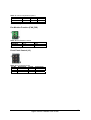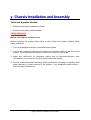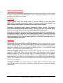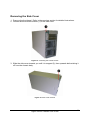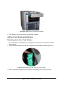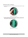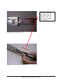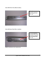
1
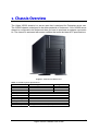
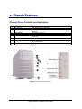
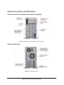
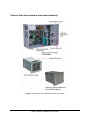
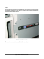
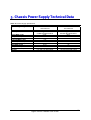
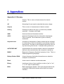
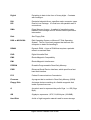
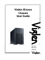
Viglen IX2000 Chassis User Guide ® Great M inds Think C O M P U T E R S . N E T W O R K S . ® S O L U T I O N S Viglen EMC and the 'CE' mark CE Marking As we begin the 21st century, European standards are being harmonised across borders. If products comply with the same standards in all European countries, product exporting and importing is made simple - paving our way to a common market. If you buy a product with a 'CE' mark on it (shown below), on the box, in the manual, or on the guarantee - it complies with the currently enforced directive(s). Introduction to EMC EMC (Electromagnetic Compatibility) is the term used to describe certain issues with RF (Radio Frequency) energy. Electrical items should be designed so they do not interfere with each other through RF emissions. E.g. If you turn on your microwave, your television shouldn't display interference if both items are CE marked to the EMC directive. If emitted RF energy is not kept low, it can interfere with other electrical circuitry - E.g. Cars Automatic Braking Systems have been known to activate by themselves while in a strong RF field. As this has obvious repercussions ALL electrical products likely to cause RF related problems have to be 'CE' marked from 1st January 1996 onwards. If a product conforms to the EMC directive, not only should its RF emissions be very low, but its immunity to RF energy (and other types) should be high. The apparatus has to resist many 'real world' phenomena such as static shocks and mains voltage transients. Viglen’s Environment laboratory To gain a 'CE' mark, the Viglen computer range has had to undergo many difficult tests to ensure it is Electromagnetically Compatible. These are carried out in the in-house 'Environment lab' at Viglen Headquarters. We have made every effort to guarantee that each computer leaving our factory complies fully with the correct standards. To ensure the computer system maintains compliance throughout its functional life, it is essential you follow these guidelines. Install the system according to Viglen’s instructions If you open up your Viglen System: Keep internal cabling in place as supplied. Ensure the lid is tightly secured afterwards Do not remove drive bay shields unless installing a 'CE' marked peripheral in its place The clips or ‘bumps' around the lips of the case increase conductivity - do not remove or damage. Do not remove any ferrite rings from the L.E.D cables. Only use your Viglen computer with 'CE' marked peripherals This system has been tested in accordance with European standards for use in residential and light industrial areasthis specifies a 10 meter testing radius for emissions and immunity. If you do experience any adverse affects that you think might be related to your computer, try moving it at least 10 meters away from the affected item. If you still experience problems, contact Viglen’s Technical Support department who will put you straight through to an EMC engineer - s/he will do everything possible to help. If modifications are made to your Viglen computer system, it might breach EMC regulations. Viglen take no responsibility (with regards to EMC characteristics) of equipment that has been tampered with or modified. Viglen IX2000 Chassis User Guide 1 Copyrights and Trademarks Please note The material in this manual is subject to change without notice. Trademarks Microsoft, Windows, Windows 2003, Windows XP, Windows 2000, Windows NT, Windows 95, MS-DOS and OS/2 are registered trademarks of Microsoft Corporation. i386, i486, Xeon, Pentium, Pentium Pro and MMX are registered trademarks of Intel Corporation. JAC-UP, Contender, Dossier, VIG, Viglen, VigStor and Envy are trademarks of Viglen Limited. Genie and Contender are registered trademarks of Viglen Limited. Copyright and Patents This manual and all accompanying software and documentation are copyrighted and all rights reserved. This product, including software and documentation, may not, in whole or in part, be copied, photocopied, translated or reduced to any electronic or machinereadable form, without prior written consent except for copies retained by the purchaser for backup. © Copyright 2005 Viglen Limited All Rights Reserved Viglen IX2000 Server Chassis Version 1.0 Printed in the United Kingdom Liability No warranty or representation, either expressed or implied, is made with respect to this documentation, its quality, performance, merchantability or fitness for a particular purpose. As a result the documentation is licensed as is, and you, the licensee, are assuming the entire risk as to its quality and performance. The vendor reserves the right to revise this operation manual and all accompanying software and documentation and to make changes in the content without obligation to notify any person or organisation of the revision or change. In no event will the vendor be liable for direct, indirect, special, incidental or consequential damages arising out of the use or inability to use this product or documentation, even if advised of the possibility of such damages. In particular, the vendor shall not have liability for any hardware, software or data stored or used with the product, including the costs of repairing, replacing or recovering such hardware, software or data. Viglen IX2000 Chassis User Guide 2 Contents 1. Chassis Overview 5 2. Chassis Features 6 Chassis Front Controls and Indicators 6 Chassis Front, Rear and Side Views 7 Chassis Backplane Options 9 Serial Attached SCSI Backplane Overview 10 Serial ATA Backplane Overview 13 Ultra320 SCSI Backplane Overview 15 3. Chassis Installation and Assembly 19 Opening the Front Bezel 21 Removing the Side Cover 22 Installing Hard Disk Drives and Cages 23 Hotswap Drive Carrier 23 Installing a Hard Drive Carrier to the Hotswap Cage 24 Installing Hard Drives to the Non Hotswap Cage 25 Removing the Hotswap or Non Hotswap Cage 25 Installing the 120mm Fan Installing a 120mm Fan to the VIG840 Chassis 26 27 Installing the Floppy Drive 28 Installing a 5¼” Device 30 Viglen IX2000 Chassis User Guide 3 Add-on Card Guide and Retainer 31 Detaching the Add-on Card Retainer 31 Releasing the Add-on Card Retainer 32 4. Rail Kit Assembly Guide 33 Rail Kit Features 33 Rail Kit Installation 37 5. Chassis Power Supply Technical Data 45 6. Appendices 46 Appendix A: Glossary 46 Appendix B: Notes 52 Appendix C: Suggestions 56 Viglen IX2000 Chassis User Guide 4 1. Chassis Overview The Viglen IX2000 chassis is a server case that is designed for Enterprise server use. The IX2000 chassis is designed to be either pedestal or rackmount. If the IX2000 server chassis is configured to be rackmount then you have to purchase an adapter conversion kit. The chassis is equipped with power supplies that meet the latest ATX specifications. Figure 1: Pedestal and Rackmount Table 1: IX2000 Physical Specifications Specification Pedestal Type Rack Type Height 620mm 220 mm Width 220 mm 425 mm Depth 425 mm 620 mm Weight 27Kg (approx.) 3.5” Bays One 5.25” Bays Three Hard Disk Bays Eight Backplane Support Serial attached SCSI / Ultra 320 SCSI / Serial ATA Cooling Fans 3 x 120mm Front Facing USB 2 Rackmount Option Yes (Optional Rack Kit Required) Viglen IX2000 Chassis User Guide 5 2. Chassis Features Chassis Front Controls and indicators Table 2: Chassis Front Controls and Indicators Item Feature Description 1 1 x 3.5” Bay Houses the Floppy Disk Drive 2 3 x 5.25” bays Houses the CDROM and additional 5.25” devices e.g. Tape Devices. 3 Power Button Powers the server on. 4 Reset Button Hard reset of the server. 5 Failure Alarm Mute Mutes the redundant PCU alarm. (Disabled in single PSU systems) 6 USB Cover Covers the two USB ports. 7 Key lock Locks access to the hot swap hard disk drives, stops the removal of the front panel 8 Foot stand Holds up the Server chassis in pedestal form Figure 2: Enclosure Front Overview Viglen IX2000 Chassis User Guide 6 Chassis Front, Rear and Side Views Chassis Front View (without front panel installed) Figure 3: Chassis Front View without the Front Panel Chassis Rear View Figure 4: Chassis Rear View Viglen IX2000 Chassis User Guide 7 Chassis Side View (without side panel installed) Figure 5: Chassis Side View (Without Side Panel Installed) Viglen IX2000 Chassis User Guide 8 Chassis Backplane Options The VIG840 chassis allows you to fully customise the backplane options to suit your needs. The chassis offers non hotswap cages, hotswap SAS cages, S-ATA cages and SCSI cages. You are also able to mix and match these options, see table below: Table 3: Chassis Backplane Options Option Cage Option 1 Non hotswap cage 2 Non hotswap cage 3 Non hotswap cage 4 Non hotswap cage 5 Hotswap S-ATA cage 6 Hotswap S-ATA cage 7 Hotswap S-ATA cage 8 Hotswap SCSI cage 9 Hotswap SAS cage 10 Hotswap SAS cage Cage Option Non hotswap cage Hotswap S-ATA cage Hotswap SCSI cage Hotswap SAS cage Hotswap S-ATA cage Hotswap SCSI cage Hotswap SAS cage Hotswap SCSI cage Hotswap SCSI cage Hotswap SAS cage Viglen IX2000 Chassis User Guide 9 SAS/SATA-2 Backplane Overview Back View: Figure 6: SAS/SATA-2 Connector(s) Layout Table 4: SAS/SATA-2 Connector(s) Layout No Description 1 CN2, 4-pin DC Power Connector 2 CN1, 4-pin DC Power Connector 3 SW1, Front Panel Control Jumper 4 JF2, 3P3C Fan Connector Viglen IX2000 Chassis User Guide 10 5 6 7 8 9 10 11 12 CN33, 7P Serial ATA Connector CN43, 7P Serial ATA Connector JF1, 3P3C Fan Connector CN13, 7P Serial ATA Connector CN23, 7P Serial ATA Connector CN5, Hardware Monitor Switch CN3, External HDD Activity LED connector CN4, HDD Fail LED connector Front View: Figure 7: SAS Hard Drive Connector Layout Table 5: SAS/SATA-2 Hard Drive Connector Layout No Description 1 CN41, SAS HDD4 connector 2 CN31, SAS HDD3 connector 3 CN21, SAS HDD2 connector 4 CN11, SAS HDD1 connector Viglen IX2000 Chassis User Guide 11 Jumper Settings on the SAS/SATA-2 Backplane: SW1, Hardware Monitor Switch Table 6: S1 Hardware Monitor Switch Configuration No Function ON OFF 1 FAN1 Monitor Enabled *Disabled 2 FAN2 Monitor Enabled *Disabled 3 Alarm Temperature *65°C 55°C * Default Settings CN5, Front Panel Control Jumper Table 7: CN5 Front Panel Control Jumper Pin No. Function Pin No. 1 System Failure LED+ 2 3 System Failure LED4 5 Key Pin 6 Function N.A. Alarm Mute Switch+ Alarm Mute Switch - CN4, Failed HDD LED Table 8: CN4 Failed HDD LED Pin No. Function 1 Fail LED for HDD CN11 2 Fail LED for HDD CN21 3 Fail LED for HDD CN31 4 Fail LED for HDD CN41 Viglen IX2000 Chassis User Guide 12 Serial ATA Backplane Overview Back View: Figure 6: S-ATA Connector(s) Layout Table 9: S-ATA Connector(s) Layout No Description 1 J9, 4-pin DC Power Connector 2 J10, 4-pin DC Power Connector 3 FAN1, 3P3C Fan Connector 4 FAN2, 3P3C Fan Connector 5 J5, 7P Serial ATA Connector 6 J7, 7P Serial ATA Connector 7 J6, 7P Serial ATA Connector 8 J8, 7P Serial ATA Connector 9 S1, Hardware Monitor Switch 10 JP1, Front Panel Control Jumper Viglen IX2000 Chassis User Guide 13 Front View: Figure 7: S-ATA Hard Drive Connector Layout Table 10: S-ATA Hard Drive Connector Layout No Description 1 J1, serial ATA HDD1 connector 2 J2, serial ATA HDD2 connector 3 J3, serial ATA HDD3 connector 4 J4, serial ATA HDD4 connector Jumper Settings on the SATA Backplane: S1, Hardware Monitor Switch Table 11: S1 Hardware Monitor Switch Configuration No Function ON OFF 1 FAN1 Monitor *Disabled Enabled Viglen IX2000 Chassis User Guide 14 2 FAN2 Monitor 3 Alarm Temperature * Default Settings *Disabled 50°C Enabled *60°C JP1, Front Panel Control Jumper Table 12: JP1 Front Panel Control Jumper Pin No. Function Pin No. 1 System Failure LED+ 2 3 GND 4 5 N/A 6 * Default Settings Function System Failure LEDAlarm Mute Switch+ Alarm Mute Switch - Ultra320 SCSI Backplane Overview Back View: Viglen IX2000 Chassis User Guide 15 Figure 8: Ultra320 SCSI Connector(s) Layout Table 13: Ultra320 SCSI Connector(s) Layout No Description No Description 1 JPWR1,4-pin DC Power 8 TEMP_SET, Alarm Temperature 2 JPWR2,4-pin DC Power 9 J3, Front Panel Control 3 FAN1, 3P3C Connector 10 Terminator connector 4 FAN2, 3P3C Connector 11 SW1, HDD1 ID Switch 5 68-pin SCSI Connector 12 SW2, HDD2 ID Switch 6 FAN_DIS, FAN Monitor 13 SW3, HDD3 ID Switch 7 J2, HDD Motor Control 14 SW4, HDD4 ID Switch Front View: Figure 9: Ultra320 SCSI Hard Drive Connector Layout Table 14: Ultra320 SCSI Hard Drive Connector Layout No Description No Description 1 80-pin SCA Connector 1 3 80-pin SCA Connector 3 2 80-pin SCA Connector 2 4 80-pin SCA Connector 4 Viglen IX2000 Chassis User Guide 16 Jumper Settings on the Ultra320 SCSI Backplane: SCSI ID Switch (SW1, SW2, SW3, SW4) Table 15: SCSI ID Switch Options SCSI ID P1 P2 P3 OFF OFF OFF 0 ON OFF OFF 1 OFF ON OFF 2 ON ON OFF 3 OFF OFF ON 4 ON OFF ON 5 OFF ON ON 6 ON ON ON 7 P4 OFF OFF OFF OFF OFF OFF OFF OFF SCSI ID 8 9 10 11 12 13 14 15 P1 OFF ON OFF ON OFF ON OFF ON P2 OFF OFF ON ON OFF OFF ON ON P3 OFF OFF OFF OFF ON ON ON ON P4 ON ON ON ON ON ON ON ON Hard Disk Drive Motor Control (J2) Table 16: Hard Disk Drive Motor Control Options Operation Mode P1 – P2 P3 – P4 P5 – P6 Open Open Short Normal Short Open Open *Delay Start Open Short Open Remote Start * Default Settings Normal: Motor spins up at DC power on. Delay Start: Motor spins up at DC power on after a delay in seconds 12 times the value of the numeric SEL_ID for the SCSI devices. Remote Start: Motor spins up only when Start Unit commands is received. Alarm Temperature (TEMP_SET) Viglen IX2000 Chassis User Guide 17 Table 17: Alarm Temperature Options Temperature P1 – P2 P3 – P4 Short Open 45°C Open Short *55°C Open Open 65°C * Default Settings P5 – P6 Open Open Short Fan Monitor Function (FAN_DIS) Table 18: Fan Monitor Function Monitor Mode FAN1 P1 – P2 Short *Disabled Open Enabled * Default Settings FAN2 P3 – P4 Short Open Front Panel Control (J3) Table 19: Front Panel Control Pin No Description Pin No Alarm LED+ 1 2 N/A 3 4 Mute Switch 5 6 Description Alarm LEDN/A Mute Switch Viglen IX2000 Chassis User Guide 18 3. Chassis Installation and Assembly Tools and Supplies Needed • Phillips (cross-head) screwdriver (#2 bit) • Antistatic wrist strap (recommended) Safety Warning! Before You Remove the Side Cover Before removing the system side covers to work inside the system, observe these safety guidelines. 1. Turn off all peripheral devices connected to the system. 2. Turn off the system by using the push-button on/off power switch on the front of the system. Then unplug the AC power cord from the system or wall outlet. 3. Label and disconnect all peripheral cables and all telecommunication lines connected to I/O connectors or ports on the back of the system. 4. Provide some electrostatic discharge (ESD) protection by wearing an antistatic wrist strap attached to chassis ground of the system -- any unpainted metal surface -when handling components. Viglen IX2000 Chassis User Guide 19 Warning and Cautions! These warnings and cautions apply whenever you remove the side cover of the system to access components inside the system. Only a technically qualified person should integrate and configure the system. Warning! System power on/off: The on/off button (a convex button) on the front panel DOES NOT turn off the system AC power. To remove power from system, you must unplug the AC power cord from the wall outlet or the system. Hazardous conditions, power supply: Hazardous voltage, current, and energy levels are present inside the power supply. There are no user serviceable parts inside it; servicing should be done by technically qualified personnel. Hazardous conditions, devices and cables: Hazardous electrical conditions may be present on power, telephone, and communication cables. Turn off the system and disconnect the power cords, telecommunications systems, networks, and modems attached to the system before opening it. Otherwise, personal injury or equipment damage can result. Cautions! Electrostatic discharge (ESD) and ESD protection: ESD can damage disk drives, boards, and other parts. We recommend that you perform all procedures in this chapter only at an ESD workstation. If one is not available, provide some ESD protection by wearing an antistatic wrist strap attached to chassis ground --- any unpainted metal surface --- on your system when handling parts. ESD and handling boards: Always handle boards carefully. They can be extremely sensitive to ESD. Hold boards only by their edges. After removing a board from its protective wrapper or from the system, place it component-side up on a grounded, static-free surface. If you place the server board on a conductive surface, the battery leads may short out. If they do, this will result in a loss of CMOS data and will drain the battery. Use a conductive foam pad if available but not the board wrapper. Do not slide board over any surface. Cooling and airflow: For proper cooling and airflow, always install the chassis side cover before turning on the system. Operating it without the cover in place can damage system parts. Viglen IX2000 Chassis User Guide 20 Opening the Front Bezel Take off the front bezel from chassis body. A key lock secures the front bezel to protect your system against unauthorised access: 1. Insert the key into the security lock, and turn it clockwise until it points to the unlock icon as figure 10. 2. Press two release button on top of front bezel and the pull it toward you (Figure 11). 3. Take off the front bezel from chassis body. Figure 10: Security Lock Figure 11: Pressing the Front Panel Release Buttons Viglen IX2000 Chassis User Guide 21 Removing the Side Cover 1. Remove the front bezel. Refer to the previous section for detailed instructions. 2. Loosen the three thumb screws (1) of the side cover. Figure 12: Loosening the Thumb Screws 3. Slide the side cover towards you until it is stopped (2), then upwards before taking it off from the chassis body. Figure 13: Side cover removal Viglen IX2000 Chassis User Guide 22 Installing Hard Disk Drives and Cages The VIG840 supports the following hard disk drive cages: Figure 14: Hotswap & Non Hotswap Hard Disk Drive Cages Hotswap Drive Carrier The hard drive carrier is used in the Hotswap cage shown in Figure 14. Figure 15: Hotswap Drive Carrier Table 15: Hard Drive Carrier Features No Description 1 Contact Spring to chassis 2 HDD Power ON LED 3 HDD activity LED 4 Release button 5 Contact spring to upper 6 Lever 7 Air dam – must be installed if a hard drive is not present. Viglen IX2000 Chassis User Guide 23 Installing a Hard Drive Carrier to the Hotswap Cage 1. Remove the air duct first. 2. Install a hard drive into the carrier, and then secure it with the four screws you can find in the screw bags supplier with each carrier. 3. Insert the hard disk carrier into the Hotswap cage with lever still extended (See Figure 16). Figure 16: Inserting a Hard Drive Carrier 4. Push the lever back until it clicks into place (See Figure 17). Figure 17: Pushing the lever back Viglen IX2000 Chassis User Guide 24 Installing Hard Drives to the Non Hotswap Cage 1. Find the special mounting screws supplied with the server (See Figure 18). Figure 18: Special Mounting Screws 2. Put the hard drives into the cage and align with the mounting holes (See Figure 19). 3. Secure the hard drives to the drive cage using the screws shown in Figure 18. Figure 19: Mounting Holes on the Drive Cage Removing the Hotswap or Non Hotswap Cage 1. Loosen the four thumbscrews, which secure the hard disk drive cage to the chassis body. 2. Pull out the hard disk drive cage slightly (See Figure 20). Figure 20: Pulling out the Cage slightly Viglen IX2000 Chassis User Guide 25 3. Disconnect the SCSI, Serial ATA, or power cables. If necessary the SCSI terminator also needs to be removed. 4. Finally continue to pull out the cage until it is totally out of the drive bay. Figure 21: Completely Removing the Cage from the Chassis Installing the 120mm Fan The VIG840 is designed to support three 120mm cooling fans with screw-less fan holders. There are two fans located in the middle of the chassis and one fan is mounted on the rear panel. To secure a fan in the holder follow the below instructions: 1. Position a 120mm fan into the hooks of the fan holder (See Figure 22). Figure 22: Positioning the hooks Viglen IX2000 Chassis User Guide 26 2. Next press the 120mm fan towards the fan holder until it clicks into place. You will find that the four positioning pins will insert into the four mounting holes of the 120mm fan around the frame. 3. Finally check that all four hooks of the fan holder have exactly fastened to the fan (See Figure 23). Figure 23: Checking the Fan Holder Hooks Installing a 120mm Fan to the VIG840 Chassis 1. Install the 120mm fan to the fan holder (See Figure 24). Figure 24: 120mm Fan Holder 2. Put the four hooks (1) into specified 120mm fan mounting holes (2) at rear panel or middle panels (See Figure 25). Viglen IX2000 Chassis User Guide 27 Figure 25: Mounting the Fan to Chassis Installing the Floppy Drive The VIG840 has a 3½” bay to hold a floppy disk drive. To install a floppy drive follow the below instructions: 1. Loosen the two screws (1) located on the side panel of the floppy disk drive carrier. Figure 26: Loosening the Two Screws 2. Insert the hooks shown by arrows in Figure 27 into the mounting holes of the floppy drive. Viglen IX2000 Chassis User Guide 28 Figure 27: Mounting Hooks 3. Push the floppy disk drive down into the carrier and then secure the drive in place with the two screws that were removed earlier. Figure 28: Securing the Floppy Drive to the Carrier 4. Insert the drive carrier with the floppy drive installed into the 3½” bay until you hear a click sound. Figure 29: Installing the Drive Carrier to the Chassis 5. The floppy drive has now been successfully installed. Viglen IX2000 Chassis User Guide 29 Installing a 5¼” Device The VIG840 can hold up to three 5¼” devices. The below instructions uses a CD-ROM drive to illustrate how to install a 5¼” device to the VIG840 chassis. 1. Remove a pair of slide rails from the side panel of the drive cage frame. Figure 30: Slide Rails 2. Insert both guide pins (Circled in Figure 30) on the slide rail into the mounting holes of the CD-ROM drive and then secure them in place with screws side by side. Figure 31: Securing the Slide Rails to the 5¼” Device 3. Finally, insert the CD-ROM into the 5¼” bay until you hear a click sound. Viglen IX2000 Chassis User Guide 30 Figure 32: Installing the 5¼” Device to the Chassis 4. The floppy drive has now been successfully installed. Add-on Card Guide and Retainer Detaching the Add-on Card Retainer 1. For convenience of installation or cabling the user may want to remove the add-on card retainer. 2. Push the release button on the top of the add-on card holder and then pull it out. Figure 33: Release Button on top of the Add-on Card Holder 3. Move it upwards slightly and then detach it completely from the chassis body. Viglen IX2000 Chassis User Guide 31 Releasing the Add-on Card Retainer 1. Press both release tabs, shown in Figure 34 using red arrows and rotate the retainer towards you. Figure 34: Releasing the Retainer 2. Finally the clamp will be held in the position shown in Figure 35. The user can now install full length PCI cards, which will be guided and secured by the holder. Once all cards have been installed close the retainer. Figure 35: Retainer in Open Position Viglen IX2000 Chassis User Guide 32 4. Rail Kit Assembly Guide Rail Kit Features This latch allows for the slide rails to move in both directions. Figure 36: Side Rail Latch Figure 37: Latch Movement Viglen IX2000 Chassis User Guide 33 This Latch releases the outer rail so that the server can be pushed back into the rack cabinet (One direction). Figure 38: Outer Rail Release Latch Figure 39: Latch being pulled Towards User Viglen IX2000 Chassis User Guide 34 Outer Rail Outer View (Rear location): This is the rear adjustable extension plate located on the outer rail. Figure 40: Rear Adjustable Extension Plate Outer Rail Inner View (Rear Location): The rear adjustable extension plate can be adjusted by loosening the screws located on the inner side of the outer rail. Figure 41: Adjusting the Rear Adjustable Plate Viglen IX2000 Chassis User Guide 35 Outer Rail Outer View (Front Location): This is the front adjustable extension plate. Use the following screws to adjust the length of the rail to fit rack cabinet. Figure 42: Front Adjustable Extension Plate Outer Rail Inner View (Front Location): On the inner side of the rail you have high quality ball bearings which will be used to join the outer rail to the inner rail which is attached to the server. Figure 43: Ball Bearings located on the Inner Side of the Rail Viglen IX2000 Chassis User Guide 36 Rail Kit Installation Step 1: Attach inner rail to chassis. Attach three screws onto the mounting holes located below: Figure 44: Attaching Inner Rail to Chassis Viglen IX2000 Chassis User Guide 37 Step 2: Preparing the outer rail (Front). Use the screws shown below to extend the outer rail so that it fits your rack cabinet. Figure 45: Preparing the Outer Rail (front) Viglen IX2000 Chassis User Guide 38 Step 3: Preparing the outer rail (Rear). Loosen the screws below to free the rear plate so that the outer rail can be extended to fit the rack cabinet. Figure 46: Preparing the Outer Rail (Rear) Viglen IX2000 Chassis User Guide 39 Step 4: Preparing the rack cabinet. Firstly insert moveable screw nuts into the square holes on the front and rear sides of the rack cabinet. Next screw the rails to the front of the rack cabinet from the inside as shown below. Figure 47: Preparing the Rack Cabinet (Front) Viglen IX2000 Chassis User Guide 40 Step 5: Secondly, attach the rear of the outer rail to the back of the rack cabinet from the outside as shown below. Figure 48: Preparing the Rack Cabinet (Back) Viglen IX2000 Chassis User Guide 41 Step 6: Finally, tighten the two screws on the outer rail of the extension plate so that the rail is secure in the rack cabinet. Figure 49: Tighten Screws to Secure Rail Kit to Rack Cabinet Viglen IX2000 Chassis User Guide 42 Step 7: Upload the chassis to the rack cabinet by lining up the outer rails which are now installed in the rack cabinet to the inner rails installed on the sides of the server. Once the rails are lined up push the chassis into the rack cabinet until lock position is achieved. Figure 50: Installing the Chassis to the Rack Cabinet Viglen IX2000 Chassis User Guide 43 Step 8: Once the rails lock they need to be released by the inner rail latch so that the server can be completely pushed into the rack cabinet. The arrow below illustrates what direction to move the latch to release the lock. Figure 51: Releasing the Inner Rail The Server is now mounted successfully into the rack cabinet. Viglen IX2000 Chassis User Guide 44 5. Chassis Power Supply Technical Data Table 16: Power Supply Specification Input Voltage Range Frequency Range Max. input AC Current +3.3V (MAX Load) +5V (Max Load) +12V V1 (MAX Load) +12V V2 (MAX Load) +12V V3 (Max Load) +12V V4 (Max Load) -12V (MAX Load) -5V (MAX Load) +5Vsb (MAX Load) Caution 600W 90~140Vrms or 180~264Vrms 47Hz~63Hz 10A Max @ 110Vac/60Hz 5A Max @ 220Vac/50Hz 24A 24A 15A 15A 16A 12A 0.5A 2.0A +5V and 3.3V total output Viglen IX2000 Chassis User Guide 600W+300W Redundant 90~132Vrms or 180~264Vrms 47Hz~63Hz 12A Max @ 115Vac/60Hz 6A Max @ 230Vac/50Hz 40A 50A 34A 1A 0.5A 2A +5V and 3.3V total output 45 6. Appendices Appendix A: Glossary A Ampere, This is a term of measurement for electric current. AC Alternating Current used to describe the mains voltage. Ampere This is a term of measurement of electric current. Analog Pertaining to data in the form of continuously variable quantities. Contrasts with Digital. ANSI American National Standards Institute. ASCII American Standard Coded for Information Interchange. This is a special 7/8 bit code that is given to identify characters. Asynchronous A method of transmission of data in which the bits included in a character or block of characters occur during a specific time interval. The start of each character block can occur at any time during this interval. Contrasts with synchronous. AUTOEXEC.BAT A special batch file, which contains a series of commands that are to be executed when the computer is started up. BASIC Beginner’s All-purpose Symbolic Instruction Code. This is a simple programming language. Battery-Backed RAM A type of memory that holds information even when the computer is switched off. Baud A term used to measure modem data rates. Binary Involving a choice of two conditions, such as "yes" or "no", "1" or "0", base-2 mathematics. BIOS Basic Input Output System. This is the program held in the computer's ROM which handles all the input and output functions. Viglen IX2000 Chassis User Guide 46 Bit Synonym for Binary digit. A single unit of information which can hold a value of 0 or 1. Boot The name given to the program that runs on the computer when it is first switched on. Can also be a verb related to running the program. BSI British Standards Institute. Bps Bits per second. Buffer An area of temporary storage. Bus One or more conductors used for transmitting signals. Byte A unit of data made up of eight Bits. C / C++ A programming language. Cache A small area of high-speed memory. Cathode Ray Tube (CRT) Normally referred to as a monitor or VDU. Character A symbol on the screen or same as a Byte. CMOS Complementary Metal Oxide Semiconductor. A logic circuit family that uses very little power. COM1, COM2 COM3, COM4 The names given to the serial communications ports in DOS. CONFIG.SYS A special purpose file which has the configuration details for the computer to set itself to when powered up. CPS Characters per second. CSA Canadian Standards Association. Cursor A bar on the screen that indicates where the input from the keyboard will be displayed. DC Direct current. Normally associated with battery current. Viglen IX2000 Chassis User Guide 47 Digital Pertaining to data in the form of binary digits. Contrasts with Analogue. DIN DIP Deutsche Industrie Norm, specifies major connector types. Dual In-Line Package. ICs that have two parallel rows of connections. DMA Direct Memory Access. A method of transferring data between main storage and I/O devices without processor intervention. Disk See Floppy Disk. DOS or MS-DOS® Disk Operating System or Microsoft Disk Operating System. This is a low-level program that instructs the computer on basic file handling.# DRAM Dynamic RAM. A type of RAM that requires a periodic refresh to maintain data. DVD Digital Versatile Disk EMC ElectroMagnetic Compatibility EMI ElectroMagnetic Interference. EPROM Erasable Programmable Read-Only Memory. ESDI Enhanced Small Device Interface, which specifies a fast hard disk interface. FCC Federal Communications Commission. Firmware A program that is resident in Read Only Memory (ROM). Floppy Disk A storage device consisting of a flexible magnetic disk inside a protective cover. G A symbol used to represent the prefix Giga. i.e. GB (Giga Byte). GB Gigabyte, represents 1,073,741,824 bytes (1024MB). Hard Disk A disk of rigid magnetic material used for mass storage. Viglen IX2000 Chassis User Guide 48 Hardware The physical equipment which makes up the computer system. Hertz (Hz) A unit of measurement of frequency amounting to one cycle per second. Hex Hexadecimal. Base-16 mathematics. IC Integrated Circuit. Icon A graphical symbol. IDE Integrated device interface. An AT bus specification for a fast hard disk. IEC International Electrotechnical Commission. Specifies standards of safety. I/O Input/Output. Refers to data being sent to or received from a computer. K Symbol used to represent Kilobyte which is 1024 bytes. KB Abbreviation for Kilobyte, i.e. 1024 bytes. Kb Abbreviation for Kilo bit, i.e. 1024 bits. Keylock A locking device which can deactivate a keyboard. KHz KiloHertz. 1000 Hertz. LIM Lotus/Intel/ Microsoft Expanded Memory Manager specification. LED Light Emitting Diode. These are normally used as the lights on a computers front panel. LPT1, LPT2, LPT3 Names given to the printer ports by DOS. M Prefix mega. Equivalent to 1024K. mA Milliampere. 0.001 Ampere. MB Abbreviation for Mega Byte i.e. 1024K Bytes. Viglen IX2000 Chassis User Guide 49 Mb Abbreviation for Mega Bits, i.e. 1024K bits. Memory An electronic component which remembers data stored in it. MHz Mega Hertz. 1,000,000 Hertz. ns Nano Second 0.000 000 001 second. Pixel The smallest displayable unit on a monitor or picture tube. POST Power-On Self Test. RAM Random Access Memory. Fast Read/Write memory. RFI Radio Frequency Interface. ROM Read Only Memory. RS-232C A standard for asynchronous serial communication. SCSI Small Computer Systems Interface. A multimedia bus and interface specification for fast Hard Disks, Tape Backup Units, CD ROMs and other Devices. SIMM Single In-Line Memory Module. Software Another name for a computer program. SRAM Static RAM. Synchronous Transmission of data between devices which are maintaining the same frequency relationship. Contrasts with asynchronous. TPI Tracks Per Inch. TTL Transistor Transistor Logic. TUV Technischer Uberwachungs-Verein. Organisation which tests and certifies electronic equipment. UL Underwriter Laboratories. American Organisation specifying standards for safety of electronic equipment. USB Universal Serial Bus V Volt. Unit of measurement of potential difference. Viglen IX2000 Chassis User Guide 50 VAC Volts (Alternating Current). VDE Verband Deutscher Electrotechniker. German organisation specifying EMI suppression. Video Computer data or graphics displayed on a monitor or screen. W Watt. Watt Basic unit of measurement of electrical power. Word A number of bits or bytes making up an entity used in the transfer and calculation of data in the computer architecture. Word=16 bits (2 bytes), long word= 32bits (4 bytes). Viglen IX2000 Chassis User Guide 51 Appendix B: Notes Viglen IX2000 Chassis User Guide 52 Viglen IX2000 Chassis User Guide 53 Viglen IX2000 Chassis User Guide 54 Viglen IX2000 Chassis User Guide 55 Appendix C: Suggestions Viglen is interested in continuing to improve the quality and information provided in their manuals. Viglen has listed some questions that you may like to answer and return to Viglen. This will help Viglen help to keep and improve the standard of their manuals. 1. Is the information provided in this and other manuals clear enough? 2. What could be added to the manual to improve it? 3. Does the manual go into enough detail? 4. Would you like an on-line version of this manual? Viglen IX2000 Chassis User Guide 56 5. How do you rate the Viglen Technical support and Service Departments? 6. Are there any technological improvements that could be made to the system? 1. Other points you would like to mention? Please return this slip to: Product Development Department Viglen Ltd 7 Handley Page Way Colney Street St Albans Hertfordshire AL2 2DQ Viglen IX2000 Chassis User Guide 57