1
QMS ® 860 Print System
User’s Guide
1800261-001D
Trademark Acknowledgements
The following are trademarks or registered trademarks of their respective owners. Other
product names mentioned in this manual may also be trademarks or registered trademarks
of their respective owners. Registered trademarks are registered in the United States Patent
and Trademark Office; some trademarks may also be registered in other countries. QMS,
the QMS logo, PS Executive Series, Crown, the Crown logo/QMS. PostScript is
a trademark of Adobe Systems, Incorporated for a page description language and may be
registered in certain jurisdictions. Throughout this user’s guide, “PostScript Level 2” is used
to refer to a set of capabilities defined by Adobe Systems for its PostScript Level 2 page
description language. These capabilities, among others, are implemented in this product
through a program designed and developed by QMS which is compatible with Adobe’s
PostScript Level 2 language. Adobe Illustrator/Adobe Systems Incorporated. Aldus,
Aldus PageMaker, Aldus FreeHand/Aldus Corporation. Apple, AppleTalk,
EtherTalk, LaserWriter, Macintosh, LocalTalk/Apple Computer, Inc. AutoCad/
AutoDesk, Inc. CompuServe/H & R Block. Dataproducts/Dataproducts Corporation.
DEC, DECnet, LN03/Digital Equipment Corporation. Dreams/Innovative Data
Design, Inc. Ethernet/Xerox Corporation. Harvard Graphics/Software Publishing
Corporation. Helvetica, Times, Palatino/Linotype-Hell AG and/or its subsidiaries.
HP, LaserJet, HP PCL, HP-GL/Hewlett-Packard Company. IBM, AT, TokenRing, DisplayWrite, IBM PC, PC/XT/International Business Machines Corporation.
Intel/Intel Corporation. ITC Avant Garde Gothic, ITC Zapf Chancery, ITC Zapf
Dingbats, ITC Bookman/International Typeface Corporation. ITC typefaces are
copyrighted by the International Typeface Corporation. Lotus, 1-2-3, Lotus Manuscript
/Lotus Development Corporation. Micrografx, Micrografx Designer/Micrografx, Inc.
Microsoft, MS-DOS, Excel, PowerPoint, Windows/Microsoft Corporation.
MultiMate/MultiMate International Corporation, an Ashton-Tate company. Novell,
NetWare/Novell, Inc. PhoneNET/Farallon Computing, Inc. QuarkXPress/Quark, Inc.
Samsung/Samsung Electronics Company, Ltd. Styrofoam/Dow Chemical Company.
Sprint/Borland International, Inc. SuperPaint/Silicon Beach Software. TOPS/SUN
Microsystems, Inc. UNIX/UNIX Systems Laboratories, Inc. Ventura Publisher/Ventura
S o ftw a re , Inc ., a Xe ro x Com p an y. W ing Z/ In fo rm i x S of twa r e , Inc .
WordPerfect/WordPerfect Corporation. WordStar/MicroPro International Corporation.
Proprietary Statement
The digitally encoded software included with your QMS 860 Print System is Copyrighted
© 1994 by QMS, Inc. All Rights Reserved. This software may not be reproduced, modified,
displayed, transferred, or copied in any form or in any manner or on any media, in whole or
in part, without the express written permission of QMS, Inc.
Copyright Notice
This manual is Copyrighted © 1994 by QMS, Inc., One Magnum Pass, Mobile, AL 36618.
All Rights Reserved. This manual may not be copied in whole or in part, nor transferred to
any other media or language, without the express written permission of QMS, Inc.
Table of Contents
Chapter 1
Introduction
Printer Overview . . . . . . . . . . . . . . . . . . . . . . . . . . . . . 1-1
Features . . . . . . . . . . . . . . . . . . . . . . . . . . . . . . . . . . 1-2
About the Documentation. . . . . . . . . . . . . . . . . . . . . . . 1-6
Standard Product Documentation . . . . . . . . . . . . . . 1-6
Optional Purchase Documentation . . . . . . . . . . . . . 1-8
Related Documentation . . . . . . . . . . . . . . . . . . . . . . 1-9
About This Manual . . . . . . . . . . . . . . . . . . . . . . . . . . . 1-9
Contents . . . . . . . . . . . . . . . . . . . . . . . . . . . . . . . . . . 1-9
Conventions . . . . . . . . . . . . . . . . . . . . . . . . . . . . . . 1-12
Chapter 2
Printer Installation
Selecting Your Printer’s Location . . . . . . . . . . . . . . . . 2-1
Location Requirements . . . . . . . . . . . . . . . . . . . . . . 2-1
Power Requirements . . . . . . . . . . . . . . . . . . . . . . . . 2-3
Unpacking the Printer. . . . . . . . . . . . . . . . . . . . . . . . . . 2-3
Checking Shipment Contents . . . . . . . . . . . . . . . . . . . . 2-7
Completing QMS Product Registration . . . . . . . . . . . . 2-8
Installing Your Printer . . . . . . . . . . . . . . . . . . . . . . . . . 2-8
Installing the Toner Cartridge . . . . . . . . . . . . . . . . . 2-8
Loading the 250-Sheet Paper Cassette . . . . . . . . . 2-14
Connecting the Power Cord . . . . . . . . . . . . . . . . . . . . 2-19
Printing a Start-up Page . . . . . . . . . . . . . . . . . . . . . . . 2-20
Enabling/Disabling the Start-up Page . . . . . . . . . . 2-21
Chapter 3
Printer-Host Interface
Introduction. . . . . . . . . . . . . . . . . . . . . . . . . . . . . . . . . .
Optional Network Interfaces . . . . . . . . . . . . . . . . . . . .
Simultaneous Interface Operation (SIO) . . . . . . . . . . .
ESP Technology . . . . . . . . . . . . . . . . . . . . . . . . . . . . . .
Communication Modes. . . . . . . . . . . . . . . . . . . . . . . . .
3-1
3-1
3-2
3-3
3-4
iii
Connecting via the AppleTalk Port . . . . . . . . . . . . . . . 3-5
Macintosh Interface Cabling . . . . . . . . . . . . . . . . . . 3-5
Making the Connection . . . . . . . . . . . . . . . . . . . . . . 3-6
Macintosh Printing Software . . . . . . . . . . . . . . . . . . . . 3-7
PS Executive Series Utilities . . . . . . . . . . . . . . . . . . 3-7
Macintosh Printer Drivers . . . . . . . . . . . . . . . . . . . . 3-8
Printer Description Files . . . . . . . . . . . . . . . . . . . . . 3-9
Adobe Separator . . . . . . . . . . . . . . . . . . . . . . . . . 3-9
QuarkXPress . . . . . . . . . . . . . . . . . . . . . . . . . . . 3-10
Aldus PageMaker 4.2 and higher . . . . . . . . . . . 3-10
Aldus PageMaker 4.01 and earlier . . . . . . . . . . 3-10
Aldus FreeHand 3.0 and higher . . . . . . . . . . . . 3-10
Aldus PrePrint . . . . . . . . . . . . . . . . . . . . . . . . . . 3-10
Testing Macintosh Communication. . . . . . . . . . . . 3-11
Connecting via the Parallel Port . . . . . . . . . . . . . . . . . 3-11
Testing Parallel Communication . . . . . . . . . . . . . . 3-12
Creating the Test File . . . . . . . . . . . . . . . . . . . . 3-13
Sending the Test File . . . . . . . . . . . . . . . . . . . . 3-13
Connecting via the Serial Port . . . . . . . . . . . . . . . . . . 3-14
Testing Serial Communication . . . . . . . . . . . . . . . 3-16
Creating the Test File . . . . . . . . . . . . . . . . . . . . 3-16
Sending the Test File . . . . . . . . . . . . . . . . . . . . 3-16
Changing Serial Parameters. . . . . . . . . . . . . . . . . . 3-17
Special PC Concerns. . . . . . . . . . . . . . . . . . . . . . . . . . 3-22
PC Printer Drivers . . . . . . . . . . . . . . . . . . . . . . . . . 3-22
PC Screen Fonts. . . . . . . . . . . . . . . . . . . . . . . . . . . 3-23
Chapter 4
Printer Configuration
Introduction. . . . . . . . . . . . . . . . . . . . . . . . . . . . . . . . . .
Control Panel . . . . . . . . . . . . . . . . . . . . . . . . . . . . . .
Menu Structure. . . . . . . . . . . . . . . . . . . . . . . . . . . . .
Printer Control Panel . . . . . . . . . . . . . . . . . . . . . . . . . .
Control Panel Indicators . . . . . . . . . . . . . . . . . . . . .
Control Panel Display . . . . . . . . . . . . . . . . . . . . . . .
Control Panel Function Keys. . . . . . . . . . . . . . . . . .
iv
4-1
4-1
4-1
4-2
4-3
4-4
4-4
Online/Offline Key . . . . . . . . . . . . . . . . . . . . . . . 4-5
Cancel Key . . . . . . . . . . . . . . . . . . . . . . . . . . . . . 4-5
Status Page Key . . . . . . . . . . . . . . . . . . . . . . . . . 4-7
Control Panel Menu Keys . . . . . . . . . . . . . . . . . . . . 4-8
Menu Structure . . . . . . . . . . . . . . . . . . . . . . . . . . . . . . . 4-9
Accessing the Configuration Menu . . . . . . . . . . . . 4-11
Using Passwords . . . . . . . . . . . . . . . . . . . . . . . . . . 4-11
Accessing Selections and Options. . . . . . . . . . . . . 4-12
Entering Character Information. . . . . . . . . . . . . . . 4-14
Saving Configuration Changes . . . . . . . . . . . . . . . 4-17
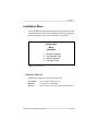
Installation Menu . . . . . . . . . . . . . . . . . . . . . . . . . . . . 4-19
Operator Passwrd . . . . . . . . . . . . . . . . . . . . . . . . . 4-19
Use Operator Pwd . . . . . . . . . . . . . . . . . . . . . . . . . 4-20
Admin Password . . . . . . . . . . . . . . . . . . . . . . . . . . 4-20
Use Admin Pwd . . . . . . . . . . . . . . . . . . . . . . . . . . . 4-20
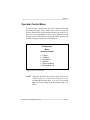
Operator Control Menu . . . . . . . . . . . . . . . . . . . . . . . 4-21
Copies. . . . . . . . . . . . . . . . . . . . . . . . . . . . . . . . . . . 4-22
Collation. . . . . . . . . . . . . . . . . . . . . . . . . . . . . . . . . 4-22
Orientation . . . . . . . . . . . . . . . . . . . . . . . . . . . . . . . 4-22
Inputbin . . . . . . . . . . . . . . . . . . . . . . . . . . . . . . . . . 4-23
Chain Inputbins . . . . . . . . . . . . . . . . . . . . . . . . . . . 4-23
Multipurpose Sz. . . . . . . . . . . . . . . . . . . . . . . . . . . 4-23
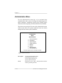
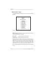
Administration Menu . . . . . . . . . . . . . . . . . . . . . . . . . 4-24
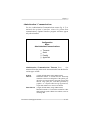
Administration / Communications . . . . . . . . . . . . 4-25
Administration / Communications / Timeouts 4-25
Administration / Communications / Serial . . . . 4-26
Administration / Communications / Parallel . . 4-29
Administration / Communications / AppleTalk 4-30
Administration / Emulations . . . . . . . . . . . . . . . . . 4-32
Administration / Emulations / ESP Default
Emul . . . . . . . . . . . . . . . . . . . . . . . . . . . . . . . 4-32
Administration / Emulations / HP-GL . . . . . . . 4-32
Administration / Emulations / HP PCL 4 . . . . . 4-35
Administration / Emulations / PostScript . . . . . 4-36
Administration / Special Pages . . . . . . . . . . . . . . . 4-37
Administration / Startup Options. . . . . . . . . . . . . . 4-39
v
Administration /Memory . . . . . . . . . . . . . . . . . . . .
Quick Config. . . . . . . . . . . . . . . . . . . . . . . . . . .
K Mem for Spool . . . . . . . . . . . . . . . . . . . . . . .
K Mem for PS Heap . . . . . . . . . . . . . . . . . . . . .
K Mem PS Fonts . . . . . . . . . . . . . . . . . . . . . . . .
K Mem Emulation. . . . . . . . . . . . . . . . . . . . . . .
K Mem Emul Temp . . . . . . . . . . . . . . . . . . . . .
K Mem Display. . . . . . . . . . . . . . . . . . . . . . . . .
K Mem Framebuff . . . . . . . . . . . . . . . . . . . . . .
K Disk Cache . . . . . . . . . . . . . . . . . . . . . . . . . .
MB Printer Mem . . . . . . . . . . . . . . . . . . . . . . . .
Administration / Engine. . . . . . . . . . . . . . . . . . . . .
Image Alignment. . . . . . . . . . . . . . . . . . . . . . . .
Default Paper . . . . . . . . . . . . . . . . . . . . . . . . . .
Inputbin 1 Name . . . . . . . . . . . . . . . . . . . . . . . .
Inputbin 2 Name . . . . . . . . . . . . . . . . . . . . . . . .
Inputbin 3 Name . . . . . . . . . . . . . . . . . . . . . . . .
Outputbin 1 Name. . . . . . . . . . . . . . . . . . . . . . .
Def Resolution . . . . . . . . . . . . . . . . . . . . . . . . .
Gamma Correction . . . . . . . . . . . . . . . . . . . . . .
Enable Buzzer . . . . . . . . . . . . . . . . . . . . . . . . . .
Page Recovery. . . . . . . . . . . . . . . . . . . . . . . . . .
Toner Out Act. . . . . . . . . . . . . . . . . . . . . . . . . .
Man Feed Timeout . . . . . . . . . . . . . . . . . . . . . .
Administration / Miscellaneous. . . . . . . . . . . . . . .
Restore Defaults . . . . . . . . . . . . . . . . . . . . . . . .
Keypad Language . . . . . . . . . . . . . . . . . . . . . . .
Administration /Disk Operations. . . . . . . . . . . . . .
Install Option. . . . . . . . . . . . . . . . . . . . . . . . . . .
Remove Option . . . . . . . . . . . . . . . . . . . . . . . . .
Format Disk. . . . . . . . . . . . . . . . . . . . . . . . . . . .
Collation . . . . . . . . . . . . . . . . . . . . . . . . . . . . . .
Spool Overflow . . . . . . . . . . . . . . . . . . . . . . . . .
Configuring Optional Features . . . . . . . . . . . . . . . . . .
vi
4-41
4-42
4-42
4-43
4-43
4-43
4-43
4-44
4-44
4-44
4-45
4-46
4-46
4-47
4-47
4-47
4-47
4-47
4-48
4-48
4-48
4-48
4-48
4-48
4-49
4-49
4-49
4-50
4-51
4-51
4-51
4-51
4-52
4-52
Chapter 5
Daily Operations
Introduction. . . . . . . . . . . . . . . . . . . . . . . . . . . . . . . . . . 5-1
Using Print Media. . . . . . . . . . . . . . . . . . . . . . . . . . . . . 5-1
Page Sizes and Imageable Regions . . . . . . . . . . . . . 5-1
Working Within Imageable Regions . . . . . . . . . 5-2
Page Margins . . . . . . . . . . . . . . . . . . . . . . . . . . . . . . 5-2
Paper . . . . . . . . . . . . . . . . . . . . . . . . . . . . . . . . . . . . . . . 5-3
Storing Paper . . . . . . . . . . . . . . . . . . . . . . . . . . . . . . 5-3
Loading the 250-Sheet Paper Cassette . . . . . . . . . . 5-3
Loading Print Media in the Multipurpose Tray. . . 5-10
Printing on Both Sides . . . . . . . . . . . . . . . . . . . 5-17
Transparencies . . . . . . . . . . . . . . . . . . . . . . . . . . . . . . 5-18
Storing Transparencies . . . . . . . . . . . . . . . . . . . . . 5-18
Loading Transparencies in the Paper Tray . . . . . . 5-18
Labels . . . . . . . . . . . . . . . . . . . . . . . . . . . . . . . . . . . . . 5-19
Storing Labels . . . . . . . . . . . . . . . . . . . . . . . . . . . 5-19
Loading Labels in the Multipurpose Tray . . . . . . . 5-20
Paper Cassette Chaining . . . . . . . . . . . . . . . . . . . . . . . 5-20
Clearing Media Jams . . . . . . . . . . . . . . . . . . . . . . . . . 5-22
Locating Print Media Jams . . . . . . . . . . . . . . . . . . 5-23
Clearing Front Inside Area Jams . . . . . . . . . . . . . 5-24
Clearing Paper Cassette Area Jams . . . . . . . . . . . 5-27
Clearing Front Upper Door Area Jams . . . . . . . . . 5-28
Clearing Multipurpose Tray Area Jams . . . . . . . . 5-29
Replacing the Toner Cartridge . . . . . . . . . . . . . . . . . . 5-30
Installing the Toner Cartridge . . . . . . . . . . . . . . . . 5-33
Collating Output . . . . . . . . . . . . . . . . . . . . . . . . . . . . . 5-39
Printing a Status Page . . . . . . . . . . . . . . . . . . . . . . . . . 5-41
Cancelling a Print Job. . . . . . . . . . . . . . . . . . . . . . . . . 5-43
Caring for the Printer . . . . . . . . . . . . . . . . . . . . . . . . . 5-45
Handling the Printer. . . . . . . . . . . . . . . . . . . . . . . . 5-45
Cleaning the Printer . . . . . . . . . . . . . . . . . . . . . . . . 5-46
Cleaning the Transparent Sheet Area . . . . . . . . 5-46
vii
Chapter 6
Print Quality
Introduction. . . . . . . . . . . . . . . . . . . . . . . . . . . . . . . . . .
About Print Density . . . . . . . . . . . . . . . . . . . . . . . . . . .
About Gamma Correction . . . . . . . . . . . . . . . . . . . . . .
Terms . . . . . . . . . . . . . . . . . . . . . . . . . . . . . . . . . . . .
Gray Levels . . . . . . . . . . . . . . . . . . . . . . . . . . . . .
Halftone. . . . . . . . . . . . . . . . . . . . . . . . . . . . . . . .
Screen Frequency . . . . . . . . . . . . . . . . . . . . . . . .
Screen Angle . . . . . . . . . . . . . . . . . . . . . . . . . . . .
Gamma Correction Concept . . . . . . . . . . . . . . . . . .
Gamma Correction Application. . . . . . . . . . . . . . . .
Chapter 7
6-1
6-1
6-3
6-3
6-3
6-3
6-4
6-5
6-5
6-7
Professional Printing
Introduction. . . . . . . . . . . . . . . . . . . . . . . . . . . . . . . . . . 7-1
About Typefaces and Fonts . . . . . . . . . . . . . . . . . . . . . 7-1
Typeface Classification . . . . . . . . . . . . . . . . . . . . . . 7-2
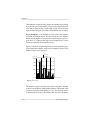
Resident PostScript Fonts . . . . . . . . . . . . . . . . . . . . 7-3
HP PCL Fonts . . . . . . . . . . . . . . . . . . . . . . . . . . . . . 7-6
PostScript Typeface Sampler. . . . . . . . . . . . . . . . . . 7-7
Page Design . . . . . . . . . . . . . . . . . . . . . . . . . . . . . . . . 7-10
Point Size . . . . . . . . . . . . . . . . . . . . . . . . . . . . . . . . 7-11
Pitch . . . . . . . . . . . . . . . . . . . . . . . . . . . . . . . . . . . . 7-12
Monospacing . . . . . . . . . . . . . . . . . . . . . . . . . . . . . 7-12
Proportional Spacing . . . . . . . . . . . . . . . . . . . . . . . 7-12
Character Set . . . . . . . . . . . . . . . . . . . . . . . . . . . . . 7-13
Orientation . . . . . . . . . . . . . . . . . . . . . . . . . . . . . . 7-13
Stroke Weight . . . . . . . . . . . . . . . . . . . . . . . . . . . . 7-13
Italic and Oblique Forms . . . . . . . . . . . . . . . . . . . 7-14
Bibliography . . . . . . . . . . . . . . . . . . . . . . . . . . . . . . . . 7-15
Chapter 8
Printer Options
Introduction. . . . . . . . . . . . . . . . . . . . . . . . . . . . . . . . . . 8-1
Additional Paper Cassettes . . . . . . . . . . . . . . . . . . . . . . 8-1
About the Paper Feeder . . . . . . . . . . . . . . . . . . . . . . . . 8-3
viii
Unpacking the Paper Feeder . . . . . . . . . . . . . . . . . . 8-3
Installing the Paper Feeder . . . . . . . . . . . . . . . . . . . 8-3
Removing the Paper Feeder. . . . . . . . . . . . . . . . . . 8-10
About the Cassette Supporter . . . . . . . . . . . . . . . . . . . 8-10
Unpacking the Cassette Supporter. . . . . . . . . . . . . 8-11
Installing the Cassette Supporter . . . . . . . . . . . . . . 8-11
Removing the Cassette Supporter . . . . . . . . . . . . . 8-15
Dual Paper Cassettes. . . . . . . . . . . . . . . . . . . . . . . . . . 8-16
Loading the 500-Sheet Paper Cassette . . . . . . . . . 8-17
Font and Emulation Cards . . . . . . . . . . . . . . . . . . . . . 8-21
Using Font and Emulation Cards. . . . . . . . . . . . . . 8-21
Removing Font and Emulation Cards . . . . . . . . . . 8-22
Security Cards. . . . . . . . . . . . . . . . . . . . . . . . . . . . . . . 8-23
Removing the Printer and Controller Board Covers . 8-28
Replacing the Printer and Controller Board Covers . 8-32
SIMMs . . . . . . . . . . . . . . . . . . . . . . . . . . . . . . . . . . . . 8-35
Installing a SIMM . . . . . . . . . . . . . . . . . . . . . . . . . 8-35
Removing a SIMM . . . . . . . . . . . . . . . . . . . . . . . 8-38
Optional Network Interface Assembly Kit. . . . . . . . . 8-40
Installing an Optional Network Interface . . . . . . . 8-40
Using an Optional Network Interface . . . . . . . . . . 8-43
Centronics to Dataproducts Conversion. . . . . . . . . . . 8-44
External Hard Disks . . . . . . . . . . . . . . . . . . . . . . . . . . 8-48
Identifying Hard Disks. . . . . . . . . . . . . . . . . . . . . . 8-49
Installing an Optional Font or Emulation . . . . . . . 8-51
Removing an Optional Font or Emulation . . . . . . 8-53
Chapter 9
Troubleshooting
Introduction. . . . . . . . . . . . . . . . . . . . . . . . . . . . . . . . . .
Preventing Print Media Jams . . . . . . . . . . . . . . . . . . . .
Status Messages . . . . . . . . . . . . . . . . . . . . . . . . . . . . . .
PostScript Error with Error Handler Enabled. . .
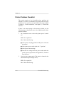
Printer Problem Checklist. . . . . . . . . . . . . . . . . . . . . . .
IBM PC and Compatible Computer Checklist . . . .
Apple Macintosh Checklist . . . . . . . . . . . . . . . . . . .
Other Common Printer Problems . . . . . . . . . . . . . . . . .
9-1
9-1
9-2
9-5
9-6
9-8
9-9
9-9
ix
Data Indicator Stays Lit . . . . . . . . . . . . . . . . . . . . . . 9-9
No Start-up Page . . . . . . . . . . . . . . . . . . . . . . . . . . 9-10
Printer Resets . . . . . . . . . . . . . . . . . . . . . . . . . . . . . 9-11
Blank Pages . . . . . . . . . . . . . . . . . . . . . . . . . . . . . . 9-11
Not All Pages Print . . . . . . . . . . . . . . . . . . . . . . . . 9-12
Paper Jam Message Stays On . . . . . . . . . . . . . . . . 9-12
PostScript Emulation Job Does Not Print . . . . . . . 9-12
Trouble Printing PostScript Files. . . . . . . . . . . . . . 9-12
Multiple Pages Problem. . . . . . . . . . . . . . . . . . . . . 9-13
Limit Check Error on a Macintosh . . . . . . . . . . . . 9-13
Emulation Error . . . . . . . . . . . . . . . . . . . . . . . . . . . 9-13
Binary Data Printing Problem . . . . . . . . . . . . . . . . 9-13
Printer Does Not Print 600 dpi . . . . . . . . . . . . . . . 9-14
Paper Size Mismatch . . . . . . . . . . . . . . . . . . . . . . . 9-14
Image Orientation Problem . . . . . . . . . . . . . . . . . . 9-14
Ledger Versus 11 x 17" Problem. . . . . . . . . . . . . . 9-15
End-of-Document (EOD) Command Problems . . 9-15
General Print Quality Problems . . . . . . . . . . . . . . . . . 9-16
Specific Print Quality Problems . . . . . . . . . . . . . . . . . 9-16
White or Light Lines . . . . . . . . . . . . . . . . . . . . . . . 9-17
Light Image (Entire Page) . . . . . . . . . . . . . . . . . . . 9-17
Dark Image (Entire Page) . . . . . . . . . . . . . . . . . . . 9-17
Black Image (Entire Page). . . . . . . . . . . . . . . . . . . 9-17
Stain along the Edge of the Page . . . . . . . . . . . . . . 9-18
Stains on the Back of the Page . . . . . . . . . . . . . . . 9-18
Image Smears when Rubbed . . . . . . . . . . . . . . . . . 9-18
Placing a Service Call. . . . . . . . . . . . . . . . . . . . . . . . . 9-18
Appendix A
Cable Pinouts
AppleTalk . . . . . . . . . . . . . . . . . . . . . . . . . . . . . . . . . . .
Centronics Parallel . . . . . . . . . . . . . . . . . . . . . . . . . . . .
Notes to the Centronics Parallel Cable Pinouts
Table . . . . . . . . . . . . . . . . . . . . . . . . . . . . . . . . . .
Dataproducts Parallel . . . . . . . . . . . . . . . . . . . . . . . . . .
Serial . . . . . . . . . . . . . . . . . . . . . . . . . . . . . . . . . . . . . . .
x
A-1
A-2
A-3
A-4
A-5
IBM PC/XT, PC/AT, and Compatible Computers. . . . A-6
Appendix B
Technical Specifications
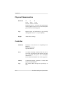
Print Engine . . . . . . . . . . . . . . . . . . . . . . . . . . . . . . . . .
Physical Characteristics . . . . . . . . . . . . . . . . . . . . . . . .
Controller . . . . . . . . . . . . . . . . . . . . . . . . . . . . . . . . . . .
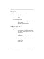
SIMMs . . . . . . . . . . . . . . . . . . . . . . . . . . . . . . . . . . . . .
Interfaces . . . . . . . . . . . . . . . . . . . . . . . . . . . . . . . . . . .
SCSI Hard Disk Drives. . . . . . . . . . . . . . . . . . . . . . . . .
Electrical . . . . . . . . . . . . . . . . . . . . . . . . . . . . . . . . . . . .
Environmental Requirements . . . . . . . . . . . . . . . . . . . .
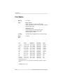
Print Media . . . . . . . . . . . . . . . . . . . . . . . . . . . . . . . . . .
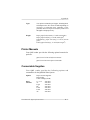
Printer Manuals. . . . . . . . . . . . . . . . . . . . . . . . . . . . . . .
Consumable Supplies . . . . . . . . . . . . . . . . . . . . . . . . . .
How Consumables Affect Your Warranty . . . . . . . . . .
Appendix C
Character Encoding Tables
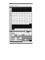
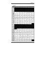
Character Encoding Tables . . . . . . . . . . . . . . . . . . . . .
Standard Encoding. . . . . . . . . . . . . . . . . . . . . . . . . .
Symbol . . . . . . . . . . . . . . . . . . . . . . . . . . . . . . . . . . .
ITC Zapf Dingbats . . . . . . . . . . . . . . . . . . . . . . . . . .
Appendix D
B-1
B-2
B-2
B-3
B-4
B-4
B-5
B-5
B-6
B-7
B-7
B-8
C-1
C-2
C-3
C-4
QMS Customer Support
QMS Customer Support . . . . . . . . . . . . . . . . . . . . . . . . D-1
QMS World-wide Offices . . . . . . . . . . . . . . . . . . . . . . D-4
Appendix E
Document Option Commands
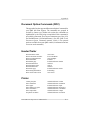
Document Option Commands (DOC) . . . . . . . . . . . . .
Header/Trailer. . . . . . . . . . . . . . . . . . . . . . . . . . . . . . . .
Printer . . . . . . . . . . . . . . . . . . . . . . . . . . . . . . . . . . . . . .
HP-GL Emulation . . . . . . . . . . . . . . . . . . . . . . . . . . . . .
HP PCL Emulation . . . . . . . . . . . . . . . . . . . . . . . . . . . .
E-1
E-1
E-1
E-2
E-2
xi
PostScript Emulation . . . . . . . . . . . . . . . . . . . . . . . . . . E-2
Appendix F
Additional Technical Information
Introduction. . . . . . . . . . . . . . . . . . . . . . . . . . . . . . . . . . F-1
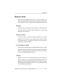
Memory. . . . . . . . . . . . . . . . . . . . . . . . . . . . . . . . . . . . . F-1
QMS Memory Management. . . . . . . . . . . . . . . . . . . . . F-2
Memory Terms . . . . . . . . . . . . . . . . . . . . . . . . . . . . . . . F-3
Memory . . . . . . . . . . . . . . . . . . . . . . . . . . . . . . . . . . F-3
Memory Clients . . . . . . . . . . . . . . . . . . . . . . . . . . . . F-3
Excess Memory Client. . . . . . . . . . . . . . . . . . . . . . . F-3
Storage . . . . . . . . . . . . . . . . . . . . . . . . . . . . . . . . . . . F-3
ROM (Read Only Memory). . . . . . . . . . . . . . . . . . . F-4
RAM (Random Access Memory) . . . . . . . . . . . . . . F-4
RAM Disk . . . . . . . . . . . . . . . . . . . . . . . . . . . . . . . . F-4
SCSI (Small Computer System Interface). . . . . . . . F-4
Non-volatile Memory . . . . . . . . . . . . . . . . . . . . . . . F-5
Volatile Memory . . . . . . . . . . . . . . . . . . . . . . . . . . . F-5
Physical Memory . . . . . . . . . . . . . . . . . . . . . . . . . . . F-5
Virtual Memory . . . . . . . . . . . . . . . . . . . . . . . . . . . . F-5
Spool (Simultaneous Print Operations On Line) . . F-6
Evaluation of Your Printing Environment . . . . . . . . . . F-6
Evaluation Questions . . . . . . . . . . . . . . . . . . . . . . . . F-6
Quick Configuration . . . . . . . . . . . . . . . . . . . . . . . . . . . F-7
Memory Clients . . . . . . . . . . . . . . . . . . . . . . . . . . . . . . F-8
Frame Buffer . . . . . . . . . . . . . . . . . . . . . . . . . . . . . . F-9
Calculating the Frame Buffer Size . . . . . . . . . . F-10
Special Considerations . . . . . . . . . . . . . . . . . . . F-10
Display List . . . . . . . . . . . . . . . . . . . . . . . . . . . . . . F-11
PostScript Font Cache . . . . . . . . . . . . . . . . . . . . . . F-11
PS Heap . . . . . . . . . . . . . . . . . . . . . . . . . . . . . . . . . F-12
Emulation . . . . . . . . . . . . . . . . . . . . . . . . . . . . . . . . F-13
Temporary Emulation . . . . . . . . . . . . . . . . . . . . . . F-14
Spool Buffers . . . . . . . . . . . . . . . . . . . . . . . . . . . . . F-14
Disk Cache . . . . . . . . . . . . . . . . . . . . . . . . . . . . . . . F-15
MB Printer Mem . . . . . . . . . . . . . . . . . . . . . . . . . . F-15
xii
System Memory. . . . . . . . . . . . . . . . . . . . . . . . . . .
Hard Disk Management . . . . . . . . . . . . . . . . . . . . . . .
Virtual Memory Support . . . . . . . . . . . . . . . . . . . .
Spooling Overflow . . . . . . . . . . . . . . . . . . . . . .
Collation . . . . . . . . . . . . . . . . . . . . . . . . . . . . . .
Specific Printing Environments Examples. . . . . . . . .
Example . . . . . . . . . . . . . . . . . . . . . . . . . . . . . . . .
End Job Mode on Your QMS 860 Printer . . . . . . . . .
Common Reasons to Use End Job Mode . . . . . . .
Using the EOD Commands . . . . . . . . . . . . . . . . . .
Setting the End Job Mode for the Serial and
Parallel Protocols . . . . . . . . . . . . . . . . . . . . . . .
Stand-Alone PC . . . . . . . . . . . . . . . . . . . . . . . .
PC Print Server . . . . . . . . . . . . . . . . . . . . . . . . .
Other Print Queuing Systems . . . . . . . . . . . . .
How to Set the End Job Mode via the Control
Panel . . . . . . . . . . . . . . . . . . . . . . . . . . . . . . . . .
Adding an EOD Command to Your File . . . . . . . .
Creating a Network Job Separator. . . . . . . . . . . . .
PS Protocol . . . . . . . . . . . . . . . . . . . . . . . . . . . . . . . . .
Advantages. . . . . . . . . . . . . . . . . . . . . . . . . . . . . . .
Implementation . . . . . . . . . . . . . . . . . . . . . . . . . . .
HP-GL Emulation Color Encoding Equation. . . . . . .
Appendix G
F-15
F-15
F-16
F-16
F-17
F-17
F-18
F-19
F-20
F-21
F-21
F-22
F-22
F-22
F-22
F-24
F-26
F-26
F-27
F-28
F-28
Manual Notices
Manual Notice . . . . . . . . . . . . . . . . . . . . . . . . . . . . .
Laser Safety . . . . . . . . . . . . . . . . . . . . . . . . . . . . . . .
FCC Compliance . . . . . . . . . . . . . . . . . . . . . . . . . . .
Canadian Users . . . . . . . . . . . . . . . . . . . . . . . . . . . .
Vfg 1046/1984 Conformity Statement . . . . . . . . . .
Bescheinigung des Herstellers/Importeurs . . . . . . .
Declaration of Manufacturer/Importer . . . . . . . . . .
Electronics Emissions . . . . . . . . . . . . . . . . . . . . . . .
Colophon . . . . . . . . . . . . . . . . . . . . . . . . . . . . . . . . .
G-1
G-1
G-1
G-3
G-3
G-3
G-4
G-4
G-4
xiii
Glossary
Index
♦
xiv
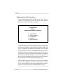
Chapter 1
Introduction
Chapter highlights:
■
Printer overview
■
Documentation overview
■
User’s guide overview
Chapter 1
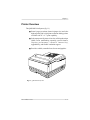
Printer Overview
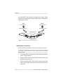
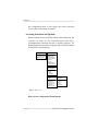
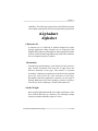
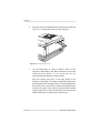
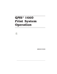
The QMS 860 Print System (fig. 1.1)
■
Prints 8 pages per minute (letter/A4 paper size) and is the
highest quality 600 x 600 print resolution desktop printer
available with 11" x 17" print capability.
■
Is the most powerful printer in its class, offering the unique
QMS Crown multitasking operating system features,
super ior p er f ormance, extensive connectivity,
upgradability, and flexible emulation support.
■
Provides scalable, rotatable fonts for text and graphics.
Fig. 1.1 QMS 860 Print System
Introduction
1-1
Chapter 1
Features
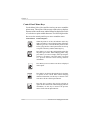
The major features of the QMS 860 Print System are listed below:
■
Exceptional print quality
Produces 8 pages per minute (ppm) of high-quality
letter/A4 output at 600 x 600 print resolution. The QMS
86 0 Prin t Sys tem is a desktop p rin ter with
multiple-resolution capability. The 600 x 600 print
resolution provides smooth dense blacks, fine lines, quality
halftones, and sharp images—excellent for high-quality
photo reproductions.
■
11" x 17"/A3 output at 600 dpi
Provides the frequently requested 11" x 17"/A3 feature
with high-quality 600 dpi output.
■
PostScript Level 2 page description language capability
Allows you to take full advantage of your printer’s high
print resolution. PostScript Level 2 capabilities are
provided in the QMS 860 Print System via the QMS Level
2 page description language, a program which is
compatible with Adobe’s PostScript Level 2 language
while providing additional capabilities. QMS Level 2
supports extensive graphics capabilities to control the
appearance of text, geometric shapes and images, and
improves memory and resource management.
■
Emulation Sensing Processor (ESP) Technology
Allows your printer to recognize and switch to any
incoming printer emulation loaded on the printer. When
your printer is in ESP mode, you can easily print
PostScript, HP PCL 4, or HP-GL documents.
1-2
Introduction
Chapter 1
■
Simultaneous Interface Operation (SIO)
Gives you the ability to have more than one computer
printing to the printer simultaneously. Although many
other printers have multiple interface ports and
automatically designate a “hot port,” only one port actively
receives data at a time. Your QMS 860 Print System is
unique because SIO allows all three interface
ports—AppleTalk, parallel, and serial—to be active and to
receive data at the same time.
You can have more than one computer printing to the
printer. Each interface has an input buffer (which may be
expanded with additional memory) that receives data
while another interface is being used to print. See chapter
3, the “Simultaneous Interface Operation (SIO)” section,
for more information.
The multiple interfaces let you connect to any IBM PC
compatible or Macintosh. The printer also works in many
mainframe computer and minicomputer environments.
■
Crown Architecture
Uses the QMS Crown multitasking operating system that
provides faster processing speeds, networking capability,
and higher printer performance while maintaining
outstanding print quality.
■
3 resident emulations
Supports printing in HP PCL 4, HP-GL 7475A/7550A, and
PostScript Level 1 compatibility mode and PostScript
Level 2 emulations.
Introduction
1-3
Chapter 1
■
RISC-based Intel controller
Produces outstanding print quality and increases
processing speed. The 80960CA RISC microprocessor
operates at a clock speed of 25 Mhz and produces fast
first-page-out performance.
■
39 resident fonts for PostScript emulation printing
Includes 12 typeface families that contain 39 different
fonts. All typeface families have multilingual character
sets.
■
12 megabytes (MB) of resident RAM (Random Access
Memory) upgradable to 32 MB and 4 MB of ROM
(Read-Only Memory)
Allows you to expand your printer’s memory. Additional
RAM provides room for downloading and caching fonts,
and it increases the printer’s buffer (area where data sent
from the computer is stored). Large data-intensive files can
be sent to the printer, freeing the host for other tasks. Your
printer’s ROM includes 2 MB of system and 2 MB of font
memory.
■
Flexible paper handling
Supports paper in 12 different sizes (11" x 17"/A3,
legal/B4, letter/A4, A5, B5, A6, B6, executive, and
universal). The printer supports print media in sizes
ranging from 3.9" to 11.7" (101 mm to 297 mm) wide, and
from 5.8" to 17" (147 mm to 432 mm) long.
■
Optional 250-sheet or 500-sheet paper cassette
Increases the printer’s paper feed capacity. Your printer
comes standard with two 250-sheet paper cassettes:
letter/A4 and 11" x 17"/A3. You can install only one paper
cassette at a time in the printer unless you purchase the
1-4
Introduction
Chapter 1
optional paper feeder that allows you to install dual paper
cassettes, increasing paper feed capacity to 600 sheets
(including the multipurpose tray). Attaching an optional
cassette supporter to the paper feeder allows you to install
a 500-sheet paper cassette, increasing paper feed capacity
to 850 sheets (including the multipurpose tray).
■
Optional font and emulation cards
Increase the printer’s functionality. Extra fonts allow you
to create more distinctive documents. Emulations allow
you to print documents created in a wide range of printer
languages. Fonts (such as the ProCollection for the HP
emulation on your printer) and printer emulations are
contained on small printer circuit boards called cards.
These cards can be plugged into the slots on the right side
of the printer under the output tray. Contact your QMS
vendor for a complete list of available cards.
■
Optional security card
Restricts printer Configuration menu access to users with
valid passwords.
■
Optional network interface
Attaches your printer to other network interfaces, such as
Ethernet and Token-Ring. These interfaces support the
DECnet, TCP/IP, and Novell NetWare protocol. An
additional interface provides greater flexibility and fast
data transfer when working in complex network
environments.
■
Hard disk expandability
Provides hard disk storage for a cache of character
bitmaps, downloaded outline fonts, and other files. The
Introduction
1-5
Chapter 1
resident 25-pin SCSI interface port allows up to 7 external
hard disk drives to be attached to the printer.
■
Convenient control panel operation
Provides a control panel to quickly configure the printer
for your printing needs. The 2-line (16 character-per-line)
panel displays status and error messages in a user-selected
language (English, French, Spanish, or German).
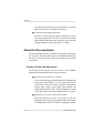
About the Documentation
The documentation provides a window into the many capabilities
of your printer. The more familiar you are with the documentation,
the easier it will be for you to achieve the results you want from
your printer.
Standard Product Documentation
The following section gives you an overview of the standard
product documentation that comes with your printer:
■
QMS 860 Print System User’s Guide
You’re now looking at your detailed guide to installing and
using your printer. Refer to it as you unpack and set up
your printer, connect it to a host, configure it through the
control panel, replace print media, and maintain and
troubleshoot the printer. The “About This Manual” section
later in this chapter, details the contents of the user’s guide.
■
QMS 860 Print System Control Panel Guide
Keep this fold-out card near your printer so you can
quickly get to it when you need a guide to the control panel
or Configuration menu. The card lists Configuration menu
1-6
Introduction
Chapter 1
options and identifies control panel indicators and keys.
For a detailed discussion of the information found on the
Con tro l Panel Guide, see chapter 4, “Printer
Configuration,” in this user’s guide.
■
QMS Crown Network Notes
Refer to this manual for tips on using your QMS 860
printer on a network. It discusses 3Com 3+Open, Banyan
VINES, LAN Manager-based LANs, Novell NetWare,
TCP/IP, UNIX, and VMS/DECnet. In most cases, only
advanced network users and system administrators need
this information.
■
PS Executive Series Utilities
Refer to this documentation as you install and use the PS
Executive Series Utilities software that accompanies your
printer. The PS Executive Series Utilities were designed
specifically for QMS printers. You install this software on
your host and use its user friendly utility programs to
access Macintosh screen fonts, print PC screens, name
your printer, download fonts and emulations, and print
sample files that demonstrate some of your printer’s
capabilities. It includes printer description files required
by your Windows driver and by various applications.A
Windows 3.x driver is also included with this software.
■
Printer Option Documentation
If you purchased a printer option (for example, a network
interface), you may have received separate documentation
for it. See chapter 8 (“Printer Options”) of this manual for
additional option information.
Introduction
1-7
Chapter 1
Optional Purchase Documentation
The following manuals are optional purchases and are included
with your printer only if you ordered them. (If you did not order
them and decide you want them, you can obtain them from your
QMS vendor.)
■
QMS Crown Document Option Commands (optional
purchase)
This is a reference manual that lists and explains Document
Option Commands (DOCs), which provide another way to
control the printer. DOCs are software codes you insert
into documents to enable printer features that cannot be
accessed by your application or your page description
language. Printer command languages (PostScript, HP
PCL, and HP-GL) typically differ in the way they access
and use printer features and capabilities.
Using QMS DOC, you can develop one driver to support
all languages and emulations for your printer. Also, you
can use host network management software to create
customized network printer queues for all users connected
to the printer. In most cases, only advanced users and
system administrators need this information. See appendix
E, “Document Option Commands,” for a list of the DOC
commands supported on the QMS 860 printer.
■
QMS Crown II Technical Reference Manual (optional
purchase)
This manual provides advanced technical information,
including information on communication protocols,
HP-GL emulation, and PostScript emulation. In most
cases, only advanced users and system administrators need
to access this information.
1-8
Introduction
Chapter 1
Related Documentation
Don’t forget that your application documentation, your host
operating system documentation, and your network documentation
all contain useful printing information. See appendix D, “QMS
Customer Support,” to find out how to use the modem or fax
machine to access information on QMS printers.
About This Manual
This user’s guide provides information on how to install, operate,
and maintain the QMS 860 Print System. Each chapter begins with
highlights of its contents. The appendixes contain supplementary
information, the glossary defines printing and computing terms,
and the index helps you to locate specific topics quickly.
Contents
■
Chapter 1 - Introduction
Provides an overview of the printer’s features and the
documentation.
■
Chapter 2 - Printer Installation
Provides information on selecting a printer location and
explains how to unpack and install your printer.
■
Chapter 3 - Printer-Host Interface
Provides information about Simultaneous Interface
Operation (SIO) and Emulation Sensing Processor (ESP)
technology, and explains how to connect to an Apple
Mackintosh or an IBM PC or compatible computer.
Introduction
1-9
Chapter 1
■
Chapter 4 - Printer Configuration
Describes how to operate the control panel and how to use
the menu to configure the printer.
■
Chapter 5 - Daily Operations
Provides information about printing on paper and
transparencies, loading paper, clearing media jams, and
canceling and ending print jobs.
■
Chapter 6 - Print Quality
Provides information on how to improve the print quality.
■
Chapter 7 - Professional Printing
Provides information on typefaces and page design.
■
Chapter 8 - Printer Options
Explains how to install optional printer hardware, such as
the paper cassette, paper feeder, cassette supporter, font
and emulation cards, security cards, and external hard
disks. The installation process for SIMM upgrades and
network interfaces is also described although this
installation should be performed only by a qualified QMS
service technician.
■
Chapter 9 - Troubleshooting
Provides paper jam prevention tips, lists printer error
messages, outlines printer and print quality problems and
solutions, and describes how to place a service call.
■
Appendix A - Cable Pinouts
Provides the recommended pinouts for AppleTalk,
parallel, serial, IBM PC/XT, and IBM PC/AT cables.
1-10
Introduction
Chapter 1
■
Appendix B - Technical Specifications
Provides printer specifications and lists consumable
supplies and replacement parts.
■
Appendix C - Character Encoding Tables
Provides character location tables for the printer’s typeface
families.
■
Appendix D - QMS Customer Support
Provides product sales and support telephone numbers and
describes how to communicate with QMS through the
QMS Bulletin Board, CompuServe, and Q-FAX.
■
Appendix E - Document Option Commands
Lists the Document Option Commands (DOC) supported
by your printer.
■
Appendix F - Additional Technical Information
Explains how to use the End Job Mode feature, provides
advanced information on configuring memory, describes
how PS protocol operates, and provides the equation for
converting HP-GL emulation pen colors to grayscales.
■
Appendix G - Manual Notices
Contains the manual notices, regulatory statements, and
colophon.
■
Glossary
Defines important printing and computing terms.
Introduction
1-11
Chapter 1
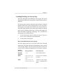
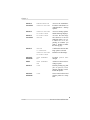
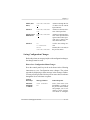
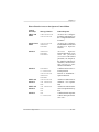
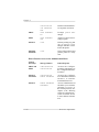
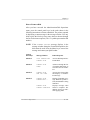
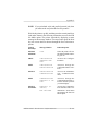
Conventions
The following typographic conventions are used throughout this
manual:
Mixed-Case
Courier
Text you type, and messages and information
displayed on the screen
Mixed-Case
Italic
Courier
Variable text you type; replace the italicized word(s)
with information specific to your printer or computer
UPPERCASE
COURIER
Information displayed in the printer message window
lowercase bold PostScript operators and DOS commands
lowercase italic Variable information in text and PostScript variables
UPPERCASE
File and utility names
↵
Press the Enter key (PC) or Return key (Mackintosh)
^
Press and hold down the Ctrl key (PC)
NOTE: Notes contain tips, extra information, or important
information that deserves emphasis or reiteration.
CAUTION: Cautions present information that you need to know
to avoid equipment damage, process failure, or extreme annoyance.
WARNING! Warnings indicate the possibility of personal in-
jury if a specific procedure is not performed exactly as described in the manual.
♦
1-12
Introduction
Chapter 2
Printer Installation
Chapter highlights:
■
Selecting your printer’s location
■
Unpacking your printer
■
Installing your printer
Chapter 2
Selecting Your Printer’s Location
Your QMS 860 Print System operates in almost any computing
environment. However, when selecting your printer’s location, use
the guidelines in the “Location Requirements” and “Power
Requirements” sections of this chapter.
Location Requirements
Your printer’s locations should
■
Be away from cooling sources, heating sources, extreme
temperature changes, direct sunlight, excessive dust, and
corrosive chemicals or vapors.
■
Be away from any strong electromagnetic field (such as
that created by an air conditioner) and excessive vibration.
■
Have a temperature range of 50° F (10° C) to 90° F
(32.5° C).
■
Have a relative humidity range of 20% to 80%.
■
Be level and capable of supporting the printer weight,
which is about 50 lbs (22.68 kg) for the printer only.
■
Be located an appropriate distance from the host computer,
based on your operating environment—6 feet (1.8 meters)
or less for parallel connection or 25 feet (7.5 meters) or
less for a serial connection.
■
Be well ventilated. Leave space on each side of the printer
for adequate ventilation.
Printer Installation
2-1
Chapter 2
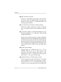
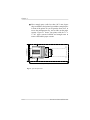
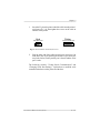
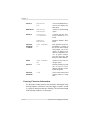
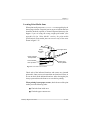
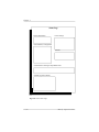
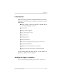
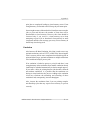
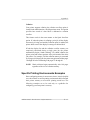
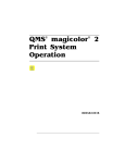
■
Have enough space (with less than .04"/1 mm degree
slope) to hold the four printer legs and have enough space
in front of the printer for you to open the front cover, to
access the multipurpose tray, and to slide out the paper
cassette. Figure 2.1 shows your printer with the 11" x
17"/A3 paper cassette installed and enough room to
remove and load the paper cassette.
25.4"(664mm)
3.4"(85mm)
3.5"(90mm)
3.9"(100mm)
40"(1016mm)
Fig. 2.1 Space Requirements
2-2
Printer Installation
Chapter 2
Power Requirements
Your printer requires a properly grounded AC outlet with a power
range of ± 10 % of the rated voltage. Noise-generating equipment
should not be connected to the same electrical outlet as the printer.
The recommended frequency is 50/60 Hz ±2 Hz.
CAUTION: The supplied power cord is equipped with a 3-wire
grounding plug, for safety purposes. Connect the plug to the proper
grounding-type power outlet.
Unpacking the Printer
Use the following procedure to unpack your printer. The packing
materials—car dboar d, Styrof oam, tape, and shipping
spacers—that protect your printer during shipment must be
removed.
You may want to save the packing materials in case you ever have
to move or ship the printer to a new location.
WARNING! The printer weighs about 50 lbs (22.68 kg). Do
not attempt to lift it by yourself.
ACHTUNG! Der Drucker wiegt ca 23 kg; bitte versuchen Sie
niemals, das Gerät alleine anzuheben oder zu tragen.
CAUTION: If you turn on the printer before all packing materials
are removed, you may damage the printer.
1.
Remove everything except the printer from the shipping
carton.
Printer Installation
2-3
Chapter 2
2.
Lift the printer out of the shipping carton. The printer is heavy,
so two people should be available to lift it. Hold the printer by
the carrying grips located on the bottom of the printer.
3.
Remove the tape from the printer body.
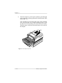
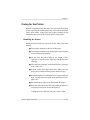
4.
Open the multipurpose tray using both hands (fig. 2.2).
Fig. 2.2 Open the Multipurpose Tray
2-4
Printer Installation
Chapter 2
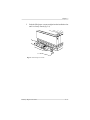
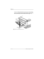
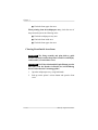
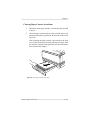
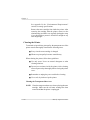
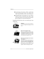
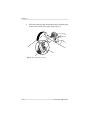
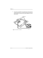
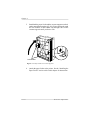
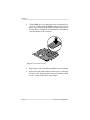
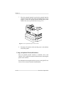
5.
Push up on the release button and open the printer’s front
cover (fig. 2.3).
Release Button
Fig. 2.3 Open the Front Cover
Printer Installation
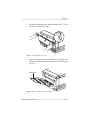
2-5
Chapter 2
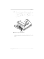
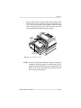
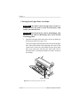
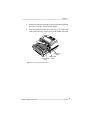
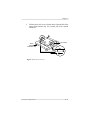
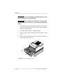
Remove the two orange shipping spacers from inside the
printer (fig. 2.4).
•
•
6.
•
thisRem
•
spa ove
cet Enleve
te cale r cer.
.
•
thisRemo
•
spa ve
cet Enlev
te cal er cer.
e.
Fig. 2.4 Remove the Shipping Spacers
7.
2-6
Remove the packing materials from inside the paper cassette.
Printer Installation
Chapter 2
Checking Shipment Contents
Your shipment consists of the following items:
■
QMS 860 Print System
■
250-sheet 11" x 17" or A3 paper cassette
■
250-sheet letter or A4 paper cassette
■
Rear cassette cover
■
Power cord
■
Warranty card
■
Toner cartridge
■
QMS 860 Print System User’s Guide and binder
■
QMS 860 Print System Control Panel Guide
■
QMS Crown Network Notes
■
PS Executive Series Utilities documentation and software
■
Dataproducts (short-line only) adapter kit (boxed
separately, if ordered)
Make sure that all items are included in your shipment before
installing your printer. If any items are missing or damaged, contact
your QMS vendor. See appendix D, “QMS Customer Support,” for
product sales and support information.
Printer Installation
2-7
Chapter 2
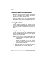
Completing QMS Product Registration
Register your QMS product. In the US call QMS toll-free at (800)
637-8049. In other countries, refer to appendix D, “QMS Customer
Support,” for the appropriate telephone number.
Please take a few minutes to call. Your input helps us to continue
developing new products to address your dynamic printing needs.
Installing Your Printer
Complete all printer installation tasks (installing the toner
cartridge, installing and loading the paper cassette, connecting the
power cord, and printing the start-up page) before installing any
options.
Installing the Toner Cartridge
The toner cartridge contains the toner and photosensitive drum
needed to operate the laser printer. You may purchase additional
cartridges from your QMS vendor.
NOTE: The toner cartridge is sensitive to bright light. Do not
remove the cartridge from its protective bag until you are
ready to install it.
Keep the toner cartridge away from your computer
system. The magnets in the cartridge can damage data,
particularly on your floppy disks.
1.
2-8
Lift the toner cartridge out of its shipping carton, open the
aluminum protective bag, and remove the cartridge.
Printer Installation
Chapter 2
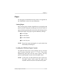
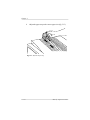
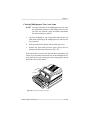
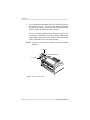
2.
Place the cartridge on a flat, stable surface. Then remove the
black protective sheet (fig. 2.5) and discard it.
Fig. 2.5 Remove the Protective Sheet
Printer Installation
2-9
Chapter 2
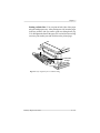
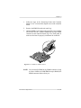
3.
Hold the cartridge with both hands, and gently rock it from
side to side five or six times to distribute the toner (fig. 2.6).
Fig. 2.6 Distribute the Toner
2-10
Printer Installation
Chapter 2
4.
Hold the cartridge in place with one hand, and using your other
hand grasp the orange tab on the right side of the tape seal.
Keep the cartridge parallel with the flat surface and pull the
orange tab (26.4"/67 cm) straight out (fig. 2.7). Discard the
orange tab and tape seal.
Tape Seal
Fig. 2.7 Remove the Tape Seal
Printer Installation
2-11
Chapter 2
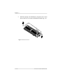
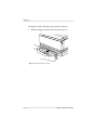
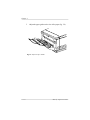
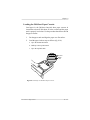
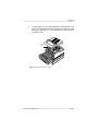
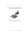
5.
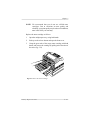
Grasp the green tabs on the toner cartridge and place the
cartridge on the rails inside the printer (fig. 2.8).
Fig. 2.8 Place Toner Cartridge on Rails
2-12
Printer Installation
Chapter 2
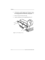
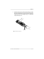
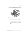
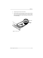
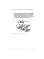
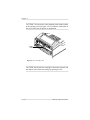
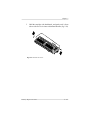
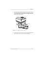
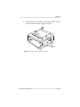
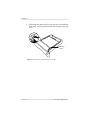
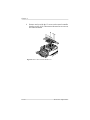
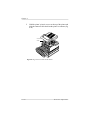
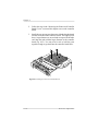
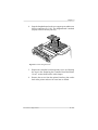
6.
Lift the green tabs slightly and slide the cartridge straight back
into the printer until it is firmly seated (fig. 2.9).
Fig. 2.9 Install the Toner Cartridge
7.
Close the front cover and close the multipurpose tray (if it is
not being used).
NOTE: When the toner cartridge is installed and the printer’s
front cover is only halfway opened or closed, the drum
protective shutters open and the drum surface is exposed
to light. This may deteriorate the drum and reduce print
quality.
Printer Installation
2-13
Chapter 2
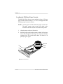
Loading the 250-Sheet Paper Cassette
The QMS 860 Print System comes standard with two 250-sheet
paper cassettes (letter/A4 and 11" x 17"/A3). Load paper in either
250-sheet paper cassette as follows.
NOTE: Use the paper size that matches the paper cassette size.
The paper cassette sends a paper size signal to the
controller when the cassette is inserted into the printer.
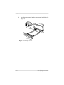
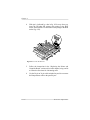
1.
Align the paper stack on a flat surface.
2.
Insert the paper stack into the cassette so that it lies flat, does
not exceed the top limit mark (fig. 2.10), and rests under the
retaining clips. The cassette holds about 250 sheets of 20
pound (75 g/m2) paper.
Top Limit
Bottom
Limit
Fig. 2.10 Load the Paper
2-14
Printer Installation
Chapter 2
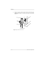
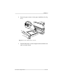
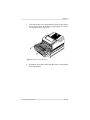
3.
Insert the paper cassette into the paper cassette installation slot
(fig. 2.11).
Fig. 2.11 Insert the Paper Cassette
Printer Installation
2-15
Chapter 2
4.
Push the filled paper cassette straight into the installation slot
until it is firmly seated (fig. 2.12).
Fig. 2.12 Seat the Paper Cassette
2-16
Printer Installation
Chapter 2
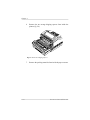
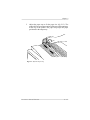
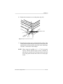
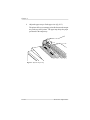
5.
Adjust the paper stop to fit the paper size (fig. 2.13). The
printer delivers your output, print-side down, to the output tray
at the top of the printer. The paper stop keeps the paper
positioned in the output tray.
Fig. 2.13 Adjust the Paper Stop
Printer Installation
2-17
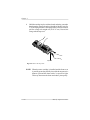
Chapter 2
NOTE: If using the 11" x 17"/A3 or the optional legal/B4 paper
cassette. Place the rear cassette cover on the end of the
cassette at the rear of the printer (fig. 2.14).
Rear Cassette
Cover
Fig. 2.14 Attach the Rear Cassette Cover
2-18
Printer Installation
Chapter 2
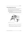
Connecting the Power Cord
The power cord connector is located at the rear of the printer. The
power switch is located at the lower right of the printer.
CAUTION: Make sure that the printer power switch is turned off
(the O is pressed down).
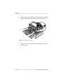
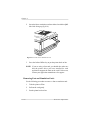
1.
Align the power cord with the connector on the rear of the
printer, and plug the power cord into the connector (fig. 2.15).
Fig. 2.15 Connect the Power Cord
2.
Connect the opposite end of the power cord to a grounded AC
outlet.
3.
Turn on the printer (press | down). After a brief warm-up,
maximum 2 minutes, the printer produces a start-up page.
Printer Installation
2-19
Chapter 2
Printing a Start-up Page
When you turn on the printer, a start-up page prints. This page gives
you an overview of your QMS 860 Print System.
Information printed on the start-up page follows:
■
Printer product name
■
Cumulative number of printed sheets
■
Amount of resident RAM (in bytes)
■
Number of typefaces in ROM
■
Standard interfaces, optional network interfaces,
emulation modes, and printer communication protocol
information
■
Software version number
■
Firmware version number
If the start-up page prints with all the start-up page information,
and the print quality is good, go to chapter 3, “Printer-Host
Interface.”
Otherwise, see chapter 9, “Troubleshooting,” for more information
on printing a start-up page.
WARNING! Turn the printer off and unplug the power cord
before checking for correct printer installation.
ACHTUNG! Schalten Sie bitte den Drucker aus und ziehen
Sie auch den Netzstecker heraus, bevor Sie die korrekte Installation des Druckers überprüfen.
2-20
Printer Installation
Chapter 2
Enabling/Disabling the Start-up Page
Save time and supplies by disabling the start-up page. The system
automatically enables the start-up page to print when the printer is
turned on.
The start-up page contains information that Customer Technical
Support needs to solve your printer problems. If you only need a
start-up page occasionally, use the PS Executive Series Utilities or
the printer control panel to print a status page instead of a start-up
page. See the “Printing a Status Page” section of this chapter, for
more information on printing a status page. You can disable the
start-up page in two different ways:
1.
Use the PS Executive Series Utilities. See the PS Executive
Series Utilities manual for more information.
2.
Use the printer control panel.
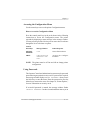
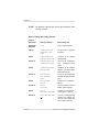
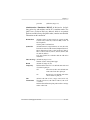
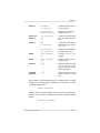
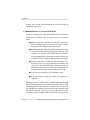
How to Enable/Disable the Start-up Page
Press the control panel keys in the order listed in the following
instructions. The printer responds by displaying a status message
in the message window. You may need to press the Next key one
or more times to advance through the list of selections or options.
Control
Panel Keys
Message Window
Printer Response
ONLINE/
OFFLINE
IDLE
Turns off the indicator.
MENU
CONFIGURATION
OPERATOR CONTROL
Accesses the Configuration menu.
NEXT
CONFIGURATION
ADMINISTRATION
Advances to the Configuration / Administration
menu.
Printer Installation
2-21
Chapter 2
SELECT
and NEXT
ADMINISTRATION
STARTUP OPTIONS
Accesses the Administration menu and advances to
Administration / Startup
Options.
SELECT
STARTUP OPTIONS
DO START PAGE
Accesses Startup Options
and Do Start Page displays.
SELECT
and NEXT
DO START PAGE
OPTION
Accesses Do Start Page
and advances to the Do
Start Page option. OPTION
is either YES or NO, depending on whether you
want to disable or enable
the start-up page.
SELECT
OPTION
IS SELECTED
Confirms that the Do Start
Page option is selected.
STARTUP OPTIONS
DO START PAGE
Returns to Do Start Page.
ONLINE/
OFFLINE
SAVE CHANGES?
NO
Prompts you to save
changes.
NEXT
SAVE CHANGES?
YES
Advances to the next Save
Changes option.
SELECT
IDLE
Finishes printing any print
jobs in process, saves
changes, and idles or reinitializes the printer.
ONLINE/
OFFLINE
IDLE
Turns on the indicator and
puts the printer in a ready
state.
♦
2-22
Printer Installation
Chapter 3
Printer-Host Interface
Chapter highlights:
■
Simultaneous Interface Operation (SIO)
■
Emulation Sensing Processor (ESP) technology
■
Connecting via the AppleTalk port
■
Connecting via the parallel port
■
Connecting via the serial port
Chapter 3
Introduction
Interface is the point at which two elements connect so they can
work together. Printer-host interface is the way a printer connects
to and works with a host (for example, a microcomputer,
minicomputer, mainframe computer, or a network), and it involves
both hardware and software. The way your printer interfaces with
a host depends on many things, including host type, host ports
available, interface cabling, application software, printer
emulations, and printer drivers.
This chapter first explains your printer’s Simultaneous Interface
Operation (SIO) and Emulation Sensing Processor (ESP)
technology. Both of these resident features enhance printer-host
interface. Then this chapter describes how to connect a host to the
printer’s AppleTalk, parallel, or serial port, and test the
communication on that port.
Optional Network Interfaces
In addition to the three standard interfaces—AppleTalk, parallel,
and serial—the QMS 860 Print System has the option of using
another network interface, such as DECnet, TCP/IP, and EtherTalk
on Ethernet networks, and Novell NetWare on Ethernet and
Token-Ring networks. This additional interface option allows
greater flexibility when working in a complex network
environment. See your QMS vendor for a list of available network
interfaces.
If you have purchased an optional network interface for the printer,
see chapter 8, “Printer Options,” for installation instructions, and
see your network and your interface kit documentation for
Printer-Host Interface
3-1
Chapter 3
additional information. See also QMS Crown Network Notes,
which came with your printer.
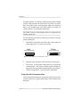
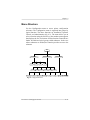
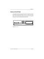
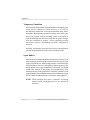
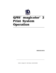
Simultaneous Interface Operation (SIO)
Simultaneous Interface Operation (SIO), a standard feature of
QMS Crown architecture, enables your QMS 860 Print System to
communicate simultaneously with hosts through the AppleTalk,
parallel, serial, and optional network interface (if installed) ports.
In other words, SIO allows you to have more than one host
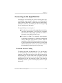
communicating with the printer at one time. These ports are located
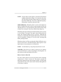
on the interface panel on the back of the printer and are labeled (fig.
3.1).
SCSI
PARALLEL
APPLETALK SERIAL
OPTIONAL I/O
Fig. 3.1 The QMS 860 Print System Interface Ports
NOTE: The printer’s SCSI port, also located on the interface
panel, is used to connect up to seven optional hard disks
to the printer. It is covered by a metal bracket so it is not
confused with the serial port. This metal bracket needs to
be removed before installing a SCSI drive.
3-2
Printer-Host Interface
Chapter 3
ESP Technology
ESP technology is another standard feature of QMS Crown
architecture. ESP technology, which works with most popular
commercially available applications, uses a form of artificial
intelligence to analyze incoming file data and select the appropriate
printer emulation (for example, PostScript emulation, HP-GL
emulation, HP-PCL emulation or another optional emulation) from
those installed on the printer.
The print job is processed without the user having to change printer
switch settings or send software commands to accommodate
different printer emulations.
When your printer is in ESP mode, you can easily print files
prepared for a PostScript printer, an HP LaserJet, or an HP-GL
plotter. The file prints correctly as long as it begins with the
traditional PostScript or HP-GL commands for such items as page
formats and job parameters (number of copies, page margins,
fonts).
The QMS 860 Print System prints almost any file sent in a language
ESP technology understands, whether you have one, two, or more
hosts, and whether you are communicating through a AppleTalk,
parallel, serial, or optional network interface. Most users never
have to change from ESP mode to another mode.
These are a few of the many applications that have been
successfully tested in ESP mode: Adobe Illustrator, Aldus
FreeHand, Aldus PageMaker, AutoCAD, DisplayWrite, Dreams,
Harvard Graphics, Label Matrix, Lotus 1-2-3, Lotus Manuscript,
Microsoft Excel, Microsoft Windows and all Windows
applications, Microsoft Word, MultiMate, PowerPoint, PSPlot,
Printer-Host Interface
3-3
Chapter 3
Sprint, SuperPaint, Ventura Publisher, WingZ, WordPerfect, and
WordStar.
Communication Modes
You can either allow your printer to operate in its default ESP mode
or configure its ports to accept jobs in only a particular emulation
mode (for example, PostScript emulation only, HP PCL only, or
HP-GL emulation only).
Generally, it is best to keep your printer in ESP mode. Since ESP
mode is the factory default, all you have to do to use it initially is
connect your host and printer and then send a file.
If you do want to reconfigure the interface ports for specific
emulations (or if you need to return the printer to ESP mode), the
easiest way is to use the printer’s control panel (the
Administration/Communications menu). Configuring the printer
through the control panel is described in chapter 4, “Printer
Configuration” (and is outlined on your Control Panel Guide).
You can also use PostScript operators to reconfigure printer ports.
The QMS Crown Technical Reference Manual, which is an
optional purchase available from your QMS vendor, contains
information about PostScript operators.
NOTE: We recommend changing printer emulations only on the
serial and parallel ports. The AppleTalk port supports
only PostScript emulation.
3-4
Printer-Host Interface
Chapter 3
Connecting via the AppleTalk Port
Connecting to the LocalTalk port involves basically three steps:
assembling the proper interface cabling (use a LocalTalk-type kit
such as Farallon’s PhoneNET, available from your QMS vendor),
making the connection, and making sure the necessary printing
files are installed on the Macintosh
The AppleTalk port is used to print if
■
Your host is any member of the Apple Macintosh family,
such as the Macintosh SE, II, IIci, IIfx, IIcx, or Quadra.
The instructions in this chapter explain how to connect a
Macintosh to the QMS 860 Print System.
■
Your host is an IBM PC or compatible microcomputer,
workstation, minicomputer, or mainframe computer that
connects through a print network (such as TOPS or
AppleShare) using LocalTalk-type connectors and boxes.
If you are connecting to a host such as these, you may need
additional hardware or software. See your host or network
documentation for details specific to your setup.
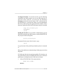
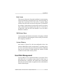
Macintosh Interface Cabling
To connect your printer to a Macintosh (fig. 3.2), you must have
two PhoneNET-type transformer boxes: one with a DIN-8
connector for the printer port and one with a DIN-8 connector for
the Macintosh port. You also need an RJ11 (telephone) cable and
enough terminating resistors to close any open sockets left in the
transformer boxes after the connection is made. (You need two
terminating resistors if you are connecting the printer to a single
Macintosh.)
Printer-Host Interface
3-5
Chapter 3
Your PhoneNET and Macintosh documentation contain further
information on AppleTalk networks and the proper termination of
the transformer boxes.
Printer
Host
DIN-8 Female Port
DIN-8 Female Port
DIN-8 Male Connector
DIN-8 Male Connector
Transformer Boxes
RJ11 Cable
Terminating Resistors
Fig. 3.2 Printer Interface Cables and Connections
Making the Connection
Use the following procedure to connect your printer to the host.
CAUTION: Turn off both the printer and the host before making
the connection.
3-6
1.
Connect the DIN-8 connector from one transformer box to the
printer’s AppleTalk port.
2.
Plug the DIN-8 connector from the other transformer box into
the Macintosh printer port.
3.
Plug one end of the RJ11 cable into the transformer box at the
printer and the other end of the cable into the transformer box
at the host.
Printer-Host Interface
Chapter 3
4.
Insert terminating resistors into any open sockets in the
connector boxes. This ensures proper communication and
helps speed up transmission.
5.
Turn on the printer. A start-up page should print if it has not
been disabled.
Macintosh Printing Software
Once the Macintosh and printer are physically connected by the
LocalTalk cable, you must make sure the necessary printer
software files (for example, drivers and printer description files)
are installed on the Macintosh so it can communicate with the
printer.
PS Executive Series Utilities
We strongly recommend that you now install PS Executive Series
Utilities that came with your printer because it contains, among
other things
■
Printer drivers and printer description files required for
printing from many Macintosh applications
■
Utilities for installing printer-resident screen fonts,
renaming the printer, downloading fonts, and managing
hard disks
■
A Paper Handler utility, which gives Macintosh users
additional paper handling capabilities on multitray printers
■
Font sample files
The PS Executive Series Utilities documentation explains how to
install and use the program.
Printer-Host Interface
3-7
Chapter 3
Macintosh Printer Drivers
A printer driver converts generic commands from applications into
printer-specific commands. You must have a driver designed for
your particular printer to print from your application.
Most Macintosh applications use the Apple LaserWriter driver that
comes with the Macintosh system software. However, we
recommend installing the LaserWriter driver included in PS
Executive Series Utilities because it supports additional page sizes
specific to your printer.
If you are adding the printer to an existing network, the printing
software you need is probably already installed on your Macintosh.
To determine whether you already have the necessary software, do
the following at your Macintosh:
1.
Choose Chooser from the Apple menu. The Chooser window
is displayed.
2.
If a LaserWriter icon appears in the Chooser window, click
the icon to display a list of available printers. Highlight QMS
860 Print System to select your printer; then close the
Chooser window.
If a LaserWriter icon does not appear in the Chooser window,
you must copy the LaserWriter file from PS Executive Series
Utilities onto the System Folder icon on your hard disk or
start-up disk; then close the Chooser window. In order to
install the LaserWriter driver, use the following procedure:
a. Double-click the hard disk or start-up disk icon to display a
window showing the disk contents, including the System Folder.
b. Insert the PS Executive disk called Drivers in a disk drive and
double-click the disk icon to display a window showing the disk
contents, including Paper Handler. Double-click the Paper
3-8
Printer-Host Interface
Chapter 3
Handler icon to display a window containing LaserWriter
(among other things).
c. Copy the LaserWriter file by dragging the icon onto the System
Folder icon on your hard disk or start-up disk. System 6 users
should have the LaserWriter file located in the System Folder.
System 7 users should have the LaserWriter file located in the
Extensions Folder within the System Folder.
NOTE: All Macintosh users on a network must use the same
version of the LaserWriter and Laser Prep files to run
correctly. For example, if the network has a mixture of
LaserWriter 6.0 and 7.0, the printer will experience frequent
reinitialization problems. To check the version number, select
the LaserWriter icon and then hold down the Command key
and press I. The driver version number appears in the Info
window on the second to last line. LaserWriter 7.xx does not
require a Laser Prep file to work correctly with your printer.
The Laser Prep information is located within the LaserWriter
driver itself.
Printer Description Files
In addition to LaserWriter and Laser Prep, many Macintosh
applications, including Aldus PageMaker, Aldus FreeHand, Adobe
Separator, and QuarkXPress, use special printer description files.
PS Executive Series Utilities includes these special files, called
APD (Aldus Printer Description), PPD (PostScript Printer
Description), PDX (Printer Description eXtension), and PDF
(Printer Description File). See “Using the Macintosh Utilities” in
the PS Executive Series Utilities documentation for details.
Adobe Separator uses the PPD file. You have to tell Separator
where the PPD is located on your Macintosh. Check your Adobe
documentation for details.
Printer-Host Interface
3-9
Chapter 3
QuarkXPress uses the file called PDF. Each QMS printer model
requires its own PDF. You must load the PDF in the same folder
as the QuarkXPress application. Check your QuarkXPress
documentation for details.
Aldus PageMaker 4.2 and higher use PPD and PDX files. The
PDX works in conjunction with the standard PPD to expand printer
capabilities. The PPD and PDX must be placed in the PPDs folder
within the Aldus folder inside your System Folder.
Aldus PageMaker 4.01 and earlier use the APD file. The APD
gives PageMaker information specific to your printer type.
Different versions of PageMaker require the APD to be installed
in different ways. Check your PageMaker documentation for
details.
NOTE: In PageMaker 4.0 and higher, if you use these printer
description files and have installed the QMS Paper
Handler, you will not be able to access QMS Paper
Handler features from the default menu. To overcome
this problem, hold down the Option key when selecting
Print from the File menu and use the Apple Driver
window.
Aldus FreeHand 3.0 and higher use PPD and PDX files. The
PDX works in conjunction with the standard PPD to expand
capabilities. The PDX and PPD must be placed in the PPDs folder
inside the Aldus folder inside your System Folder.
Aldus PrePrint uses PPD and PDX files. The PDX works in
conjunction with the standard PPD to expand capabilities. The
PDX and PPD must be placed in the PPDs folder inside the Aldus
folder inside your System Folder.
3-10
Printer-Host Interface
Chapter 3
If you do not install these files for your printer, you can still print
from the applications using other printer options. However, you
may get some error messages informing you to change the name
of the printer, and you may not have all your printer capabilities
available to you.
Testing Macintosh Communication
You can check that the printer selected in the Chooser and the
Macintosh are communicating by printing a directory:
1.
Display a disk or folder window.
2.
Choose Page Setup from the File menu. Select paper size,
printing orientation, and any other necessary options. Then
select OK.
3.
Choose Print Directory or Print Window from the File menu.
A dialog box appears.
4.
Select the printing options you want; then click OK. If no page
prints, check chapter 9, “Troubleshooting.”
Connecting via the Parallel Port
Parallel communication is faster than serial communication, so it
is best if
■
A parallel port is available on your host
■
The host and printer are within 6 feet (approximately 1.8
meters) of each other
■
You print a lot of graphics
Printer-Host Interface
3-11
Chapter 3
A parallel cable has a 36-pin male connector on the printer end and
a 25-pin male connector on the host end. This cable is available
from your QMS vendor. A Dataproducts adapter kit (short-line
only) is also available from your QMS vendor. See chapter 8,
“Printer Options,” for installation instructions.
CAUTION: If you are connecting the printer to a single host, turn
off both systems first.
Use the following procedure to connect your printer to your host
via the parallel port:
1.
Attach the 36-pin printer end of the cable to the parallel port
on the printer (fig. 3.3); then close the clips.
Host
Printer
36-Pin Female Port
25-Pin Female Port
Fig. 3.3 Host and Printer Parallel Interface Ports
2.
Attach the other end of the cable to the host’s parallel port.
3.
If necessary, use the printer control panel to set up parallel
communication. The factory default parallel settings are
appropriate for most parallel communications. See chapter 4,
“Printer Configuration,” if you need more information.
Testing Parallel Communication
To test communication between your printer and host, first create
a short file that ejects a page from the printer. Then send the file to
the printer.
3-12
Printer-Host Interface
Chapter 3
Creating the Test File To create the test file, type the following
commands at the DOS prompt (you can use either uppercase or
lowercase letters; however, you must type the PostScript
showpage operator in lowercase letters). The ↵ symbol means to
press the Enter key. To produce the ^D and ^Z, press and hold down
the Ctrl key while you type the appropriate letters (d and z). These
characters signify the end of the file and must always be included.
copy con printest.ps↵
showpage↵
^D^Z↵
Sending the Test File To test parallel communication, type the
following command at the DOS prompt to send the PRINTEST.PS
file you just created to the printer:
print printest.ps↵
If prompted for the name of the list device, type
lpt1↵
or type the name of the parallel port that the printer is connected
to.
If the printer and host are communicating, a blank page ejects from
the printer.
If a blank page does not eject and you typed the file correctly, you
may want to check your AUTOEXEC.BAT file to see if LPT1 (the
parallel port) is being directed to COM1 (the serial port):
1.
If the AUTOEXEC.BAT file contains the line
MODE LPT1:=COM1:
delete it.
Printer-Host Interface
3-13
Chapter 3
2.
Then type
MODE LPT1:,,P
in the AUTOEXEC.BAT file so that print jobs are sent until
the printer accepts them.
3.
Reboot the host and try the communication test again.
See chapter 9, “Troubleshooting,” and refer to your DOS
documentation for more information.
Connecting via the Serial Port
Serial communication is best if
■
A parallel port is not available on your host
■
The host is more than 6 feet (approximately 1.8 meters)
but less than 25 feet (approximately 7.5 meters) from the
printer
■
You want the printer to return information to the host
The standard serial cable has a 25-pin male (DB-25) connector on
the printer end and either a 9-pin female connector or a 25-pin
female connector on the host. See appendix A for pinouts.
CAUTION: Turn off both the printer and the host before making
the connection.
Use the following procedure to connect your printer to your host
via the serial port:
3-14
Printer-Host Interface
Chapter 3
1.
Insert the 25-pin male printer end of the cable into the printer’s
serial port (fig. 3.4); then tighten the screws on the cable to
attach it to the printer.
Host
9-Pin Male Port
Printer
25-Pin Female Port
Fig. 3.4 Host and Printer Serial Interface Ports
2.
Plug the other end of the cable into the host’s serial port. On
some hosts, the 25-pin parallel port and the 25-pin serial port
may look similar, but the parallel port is female and the serial
port is male.
The following sections, “Testing Serial Communication” and
“Changing Serial Port Settings,” explain how to establish serial
communication between the printer and the host.
Printer-Host Interface
3-15
Chapter 3
Testing Serial Communication
Before you can print to the serial port, the printer, host, and
application must all communicate using the same serial port
settings. If your printer is replacing another printer, and if you are
using the same cable to connect it to the host, the host is probably
already configured correctly. However, if the host has not been
connected to a printer before, or if you are using a different cable,
use the information in this section to test the communication
between printer and host.
To test communication between your printer and host, first create
a short file that ejects a page from the printer and then send it to the
printer.
Creating the Test File To create the test file, type the following
commands at the DOS prompt (you can use either uppercase or
lowercase letters; however, you must type the PostScript
showpage operator in lowercase letters). The ↵ symbol means to
press the Enter key. To produce the ^D and ^Z, press and hold down
the Ctrl key while you type the appropriate letters (d and z). These
characters signify the end of the file and must always be included.
copy con printest.ps↵
showpage↵
^D^Z↵
Sending the Test File To test serial communication, type this
command at the DOS prompt to send the PRINTEST.PS file you
just created to the printer:
print printest.ps↵
If prompted for the name of the list device, type
com1↵
3-16
Printer-Host Interface
Chapter 3
If the printer and host are communicating, a blank page ejects from
the printer. If a blank page does not eject and you typed the file
correctly, see chapter 9, “Troubleshooting.” You may also want to
check your AUTOEXEC.BAT file in DOS to make sure that the
printer’s serial port settings match those of the PC. Look for a
command line like this in your AUTOEXEC.BAT file:
MODE COM1: 9600,N,8,1,P
In this example, the serial port settings are 9600 for baud rate, n
(no) parity, 8 data bits, and 1 stop bit. The p stands for infinite retry.
Now check the start-up page, which prints when you turn on the
printer (unless you disabled it). This tells you the current serial port
settings for the printer. If the serial settings (baud rate, parity, data
bits, and stop bits) shown on the start-up page match those in your
AUTOEXEC.BAT file, you need make no further changes. Go to
the section “Special PC Concerns” later in this chapter.
If the printer’s serial port settings are different from your PC’s, you
must make them match. Refer to the following section, “Changing
Serial Port Settings,” to do this.
Changing Serial Parameters
Since your printer is configured at the factory for the most typical
pr inting environments, the ser ial par ameter s in your
AUTOEXEC.BAT file and on the start-up page should be the same.
However, if they differ, you must configure the printer to use the
serial parameters specified in the AUTOEXEC.BAT file.
Press the control panel keys in the order shown in the following
instructions to change the printer’s serial parameters. The printer
responds by displaying a status message in the message window.
Printer-Host Interface
3-17
Chapter 3
You may need to press the Next key one or more times through the
list of selections or options. If you need to change other serial
parameters, refer to chapter 4, “Printer Configuration,” for
complete information.
NOTE: The printer must be off line and idle to change printer
configuration.
How to Access Serial Mode
Control
Panel Keys
3-18
Message Window
Printer Response
ONLINE/
OFFLINE
IDLE
Turns off the indicator and
takes the printer off line.
MENU
CONFIGURATION
OPERATOR CONTROL
Accesses the Configuration menu.
NEXT
CONFIGURATION
ADMINISTRATION
Advances to the Configuration / Administration
menu.
SELECT
ADMINISTRATION
COMMUNICATIONS
Accesses the Configuration / Administration menu
and displays Administration / Communications.
SELECT
COMMUNICATIONS
TIMEOUTS
Accesses the Administration / Communications
menu and displays Administration / Communications / Timeouts.
NEXT
COMMUNICATIONS
SERIAL
Advances through the Administration /Communications menu.
Printer-Host Interface
Chapter 3
SELECT
SERIAL
MODE
Accesses the Administration / Communications /
Serial menu and displays
the Mode option.
How to Change the Baud Rate
NEXT
SERIAL
BAUD RATE
Advances through the Serial options.
SELECT
BAUD RATE
*9600
Accesses the Baud Rate
option and displays the currently selected baud rate.
NEXT
BAUD RATE
RATE
Advances through the
Baud Rate options. (RATE
is any Baud Rate option.)
SELECT
RATE
IS SELECTED
Confirms the selected baud
rate.
SERIAL
BAUD RATE
Returns to the Administration / Communications /
Serial menu. If you are
done changing serial parameters, then go to the
“How to Save Changes”
section later in this chapter
for save changes information.
How to Change the Parity
NEXT
SERIAL
PARITY
Advances through the Administration / Communications / Serial menu.
SELECT
PARITY
*NONE
Accesses the Parity option
and displays the currently
selected parity.
Printer-Host Interface
3-19
Chapter 3
NEXT
PARITY
TYPE
Advances through the Parity options. (TYPE is any
parity option.)
SELECT
TYPE
IS SELECTED
Confirms the selected parity.
SERIAL
PARITY
Returns to the Administration / Communications /
Serial menu. If you are
done changing serial parameters, then go to the
“How to Save Changes”
section later in this chapter
for save changes information.
How to Change Data Bits
3-20
NEXT
SERIAL
DATA BITS
Advances through the Serial menu.
SELECT
DATA BITS
8 BITS
Accesses the Data Bits option and displays the currently selected data bits.
NEXT
DATA BITS
7 BITS
Advances through the Data
Bits options.
SELECT
7 BITS
IS SELECTED
Confirms the selected data
bits.
SERIAL
DATA BITS
Returns to the Administration / Communications /
Serial menu. If you are
done changing serial parameters, then go to the
“How to Save Changes”
section later in this chapter
for save changes information.
Printer-Host Interface
Chapter 3
How to Change Stop Bits
NEXT
SERIAL
STOP BITS
Advances through the Administration / Communications / Serial menu.
SELECT
STOP BITS
1 BIT
Accesses the Stop Bits option, and displays the currently selected stop bits.
NEXT
STOP BITS
2 BITS
Advances through the Stop
Bits options.
SELECT
2 BITS
IS SELECTED
Confirms the selected stop
bits.
STOP BITS
SERIAL
Returns to the Administration / Communications /
Serial menu. If you are
done changing serial parameters, then go to the
“How to Save Changes”
section next in this chapter
for save changes information.
How to Save Changes
ONLINE/
OFFLINE
SAVE CHANGES?
NO
Displays the default Save
Changes option.
NEXT
SAVE CHANGES?
YES
Advances through the Save
Changes options.
SELECT
IDLE
Finishes printing any print
jobs in process, saves
changes, and idles or reinitializes the printer.
ONLINE/
OFFLINE
IDLE
Turns on the indicator and
puts the printer in a ready
state.
Printer-Host Interface
3-21
Chapter 3
To verify the serial parameter changes you just made, turn the
printer off, then back on. Compare the printer’s start-up page to
your AUTOEXEC.BAT file.
Special PC Concerns
PC Printer Drivers
To communicate with your printer, a printer driver that supports
PostScript and the QMS 860 Print System must be installed in your
application.
A printer driver converts generic printer commands from
applications into printer-specific commands. Many applications
have drivers built in, and you only have to choose a driver from a
menu.
If you already use a PostScript-compatible printer, the driver
defined for that printer will work with your new QMS printer, but
you may not be able to access all of the printer’s features. If your
application does not offer a driver for any QMS printers, you can
use a PostScript driver (if you are working in PostScript emulation
or ESP modes), a LaserJet driver (if you are working in HP PCL
emulation or ESP modes), or a HP-GL 7475A or 7550 plotter driver
(if you are working in HP-GL emulation or ESP modes).
However, if your QMS 860 Print System has features your old
printer did not, such as additional resident fonts, you may want to
install a new driver capable of handling these features. If your
application does not offer a multiple-tray printer driver, it may not
support paper tray selection. Any PostScript printer driver
supporting 11" x 17" output ensures that you get basic printer
functions and 11" x 17" capability. To benefit from all the functions
3-22
Printer-Host Interface
Chapter 3
available on your printer, you need to use the QMS 860 Print
System driver.
Sometimes drivers are available from application manufacturers.
Some drivers for QMS printers are also available through the QMS
Corporate Bulletin Board System and through CompuServe; see
appendix D, “QMS Customer Support,” for information.
NOTE: The QMS 860 printer driver, including the Windows
driver, support all printer supported paper sizes, trays,
and cassettes. Depending on your version of Windows
and your printing environment, you may encounter
printing problems with the Windows driver. If so, use
Microsoft’s Windows driver with the WPD file included
with the PS Executive Series Utilities. See the PS
Executive Series Utilities documentation for more
information on the WPD file.
PC Screen Fonts
Screen fonts allow you to see on the screen how your document
looks before it is printed. You may be able to obtain PC screen fonts
from your application manufacturer or from QMS’s electronic fax
system “Q-FAX,” which will fax you a request form to order the
PC screen fonts. (See appendix D, “QMS Customer Support,” for
information.) However, you can use the printer fonts without
having the corresponding screen fonts.
♦
Printer-Host Interface
3-23
Chapter 4
Printer Configuration
Chapter highlights:
■
Printer control panel operation
■
Printer menu structure
Chapter 4
Introduction
Now that you have your QMS 860 Print System set up (chapter 2),
connected to a host computer, and ready to print (chapter 3), you
need to learn more about how to control the printer and the printing
process. This chapter describes the printer’s menu structure, which
you access through the printer’s control panel. The Control Panel
Guide that came with the printer also contains this information, in
summary form. However, you should read this chapter to make
using the Control Panel Guide easier and to become familiar with
your printer’s capabilities.
Control Panel
The control panel keys allow you to configure the printer through
menu selections that control printer operations. The control panel
LED (light emitting diode) indicators and LCD (liquid crystal
display) message window provide information about the printer
and about the status of print jobs. The first part of this chapter
identifies each control panel part and describes its function. You
should read this section to learn how to use the keys and how to
interpret messages and indicators.
Menu Structure
The second part of this chapter describes the menu structure and
lists the default for each option. A default is a preset value for the
most common printing environment.
This chapter provides basic printer configuration information about
all menu options because most users do not have to use the printer’s
Configuration menu often. The QMS Crown Technical Reference
Printer Configuration
4-1
Chapter 4
Manual, which is an optional purchase available from your QMS
vendor, contains more extensive configuration information.
NOTE: The Administration / Miscellaneous menu Restore
Defaults option allows you to restore factory defaults.
See the “Administration/Miscellaneous” section of this
chapter for more information on this option.
Printer Control Panel
The control panel (fig. 4.1) consists of the following parts:
■
Five indicators that display printer status information,
three print engine indicators that display the current input
bin, and a message window that provides configuration
and status information.
■
Seven control panel keys (three function keys and four
menu keys) that allow you to access frequently used printer
options.
Fig. 4.1 Printer Control Panel
4-2
Printer Configuration
Chapter 4
Control Panel Indicators
Five indicators on the control panel display printer status
information:
Flashes when the printer is warming up. Remains on
when the printer is ready to receive a print job and
during printer operation unless an error is encountered.
Lights when the printer requires operator intervention.
This indicator is usually accompanied by a status
message in the message window.
Lights when the printer is receiving data from one or
more of the simultaneous interfaces.
Lights when the printer is on line and ready to accept
and process new print jobs. Pressing it once takes the
printer off line (the indicator is not lighted), making the
printer ready for configuration.
Lights when the Configuration menu is accessed and
remains on until the Online/Offline key is pressed.
Three indicators on the control panel’s print engine diagram show
the current input bin:
Lights when the multipurpose tray is the current input
bin.
Lights when the lower paper cassette is the current
input bin.
Lights when the optional paper cassette is the current
input bin.
Printer Configuration
4-3
Chapter 4
Control Panel Display
The message window provides configuration and status
information.
MESSAGE WINDOW
Displays two lines of text (with 16 characters on each
line) and presents status messages and configuration
menus.
Status messages are displayed by priority. Priority indicates the
severity of the message. The highest priority message displays on
the top line. If a message uses only the top line of the display, the
next highest priority message displays on the bottom line.
However, if either message display exceeds one line, only the
highest priority message is displayed.
When the status associated with a displayed message has changed,
the message is cleared from the window and the next highest
priority message is displayed. See chapter 9, “Troubleshooting,”
for a list of the status messages that display in the message window.
Control Panel Function Keys
The three function keys (Online/Offline, Cancel, and Status Page)
access frequently used printer options. The four menu keys (Menu,
Select, Next, and Previous) access the Configuration menu and
select options. Keep in mind that some of the function keys may
be used in combination with the menu keys.
4-4
Printer Configuration
Chapter 4
NOTE: Always make sure the printer is idle and off line before
making configuration changes. You must take the printer
off line before using the control panel keys (except for
the Online/Offline key, Cancel key, and Status Page key).
If the printer is not idle, jobs may be lost.
Online/Offline Key When the printer is on line, the indicator on
the key is lighted. Press the key once to take the printer off line (the
indicator goes out). You must take the printer off line before using
all other keys except the Cancel key and the Status Page key.
When the printer goes off line, the communication ports are closed,
so no new data is accepted. The engine stops printing when the
printer has finished printing all jobs in process. Although jobs
continue to compile and print using the data already received, a job
may be interrupted, causing it to wait for more incoming data
before printing resumes.
When the printer is off line, pressing the Online/Offline key once
places it back on line. The indicator lights, and the printer is once
again ready to accept and process new print jobs.
NOTE: Use the Menu key to stop the print job cancel or end.
Cancel Key Press this key to cancel a print job or to send an
end-of-job indicator to a print job waiting for incoming data. It is
not necessary to take the printer off line first.
How to Cancel a Print Job
Press the control panel keys in the order shown in the following
instructions to cancel a print job. The printer responds by
displaying a status message in the message window. You may need
to press the Next key one or more times to advance through the list
of selections or options.
Printer Configuration
4-5
Chapter 4
Control
Panel Keys
Message Window
Printer Response
CANCEL
CANCELLING JOB?
YES
Displays the Cancelling
Job confirmation message.
CANCEL or
SELECT
YES
IS SELECTED
Confirms that jobs which
are printing or compiling
data are to be deleted from
the job queue.
CANCELLING JOB
Cancels the first job in the
job queue and displays the
Cancelling Job message
until the job is completely
removed from the printer.
IDLE
Finishes printing any print
jobs in process, saves
changes, and idles or reinitializes the printer.
How To End a Print Job
Press the control panel keys in the order shown in the following
instructions to send an end-of-job indicator. The printer responds
by displaying a status message in the message window. You may
need to press the Next key one or more times to advance through
the list of selections or options.
Control
Panel Keys
CANCEL
4-6
Message Window
Printer Response
WAITING FOR INPUT
END JOB?
Displays this message and
accepts an end-of-job indicator for the currently compiling job if it is the first job
in the job queue and is
waiting for incoming data.
CANCELLING JOB?
YES
Confirms that print jobs are
to be cancelled.
Printer Configuration
Chapter 4
NEXT or
PREVIOUS
CANCELLING JOB?
END JOB
Displays Cancelling Job
End Job confirmation message.
CANCEL or
SELECT
END JOB
IS SELECTED
Confirms that the print jobs
waiting for input are ended.
IDLE
Finishes printing any print
jobs in process, saves
changes, and idles or reinitializes the printer.
Status Page Key Use the Status Page key to print a page listing
the current printer settings. See chapter 5, the “Printing a Status
Page” section, for information on the status page contents. It is not
necessary to take the printer off line to print a status page.
How to Print a Status Page
Press the control panel keys in the order shown in the following
instructions to print a status page. The printer responds by
displaying a status message in the message window. You may need
to press the Next key one or more times to advance through the list
of selections or options.
Control Panel
Message Window
Printer Response
STATUS
PAGE
PRINT STATUS
YES
Displays Print Status confirmation message.
SELECT
YES
IS SELECTED
Confirms that the Status
Page is selected.
PRINTING STATUS
Prints the status page when
the job queue is available
and clears the Printing
Status message.
IDLE
Finishes printing any print
jobs in process, saves
changes, and idles or reinitializes the printer.
Printer Configuration
4-7
Chapter 4
Control Panel Menu Keys
Use the Menu, Select, Next, and Previous keys to move around the
printer menu. The top line of the message window always displays
the name of the current menu, and the bottom line displays the name
of a selection or option within that menu. The following describes
how to use the control panel keys to move around the menu:
Control Panel
Printer Response
When the printer is on line, the indicator on this key
lights. Press the key once to take the printer off line (the
indicator goes out). You must take the printer off line
before going into the control panel menu for all keys
except the Cancel key and the Status Page key.
Press this key to access the Configuration menu after
the printer goes off line. When changing printer setup,
press this key to cancel a change (before pressing the
Select key), to return to a previous menu, or to return
to a previous character when entering character
information.
Press this key to access a menu or to choose a displayed
menu option.
Press this key to advance through the list of selections
or options for the current menu. When changing
character information, use this key to advance to the
next choice for the current input character.
Press this key to return to the previous selection or
option for the current menu. When changing character
information, use this key to return to the previous
choice for the current input character.
4-8
Printer Configuration
Chapter 4
Menu Structure
Use the Configuration menu to access printer configuration
selections. The Configuration menu is organized into groups by
logical function. The three functions are Installation, Operator
Control, and Administration (fig. 4.2). The menu allows you to
select a function using the Select key, then another menu appears
that displays the list of selections for that function. Functions are
further divided into logical groups called submenus. In the case
where submenus are needed, the function provides access to the
submenu.
Idle
Operator Control
Installation
Operator
Passwrd
Use Operator
Pwd
Copies
Communications
Emulations
Collation
Use Admin
Pwd
Admin
Password
Orientation
Special Pages
Administration
Inputbin
Startup Options
Chain
Inputbins
Memory
Multipurpose
Sz
Engine
Miscellaneous
Disk Operations
Fig. 4.2 Configuration Menu
Printer Configuration
4-9
Chapter 4
■
Installation
Use this function to establish passwords for the Operator
Control and Administration menus. This function displays
only when an optional security card is installed.
■
Operator Control
Use this function to maintain document processing options
(number of copies, media type, and paper orientation).
These capabilities are usually handled most efficiently
within specific print jobs since each job has its own
requirements. However, if there is no way of specifying
these options within a job, you may do so from the control
panel.
■
Administration
Use this f unction to maintain host computer
communication information for selecting and configuring
printer emulations, configuring special pages, printing
engine calibration, and configuring hard disks (if
installed).
4-10
Printer Configuration
Chapter 4
Accessing the Configuration Menu
Use the menu keys to access the printer Configuration menu.
How to Access the Configuration Menu
Press the control panel keys in the order shown in the following
instructions to access the Configuration menu. The printer
responds by displaying a status message in the message window.
You may need to press the Next key one or more times to advance
through the list of selections or options.
Control
Panel Keys
Message Window
Printer Response
ONLINE/
OFFLINE
IDLE
Turns off the indicator.
MENU
CONFIGURATION
OPERATOR CONTROL
Accesses the Configuration menu.
NOTE: The printer must be off line and idle to change printer
configuration.
Using Passwords
The Operator Control and Administration menus may be password
protected using an optional security card. If a password is required,
the message window displays ENTER PASSWORD when you use
the Select key to enter the menu. Enter the password or press the
Menu key to return to the menu. See chapter 8, “Printer Options,”
for more information on security cards.
If an invalid password is entered, the message window flashes
INVALID PASSWORD for three seconds and then returns you to
Printer Configuration
4-11
Chapter 4
the Configuration menu. If you specify the correct password,
access to the selected menu is granted.
Accessing Selections and Options
Menus list each selection available within a functional group. For
example, in figure 4.3 the Administration menu has a
Communications submenu that has a Parallel selection. The
Parallel/Emulation selection has options, such as ESP, Hexdump,
PCL4, HP-GL, and PostScript.
Configuration
Administration
❏ Installation
❏ Operator Control
■ Administration
■
❏
❏
❏
❏
❏
❏
❏
Communications
Emulations
Special Pages
Startup Options
Memory
Engine
Miscellaneous
Disk Operations
Administration/
Communications
❏
❏
■
❏
Timeouts
Serial
Parallel
AppleTalk
Communications/
Parallel
Parallel/
Emulation
❏
■
❏
❏
❏
❏
ESP
Hexdump
PCL4
HPGL
PostScript
Mode
Emulation
Min K Spool
Spool Timeout
Data Bits
End Job Mode
Fig. 4.3 Menu Access
How to Select Configuration Menu Options
4-12
Printer Configuration
Chapter 4
Press the control panel keys in the order shown in the following
instructions to select Configuration menu options. The printer
responds by displaying a status message in the message window.
The top line of the message window displays the name of the
current menu, and the second line displays the name of the current
selection. You may need to press the Next key one or more times
to advance through the list of selections or options.
Control
Panel Keys
Message Window
Printer Response
ONLINE/
OFFLINE
IDLE
Turns off the indicator.
MENU
CONFIGURATION
OPERATOR CONTROL
Accesses the Configuration menu.
NEXT
CONFIGURATION
ADMINISTRATION
Advances to the Administration menu.
SELECT
ADMINISTRATION
COMMUNICATIONS
Accesses the Administration menu and displays
Communications.
SELECT
COMMUNICATIONS
TIMEOUTS
Accesses the Administration / Communications
menu and Timeouts displays.
NEXT
COMMUNICATIONS
PARALLEL
Advances to the Administration / Communications
/ Parallel menu
SELECT
PARALLEL
MODE
Accesses the Administration / Communications /
Parallel menu and displays
the Mode selection.
NEXT
PARALLEL
EMULATION
Advances to Parallel /
Emulation.
Printer Configuration
4-13
Chapter 4
SELECT
EMULATION
ESP
Accesses the Emulation selection and displays the
ESP option.
PREVIOUS
EMULATION
POSTSCRIPT
Advances to the PostScript
option.
SELECT
POSTSCRIPT
IS SELECTED
Confirms that the PostScript emulation is selected.
PARALLEL
EMULATION
Returns to Parallel / Emulation.
ONLINE/
OFFLINE
or MENU
SAVE CHANGES?
NO
Exits from the menu (Online/Offline) or returns to
the previous menu (Menu)
and prompts you to save
changes if changes were
made to configuration values. To ignore changes,
press the Select key and
then press Online/Offline.
NEXT
SAVE CHANGES?
YES
Advances to the next save
changes option.
SELECT
IDLE
Finishes printing any print
jobs in process, saves
changes, and idles or reinitializes the printer.
ONLINE/
OFFLINE
IDLE
Turns on the indicator and
puts the printer in a ready
state.
Entering Character Information
Use the printer control panel to enter character information in the
message window. A character is any letter, digit, or symbol. A field
is a group of characters that have meaning. The maximum length
of the message window is 16 characters.
4-14
Printer Configuration
Chapter 4
Entering character information through the control panel is similar
to setting the time and date on a digital watch. You enter one
character at a time. The current input character flashes. Use the
following keys to change the current input character:
Next key
Advances to the next choice for the current input
character.
Previous key
Returns to the previous choice for the current input
character.
Once you have changed the current input character, use the
following keys to move the cursor to the next character:
Select key
Advances the cursor to the next character.
Menu key
Returns the cursor to the previous character.
To exit from the process, press the Select key on the last character
of the input field (the character farthest to the right) or the Menu
key on the first character of the input field (the character farthest
to the left). When you exit, the printer verifies the character
information and confirms it in the message window. You are
returned to the previous menu when the character information is
valid; otherwise, you are returned to the input field. Press the Menu
key to cancel any changes to the character information.
If the current character information is longer than the value that
you need to enter, replace each extra character with a space. The
printer interprets a space at the end of character information as a
blank.
Press the control panel keys in the order shown in the following
instructions to change the HP-GL emulation scaling percent. The
printer responds by displaying a status message in the message
window. You may need to press the Next key one or more times to
advance through the list of selections or options.
Printer Configuration
4-15
Chapter 4
NOTE: An underline indicates the current input character in the
message window.
How to Change the Scaling Percent
Control
Panel Keys
4-16
Message Window
Printer Response
OFFLINE/
ONLINE
IDLE
Turns off the indicator.
MENU
CONFIGURATION
OPERATOR CONTROL
Accesses the Configuration menu.
NEXT
CONFIGURATION
ADMINISTRATION
Advances to the Administration menu.
SELECT
ADMINISTRATION
COMMUNICATIONS
Accesses the Administration / Communications
menu.
NEXT
COMMUNICATIONS
EMULATIONS
Advances to the Administration / Communications
/ Emulations menu.
SELECT
EMULATIONS
ESP DEFAULT
EMUL
Accesses the Emulations
and ESP Default Emul displays.
NEXT
EMULATIONS
HP-GL
Advances to Emulations /
HP-GL.
SELECT
HP-GL
PLOTTER
Accesses HP-GL and the
Plotter option displays.
NEXT
HP-GL
SCALING PERCENT
Advances to the HP-GL /
Scaling Percent option.
SELECT
SCALING PERCENT
100
Accesses Scaling Percent,
displays the Scaling Percent field, and flashes the
current input character.
Printer Configuration
Chapter 4
NEXT (four
times)
SCALING PERCENT
500
Advances through the list
of choices for the current
input character.
SELECT
SCALING PERCENT
500
Advances to the next character of the input field.
SELECT and
PREVIOUS
SCALING PERCENT
500
Advances to the next character of the input field and
replaces the 0 with a space.
(The space changes the
value from 500 to 50).
SELECT
50
IS SELECTED
Verifies the Scaling Percent.
HP-GL
SCALING PERCENT
Returns (after 3 seconds) to
the previous menu.
Saving Configuration Changes
Before the printer can accept print jobs with configuration changes,
the changes must be saved.
How to Save Configuration Menu Changes
Press the control panel keys in the order shown in the following
instructions to save Configuration menu changes. The printer
responds by displaying a status message in the message window.
You may need to press the Next key one or more times to advance
through the list of selections or options.
Control
Panel Keys
ONLINE/
OFFLINE
or MENU
Message Window
Printer Response
SAVE CHANGES?
NO
Exits from menu (Online/Offline) or returns to
the previous menu (Menu)
and prompts you to save
changes when changes
were made to configura-
Printer Configuration
4-17
Chapter 4
tion values. To ignore
changes, press the Select
key and then press Online/Offline.
NEXT
SAVE CHANGES?
YES
Advances to the next save
changes option.
SELECT
IDLE
Finishes printing any print
jobs in process, saves
changes, and idles or reinitializes the printer.
ONLINE/
OFFLINE
IDLE
Turns on indicator and puts
the printer in a ready state.
NOTE: Some Administration menu changes require that the
printer be restarted before they take effect; usually the
printer does this automatically if necessary. However, if
you make configuration changes and they do not take
effect, wait until the current jobs have ended, then try
turning the printer off and on.
4-18
Printer Configuration
Chapter 4
Installation Menu
Use the Installation menu to password-protect the Operator Control
and Administration menus. The Installation menu (fig. 4.4) appears
when an optional security card is installed in your printer.
Configuration
Menu
Installation
❏
❏
❏
❏
Operator Passwrd
Use Operator Pwd
Admin Password
Use Admin Pwd
Fig. 4.4 Installation Menu
Operator Passwrd
Maintains the Operator Control menu password.
Prerequisite
Set Use Operator Passwrd to on.
Operator
Passwrd
(16 characters, default blank)
Password used to access the Operator Control menu.
Printer Configuration
4-19
Chapter 4
Use Operator Pwd
Sets the Use Operator Pwd value.
Use Operator
Pwd
(default off; range on, off)
On
Requires password to access the Operator Control
menu.
Off
Does not require a password to access the Operator
Control menu.
Admin Password
Maintains the Administration menu’s password.
Prerequisite
Set Use Admin Pwd to on.
Admin
Password
(16 characters, default blank)
Password used to access the Administration menu.
Use Admin Pwd
Sets the Use Admin Pwd value.
Use Admin Pwd (default off; range on, off)
4-20
On
Requires a password to access the Operator Control
menu.
Off
Does not require a password to access the Operator
Control menu.
Printer Configuration
Chapter 4
Operator Control Menu
Use the Operator Control menu (fig. 4.5) to maintain document
processing and paper source values. These values are print job
specific and should be specified within the print job. However, if
there is no way of passing these values to your application’s print
program, use the control panel to change the values, print the job,
and then change the values back to their defaults.
Configuration
Menu
Operator Control
❏
❏
❏
❏
❏
❏
Copies
Collation
Orientation
Inputbin
Chain Inputbins
Multipurpose Sz
Fig. 4.5 Operator Control Menu
NOTE: Changing document processing values through the
contr ol panel in a shared environment is not
recommended because there is no way of preventing
other jobs from printing while the default change is in
effect.
Printer Configuration
4-21
Chapter 4
Copies
Maintains the number of copies for each print job.
Copies
(3 digits; default 001; range 001 - 999)
Specifies the number of copies for each print job.
Collation
Arranges multiple copies of a document in sequential order. See
chapter 5, the “Collating Output” section, for more information on
collation. See the “Administration / Disk Operations / Collation”
section, later in this chapter, for information on using collation with
a hard disk.
Collation
(default off; range off, on)
Off
Does not collate multiple copies of a document. Prints
all copies of one page before printing the next page.
On
Collates multiple copies of a document. Prints the
entire copy of a document before printing the next
copy.
Orientation
Maintains the paper orientation.
Orientation
(default portrait; range portrait, landscape)
Specifies the orientation of the image on a page.
Portrait
Places the image from left to right across the narrower
dimension of the page.
Landscape
Places the image from left to right across the wider
dimension of the page.
NOTE: When printing a landscape image, let the application
determine the orientation. If you change the printer’s
orientation setting, your image may not print correctly.
4-22
Printer Configuration
Chapter 4
Inputbin
Maintains the default tray or paper cassette from which paper is
taken. To change the default input bin, select the appropriate input
bin through the printer control panel, then turn the printer off and
back on again.
Inputbin
(default lower (inputbin 2); range multipurpose
(inputbin 1), lower (inputbin 2), optional (inputbin 3)
Specifies the default input bin. Displays an “*” next to
the default input bin.
Chain Inputbins
Maintains the chain input bin value.
Chain
Inputbins
(default on; range on, off)
On
Switches to the next input bin with the same size paper
when the default input bin is empty.
Off
Does not switch input bins. Uses only the default input
bin.
Multipurpose Sz
Maintains the paper size for the multipurpose tray (input bin 1).
Multipurpose Sz (default letter; range letter, B5, B6, A6, A5, universal,
A3, 11 x 17, B4, legal, executive, A4)
Printer Configuration
4-23
Chapter 4
Administration Menu
Use the Administration menu (fig. 4.6) to maintain host
communication values, such as selecting and configuring specific
printer languages, configuring special pages, printing engine
calibration, and configuring external hard disks (when installed).
The printer must restart itself for some of the Administration menu
values to take effect. The options within this menu are seldom
changed after the initial system installation.
Configuration
Menu
Administration
❏
❏
❏
❏
❏
❏
❏
❏
Communications
Emulations
Special Pages
Startup Options
Memory
Engine
Miscellaneous
Disk Operations*
* This option appears only if a hard disk is installed
Fig. 4.6 Administration Menu
4-24
Prerequisite
(To password-protect the menu)
Install optional security card
Set Use Operator Pwd to On
Specify Operator Passwrd
Access
Restricted to users with a valid password when the
menu is password protected.
Printer Configuration
Chapter 4
Administration / Communications
Use the Administration/Communications menu (fig. 4.7) to
maintain the printer’s interface values for printer-host
communications. Optional interface program selections appear
only when installed.
Configuration
Menu
Administration/Communications
Timeouts
❏ Serial
❏ Parallel
❏ AppleTalk
❏
Fig. 4.7 Administration/Communications
Administration / Communications / Timeouts Sets
the
amount of time the printer waits on transmission from the host for
various types of data.
PS Wait
Timeout
(5 digits; default 00030; range 00000-99999)
Maximum number of seconds that the PostScript
emulation waits for incoming data. If the printer goes
idle after 30 seconds and does not print, increase this
timeout. Large print jobs, such those generated by
graphics or computer-aided design applications,
require this number to be increased to 00300.
Emul Timeout
(5 digits; default 00005; range 00000-99999)
Maximum number of seconds that emulations other
than PostScript (such as HP PCL4 or HPGL) wait for
incoming data.
Printer Configuration
4-25
Chapter 4
Job Timeout
(5 digits; default 00000; range 00000-99999)
Maximum number of seconds the printer processes a
print job before it ends the job.
ESP Timeout
(5 digits; default 00003; range 00000-99999)
Maximum number of seconds the printer uses to match
an emulation before printing the job in the default
emulation.
Administration / Communications / Serial Sets th e serial
interface communications values used for printer-host
communications.
Mode
(default interactive; range interactive, noninteractive,
disabled)
Sets the PostScript emulation host mode. You must
turn the printer off and then on again before these
changes take effect.
Interactive
Establishes two-way communication
between the host and the printer.
Noninteractive Establishes one-way communication
from the host to the printer.
Disabled
Turns off serial interface communication with the printer. The printer stops
accepting serial interface print jobs.
Emulation
(default ESP; range ESP, Hexdump, PCL4, HPGL,
PostScript)
Selects the serial interface emulation. Optional
emulations appear, if installed.
Min K Spool
(5 digits; default 00015; range 00000-99999)
Sets the minimum number of kilobytes of system
memory allocated to the serial interface. A 00000 value
does not turn off the serial interface’s spooling buffer.
If the value is 00000, the printer calculates the Min K
Spool value at initialization.
Prerequisite: Value must be less than K Mem for
Spool.
4-26
Printer Configuration
Chapter 4
Spool Timeout (5 digits; default 00030; range 00000-99999)
Maximum number of seconds the interface waits for
data from the host system before terminating a spooled
print job.
End Job Mode (default none; range none, QMS EOD, HP EOD)
Sequences that allow host computers to enforce print
job sequencing without considerations for interacting
timeouts. Enables or disables data stream sensing for
the end-of-document (EOD) command. See appendix
F, “Additional Technical Information,” for details on
how to implement this feature on your QMS 860 Print
System.
None
PostScript ^D (CTRL D) command
QMS EOD
%%EndOfDocument
HP EOD
<ESC>%-12345X
Baud Rate
(default 9600; range 300, 600, 1200, 2400, 4800, 9600,
19200, 38400)
Rate that data is transmitted (bits per second) over the
serial interface.
Parity
(default none; range none, mark, space, odd, even)
Check bit used to identify data transmission errors. The
printer’s parity setting must match the host computer’s
or application’s parity setting.
Ignore Parity
(default off; range on, off)
On
ignores parity
Off
does not ignore parity
Rcv Sw
Flow Ctl
(default XON/XOFF; range XON/XOFF, ETX/ACK,
none)
Software communication protocol used by the printer
to control communication from the host computer.
Xmit Sw
Flow Ctl
(default none; range none, XON/XOFF, ETX/ACK)
Software communication protocol used by the printer
to control communication with the host computer.
Data Bits
(default 8 bits; range 8 bits, 7 bits)
Number of data bits transmitted per character.
Printer Configuration
4-27
Chapter 4
Stop Bits
(default 1 bit; range 1 bit, 2 Bits)
Number of stop bits transmitted per character.
Hdwe Flow
Ctl
Controls the flow of data. All values must be set the
same as those of the host computer.
DSR POL
DSR
DTR POL
DTR
RTS
CTS
PS Protocol
4-28
(default lo; range hi, lo)
(default off; range on, off)
(default lo; range hi, lo)
(default on; range on, off)
(default off; range on, off)
(default off; range on, off)
(default normal; range normal, normal fixed, binary,
binary fixed)
Sets the binary communications protocol (BCP) for
communicating over a serial interface to a PostScript
printer. See appendix F, “Additional Technical
Information,” for more information.
Normal
Enables standard, ASCII hex protocol. Data is sent and received in ASCII
format. This mode is recommended if
you do not print binary data. It was
designed for data in the printable ASCII range. Print jobs can alter the PS
protocol value through PostScript operators.
Normal
Fixed
Enables standard, ASCII hex protocol. Print jobs can not alter this value
through PostScript operators.
Binary
Enables binary communications protocol. Print jobs can alter this value
through PostScript operators. Data in
the printable ASCII range also prints.
Binary
Fixed
Enables binary communications protocol. Print jobs can not alter this
value through PostScript operators.
Data in the printable ASCII range also
prints.
Printer Configuration
Chapter 4
Administration / Communications / Parallel Sets the parallel
interface value used for printer-host communications.
Mode
(default enabled; range enabled, disabled)
Sets the host mode. You must turn the printer off and
then on again before changes take effect.
Enabled
Establishes one-way parallel communication from the host to the printer.
Disabled
Turns off parallel interface communication with the printer. The printer
stops accepting parallel interface print
jobs.
Emulation
(default ESP; range ESP, Hexdump, PCL4, HPGL,
PostScript)
Sets the parallel interface emulation. Optional
emulations appear, only if installed.
Min K Spool
(5 digits; default 00015; range 00000-99999)
Sets the minimum number of kilobytes of system
memory allocated to the parallel interface. A 00000
value does not turn off the spooling buffer for the
parallel interface. If the value is set to 00000, the printer
calculates the Min K Spool at initialization.
Prerequisite: Value must be less than K Mem For
Spool.
Spool Timeout (5 digits; default 00030; range 00000-99999)
Number of seconds the interface waits for data from
the host before terminating a spooled print job.
Data Bits
(default 8 bits; range 7 bits, 8 bits)
Number of data bits transmitted per character.
End Job Mode (default none; range none, QMS EOD, HP EOD)
Sequences that allow host computers to enforce print
job sequencing without considerations for interacting
timeouts. Enables or disables data stream sensing for
the end-of-document (EOD) command. See appendix
F, “Additional Technical Information,” for details on
how to implement this feature on your QMS 860 Print
System.
Printer Configuration
4-29
Chapter 4
PS Protocol
None
PostScript ^D (CTRL D) command
QMS EOD
%%EndOfDocument
HP EOD
<ESC>%-12345X
(default normal; range normal, normal fixed, binary,
binary fixed)
Sets the binary communications protocol (BCP) for
communicating over a parallel interface to a PostScript
printer. See appendix F, “Additional Technical
Information,” for more information.
Normal
Enables standard, ASCII hex protocol. Data is sent and received in ASCII
format. This mode is recommended if
you do not print binary data. It was
designed for data in the printable ASCII range. Print jobs can alter the PS
protocol value through PostScript operators.
Normal
Fixed
Enables standard, ASCII hex protocol. Print jobs can not alter this value
through PostScript operators.
Binary
Enables binary communications protocol. Print jobs can alter this value
through PostScript operators. Data in
the printable ASCII range also prints.
Binary
Fixed
Enables binary communications protocol. Print jobs can not alter this
value through PostScript operators.
Data in the printable ASCII range also
prints.
Administration / Communications / AppleTalk Sets
the
AppleTalk interface values used for printer-host communication.
Mode
4-30
(default enabled; range enabled, disabled) Enables or
disables the communication interface. You must turn
the printer off and back on again before changes take
effect.
Printer Configuration
Chapter 4
Connection
Min K Spool
Enabled
Establishes one-way AppleTalk communication from the host to the
printer.
Disabled
Turns off the AppleTalk interface, and
the printer stops accepting AppleTalk
interface print jobs.
(default conventional; range conventional, spool)
Connection allows you to enable or disable print
spooling.
Conventional
Allows one AppleTalk connection
and accepts only one print job at a
time. If two users send print jobs to the
printer, the workstation belonging to
the first user is unavailable until the
first job has been printed, and the
workstation belonging to the second
user is unavailable until both jobs
have been printed.
Spool
Allows multiple AppleTalk connections and accepts (spools) more than
one print job at a time. Workstations
are available while jobs are printing.
(default 00015; range 00000-99999)
Sets the minimum number of kilobytes of system
memory allocated to the AppleTalk interface.
Prerequisite: value must be less than K Mem For
Spool.
Printer Configuration
4-31
Chapter 4
Administration / Emulations
Use the Administration / Emulations menu (fig. 4.8) to set the
parameters for the available printer emulations. Optional printing
emulations appear only if installed.
Configuration
Menu
Administration/Emulations
❏ ESP Default Emul
❏ HP-GL
❏ HP PCL4
❏ PostScript
Fig. 4.8 Administration/Emulations
Administration / Emulations / ESP Default Emul Sets the ESP
default emulation used when ESP is unable to identify the language
of a print job. This default allows the system administrator to select
alternate default emulations. You must turn the printer off and back
on again for the changes to take effect.
ESP Default
Emul
(default PCL4; range PCL4, HPGL, PostScript)
Optional emulations appear, only if installed.
Administration / Emulations / HP-GL Main tain s H P- GL
emulation values. The QMS Crown Technical Reference Manual,
which is an optional purchase available from your QMS vendor,
contains more detailed information on this emulation.
4-32
Printer Configuration
Chapter 4
Plotter
(default 7550A; range 7550A, 7475A, 7470A,
ColorPro)
HP-GL plotter type.
Scaling Percent (default 100; range 001-150)
Percentage to reduce or enlarge an image.
Origin
Image offset from the plotter’s origin in 0.01"
increments.
X direction
(default 0000; range 0-8500 [8.5"])
Y direction
(default 00000; range 0-11000
[11.00"])
Reverse Image (default off; range off, on)
Inverse of an image.
Off
Prints black image on white background.
On
Prints white image on black background.
Enhanced Mode (default off; range off, on)
Indicator that sets the resolution of a downloaded
character set.
Expand Mode
Paper Type
Off
Uses standard resolution.
On
Turns on enhanced resolution.
(default off; range off, on)
Indicator that expands default scaling points P1 and P2,
hard-clip plotting range, and maximum plotting area.
Off
Uses default scaling points, plotting
range, and plotting area.
On
Turns on expand mode.
(default A; range A, A4, B, A3)
Original image’s paper size.
A
Letter (8.5" x 11")
B
11" x 17"
Printer Configuration
4-33
Chapter 4
Pen 1
Pen 2
Pen 3
Pen 4
Pen 5
Pen 6
Pen 7
Pen 8
A4
210 x 297 mm (closest metric value
for letter)
A3
297 x 420 mm (closest metric value
for 11" x 17")
Width and color for pen 1 of the plotter.
pen width
(default 7 [.7 mm]; range 1-60)
pen color
(default 1; range 1-8)
Width and color for pen 2 of the plotter.
pen width
(default 3 [.3 mm]; range 1-60)
pen color
(default 2; range 1-8)
Width and color for pen 3 of the plotter.
pen width
(default 3 [.3 mm]; range 1-60)
pen color
(default 3; range 1-8)
Width and color for pen 4 of the plotter.
pen width
(default 3 [.3 mm]; range 1-60)
pen color
(default 4; range 1-8)
Width and color for pen 5 of the plotter.
pen width
(default 3 [.3 mm]; range 1-60)
pen color
(default 5; range 1-8)
Width and color for pen 6 of the plotter.
pen width
(default 3 [.3 mm]; range 1-60)
pen color
(default 6; range 1-8)
Width and color for pen 7 of the plotter.
pen width
(default 3 [.3 mm]; range 1-60)
pen color
(default 7; range 1-8)
Width and color for pen 8 of the plotter.
pen width
4-34
(default 3 [.3 mm]; range 1-60)
Printer Configuration
Chapter 4
pen color
(default 8; range 1-8)
Administration / Emulations / HP PCL 4 Maintains default
font, point size, and attribute used in PCL emulation mode. The
QMS Crown Technical Reference Manual, which is an optional
purchase available from your QMS vendor, contains more detailed
information on this emulation.
Default Font
(default Courier 12; range Courier 12, Courier 12 Bld,
Courier 12 Itl, Courier 10, Courier 10 Bld, Courier 10
Itl, Lineprinter)
Sets the printer’s default font.
Symbol Set
(default Roman 8; range Roman 8, PC-850, PC8-US,
PC8-DN, ECMA-94, HP German, HP Spanish, ISO 2,
ISO 4, ISO 6,ISO 10, ISO 11, ISO 14, ISO 15, ISO 16,
ISO 17, ISO 21, ISO 25, ISO 57, ISO 60, ISO 61, ISO
69, ISO 84, ISO 85)
Lists the symbol sets available with the HP PCL4
emulation.
Lines Per Page (default 60; range 5-128)
Number of lines on the printed page.
Retain
Temporary
Line
Termination
(default off; range off, on)
Indicator that resets PCL to its default state at the end
of each PCL print job.
Off
Does not reset PCL to its default state
at the end of each PCL print job.
On
Resets PCL to its default state at the
end of each PCL print job.
(default CR=CR LF=LF; range CR=CR LF=LF,
CR=CR+LF LF=LF, CR=CR LF=CR+LF, CR or LF
= CR+LF)
Indicator that defines the print position after a carriage
return or line feed.
Printer Configuration
4-35
Chapter 4
Administration / Emulations / PostScript Allows you to select
a PostScript emulation level.
Emulation
Level
4-36
(default Level 2; range Level 2, Level 1 color, Level 1
B/W)
Level 2
For PostScript Level 2 files and most
Level 1 files.
Level 1 B/W
For files that contain only black and
white PostScript Level 1 operators.
This mode does not support the PostScript color operators and use of color
operators could even cause the print
file to fail.
Level 1 Color
For files that contain color PostScript
Level 1 operators. This mode accepts
color PostScript Level 1 operators and
translates these commands to the appropriate grayscale. This is the recomme nde d sett ing for Leve l 1
compatibility since it contains all of
the commands in Level 1 B/W and the
color commands.
Printer Configuration
Chapter 4
Administration / Special Pages
Use the Administration/Special Pages menu (fig. 4.9) to print
special pages such as a status page, header page, or trailer page.
This menu also sets the inputbin for header and trailer pages. See
the QMS Crown Document Option Commands manual, which is
an optional purchase available from your QMS vendor, for detailed
information on the contents of special pages.
Configuration
Menu
Administration/Special Pages
Print Status
Header Page
Header Inputbin
Trailer Page
Trailer Inputbin
Fig. 4.9 Administration/Special Pages
Print Status
Header Page
(default no; range no, yes)
Status page lists printer identification information,
c urrent mem ory configura ti on, ti meouts,
communication settings, input buffer sizes, and
available fonts.
No
Does not print a status page.
Yes
Prints a status page.
(default off; range off, on)
Indicator for a header banner page.
Printer Configuration
4-37
Chapter 4
Header
Inputbin
Trailer Page
Trailer
Inputbin
4-38
Off
Does not print a header banner page.
On
Prints a header banner page before
each print job.
(default inputbin 1 name; range inputbin 1 name,
inputbin 2 name, inputbin 3 name)
Input bin to select paper from when printing the header
page. The actual inputbin names appear in the message
window. The default inputbin names are inputbin 1
(multipurpose), inputbin 2 (lower), and inputbin 3
(optional). See Administration / Engine, later in this
chapter, for information on how to assign inputbin
names.
Inputbin 1
name
Selects paper from the multipurpose
tray.
Inputbin 2
name
Selects paper from the lower tray.
Inputbin 3
name
Selects paper form the optional tray.
(default off; range off, on, on error, errors only)
Indicator for trailer/error page.
Off
Does not print a trailer/error page for
each print job.
On
Prints a trailer/error page for each
print job.
On Error
Prints a trailer page that includes print
job errors, if errors exist.
Errors Only
Prints a list of errors when print job
errors exist, and omits other trailer
page information.
(default inputbin 1 name; range inputbin 1 name,
inputbin 2 name, inputbin 3 name)
Inputbin to select paper from when printing the
trailer/error page. The actual inputbin names appear in
the message window. The default inputbin names are
inputbin 1 (multipurpose), inputbin 2 (lower), and
Printer Configuration
Chapter 4
inputbin 3 (optional). See Administration / Engine,
later in this chapter, for information on how to assign
inputbin names.
Inputbin 1
name
Selects paper from the multipurpose
tray.
Inputbin 2
name
Selects paper from the lower tray.
Inputbin 3
name
Selects paper from the optional tray.
Administration / Startup Options
Use the Administration /Startup Options menu (fig. 4.10) to
configure your printer to run certain options automatically when
the printer is turned on.
Configuration
Menu
Administration/Startup Options
Do Start Page
Do Sys Start
Do Error Handler
Fig. 4.10 Administration/Startup Options
Do Start Page
(default yes; range yes, no)
Indicator that enables and disables the start-up page.
Yes
Printer Configuration
Enables the start-up page to print
when the printer is turned on.
4-39
Chapter 4
No
Do Sys/Start
Do Error
Handler
4-40
Disables the start-up page.
(default yes; range yes, no)
Indicator that opens a PostScript file named
SYS/START, if a hard disk is attached, that is used to
custom configure and initialize PostScript-selectable
capabilities when the printer is turned on. The Do
Sys/Start file does not print.
Yes
Opens the SYS/START file.
No
Does not open the SYS/START file.
(default no; range no, yes)
Indicator that activates a diagnostic tool that allows you
to trap PostScript errors encountered during a print job.
No
Does not activate the error handler.
Yes
Activates the error handler.
Printer Configuration
Chapter 4
Administration /Memory
Use the Administration /Memory Menu (fig. 4.11) to allocate
system memory (RAM) among the various memory “clients.” The
printer is shipped with 12 MB of memory but can be upgraded to
32 MB. The size of most memory clients can be configured by
experienced users (systems engineers and technical support staff)
to best meet specific printing, computing, and network needs.
However, misallocated memory may hinder the performance level
of the printer.
On your QMS 860 Print System you can maintain memory in one
of two ways: allocate each client’s memory individually through
the Administration / Memory menu or use Quick Config to easily
configure your frame buffer. See appendix F, “Memory
Management,” for more detailed information on memory.
Configuration
Menu
Administration/Memory
Quick Config
K Mem for Spool
K Mem for PSHeap
K Mem PS Fonts
K Mem Emulation
K Mem Emul Temp
K Mem Display
K Mem Framebuff
K Mem Disk Cache
MB Printer Mem
Fig. 4.11 Administration/Memory
Printer Configuration
4-41
Chapter 4
Quick Config
Paper Size
(default letter; range letter, A4, 11 x 17, A3, legal, B4,
A5, B5, A6, B6, executive, universal)
Resolution
(default 600; range 300, 600)
Quick Config uses the resolution and the paper size to configure
the printer’s frame buffer memory for the most complicated
conditions in a particular environment. The printer sets values that
are guaranteed to work with the amount of RAM currently installed
in the printer.
When using Quick Config. you should select the most demanding
requirements of the printer. For example, if jobs are printed
primarily on 11" x 17" paper, but occasionally jobs are printed on
8.5" x 11" paper, then select 11" x 17" paper size.
K Mem for Spool (5 digits; default 00192; range 00192-06144)
Prerequisite
value must be greater than the sum of the Min K Spool
for all installed and enabled communications
interfaces.
Number of kilobytes of RAM allocated to the spooling buffers.
This memory client stores incoming data from the various
interfaces until it is ready to print. This memory client is listed as
Host Input on the status page. When the sum of the Min K Spool
for all communications interfaces is less than K Mem For Spool,
memory is allocated as follows:
1. Interfaces with Min K Spool (in the Administration /
Communications menu) value greater than zero to receive their
specified allocation.
2. Half of the remaining memory is equally distributed among any
interfaces with a Min K Spool value of zero.
4-42
Printer Configuration
Chapter 4
3. The other half of the remaining memory is called float memory
and it may be used by any interface that needs to spool additional
data, but has exceeded its allocation. Interfaces have access to
float memory on a first-in-first-out basis, only when it is
available and not being used.
See the “Administration / Disk Operations / Spool Overflow”
section, later in this chapter for information on spool overflow to
a hard disk.
K Mem for PS Heap ( 5 dig its, d ef ault 015 36, range
01024-08192)
Number of kilobytes of RAM dedicated to the dynamic
requirements of the PostScript emulation interpreter. This client
holds downloaded PostScript emulation fonts and operators.
K Mem PS Fonts (5 digits, default 00256; range 00128-08192)
Number of kilobytes of RAM dedicated to caching bitmap
representations of PostScript fonts which have been scaled
previously to reduce the number of times the fonts must be
converted from outline to bitmap form. This client is listed as Font
Cache on the status page.
K Mem Emulation (5 digits, default 00448; range 00448-08192)
Number of kilobytes of RAM to be used by non-PostScript
emulations for temporary storage and for loading optional
emulations. If you receive an emulation error, you may need to
increase the amount of memory for this client.
K Mem Emul Temp ( 5 digits; def ault 00224; range
00224-08192)
Printer Configuration
4-43
Chapter 4
Number of kilobytes of RAM to be used by non-PostScript
emulations for storing downloaded (“soft”) fonts, forms, or
macros. Data in this client disappears when the printer is turned
off. This client is listed as Temporary on the status page. Increasing
this client’s memory increases the amount of PCL downloaded
fonts which can be accepted.
K Mem Display (5 digits; default 00192; range 00192-12288)
Number of kilobytes of RAM dedicated to the display lists. The
display list holds the intermediate representation of pages to be
printed.
K Mem Framebuff (5 digits; default 04080; range 02160-65536)
Number of kilobytes of RAM dedicated to the frame buffers. The
amount of frame buffer storage affects the maximum complexity
of any single page.
K Disk Cache (5 digits; default 00128; range 00032-02048)
Number of kilobytes of RAM dedicated to the disk cache. This
memory client speeds file system throughput on the optional hard
disks.
The amount of memory needed for this memory client depends on
the size of the disks, the number of disks, the number of
subdirectories on each disk, and the desired number of available
disk cache blocks. If sufficient memory is available, all disks are
accessible. If there is insufficient memory available, some disks
may be accessible and others may not and/or an insufficient number
of disk cache blocks may be available.
Determine the recommended disk cache client size as follows:
4-44
Printer Configuration
Chapter 4
■
20 KB internal usage
■
0.5 KB per megabyte of disk storage total across all drives
■
100 KB cache blocks
For example, the recommended disk cache client size for a single
120 MB drive is 180 KB, and for two 120 MB drives it is 240 KB.
NOTE: The disk cache client size can be set to 32 KB. This is
reasonable if hard disks are not being used because the
printer reallocates this memory to other clients that need
additional memory. However, the hard disks remain
unavailable until this client’s size is increased.
MB Printer Mem (default 12; range 12-32)
Number of megabytes of RAM which are available to be split
among the various memory clients. The size of this client’s memory
limits the number of jobs which may be queued simultaneously.
When this client’s memory is exhausted, the printer slows down
and the hosts are forced to wait. This client is listed as System Use
on the status page.
NOTE: This system client is not user-configurable.
Printer Configuration
4-45
Chapter 4
Administration / Engine
Use the Administration /Engine menu (fig. 4.12) to set print engine
defaults.
Configuration
Menu
Administration/Engine
❏
❏
❏
❏
❏
❏
❏
❏
❏
❏
❏
❏
Image Alignment
Default Paper
Inputbin 1 Name
Inputbin 2 Name
Inputbin 3 Name
Outputbin 1 Name
Def Resolution
Gamma Correction
Enable Buzzer
Page Recovery
Toner Out Act.
Man Feed Timeout
Fig. 4.12 Administration/Engine
Image Alignment Adjusts the horizontal and vertical offset for
placing a printed image on the page.
Horiz Offset
(3 digits; default 100; range 000-300)
Vertical Offset (3 digits; default 100; range 000-300)
Use the calibration tickmarks on the last page of the status page to
adjust these pixel (dot) values. See chapter 5, the “Printing a Status
Page” section, for information on how to print the status page. Then
measure the distance from where the tickmarks meet to the left and
bottom edge of the paper. Both measurements should be 0.5." If
not, use Image Alignment to move the image in pixel increments
(1⁄300").
4-46
Printer Configuration
Chapter 4
Default Paper (default letter; range letter, A4)
Specifies a paper size for the printer to use if it does not recognize
the paper size specified for a job.
Inputbin 1 Name (16 characters; default multipurpose)
Name for Inputbin 1 (multipurpose tray) to display at the control
panel and to be used with DOC commands. See the QMS Crown
Document Option Commands manual, which is an optional
purchase available from your QMS vendor, for more information
on DOC commands.
Inputbin 2 Name (16 characters; default lower)
Name for Inputbin 2 (lower paper cassette) to display at the control
panel and to be used with DOC commands. See the QMS Crown
Document Option Commands manual, which is an optional
purchase available from your QMS vendor, for more information
on DOC commands.
Inputbin 3 Name (16 characters; default optional)
Name for Inputbin 3 (optional paper cassette) to display at the
control panel and to be used with DOC commands. See the QMS
Crown Document Option Commands manual, which is an optional
purchase available from your QMS vendor, for more information
on DOC commands.
Outputbin 1 Name (16 characters; default upper)
Name for Outputbin 1 to display at the control panel and to be used
with DOC commands. See the QMS Crown Document Option
Commands manual, which is an optional purchase available from
your QMS vendor, for more information on DOC commands.
Printer Configuration
4-47
Chapter 4
Def Resolution (default 600 dpi; range 300 dpi, 600 dpi)
Sets the print engine’s default resolution.
Gamma Correction (default 0; range 0-3)
Sets the print engine’s gamma correction. See chapter 6, “Print
Quality,” for more information on gamma correction.
Enable Buzzer (default off; range off, on)
On
Enables the print engine warning
buzzer to sound when an error is encountered.
Off
Disables the print engine’s warning
buzzer.
Page Recovery (default on; range off, on)
On
Reprints a print job from the page that
an error or paper jam occurs on.
Off
Does not reprint a print job when an
error or jam occurs.
Toner Out Act. (default continue; range continue, stop)
Continue
Continues to print after the toner out
error message is displayed.
Stop
Stops printing when the toner out error message is displayed.
Man Feed Timeout (default 060; range 000-300)
Determines how long, in seconds, to wait for the next sheet of paper
to be placed into the manual feed tray. If the timeout occurs, the
manual feed job is canceled. The multipurpose tray, when accessed
by a PostScript emulation operator as bin 0, is the manual feed tray.
4-48
Printer Configuration
Chapter 4
Administration / Miscellaneous
Use the Administration / Miscellaneous menu (fig. 4.13) to restore
defaults or to change the printer’s keypad (control panel) language.
Configuration
Menu
Administration/Miscellaneous
❏
❏
Restore Defaults
Keypad Language
Fig. 4.13 Administration/Miscellaneous
Restore Defaults (default no; range yes, no)
Yes
Resets all configuration values to their
original defaults. This takes effect immediately.
No
Does not reset configuration values.
Keypad Language (default English; range English, French,
German, Spanish)
Sets the control panel display language.
Printer Configuration
4-49
Chapter 4
Administration /Disk Operations
Use the Administration/Disk Operations menu (fig. 4.14) to
perform disk operation processes that appear only when the
optional external SCSI hard disk is attached.
Configuration
Menu
Administration/Disk Operations
❏
❏
❏
❏
❏
Install Option
Remove Option
Format Disk
Collation
Spool Overflow
Fig. 4.14 Administration/Disk Operations
CAUTION: If you connect to this printer an external hard disk you
previously used with an earlier QMS Crown printer (QMS 860
release 1, QMS-PS 1700, QMS-PS 2000, QMS-PS 3200, or QMS
ColorScript 210/230 release 1), this QMS 860 software release will
automatically reorganize the files on the hard disk when the printer
is turned back on again. (The printer release number is listed on
both the start-up and the status page.) Once this reorganization is
done, the files on the hard disk can no longer be accessed if the hard
disk is attached to an earlier QMS Crown printer again.
This reorganization process takes time. If, when you first turn the
printer on after attaching a previously used hard disk, it does not
come on line immediately, be patient. Interrupting the reorganization process could cause all files on the hard disk to be lost.
4-50
Printer Configuration
Chapter 4
NOTE: Errors may occur during these operations. An error
message displays until the Menu key is pressed. The
operations must be restarted from the beginning.
Install Option
Use this selection to add options, such as fonts and emulations, to
the hard disk via font and emulation cards. This selection copies
data from the card to the hard disk. See chapter 8, the “Installing
an Optional Font or Emulation” section, for information on how to
install an option.
Remove Option
Use this selection to remove a previously installed option and all
of its files. See chapter 8, the “Removing an Optional Font or
Emulation” section, for information on how to remove an option.
Format Disk
Use this selection to format a hard disk. See chapter 8, the “How
to Format a Disk” section, for information on how to format a disk.
Collation
Use this selection to specify which disk and how much of that disk
should be used to store collated print jobs when the jobs can not be
accommodated by RAM space. Collation is turned on in the
Operator Control / Collation menu (described earlier in this
chapter). The printer advances through the list of available hard
disk locations. (The # symbol represents the disk number). Turn
the printer off and back on again for the value to take effect.
Location
(default DSK#; range DSK0-DSK6)
List of installed hard disks.
Printer Configuration
4-51
Chapter 4
Size (Meg)
(2 digits; default variable; range 00-50)
Number of megabytes of disk space to be allocated for
storing collated print jobs. Ten megabytes of collation
disk space is probably sufficient for most printing
applications.
Spool Overflow
Use this selection to specify which disk and how much disk space
is to be used to send print jobs when the job cannot be
accommodated by RAM space. The Administration / Memory / K
Mem for Spool selection explained earlier in this chapter is where
the memory for spool buffers is defined. Spool overflow allows the
user to allocate hard disk space to be used for spooling data the
same as RAM. The printer attempts to realize as much of this value
as it can. Turn the printer off and back on again for this value to
take effect. (The # symbol represents any hard disk).
Location
(default DSK#; range DSK0-DSK6)
List of installed hard disks.
Size (Meg)
(3 digits; default variable; range 000 - 255)
Number of megabytes of disk space to be allocated to
spool print job data in addition to RAM.
Configuring Optional Features
Several of the printer options available (for example, an external
hard disk) affect printer configuration and the Configuration menu.
When an option is installed, its configuration information merges
into the Configuration menu. New menu entries may appear, and
the range options for existing configuration values may be
extended. See the documentation accompanying the option to learn
exactly how it affects the Configuration menu.
♦
4-52
Printer Configuration
Chapter 5
Daily Operations
Chapter highlights:
■
Using print media
■
Loading paper
■
Chaining input bins
■
Clearing paper jams
■
Replacing the toner cartridge
■
Cancelling and ending print jobs
■
Caring for the printer
Chapter 5
Introduction
This chapter covers basic printer operations, including using print
media, loading paper, chaining input bins, clearing paper jams, and
replacing the toner cartridge. It also explains how to disable the
start-up page, print a status page, cancel print jobs, and care for
your printer.
Using Print Media
Page Sizes and Imageable Regions
Your printer supports paper, transparencies, and labels in various
sizes. Each size has a certain imageable region (table 5.1), the
maximum area a printer can access. It is subject to both hardware
limits (physical page size and margins required by the printer) and
software constraints (amount of memory available for the full-page
frame buffer).
Page Type
Plain Paper
Inches
Page Size
Millimeters
11 x 17
A3
Ledger*
Legal
B4
Letter
A4
A5
B5
A6
B6
Executive
Universal
11.0 x 17.0
11.7 x 16.6
17.0 x 11.0
8.5 x 14.0
10.1 x 14.3
11.0 x 8.5
11.7 x 8.2
8.2 x 5.8
10.1 x 7.2
4.1 x 5.9
5.1 x 7.2
10.5 x 7.3
11.7 x 17.0
279 x 432
297 x 422
432 x 279
216 x 356
257 x 364
279 x 216
297 x 208
208 x 147
257 x 183
104 x 150
130 x 183
267 x 185
297 x 432
Imageable Region
Inches
Millimeters
10.6 x 16.9
10.6 x 16.2
16.9 x 10.6
8.2 x 13.7
10.0 x 14.2
10.7 x 8.2
11.3 x 8.0
8.0 x 5.5
9.8 x 6.9
3.7 x 5.6
4.7 x 6.9
10.2 x 7.0
11.3 x 16.9
269 x 429
269 x 411
429 x 269
208 x 348
254 x 360
272 x 208
287 x 203
203 x 140
249 x 175
94 x 142
119 x 175
259 x 178
287 x 429
*The printer uses 11 x 17" print media in landscape orientation to support ledger.
Table 5.1 Page Sizes and Imageable Regions
Daily Operations
5-1
Chapter 5
NOTE: The printer senses the page size from the paper cassette
that is installed in the printer. Be sure to match the page
size to the appropriate paper cassette size. You may
purchase additional paper cassettes from your QMS
vendor.
Working Within Imageable Regions The imageable regions for
print media on your QMS 860 Print System are not centered
vertically on their respective pages and may vary 1⁄16" (1.6 mm).
You can align the image in several different ways:
1.
Adjust margins or page size through your application.
2.
Use the printer’s control panel.
3.
Use the PS Executive Series Utilities.
4.
You can also use the PostScript translate and scale operators
to reduce image size and change its placement on the page.
The QMS Crown Technical Reference Manual, which is an
optional purchase available from your QMS vendor, contains
information on PostScript operators.
Page Margins
Margins are set through your application. Some applications allow
you to set page size and margins while others have only standard
page sizes and margins from which to choose. If you choose a
standard format, you may lose part of your image (due to imageable
region constraints). If you can custom-size your page, use exactly
those sizes given for the imageable region.
5-2
Daily Operations
Chapter 5
Paper
Use only paper recommended for laser printers. See appendix B,
the “Print Media” section, for more information.
Storing Paper
How you store paper can make a big difference in print quality and
printer operation. Improperly stored paper increases the chance of
paper jams during printing and can drastically affect the appearance
of the printed page. Keep paper in good condition by storing it
■
In its wrapper
■
On a flat surface
■
In a closed cabinet
■
In a cool, dry area
NOTE: Do not leave paper unwrapped or in a place where heat
and humidity can damage it.
Loading the 250-Sheet Paper Cassette
The QMS 860 Print System comes standard with two 250-sheet
paper cassettes (letter/A4 and 11" x 17"/A3). The printer
automatically pulls paper from the paper cassette. You may
purchase optional paper cassettes from your QMS vendor.
NOTE: Use the paper size that matches the paper cassette size.
The paper cassette sends a paper size signal to the
controller when the cassette is inserted into the printer.
Daily Operations
5-3
Chapter 5
Load paper in either 250-sheet paper cassette as follows:
1.
Remove the paper cassette from the printer (fig. 5.1).
Fig. 5.1 Remove the Paper Cassette
5-4
Daily Operations
Chapter 5
2.
Align the paper stack on a flat surface.
3.
Insert the paper stack into the paper cassette so that it lies flat,
does not exceed the top limit mark (fig. 5.2), and rests under
the retaining clips. The cassette holds about 250 sheets of 20
lb (75 g/m2) paper,
Top Limit
Bottom
Limit
Fig. 5.2 Load the Paper
Daily Operations
5-5
Chapter 5
4.
Insert the paper cassette into the paper cassette installation slot
(fig. 5.3).
Fig. 5.3 Insert the Paper Cassette
5-6
Daily Operations
Chapter 5
5.
Push the filled paper cassette straight into the installation slot
until it is firmly seated (fig. 5.4).
Fig. 5.4 Seat the Paper Cassette
Daily Operations
5-7
Chapter 5
6.
Adjust the paper stop to fit the paper size (fig. 5.5). The printer
delivers your output print-side down, to the output tray at the
top of the printer. The paper stop keeps the paper positioned
in the output tray.
Fig. 5.5 Adjust the Paper Stop
5-8
Daily Operations
Chapter 5
7.
Install the rear cassette covers (fig. 5.6) for both paper
cassettes (only when using 11" x 17"/A3 or legal/B4 paper
cassettes). Attach one to the rear of the printer and attach the
other to the rear of the optional paper feeder.
Rear Cassette
Covers
Fig. 5.6 Install Rear Cassette Covers
Daily Operations
5-9
Chapter 5
Loading Print Media in the Multipurpose Tray
This section explains how to load any type print media in the
multipurpose tray. For tips on how to get the best possible printing
results from print media other than paper, see the “Transparencies”
and “Labels” sections later in this chapter.
The multipurpose tray is especially useful if you want to print on
a single transparency or a sheet of letterhead without changing the
paper in the paper cassette. Use the multipurpose tray to print on
labels and odd-sized paper as well as transparencies.
This printer is not specifically designed to support envelope
printing. But if you want to test print a standard envelope to see if
the print quality is suitable for your needs, then use landscape
orientation to create the envelope text in your application
short-edge first, set the multipurpose tray to universal paper size,
and feed the envelope in the multipurpose tray short-edge first. See
chapter 4, the “Operator Control / Multipurpose Sz section, for
more information on multipurpose tray size.
NOTE: A PAPER SIZE MISMATCH error can be caused if the
paper in the multipurpose tray is not the paper size
selected for the multipurpose tray (input bin 1). If the
printer supports the paper size you want, insert the correct
paper size in the multipurpose tray. If the printer does not
support the paper size you want, select the universal paper
size to clear the error. See chapter 4, the “Operator
Control / Multipurpose Sz” section, for more information
on multipurpose size.
5-10
Daily Operations
Chapter 5
1.
Open the multipurpose tray using both hands (fig. 5.7). The
tray opens to about a 65° angle.
Fig. 5.7 Open the Multipurpose Tray
2.
Adjust the multipurpose tray extension to fit the paper size.
Pull out the tray extension by the metal area of the tray edge
(fig. 5.8).
Metal Area
Fig. 5.8 Adjust the Multipurpose Tray Extension
Daily Operations
5-11
Chapter 5
3.
Adjust the paper guides to the size of the paper (fig. 5.9).
Fig. 5.9 Adjust the Paper Guides
5-12
Daily Operations
Chapter 5
4.
Align the paper before loading it into the tray. The
multipurpose tray holds about 100 sheets of 20 lb (75g/m2)
paper. If you are loading 8.5" x 11" paper in the multipurpose
tray, load it lengthwise (long edge first). Insert the print media
straight in between the paper guides (fig. 5.10) as far as
possible. The paper is automatically fed into the printer and
the printed paper is forwarded to the output tray.
Paper Guides
Fig. 5.10 Insert Paper Between the Paper Guides
Daily Operations
5-13
Chapter 5
If you are loading letterhead or memo paper in the multipurpose tray, load it face down, lengthwise (long edge first) with
the top of the page on the left side of the tray (fig. 5.11).
Top of
Page
®
Letterhead/Memo
Front
Fig. 5.11 Insert Letterhead/Memo Paper
5-14
Daily Operations
Chapter 5
NOTE: Make sure that the print media does not exceed the limit
mark on the paper guide and that the middle plate at the
multipurpose tray’s paper entrance (fig. 5.12) is lowered
before inserting the paper. If the middle plate is raised,
turn the power off and then back on again before inserting
the print media.
Middle Plate
Fig. 5.12 Lower Paper Guide Middle Plate
5.
Adjust the paper guides so that they touch the sides of the print
media.
Daily Operations
5-15
Chapter 5
6.
Adjust the paper stop to the correct paper size (fig. 5.13).
Fig. 5.13 Adjust the Paper Stop
5-16
Daily Operations
Chapter 5
Printing on Both Sides You can print on both sides of the paper
using the multipurpose tray. After printing one side, insert the paper
in the tray with the side you want to print next facing down (fig.
5.14). Straighten the front of the paper if it is curled, because curling
can cause print media jams and wrinkles on the printed page.
Top of
Page
Printed Side
of Page
Fig. 5.14 Paper Alignment for Two-Sided Printing
Daily Operations
5-17
Chapter 5
Transparencies
Use only transparencies recommended for laser printers. See
appendix B, the “Consumable Supplies” section, for transparency
specifications and vendors.
Storing Transparencies
Storing transparencies improperly increases the chance of jams
during printing and can affect the print quality of your
transparencies. Keep transparencies in good condition by storing
them
■
In their wrapper
■
On a flat surface
■
In a closed cabinet
■
Out of high temperature and humidity areas
Do not leave transparencies unwrapped or in a place where heat
and humidity can damage them.
Loading Transparencies in the Paper Tray
Transparencies are to be printed in the multipurpose tray. Follow
the instructions in “Loading Paper in the Multipurpose Tray” given
earlier in this chapter to load transparencies. Keep in mind the
following considerations:
5-18
■
Slightly fan the transparency stack before printing to
prevent a jam.
■
Load transparencies print side down. The correct print side
is usually marked on the transparency package.
Daily Operations
Chapter 5
■
Load upto 50 transparencies at a time in the multipurpose
tray to avoid static buildup.
■
Keep the paper path clean. Transparencies are especially
sensitive to a dirty paper path; if there are shadows either
on the top or the bottom of the sheets, see the “Caring for
the Printer” section of this chapter for instructions on how
to clean the paper path.
■
Remove each transparency from the output tray before the
next sheet is printed to prevent jams or misfeeds.
Labels
Use only labels recommended for laser printers. (See appendix B,
the “Print Media” section, for label specifications.) Adhesive label
stock has pressure-sensitive (peel and stick) adhesive backing.
Always use the multipurpose tray to print labels.
Storing Labels
Storing labels improperly increases the chance of jams during
printing and can affect the print quality of your labels. Keep labels
in good condition by storing them
■
In their wrapper
■
On a flat surface
■
In a closed cabinet
■
Out of high temperature and humidity areas
Do not leave labels unwrapped or in a place where heat and
humidity can damage them.
Daily Operations
5-19
Chapter 5
Loading Labels in the Multipurpose Tray
Follow the instructions in “Loading Paper in the Multipurpose
Tray” given earlier in this chapter to load labels. Keep in mind the
following consideration:
■
Load upto 40 labels at a time in the multipurpose tray.
Paper Cassette Chaining
The QMS 860 Print System comes standard with two 250-sheet
paper cassettes: letter/A4 and 11" x 17"/A3. You can insert only
one of these paper cassettes at a time in the printer unless you
purchase the optional paper feeder. The optional paper feeder
allows you to install another 250-sheet paper cassette, increasing
paper feed capacity to 500 sheets, or 600 sheets including the 100
sheet multipurpose tray. Attaching an optional cassette supporter
to the paper feeder allows you to install an optional 500 sheet paper
cassette, increasing paper feed capacity from 250 to 750 sheets, or
850 sheets counting the multipurpose tray. You may choose to have
the printer automatically draw from the optional cassette when the
lower cassette is empty. There are three ways to do this:
5-20
■
Use your application if it includes a procedure for using a
dual-cassette printer. Check your documentation.
■
Use the PS Executive Series Utilities to configure the
printer’s paper source.
■
Configure your printer for paper cassette chaining through
the printer’s control panel as follows:
Daily Operations
Chapter 5
How To Chain Paper Cassettes
Press the control panel keys in the order shown in the following
instructions. The printer responds by displaying a status message
in the message window. You may need to press the Next key one
or more times to advance through the list of selections or options.
Control
Panel Keys
Message Window
Printer Response
ONLINE/
OFFLINE
IDLE
Turns off the LED indicator.
MENU
CONFIGURATION
OPERATOR CONTROL
Accesses the Configuration menu.
SELECT and
NEXT
OPERATOR CONTROL
CHAIN INPUTBINS
Accesses the Operator
Control menu and advances to the Chain Input
Bins option.
SELECT
CHAIN INPUTBINS
ON
Accesses the Chain Input
Bins selection and displays
On option.
SELECT
ON
IS SELECTED
Confirms that Chain Input
Bins is set to On.
OPERATOR CONTROL
CHAIN INPUTBINS
Returns to Operator Control / Chain Inputbins.
MENU
SAVE CHANGES?
NO
Prompts you to save
changes.
NEXT
SAVE CHANGES?
YES
Advances to the next Save
Changes option.
SELECT
IDLE
Finishes the print jobs in
process, saves changes,
and idles or reinitializes the
printer.
Daily Operations
5-21
Chapter 5
OFFLINE/
ONLINE
IDLE
Turns on the indicator and
puts the printer in a ready
state.
NOTE: Make sure that the two paper cassettes installed in your
printer use the same size paper. Also, remember that the
printer must be off line to change printer configuration.
Clearing Media Jams
With most printers, if a jam occurs, you must remove the jammed
media and then reprint the job. However, the QMS 860 Print
System provides automatic jam recovery. If a media jam occurs,
remove the jammed media, and the printing automatically resumes
from the page the printer stopped at when the jam occurred.
NOTE: For automatic jam recovery to work, it is necessary to
leave the printer turned on when you remove the jammed
media. After the jam is cleared, open and close the front
cover once before printing. Printing will not begin until
you do this.
5-22
Daily Operations
Chapter 5
Locating Print Media Jams
When print media jams occur, a PAPER JAM message displays in
the message window. Frequent jams in any area indicate that area
should be checked, repaired, or cleaned. Repeated jams may also
happen if you are using the wrong weight print media. (See
appendix B, the “Print Media” section, for print media
specifications.) Print media jams can occur in any of the areas
shown in figure 5.15.
Fixing
Assembly
Area
Front Upper Door
Upper Cassette
Pick-up Roller
Lower Cassette
Pick-up Roller
Paper Tray
Pick-up Roller
Fig. 5.15 Print Media Jam Locations
Check each of the indicated locations, and remove any jammed
print media. Jams can occur in more than one location at a time, so
be sure to check all the indicated locations. After clearing the jam,
always open and close the front cover once before printing.
When printing from a paper cassette, check the area of the print
media jam in the following order:
■
Check the front inside area
■
Check the paper cassette area
Daily Operations
5-23
Chapter 5
■
Check the front upper door area
When printing from the multipurpose tray, check the area of
the print media jam in the following order:
■
Check the multipurpose tray area
■
Check the front inside area
■
Check the front upper door area
Clearing Front Inside Area Jams
WARNING: The fixing assembly and print delivery guide
become extremely hot when the printer is used. Personal injury
could result if you touch those areas.
ACHTUNG: Die Fixiereinheit und die Papierführung werden
sehr heiß, wenn der Drucker in Betrieb ist; bei Berührung
dieser Partien besteht Verletzungsgefahr!
5-24
1.
Open the multipurpose tray, using both hands.
2.
Push up on the printer’s release button and open the front
cover.
Daily Operations
Chapter 5
3.
Remove jams from the fixing assembly area by pulling in the
direction of the arrow pointing away from the printer (fig.
5.16). Pull the print media in the opposite direction of that
arrow (toward the printer) only if the end of the paper has
passed completely through the fixing assembly.
Print
Delivery
Guide
Fixing
Assembly
Fig. 5.16 Clear Assembly Area Jam
NOTE: If the end of the print media has not passed completely
through the fixing assembly area, and the print media is
pulled toward the inside of the printer, infused toner may
adhere to the inside of the printer and stain the backs of
the next pages being printed.
Daily Operations
5-25
Chapter 5
4.
Check the output tray. If the print media has passed through
to the output tray, pull the print media in the direction of the
arrow (fig. 5.17).
After checking all print media paths in the fixing assembly
area, close the front cover and the multipurpose tray. If the
jam has been cleared, printing will restart. If the jam remains,
check the paper cassette area described in the next section of
this chapter.
Output Tray
Fig. 5.17 Clear Output Tray Jam
5-26
Daily Operations
Chapter 5
Clearing Paper Cassette Area Jams
1.
Determine which paper cassette is currently being used and
remove it.
2.
Check the paper cassette pick-up roller area and remove any
jammed print media by pulling in the direction of the arrow
(fig. 5.18).
After replacing the paper cassette, open and close the front
cover. If the jam has been cleared, printing will restart. If the
jam remains, check the front upper door area described in the
next section of this chapter.
Fig. 5.18 Clear Paper Cassette Area Jam
Daily Operations
5-27
Chapter 5
Clearing Front Upper Door Area Jams
WARNING: The inside of the front upper door becomes ex-
tremely hot when the printer is used. Personal injury could
result if you touch that area.
ACHTUNG: Die Innenseite der oberen Abdeckklappe wird
im Betrieb sehr heiß; bei Berührung dieser Partie besteht
Verletzungsgefahr!
1.
Open the front upper door and remove the jam by pulling in
the direction of the arrow (fig. 5.19).
After removing the jammed print media, close the front upper
door. If the jam has been cleared, printing will restart. If you
cannot easily remove the print media from the front upper
door area, remove the jam from the front inside area as
described in the “Clearing Front Inside Area Jams” section of
this chapter.
Front Upper Door
Fig. 5.19 Clear Front Upper Door Area Jam
5-28
Daily Operations
Chapter 5
Clearing Multipurpose Tray Area Jams
NOTE: Leaving print media in the multipurpose tray can cause
the print media position to shift during removal of the
jam. This may result in a paper feed failure and another
jam when printing is restarted.
1.
Open the multipurpose tray, using both hands. Remove all
print media remaining in the multipurpose tray and close the
tray extension.
2.
Push up on the release button, and open the front cover.
3.
Remove the print media from the paper pick-up area by
pulling in the direction of the arrow (fig. 5.20).
If the jam has been cleared, close the front door and printing will
restart. If you are unable to locate the jam in the multipurpose tray
area, check the areas for locating jams when using a paper cassette
described earlier in this chapter.
Fig. 5.20 Clear Paper Pick-up Area Jam
Daily Operations
5-29
Chapter 5
Replacing the Toner Cartridge
The toner cartridge lasts for approximately 6,000 prints at 4%
coverage. When the toner supply is low, the printer’s message
window displays TONER OUT, and usually parts of the page print
lighter than normal.
Sometimes you may increase the life of the cartridge by taking it
out of the printer and redistributing the toner in the cartridge as
described in the “Installing the Toner Cartridge” section of this
chapter. If the TONER OUT message remains in the message
window, the toner cartridge must be replaced.
NOTE: Keep the toner cartridge away from your CRTs, disk
drives, and floppy disks. The magnets in the cartridge can
damage stored data. Also, we recommend that you do not
use refilled toner cartridges. Due to variations in toner
quality and reliability, your print quality may be reduced.
In addition, toner leaks affect your warranty.
The toner cartridge contains the toner and photosensitive drum
needed to operate the laser printer. You may purchase additional
cartridges from your QMS vendor. See appendix B, the “Print
Engine” section, for toner specifications.
WARNING: The fixing assembly and print delivery guide
areas become extremely hot when the printer is used. Personal
injury could result if you touch those areas when opening the
front cover or removing the toner cartridge.
ACHTUNG: Die Fixiereinheit und die Papierführung werden
sehr heiß, wenn der Drucker in Betrieb ist. Es besteht daher
Verletzungsgefahr, wenn Sie die Abdeckklappe öffnen oder die
Tonerkartusche auswechseln wollen!
5-30
Daily Operations
Chapter 5
NOTE: We recommend that you do not use refilled toner
cartridges. Due to variations in toner quality and
reliability, your print quality may be reduced. In addition,
toner leaks affect your warranty.
Replace the toner cartridge as follows:
1.
Open the multipurpose tray, using both hands.
2.
Push up on the release button and open the front cover.
3.
Grasp the green tabs of the empty toner cartridge with both
hands, and remove the cartridge by pulling in the direction of
the arrow (fig. 5.21)
Fig. 5.21 Remove the Toner Cartridge
Daily Operations
5-31
Chapter 5
CAUTION: Do not touch or insert anything in the metal contacts
or the opening circled in figure 5.22. Corrosion or obstruction in
this area could cause the printer to malfunction.
Metal
Contacts
Fig. 5.22 Toner Cartridge Area
CAUTION: Put the old toner cartridge in the trash receptacle. Do
not dispose of the old toner cartridge by placing it in fire.
5-32
Daily Operations
Chapter 5
Installing the Toner Cartridge
The toner cartridge contains the toner and photosensitive drum
needed to operate the laser printer. The cartridge
■
Is sensitive to bright light. Do not remove the toner
cartridge from its protective bag until you are ready for
installation.
■
Should be kept level for storage. Do not stand or store the
cartridge on its end.
■
Should be kept away from CRTs, disk drives, and floppy
disks. The magnets in the cartridge can damage stored
data.
You may purchase additional cartridges from your QMS vendor.
See appendix B, the “Print Engine” section, for toner
specifications.
WARNING: The fixing assembly and print delivery guide
areas become extremely hot when the printer is used. Personal
injury could result if you touch those areas when opening the
front cover or installing the toner cartridge.
ACHTUNG: Sowohl die Fixiereinheit als auch die Papier-
führung werden im Druckbetrieb extrem heiß. Um Verletzungen zu vermeiden, sollten diese Druckerpartien, z.B. wenn Sie
eine neue Tonerkartusche einlegen, nicht berührt werden!
1.
Lift the toner cartridge out of its shipping carton, open the
aluminum protective bag, and remove the cartridge.
Daily Operations
5-33
Chapter 5
2.
Place the cartridge on a flat-stable surface, remove the black
protective sheet (fig. 5.23), and discard it.
Fig. 5.23 Remove the Protective Sheet
5-34
Daily Operations
Chapter 5
3.
Hold the cartridge with both hands, and gently rock it from
side-to-side five or six times to distribute the toner (fig. 5.24).
Fig. 5.24 Distribute the Toner
Daily Operations
5-35
Chapter 5
4.
Hold the cartridge in place with one hand, and using your other
hand grasp the orange tab on the right side of the tape seal (fig.
5.25). Keeping the toner cartridge parallel to the flat surface,
pull the orange tab straight out (26.4"/67 cm). Discard the
orange tab and tape seal.
Tape Seal
Fig. 5.25 Remove the Tape Seal
NOTE: When the toner cartridge is installed and the front cover
is partially opened or partially closed, the drum protective
shutters open and the drum surface is exposed to light.
This may deteriorate the drum and reduce print quality.
5-36
Daily Operations
Chapter 5
5.
Grasp the green tabs on the toner cartridge, and place the
cartridge on the rails inside the printer (fig. 5.26).
Fig. 5.26 Place Toner Cartridge on Rails
Daily Operations
5-37
Chapter 5
6.
Hold the green tabs slightly lifted and slide the cartridge
straight back into the printer until it is firmly seated (fig. 5.27).
Fig. 5.27 Install the Toner Cartridge
7.
5-38
Close the front cover, and close the multipurpose tray (if it is
not being used).
Daily Operations
Chapter 5
Collating Output
Collation is printing of multiple copies of a print job in numeric
order. The QMS 860 Print System can deliver multiple copies of
your files in collated order to the output tray. Figure 5.28 shows
the collated and uncollated stacking for two copies of a four-page
file.
4
4
3
4
2
3
1
3
4
2
3
2
2
1
1
Collated
1
Uncollated
Fig. 5.28 Collated and Uncollated Output
When a hard disk drive is installed, the use of additional disk space
for collation greatly improves collation performance. Increasing
the disk space to be used for collation allows increasingly more
complex and longer collation sequences. However, there is a limit
to how much can be collated at one time. When 100 sheets are
received for a print job or when a complex print job consumes all
the collation disk space, chunk collation occurs.
Daily Operations
5-39
Chapter 5
Chunk collation breaks a print job into several smaller, more
manageable collation sequences. For example in figure 5.29, copies
“a” and “b” of each collation sequence must be manually combined
to create one collated print job.
4
4
3
4
3
2
4
3
2
1
1
Copy 1(a)
8
3
2
Copy 2(a)
8
7
Copy 1(b)
Copy 3(a)
7
6
5
Copy 2(b)
Copy 4(a)
8
7
6
5
1
8
7
6
2
1
6
5
5
Copy 3(b)
Copy 4(b)
Fig. 5.29 Chunk Collation
If print jobs begin chunk collating well before 100 sheets, you may
want to increase the amount of collation disk space. See chapter 4,
“Administration / Disk Operations / Collation,” for more
information on configuring your printer for collation.
The main advantage of collation is user convenience and the time
savings derived from not having to separate and sort individual
copies of a print job. Each copy of the print job exists as a whole
unless chunk collation has occurred. There is no offset stacking
feature on your QMS 860 Print System, so it may be best to use a
header and trailer page for determining the beginning and end of
your print job. (See chapter 4, the “Administration / Special Pages”
section, for more information on how to print the header and trailer
pages.)
5-40
Daily Operations
Chapter 5
Printing a Status Page
Use the Status Page key to print a page listing the current printer
settings. The status page (fig. 5.30) lists
■
Printer identification (the printer’s name, firmware
information, number of sheets printed)
■
Printer settings (printer set-up options for paper handling)
■
Current memory configuration (printer memory settings)
■
Timeouts (printer timeout settings)
■
Communications settings and input buffer sizes (settings
for host-printer communication, including spooling
memory sizes)
■
Available typeface outlines (resident PostScript fonts)
Also, tickmarks print in the lower-left corner for image alignment.
Daily Operations
5-41
Chapter 5
Status Page
Printer Identification
Printer Settings
Current Memory Configuration
Timeouts
Communications Settings & Input Buffer Sizes
Available Typeface Outlines
Fig. 5.30 Printer Status Page
5-42
Daily Operations
Chapter 5
How to Print a Status Page
Press the control panel keys in the order shown in the following
instructions. The printer responds by displaying a status message
in the message window.
Control
Panel Keys
Message Window
Printer Response
STATUS
PAGE
PRINT STATUS
YES
Displays the Print Status
Yes option.
SELECT
YES
IS SELECTED
Displays Print Status confirmation message.
PRINTING STATUS
Prints the status page when
the job queue is available
and clears the Printing
Status message.
Cancelling a Print Job
The Cancel key has two functions. It cancels or ends the first job
in the queue and allows you to send an end-of-job indicator to a
currently compiling print job waiting on incoming data. It not
necessary to press the Online/Offline key to take the printer off line
before using the Cancel key. There are no equivalent functions in
the control panel menu structure.
Press the control panel keys in the order shown in the following
instructions to cancel or end a print job. The printer responds by
displaying a status message in the message window. You may need
to press the Next key one or more times to advance through the list
of selections or options.
Daily Operations
5-43
Chapter 5
How to Cancel a Print Job
Control
Panel Keys
Message Window
Printer Response
CANCEL
CANCELLING JOB?
YES
Displays the Cancelling
Job confirmation message.
CANCEL or
SELECT
YES
IS SELECTED
Confirms that jobs which
are printing or compiling
data are to be deleted from
the job queue.
CANCELLING JOB
Cancels the first job in the
job queue and displays the
CANCELLING JOB message until the job is completely removed from the
printer.
How to End a Print Job
Control
Panel Keys
Message Window
Printer Response
WAITING FOR INPUT
END JOB?
Displays this message and
accepts an end-of-job indicator for the currently compiling job if it is the first job
in the job queue and is
waiting for incoming data.
PREVIOUS or CANCELLING JOB?
NEXT
END JOB
Displays the Cancelling
Job confirmation message.
CANCEL or
SELECT
Confirms that the print jobs
waiting for input are ended.
END JOB
IS SELECTED
NOTE: Use the Menu key to stop the print job cancel or end.
5-44
Daily Operations
Chapter 5
Caring for the Printer
Blurred or splotchy prints and paper jams can result from dusty
printer parts. Regular cleaning takes only a few minutes and helps
ensure print quality. Printer parts that require cleaning are the
transparent sheet area and the outside surface of the printer.
Handling the Printer
Handle the printer with care to preserve its life. Abuse may cause
damage.
■
Do not place anything on the top of the printer.
■
Do not place anything on the multipurpose tray except the
media being used for printing.
■
Do not leave the printer open for any length of time,
especially in well-lit places; light may damage the toner
cartridge.
■
Wait until the printer has cooled down before covering it
with a dust cover.
■
Lift the printer from the bottom only. Make sure two
people are available to lift the printer when moving it.
■
Keep the output tray at minimum level. If paper stacks too
high, you may experience print media jams and excessive
paper curl.
■
Do not attempt to lubricate or disassemble the printer.
■
Store the printer under the following conditions when it is
not going to be used for an extended period:
Unplug the power cord from the power source outlet.
Daily Operations
5-45
Chapter 5
See appendix B, the “Environmental Requirements”
section, for storage specifications.
Remove the toner cartridge from inside the printer. After
removing the cartridge from the printer, return it to the
aluminum bag in which it was originally packaged or wrap
it in a thick cloth to protect it from direct sunlight or any
other bright light.
Cleaning the Printer
To maintain crisp and clear print quality, the transparent area of the
printer must be thoroughly cleaned at the following times:
■
Every time the toner cartridge is changed
■
Whenever print quality becomes unsatisfactory
When cleaning the printer, follow these guidelines:
■
Use only water. Never use neutral detergents or other
cleaning solutions.
■
Do not leave moisture inside the printer. After cleaning,
allow all parts to dry thoroughly before closing the printer
cover.
■
Remember to unplug the power cord before cleaning.
■
Use a soft, dry cloth to wipe the printer.
Cleaning the Transparent Sheet Area
NOTE: Clean the transparent sheet area when replacing the toner
cartridge. Make sure the old toner cartridge has been
removed and that the printer is unplugged.
5-46
Daily Operations
Chapter 5
1.
Remove the old toner cartridge as described in the “Replacing
the Toner Cartridge” section of this chapter.
2.
Wipe the transparent sheet area clean (fig. 5.31) with a soft
cloth soaked in water. Then wipe dry with another soft cloth.
Transparent
Sheet
Metal Feed
Rubber Feed
Roller
Roller
Fig. 5.31 Clean Transparent Sheet Area
♦
Daily Operations
5-47
Chapter 6
Print Quality
Chapter highlights:
■
Testing the print quality
■
Adjusting the print quality
■
Changing the gamma correction
Chapter 6
Introduction
This chapter describes how to improve print quality. Density,
gamma correction, screen frequency, and screen angles are some
of the factors that affect print quality. Your QMS 860 Print System
is a multi-resolution printer. This technology gives you more
flexibility to control the print quality factors.
About Print Density
Print density is the amount of toner placed on the page, making the
print appear lighter or darker. The higher the density, the darker the
print looks and the higher the contrast is on the page. To adjust the
print density
1.
Open the multipurpose tray, push up on the printer’s release
button, and open the front cover.
Print Quality
6-1
Chapter 6
2.
Locate the density adjustment dial that is inside the printer on
the right side (fig. 6.1). The scale on the density adjustment
dial shows the density setting; the dark marking increases
density, and the light marking reduces density.
To increase density (darken print on the page) rotate the dial
up, using your left thumb. To decrease density (lighten print
on the page) rotate the dial down. The dial clicks at the center
setting. Adjust the dial to your desired setting.
NOTE: You may want to increase density as the toner cartridge
depletes.
To Darken
Density Adjustment Dial
To Lighten
Fig. 6.1 Adjust the Print Density
6-2
Print Quality
Chapter 6
About Gamma Correction
Gamma Correction is the compression or expansion of the ranges
of dark or light shades in a printed image to provide the best copy
of scanned images.
Terms
Several terms related to gamma correction are explained in this
section to help you better understand the gamma correction
concept.
Gray Levels are a progressive series of gray tones between black
and white. Gray levels are obtained by varying the ratio of black to
white dots. The number of gray levels depends on printer resolution
and screen frequency.
Halftone is a printed copy of a scanned image as a set of tiny,
evenly spaced spots of variable diameter that, when printed,
visually blur together to appear as shades of gray. Your QMS 860
Print System creates halftone cells by mapping each gray level onto
a collection of dots.
Factors that influence the quality of a halftone are
■
Device resolution of the printer
■
Screen frequency of the halftone
■
Quality of the scan
■
Diameter of the laser beam
Print Quality
6-3
Chapter 6
The higher the resolution of the printer, the smoother the resulting
spots, and the greater the number of gray levels possible because
each spot is represented by a wider range of dots. The laser beam
is part of the print engine, so it is not a factor that the user can adjust.
Screen Frequency is the number of lines of dots that compose
each inch of a halftone screen. The screen frequency of a halftone
determines the number of spots used to represent gray levels in a
given area. A 71 lines per inch (lpi) screen frequency has 71 lines
of dots for each inch of the halftone screen.
Figure 6.2 shows the relationship between screen frequency, gray
levels, and print resolution. As the screen frequency increases, the
number of gray levels decreases.
300 x 300 dpi
600 x 600 dpi
Gray Levels
250
201
200
150
129
100
73
51
0
33
33
50
19
42
53
71
9
106
Screen Frequency (lpi)
Fig. 6.2 Gray Levels
The number of gray levels that your printer can produce depends
on the screen frequency and the print resolution. The default value
for screen frequency using 600 dpi is 71 lpi. This typically allows
73 different levels of gray. The default value for screen frequency
6-4
Print Quality
Chapter 6
using 300 dpi is 53 lpi. This typically allows 33 different levels of
gray. You may change screen frequency through your application
or by using the PostScript setscreen operator. The QMS Crown
Technical Reference Manual, which is an optional purchase
available from your QMS vendor, contains information on
setscreen.
The extra gray levels available through higher resolution provide
a smoother shift from the darkest black to very light grays while
higher resolution provides sharper image outlines.
Screen Angle is the angle at which a halftone screen prints. The
default screen angle for your QMS 860 Print System is 45°. This is
the normal angle for a black and white printer. You can change the
screen angle through the PostScript setscreen operator. The QMS
Crown Technical Reference Manual, which is an optional purchase
available from your QMS vendor, contains information on
setscreen.
Gamma Correction Concept
Often in scanned images, gray scaling may be too light or dark to
show details clearly. Using gamma correction on a gray-scale
image is similar to using a graphic equalizer on a home stereo; the
range of gray levels is adjusted for the best possible image. This
sharpens overall midrange contrast while blacks (shadows) and
whites (highlights) keep their original values. Gamma correction
sets gray-scale values specified through the setgray PostScript
operator to your printer’s gray-scale values.
The gamma correction value provided through the printer control
panel refers to a constant value applied to the scan. Increasing the
gamma value lightens the image and decreasing the value darkens
the image.
Print Quality
6-5
Chapter 6
Change from Gamma 0 to Gamma 1
Gamma correction 1 provides low contrast.
It provides a continuous tone of gray values
from all white to all black.
Gamma O
Uncorrected
Gamma 1
Low Contrast
Change from Gamma 0 to Gamma 2
Gamma correction 2 provides medium contrast. It is the midpoint between gamma correction 1 and gamma correction 3.
Gamma O
Uncorrected
Gamma 2
Medium Contrast
Change from Gamma 0 to Gamma 3
Gamma correction 3 provides a high contrast. It accentuates the near black (charcoal
or dark gray) and the near white (very light
gray) areas. There is a continuous tone area
between the near white and near black areas.
Gamma O
Uncorrected
6-6
Gamma 3
High Contrast
Print Quality
Chapter 6
NOTE: These gamma correction charts were not generated by the
Administration / Special Pages / Gamma Correction
selection. They are simulated output.
You can test gamma correction using the setgray PostScript
operator. The QMS Crown Technical Reference Manual, which is
an optional purchase available from your QMS vendor, contains
information on setgray.
NOTE: You may want to use the settransfer PostScript operator
to set gamma correction values not predefined in the
printer. (See the QMS Crown Technical Reference
Manual, which is an optional purchase available from
you QMS vendor, for more information on settransfer.)
Gamma Correction Application
You can use gamma correction to correct gray-scale problems for
scanned images or to accentuate detail. An increase in the gamma
value lightens the image. This change does not affect black or white
text, but may affect gray text. Here are some examples:
■
For a photo with a wide range of gray areas from white to
black, you might want to use gamma correction 1.
■
For a photo with very dark or very light areas and few
intermediate gray areas, you might want to use gamma
correction 3.
The main benefit of gamma correction is that it improves the copy
quality of a scanned image.
♦
Print Quality
6-7
Chapter 7
Professional Printing
Chapter highlights:
■
Introduction to typefaces and fonts
■
Introduction to page design
Chapter 7
Introduction
Now you are ready to explore the potential of your QMS 860 Print
System. This chapter displays the printer’s resident typefaces,
offers suggestions for using them, and includes page design tips. A
bibliography for graphic design, desktop publishing, and
PostScript printing can be found at the end of this chapter.
About Typefaces and Fonts
Many of the terms and phrases used in desktop publishing are
derived from the language of professional printers and typesetters.
This section explains common words and phrases used when
printing typefaces. The more you know about the typeface and
printing capabilities of your printer, the more you can improve the
appearance of your documents.
You need to know the following four terms since they are often
confused.
Typeface
A named design of a set of printed characters, such as
Times, that has a specified obliqueness (degree of
slant) and stroke weight (thickness of stroke). It does
not define a particular size.
Typeface
Family
A typeface family is a group of similar typefaces. For
example, the Times typeface family consists of four
typefaces: Times Roman, Times Bold, Times Italic,
and Times Bold Italic.
Font
A font is a set of characters of the same typeface (such
as Times), style (such as italic), stroke weight (such as
bold), and point size (such as 10). Although you hear
the term “font” used more generally, as if referring to
a typeface, it is really a subset of a typeface.
Professional Printing
7-1
Chapter 7
Character
Set
A character set is a collection of symbols designed for
various printing applications. Many character sets are
composed of the letters (uppercase and lowercase
A-Z), digits (0-9), and any symbol (such as blank
space, dollar sign, and ampersand). Other character sets
are composed entirely of symbols.
Typeface Classification
One way of classifying the different typefaces is to group them into
the following categories:
■
Serif
■
Sans serif
■
Script
■
Pi or symbol
Serif—A serif is a decorative line or tail on the ends of the strokes
of a letter. Serifs, usually on the lower half of a letter, have also
been referred to as feet or curlicues. Courier, ITC Bookman, New
Century Schoolbook, Palatino, and Times are serif typefaces.
In the following example, all the letters except “e” and “o” have
serifs:
Times Roman
Sans serif—Sans serif (“sans” is French for “without”) indicates
a typeface without any of these small tails. A sans serif typeface is
decorative by the shape and styling of its letters but has less detail
than a serif typeface. Helvetica, Helvetica Condensed, Helvetica
Narrow, and ITC Avant Garde Gothic, are all sans serif typefaces.
7-2
Professional Printing
Chapter 7
In the following example, the slight curving at the bottom of the
letters “t” and “a” is not a serif. It is part of the line forming the
letter rather than a decorative line added on:
Helvetica
Script—Script typefaces simulate handwriting or brush lettering.
Each letter is connected visually, if not physically. ITC Zapf
Chancery is a script typeface.
Pi or symbol—Pi or symbol typefaces are collections of assorted
special-purpose characters (for example, decorative, graphic,
math, or monetary characters). The phrase pi typeface comes from
the days of handset type. A pi was a letter of one font that
accidentally fell into a drawer of another font. When discovered, it
was thrown into a box with other pies, known as a hell box, to be
sorted out later. They are especially useful for highlighting items
in lists, providing graphics, and displaying symbols that might
otherwise have to be drawn in by hand. Many typefaces today
include a complement of the more commonly used pi characters.
Symbol and ITC Zapf Dingbats are pi typefaces.
Resident PostScript Fonts
The following 39 PostScript fonts come resident in your printer.
See your QMS vendor if you are interested in expanding your
printer’s typeface families.
Serif
ITC Bookman Light
ITC Bookman Light Italic
ITC Bookman Demibold
ITC Bookman Demibold Italic
Professional Printing
7-3
Chapter 7
Courier
Courier Oblique
Courier Bold
Courier Bold Oblique
New Century Schoolbook Roman
New Century Schoolbook Italic
New Century Schoolbook Bold
New Century Schoolbook Bold Italic
Palatino Roman
Palatino Italic
Palatino Bold
Palatino Bold Italic
Times Roman
Times Italic
Times Bold
Times Bold Italic
Sans
Serif
ITC Avant Garde Gothic Book
ITC Avant Garde Gothic Book Oblique
ITC Avant Garde Gothic Demibold
ITC Avant Garde Gothic Demibold Oblique
Helvetica
Helvetica Oblique
Helvetica Bold
Helvetica Bold Oblique
Helvetica Condensed
Helvetica
HelveticaCondensedOblique
HelveticaCondensedOblique
H l ti Condensed
C d
dObli
Oblique
q
Helvetica Condensed Bold
Helvetica
Helvetica
Helvetica
H l ti Condensed
CondensedBoldOblique
CondensedBoldOblique
C d
dB
Bold
ldObli
Oblique
q
7-4
Professional Printing
Chapter 7
Helvetica Narrow
Helvetica Narrow Oblique
Helvetica Narrow Bold
Helvetica Narrow Bold Oblique
Script
ITC Zapf Chancery Medium Italic
Pi or
Symbol
Symbol
!∀#∃%&∋()∗+,−./01234Ρ56789:;<=?≅ΑΒΧ∆Ε−
ΦΓΗΙϑΚ
ΘΡΣΤΥςΩΨΖ[∴]⊥_αβχδεφ
λµνοπθρστυϖωξψζ{|}
#∋+−/537∀(%∃=?ΑΕΙ
581;Χ98⊃⊇⊄⊂
√⋅¬∧ 6⇔⇐⇑⇒⇓◊〈∑198
〉∫⌠⌡
ITC Zapf Dingbats
✁✂✃✄☎✆✇✈✉☛☞✌✍✎✏✐✑✒✓✔
✕✖✗✘✙✚✛✜✝✞✟✠✡✢✣✤✥✦✧★✩✪✫
✱✲✳✴✵✶✷✹✺✻✼✽✾✿❀❁❂❃❄❅❆
●❍■❏❐❑❒▲▼◆❖◗❘❙❚❛❜❝
✃✇☞✍✏✕✓✗✂✈☎✄✝✟✡✥✩
✕✘✑✛✣✙✘➉➊➋➌
↔↕➘➙ ✖➛➜➝➞➟➠➡➢➣➤➥✑✙✘
➯ ➱➲➳➴➵➶➷➸
All of these typeface families are authentic: they are licensed, they
carry the true name, and they have multilingual character sets.
Professional Printing
7-5
Chapter 7
HP PCL Fonts
Your printer has the following resident HP PCL fonts:
Typeface
Pitch
Point
Style
Courier
12
10
Regular
Portrait
Courier
12
10
Bold
Portrait
Courier
12
10
Italic
Portrait
Courier
10
12
Regular
Portrait
Courier
10
12
Bold
Portrait
Courier
10
12
Italic
Portrait
16.66
8.5
Regular
Portrait
Line Printer
Orientation
*Fonts can be automatically rotated to Landscape
7-6
Professional Printing
Chapter 7
PostScript Typeface Sampler
Following are some tips on using your printer’s resident PostScript
typefaces appropriately and effectively.
Helvetica—Helvetica is a popular typeface, a modification of
a kind of sans serif typeface called Grotesque. It is used
widely in publishing and is admired for its clean lines,
although it can be repetitive to the eye, ESPECIALLY WHEN
IN ALL CAPS. Helvetica has a strong bold and bold
oblique form. There is no italic form. Helvetica oblique is the
slanted form. This typeface is proportionally spaced.
Helvetica Condensed—You have a problem! Your space is limited,
your copy is too long, and you need a typeface that is bold and
attention-getting. Try Helvetica Condensed. This typefaceconserves
space, gets attention, and is readable. There is a bold form, an
an
an
oblique
obliqueform,
obliqueform
obliqueform
bliq form,
f , and
anda
anda
anda
da bold
boldoblique
boldoblique
boldoblique
b ldoblique
bliq form.
form.
form
form
f
Helvetica Narrow—You have a problem! Your space is limited, your copy
is too long, and you need a typeface that is bold and attention-getting. Try
Helvetica Narrow. This typeface conserves space, gets attention, and is
readable. There is a bold form, an oblique form, and a bold oblique
form.
ITC Avant Garde Gothic—ITC Avant Garde Gothic is a
sans serif typeface that originated in 1970. It has a
highly stylized look, particularly in some of the symbol
characters like % and @. The bold form is called
“demibold”; the oblique form simulates an italic. In
addition, there is a bold, oblique form. ITC Avant Garde
Gothic is useful for headlines and documents that need
a strong, contemporary look.
Professional Printing
7-7
Chapter 7
Courier—Courier is a relatively new
typeface designed for electric typewriters
by IBM. Courier has a bold form that is
thick and stylish. The oblique form has its
merits and uses, too, as does the bold
oblique form. The Courier family may be used
for counterpoint with Times and Helvetica.
Courier is a monospaced, serif typeface.
Times—Times is a popular typeface adapted from older forms.
Once used by the London TIMES, it is considered an elegant,
bookish typeface and has been used in the United States for
decades. This typeface is excellent for a wide variety of
applications except for small, condensed formats, where Helvetica
proves superior. Times italic is particularly graceful while the bold
italic form is thicker. Times is a proportionally spaced typeface.
Palatino—Palatino is a graceful typeface designed by
Hermann Zapf. It is highly legible and often used for
headlines. It has a bold form and a true, crafted italic form. The
bold italic form is also elegant. Palatino is a popular and
useful typeface, always in good taste.
New Century Schoolbook—Like Palatino, New
Century Schoolbook is a highly legible typeface that is
popular for many general purposes. It was designed in
this century, based on scientific research into typographic
legibility. New Century Schoolbook has a bold, an italic,
and a bold italic form. It is a practical, sturdy typeface.
ITC Bookman—ITC Bookman is a strongly styled,
updated typeface. Although modified to improve
legibility, it dates back to the hand-set print era. ITC
Bookman is used for headlines and displays since they
7-8
Professional Printing
Chapter 7
need a strong style. ITC Bookman has a bold form that
is somewhat playful while the light italic and bold
italic forms are more elegant.
ITC Zapf Chancery Medium Italic—Dating from 1979, ITC Zapf Chancery
Medium Italic is a graceful typeface that has the look of calligraphy.
Designed by Hermann Zapf, it is useful for invitations, announcements, and
text that needs elaborate flourishes. This typeface has only one form, the
medium italic used here.
Symbol—The Symbol typeface is used for technical and
mathematical notation. It also contains Greek letters.
1234567890−=∴∼!≅#∃%⊥&∗()_+|{}[]:∀;
∋?,./ΘΩΕΡΤΨΥΙΟΠΑΣ∆ΦΓΗϑΚΛΖΞΧςΒΝΜ
θωερτψυιοπασδφγηϕκλζξχϖβνµ
ITC Zapf Dingbats—ITC Zapf Dingbats, also designed by
Hermann Zapf, is a typeface of whimsical characters with a wide
variety of uses.
❀✑✒✓✔✕✖✗✘✙✐✍✝✼❞✁✠✃✄☎✾✆☛✈✉
✿☞❜❛❝✻✽✚✂✛✇✟✌✎✏✱✷✥✲✴✹✵✩✯✰✡
✳✤✦✧★✪✫✬✺✸✣✶✢✮✭❑◗❅❒▼❙◆❉❏❐❁
▲❄❆❇❈❊❋●❚❘❃❖❂■❍
Professional Printing
7-9
Chapter 7
Page Design
One rule to remember when designing documents is keep it simple.
Avoid cluttering your documents with unnecessary font changes.
It takes experience and talent to blend a wide range of typefaces
skillfully, and using too many typefaces detracts from a document’s
effectiveness.
Always consider your reader first. Select the typeface that is best
for your particular document by considering the meaning of your
words. What are you trying to communicate? A strong,
no-nonsense typeface, like Helvetica, proclaims its message loud
and clear. This is why sans serif type is often used for signs, as in
NO PARKING. Helvetica is considered so strong it does not even
have a true italic form, since italic forms convey grace.
The skillful use of typeface in page design can also increase
readability. Good newspapers are an example of the use of text
placement for maximum readability. The typeface chosen for text
and headlines varies in size, and text is contained in columns two
to three inches wide. Thus, the eye does not have to travel far, and
readers do not lose their place.
Other aspects of design such as word spacing (justified or
unjustified), line spacing, the spacing of letters within words, and
uppercase and lowercase letters all affect the legibility of your
page.
While page design has no set rules, there are many books available
on page layout and design as well as on typography to guide you
in making effective choices. But the main guideline, again, is keep
it simple.
7-10
Professional Printing
Chapter 7
There are many words with meanings that apply only to typography
(fig. 7.1). The following sections explain point, pitch,
monospacing, proportional spacing, character set, family,
orientation, stroke weight, italic, and oblique.
Uppercase
Character (CAPS)
Ascender
Cap Height
(Key Size)
X-Height
Base Line
Serif
Type Size
(Point)
Lowercase
Character (l.c.)
Descender
Fig. 7.1 Typography Terms
Point Size
Point size refers to the vertical height of a typeface. A point is a
unit of measure (equal to 1⁄72 of an inch) originally used by
typesetters to show the height of a piece of metal type. Computer
typefaces are harder to measure since they are not physical objects.
In proportional fonts, size is usually described in points, which
measure height rather than width. In points, a higher number means
larger characters. One vertical inch height is 72 points. The
following example shows text in 8, 10, 12, 24, and 36 point sizes:
ABCABC
ABCABCABC
Professional Printing
7-11
Chapter 7
Pitch
Pitch is the number of characters in a horizontal inch. Ten-pitch
Courier prints ten characters per inch. Therefore, ten-pitch type is
wider than twelve-pitch type since only ten characters fill a
horizontal inch rather than twelve. Another name for this
measurement is cpi (characters per inch).
In fixed spaced fonts, sizes are usually described by pitch. In pitch
measurements, a higher number means smaller characters. The
following example shows ten-pitch and twelve-pitch Courier:
10-Pitch Courier
12-Pitch Courier
Monospacing
The term monospaced refers to a typeface whose characters all
have uniform and equal spacing. Another term for this style of type
spacing is fixed pitch. A monospaced or fixed-pitch typeface is
useful for spreadsheets and other documents with columnar data.
Monospacing is the opposite of proportional spacing.
Proportional Spacing
The term proportionally spaced refers to a typeface that varies the
size of each character. For example, the letter “i” is thinner than
the letter “m” and should take up less space. Proportional spacing
saves page space and is easier on the eye. This manual uses Times,
a proportionally spaced typeface.
Because proportionally spaced typefaces place each character
according to its individual size, they increase legibility and
7-12
Professional Printing
Chapter 7
readability. The following example shows the difference between
a fixed-pitch (monospaced) font and a proportionally spaced font:
Alphabet
Alphabet
Character Set
A character set is a collection of symbols designed for various
printing applications. Many character sets are composed of the
alphabet, the numbers zero through nine, and an assortment of other
symbols, such as the dollar sign and the ampersand. Other character
sets are composed entirely of symbols.
Orientation
Orientation (portrait/landscape) is the direction of the print on a
page. Portrait orientation reads from left to right, across the
narrower dimension of the page. This manual is in portrait
orientation. Landscape orientation also reads from left to right but
places the print across the wider dimension of the page.
Spreadsheet and table applications commonly use this type of
printing. Both terms derive from painting; a portrait is usually a
vertical view while a landscape is usually a horizontal view.
Stroke Weight
Stoke weight (light/medium/bold) is the width, or thickness, of the
lines (strokes) that make up a character. The following example
shows the medium and bold weights of Courier:
Professional Printing
7-13
Chapter 7
Courier
Courier
Italic and Oblique Forms
Italic typeface derives from the early sixteenth century and was the
printed form of cursive writing. Italic forms are individually crafted
typefaces. Oblique (or slanted) type forms, however, are not
designed and crafted individually but are mechanically slanted
versions of the upright (or Roman) form from which they derive.
Oblique forms can be very attractive in their own right. The term
refers to the method of design. The following example shows the
Roman and italic forms of Times and the Roman and oblique forms
of ITC Avant Garde Gothic:
Times Roman
Times Italic
ITC Avant Garde Gothic
ITC Avant Garde Gothic Oblique
7-14
Professional Printing
Chapter 7
Bibliography
For more information on PostScript printing, graphic design, and
desktop publishing, refer to the following publications:
Adobe Serial and Parallel Communications Protocols
Specification. Adobe Developer Support. Adobe Systems, Inc.,
February 14, 1992.
Adobe Systems, Inc. PostScript Language Program Design.
Reading, MA: Addison-Wesley, 1988. ISBN 0-201-14396-8.
Adobe Systems, Inc. PostScript Language Reference Manual.
Reading, MA: Addison-Wesley, 1990. ISBN 0-201-18127-4.
Adobe Systems, Inc. PostScript Language Tutorial and Cookbook.
Reading, MA: Addison-Wesley, 1985. ISBN 0-201-10179-3.
Bonura, Larry S. Desktop Publisher’s Dictionary. Plano, TX:
Wordware, 1989. ISBN 1-55622-106-1.
Campbell, Alastair, ed. The Graphic Designer’s Handbook.
Philadelphia: Running Press, 1983. ISBN 0-89471-226-8.
Holzgang, David, PostScript Programmer’s Reference Guide.
Glenview, IL: Scott, Foresman, 1989. ISBN 0-673-38575-4.
Holzgang, David, Understanding PostScript Programming.
Alameda, CA: Sybex, 1988. ISBN 0-89588-566-2.
Karsnitz, John R., Graphic Arts Technology. Albany, NY: Delmar,
1984. ISBN 0-8273-1828-6.
PostScript Language Journal, the PostScript industry newsletter,
West Orange, NJ: Pipeline Associates. ISBN 0891-5873.
Professional Printing
7-15
Chapter 7
PostScript Language Reference Manual. Supplement for Version
2011 Adobe Systems, Inc., January 24, 1992.
Smith, Ross. Learning PostScript: A Visual Approach. Berkeley:
Peachpit Press, 1990. ISBN 0-938151-12-6.
♦
7-16
Professional Printing
Chapter 8
Printer Options
Chapter highlights
■
Additional printer options
■
Installation procedures for printer options
Chapter 8
Introduction
QMS offers many options that expand the QMS 860 Print System’s
capabilities. The following are available for purchase from your
QMS vendor:
■
Paper cassettes in the sizes shown in appendix B, the
“Consumable Supplies” section
■
Paper feeder
■
Paper cassette supporter
■
Font and emulation cards
■
Security card
■
SIMM upgrades
■
Network interfaces
■
Centronics to Dataproducts parallel port conversion
■
External hard disk drive
■
QMS Crown Technical Reference Manual
■
QMS Crown Document Option Commands manual
If your vendor cannot offer these options for your printer, see
appendix D, “QMS Customer Support.”
Additional Paper Cassettes
The benefits of having additional paper cassettes available are
Printer Options
8-1
Chapter 8
■
Increased paper feed capacity. Install a second paper
cassette and chain paper cassettes. (See chapter 5, the
“Paper Cassette Chaining” section, for more information.)
■
Expanded flexibility to switch paper size, color, and type
without having to unload and load paper. Keep
replacement cassettes close by, and you can easily change
paper by slipping one cassette out and another in.
The QMS 860 Print System has three user-installable paper input
configurations.
Standard Configuration
(250 x 1)
SCSI
PARALLEL
APPLETALK SERIAL
OPTIONAL/IO
Configuration I
(250 x 2)
SCSI
PARALLEL
APPLETALK SERIAL
OPTIONAL/IO
Paper
Feeder
Configuration II
(250 x 1, 500 x 1)
SCSI
PARALLEL
Paper
Feeder
Cassette
Supporter
8-2
APPLETALK SERIAL
OPTIONAL/IO
Standard
Uses the lower paper cassette and multipurpose tray for paper feed capacity of 350
sheets.
Dual cassette with paper feeder
Allows you to install two cassettes at once,
increasing paper feed capacity to 600 sheets
(including the multipurpose tray). For this
configuration you must purchase the paper
feeder and the desired paper cassette.
Dual cassette with paper feeder and cassette supporter
Allows you to install a 500-sheet paper cassette (letter/A4 only), increasing paper feed
capacity to 850 sheets (including the multipurpose tray). For this configuration you
must purchase the paper feeder, the cassette
supporter, and the desired paper cassette.
Printer Options
Chapter 8
About the Paper Feeder
With the paper feeder you can install dual paper cassettes. The
paper feeder
■
Increases paper feed capacity to 600 sheets with the
additional paper cassette.
■
Allows you to load two different sizes of paper. Paper size
can easily be changed by switching paper cassettes.
■
Is easy to install. The paper feeder attaches to the bottom
of the printer so no extra space is necessary.
Unpacking the Paper Feeder
Remove the packing materials that protect the paper feeder during
shipment as follows:
1.
Take the paper feeder and rear cassette cover from the
shipping carton.
2.
Remove any tape and packing material from the paper feeder
and rear cassette cover.
3.
Save the packing material in case you ever have to move or
ship the printer to a new location.
Installing the Paper Feeder
CAUTION: Turn off the printer before installing the optional paper
feeder.
Install the paper feeder as follows:
1.
Disconnect the power cord and all printer interface cables.
2.
Remove any installed paper cassettes from the printer.
Printer Options
8-3
Chapter 8
3.
Lift the back side of the printer with your left hand and remove
the connector cover on the lower-right side (fig. 8.1) by
pulling the connector cover away from the printer.
Fig. 8.1 Remove the Connector Cover
4.
8-4
Place the paper feeder on a stable, flat surface, and turn the
paper cassette installation slot toward you.
Printer Options
Chapter 8
5.
Pull the green lock levers, located on the right and left of the
paper feeder bottom (fig. 8.2), toward you (lock released
condition).
Lock Claws
Paper
Cassette
Installation Slot
Lock Levers
Fig. 8.2 Release the Lock Levers
Printer Options
8-5
Chapter 8
6.
Move the connector cable located at the inner left of the paper
feeder to the outside of the paper feeder (fig. 8.3).
Fig. 8.3 Move the Connector Cable
8-6
Printer Options
Chapter 8
7.
Place the printer so that the extrusions on the paper feeder are
inserted into the holes on the bottom of the printer (fig. 8.4).
Be careful that the connector cable is not caught between the
printer and the paper feeder.
Extrusions
Lock Levers
Fig. 8.4 Place the Printer on the Paper Feeder
8.
Push the green lock levers, located at the right and left of the
paper feeder bottom, to the rear (locked condition).
Printer Options
8-7
Chapter 8
9.
Plug the connector cable located at the inner left of the paper
feeder into the printer’s connector at the back of the printer
(fig. 8.5).
Connector Cable
Fig. 8.5 Plug in the Connector Cable
8-8
Printer Options
Chapter 8
10. Replace the connector cover on the printer (fig. 8.6).
Connector Cover
Fig. 8.6 Replace the Connector Cover
11. Reconnect the printer power cord and interface cables. Turn
on the printer. Replace the paper cassette you removed earlier
and install the second cassette as described in the “Dual Paper
Cassettes” section later in this chapter.
NOTE: When using the legal/B4 or 11" x 17"/A3 size paper
cassette with the optional paper feeder, remember to
place the rear cassette covers on both cassettes, one at the
rear of the printer and the other at the rear of the paper
feeder.
Printer Options
8-9
Chapter 8
Removing the Paper Feeder
If you installed the paper feeder before the cassette supporter, you
must first remove the paper feeder to install the cassette supporter.
Remove the paper feeder from the printer as follows:
1.
Turn off the printer. Disconnect the power cord and all
interface cables.
2.
Remove any installed paper cassettes from the printer.
3.
Remove the paper feeder from the printer by following, in
reverse order, the steps in the “Installing the Paper Feeder”
section of this chapter. The following is a quick reference
guideline to removing the paper feeder:
a. Remove the connector cover.
b. Unplug the paper feeder’s connector cable.
c. Unlock the green lock levers on the paper feeder (pull them
toward you).
d. Lift the printer off of the paper feeder.
e. Replace the connector cover.
f. Reconnect the power cord and interface cables. Then turn on the
printer and reinstall the paper cassette.
About the Cassette Supporter
With the paper cassette supporter you can install a 500-sheet paper
cassette. The cassette supporter
■
8-10
Increases paper feed capacity to 850 sheets with the
additional 500-sheet paper cassette.
Printer Options
Chapter 8
■
Is easy to install. It attaches to the paper feeder, and then
the paper feeder is attached to the printer’s bottom.
Unpacking the Cassette Supporter
Remove the packing materials that protect the cassette supporter
during shipment as follows:
1.
Take the cassette supporter from the shipping carton.
2.
Remove the cassette supporter from its vinyl bag.
3.
Save the packing material in case you ever have to move or
ship the printer to a new location.
Installing the Cassette Supporter
The cassette supporter is installed on the paper feeder, and then the
paper feeder is installed on the printer. If the paper feeder is already
attached to the printer, first remove the paper feeder as described
in the “Removing the Paper Feeder” section earlier in this chapter.
Then install the cassette supporter as follows:
1.
Turn off the printer. Disconnect the power cord and all printer
interface cables.
2.
Remove any installed paper cassettes from the printer.
Printer Options
8-11
Chapter 8
3.
Locate the lock buttons on the bottom left and right of the
cassette supporter (fig. 8.7). Pull the lock buttons out until you
hear them click. Then place the cassette supporter on a flat,
stable surface.
Lock Buttons
Fig. 8.7 Pull Out the Lock Buttons
8-12
Printer Options
Chapter 8
4.
Fit the holes on the bottom of the paper feeder onto the
extrusions on the cassette supporter (fig. 8.8).
Extrusions
Fig. 8.8 Place Paper Feeder on Cassette Supporter
Printer Options
8-13
Chapter 8
5.
Stand both the paper feeder and the cassette supporter on their
ends to attach them together (fig. 8.9). Using your thumb, push
the lock buttons on the bottom left and right sides of the
cassette supporter until you hear a click.
Lock Buttons
Fig. 8.9 Lock Paper Feeder to Cassette Supporter
6.
8-14
Attach the paper feeder to the printer. See the “Installing the
Paper Feeder” section earlier in this chapter for instructions.
Printer Options
Chapter 8
Removing the Cassette Supporter
If you find it necessary to remove the cassette supporter from the
printer, use the following procedure:
1.
Turn off the printer. Disconnect the power cord and all
interface cables.
2.
Remove any installed paper cassettes from the printer.
3.
Remove the paper feeder from the printer by following the
steps in the “Removing the Paper Feeder” section earlier in
this chapter.
4.
Remove the cassette supporter by following the steps in the
“Installing the Cassette Supporter” section earlier in this
chapter in reverse order. The following is a quick reference
guideline to removing the cassette supporter:
a. Remove the paper feeder from the cassette supporter.
b. Pull the lock buttons out on the cassette supporter to remove the
paper feeder.
c. Take the paper feeder off the cassette supporter.
d. Push the lock buttons in on the cassette supporter.
e. Reconnect the interface cables and power cord.
f. Turn on the printer.
Printer Options
8-15
Chapter 8
Dual Paper Cassettes
Dual paper cassettes increase your printer’s paper feed capacity
and give you expanded flexibility to change paper size and color.
When using two paper cassettes that are attached with the paper
feeder, both cassettes must be inserted in order to print. There are
two possible paper input configurations when using dual paper
cassettes:
■
Two 250-sheet cassettes
See the steps in the “Loading the 250-Sheet Paper
Cassette” section in chapter 5.
■
One 250-sheet cassette and one 500-sheet cassette
See the steps in the “Loading the 500-Sheet Paper
Cassette” section in this chapter.
8-16
Printer Options
Chapter 8
Loading the 500-Sheet Paper Cassette
Load paper in the 500-sheet letter/A4 sheet paper cassette in
increments so that all 500 sheets fit in the cassette and the paper
stack is properly leveled out. Use the procedure that follows to load
the paper cassette:
1.
Fan the paper stack and align the paper on a flat surface.
2.
Load the paper in three steps as follows (fig. 8.10):
a. Up to the bottom limit mark
b. Halfway to the top limit mark
c. Up to the top limit mark
Top Limit
Bottom
Limit
Fig. 8.10 Load Paper in 500-Sheet Paper Cassette
Printer Options
8-17
Chapter 8
3.
Ensure that the paper stack lies flat, does not exceed the top
limit mark, and is positioned under the retaining clips (fig.
8.11).
Retaining
Clips
Fig. 8.11 Position Paper in 500-Sheet Paper Cassette
8-18
Printer Options
Chapter 8
4.
Insert the paper cassette in the paper installation slot (fig.
8.12).
Fig. 8.12 Insert the 500-Sheet Paper Cassette
5.
Push the filled paper cassette straight into the installation slot
until it is firmly seated.
Printer Options
8-19
Chapter 8
6.
Adjust the paper stop to fit the paper size (fig. 8.13).
The printer delivers your output, print-side down, to the output
tray at the top of the printer. The paper stop keeps the paper
positioned in the output tray.
Fig. 8.13 Adjust the Paper Stop
8-20
Printer Options
Chapter 8
Font and Emulation Cards
Typefaces (fonts), such as the ProCollection for the HP emulations
on your printer, and printer emulations are contained on small
printer circuit boards called cards. These cards can be plugged into
your printer to provide additional functionality. For a more
complete list of available font and emulation cards, contact your
QMS vendor. Some cards may require a RAM expansion to operate
properly.
The font and emulation card slots are located on the right side of
the printer above the power switch. The printer supports up to two
cards at once. You may insert either type of card in either slot.
CAUTION: The printer must be off line (the Online/Offline indicator is off) before you insert or remove cards. Press the Online/Offline key once to take the printer off line. If you insert a font or
emulation card in one of the card slots without taking the printer
off line, you cannot use the printer’s resident fonts and data stored
in the printer’s memory. You can use only the fonts and emulations
contained on the font and emulation cards. To regain access to the
resident fonts and the data stored in memory, turn the printer off
and back on again.
Using Font and Emulation Cards
Use the following procedure to install a font or emulation card on
your printer. If your printer has a hard disk, you can install the font
or emulation information from the card onto your hard disk. See
“Installing an Optional Font or Emulation” later in this chapter, for
information on how to install an option on your hard disk.
1.
Make sure the printer is off line (the Online/Offline indicator
should be off).
Printer Options
8-21
Chapter 8
2.
Insert the font or emulation card into either slot with the QMS
label side facing up (fig. 8.14).
Fig. 8.14 Insert the Font or Emulation Card
3.
Press the Online/Offline key to put the printer back on line.
NOTE: If you are using a font card, you should also make sure
that the printer driver you have installed for each
application supports the fonts on the card. If it does not,
contact your application manufacturer for support.
Removing Font and Emulation Cards
Use the following procedure to remove a font or emulation card:
8-22
1.
Take the printer off line.
2.
Pull out the card gently.
3.
Put the printer back on line.
Printer Options
Chapter 8
Security Cards
The security card allows the Operator Control and Administration
menus to be password protected, so that only users who know the
password can change printer configuration values. When a security
card is installed, the Installation menu appears in the printer’s menu
structure. See chapter 4, “Printer Configuration,” for complete
menu information.
CAUTION: The printer must be off line (the Online/Offline indicator should be off) before you insert or remove a security card.
Press the Online/Offline key once to take the printer off line. If you
forget to take the printer off line before you insert or remove a
security card, turn the printer off and back on again to regain access
to the data stored in the printer’s memory.
A security card uses the same slots as font and emulation cards.
The card slots are located on the right side of the printer above the
power switch. Use a security card as follows:
1.
Take the printer off line. The Online/Offline indicator should
be off.
Printer Options
8-23
Chapter 8
2.
Insert the security card with the label facing up into either slot
(fig. 8.15). You should feel the card snap into place.
Fig. 8.15 Insert the Security Card
3.
Use the instructions in “How to Restrict Access to the
Operator Control Menu” and “How to Restrict Access to the
Ad ministration Menu” to set passw ords for the
Administration and Operator Control menus.
Press the control panel keys in the order shown in the
following instructions. The printer responds by displaying a
status message in the message window. You may need to press
the Next key one or more times to advance through the list of
selections or options. After you have password-protected the
menus, remove the security card from the slot, and press the
Online/Offline key to put the printer back on line.
8-24
Printer Options
Chapter 8
How to Restrict Access to the Operator Control Menu
Control
Panel Keys
Message Window
Printer Response
MENU and
NEXT
CONFIGURATION
INSTALLATION
Accesses the Configuration menu and advances to
the Configuration/Installation menu.
SELECT and
NEXT
INSTALLATION
OPERATOR
PASSWRD
Accesses the Configuration/Installation menu and
a dva nc es t o Operat or
Passwrd.
SELECT
OPERATOR
PASSWRD
PASSWORD
Ac ce sse s
Opera tor
Passwrd and allows you to
e nt er the password
(PASSWORD is the entered
password). See chapter 4,
the “Entering Character Information,” section for det ai ls on how to enter
character information.
SELECT
PASSWORD
IS SELECTED
Confirms and saves the selected password.
INSTALLATION
OPERATOR
PASSWRD
Returns to Installation /
Operator Passwrd.
NEXT and
SELECT
INSTALLATION
USE OPERATOR
PWD
Advances to and selects Installation / Use Operator
Pwd.
NEXT and
SELECT
USE OPERATOR
PWD
YES
Advances to and selects the
next Use Operator Pwd option.
SELECT
YES
IS SELECTED
Confirms that the Operator
Control menu password is
set to “On.”
Printer Options
8-25
Chapter 8
INSTALLATION
USE OPERATOR
PWD
Returns to the Installation /
Use Operator Pwd menu.
MENU
SAVE CHANGES?
NO
Prompts you to save
changes.
NEXT
SAVE CHANGES?
YES
Advances to the next Save
Changes option.
SELECT
IDLE
Finishes printing any print
jobs in process, saves
changes, and idles or reinitializes the printer.
ONLINE/
OFFLINE
IDLE
Turns on the indicator and
puts the printer in a ready
state.
How to Restrict Access to the Administration Menu
8-26
Control
Panel Keys
Message Window
Printer Response
MENU and
NEXT
CONFIGURATION
INSTALLATION
Accesses the Configuration menu and advances to
the Configuration/Installation menu.
SELECT
and NEXT
INSTALLATION
ADMIN PASSWORD
Accesses the Configuration / Installation menu and
a dva nc es t o Instal lation/Admin Password.
SELECT
ADMIN PASSWORD
PASSWORD
Accesses Admin Password
and allows you to enter the
password (PASSWORD is
the entered password). See
chapter 4, the “Entering
Character Information,”
section for details on how
to enter character information.
Printer Options
Chapter 8
SELECT
PASSWORD
IS SELECTED
Confirms and saves the selected password.
INSTALLATION
ADMIN PASSWORD
Returns to Installation /
Admin Password.
NEXT and
SELECT
USE ADMIN PWD
YES
Advances to and selects the
next Use Admin Pwd option.
SELECT
YES
IS SELECTED
Confirms that the Administration menu password is
set to “On.”
INSTALLATION
USE ADMIN PWD
Returns to the Installation /
Use Admin Pwd menu.
MENU
SAVE CHANGES?
NO
Prompts you to save
changes.
NEXT
SAVE CHANGES?
YES
Advances to the next Save
Changes option.
SELECT
IDLE
Finishes printing any print
jobs in process, saves
changes, and idles or reinitializes the printer.
ONLINE/
OFFLINE
IDLE
Turns on the indicator and
puts the printer in a ready
state.
Once a menu is password-protected, you cannot enter it or make
changes in it until you enter a valid password. You know a menu
is password protected if
ENTER PASSWORD
appears on the message window when you try to enter the menu
structure. If you enter an invalid password, the message window
flashes
INVALID PASSWORD
Printer Options
8-27
Chapter 8
for three seconds, and then returns to the parent menu. If you forget
the password, the system administrator can easily recover it by
repeating the “Security Cards” procedure.
If you enter the correct password, you are allowed to enter the
menu. The passwords for these two menus may be the same or
different. See chapter 4, “Printer Configuration,” for more
complete menu information.
Removing the Printer and Controller Board
Covers
WARNING! The following options which require access to the
controller board—SIMM upgrades, optional network interfaces, and Centronics-to-Dataproducts parallel port conversion—should be performed only be a qualified QMS service
technician.
ACHTUNG! Da beim Einbau der nachfolgend aufgeführten
Optionen—Speichererweiterungen, Einbau optionaler Interfaces und Umrüstung von Centronics zu Dataproducts
Shortline—Zugriff auf das Controller Board genommen werden muß, sollten diese Umrüstungen nur durch einen qualifizierten QMS Servicetechniker durchgeführt werden.
The printer and controller board covers must be removed when a
SIMM or an optional network interface is installed.
CAUTION: Eliminate static by putting on the anti-static wristband
provided with your printer option accessory kit and grounding it to
any base metal surface (such as the bottom of your telephone).
Avoid walking around after grounding yourself because your body
8-28
Printer Options
Chapter 8
may build up static and you will have to repeat the grounding
process.
Printer Options
8-29
Chapter 8
WARNING: Turn off the printer and unplug the power cord
before taking the cover off the printer.
ACHTUNG: Bitte schalten Sie den Drucker aus und ziehen
Sie den Netzstecker heraus bevor Sie die Druckerabdeckung
öffnen.
1.
Turn off the printer. Disconnect the power cord and all
interface cables (parallel, serial, AppleTalk, and the optional
interface) from the printer.
2.
Open the multipurpose tray, using both hands.
3.
Push up on the release button and open the printer’s front
cover.
4.
Remove and set aside the two screws on each end of the front
inside of the printer (fig. 8.16).
Fig. 8.16 Remove the Front Inside Screws
8-30
Printer Options
Chapter 8
5.
Lift the printer’s cover, using both hands. Then hold the cover
with your right hand while you unplug the connector cable
from the printer (Fig. 8.17). This allows access to the printer’s
controller board.
Connector
Cable
Fig. 8.17 Remove the Printer’s Cover
Printer Options
8-31
Chapter 8
6.
Remove and set aside the 15 screws on the metal controller
board cover (fig. 8.18). Then remove the metal cover to access
the controller board.
...
......
....
....
.......
....
....
........
....
....
........
....
....
....
........
...
......
...
...
...
......
...
......
...
...
...
......
...
......
...
...
...
......
......
...... ...
......
..
Fig. 8.18 Remove the Controller Board Cover
8-32
Printer Options
Chapter 8
Replacing the Printer and Controller Board
Covers
The printer and controller board covers must be reinstalled after a
SIMM or an optional network interface is installed.
CAUTION: Eliminate static by putting on the anti-static wristband
provided with your printer option accessory kit and grounding it to
any base metal surface (such as the bottom of your telephone).
Avoid walking around after grounding yourself because your body
may build up static and you will have to repeat the grounding
process.
1.
Place the metal cover on the controller board, and replace the
15 screws you removed earlier (fig. 8.19).
...
......
....
....
.......
....
....
........
....
....
........
....
....
....
........
...
......
...
...
...
......
...
......
...
...
...
......
...
......
...
...
...
......
......
......
......
.....
Fig. 8.19 Replace Controller Board Cover
Printer Options
8-33
Chapter 8
2.
Hold the printer’s plastic cover over the top of the printer and
slide the connector cable back into the printer’s connector (fig.
8.20).
Connector
Cable
Fig. 8.20 Plug Connector Cable into the Printer
8-34
Printer Options
Chapter 8
3.
Lower the printer cover and position it firmly on the printer.
Secure the cover to the printer by replacing the two screws
you removed earlier (fig. 8.21).
Fig. 8.21 Replace Front Inside Screws
4.
Reconnect all interface cables and the power cord, and then
turn on the printer.
Printer Options
8-35
Chapter 8
SIMMs
Additional printer memory allows you to download more fonts and
increase the printer’s buffer (area where data sent from the
computer is stored while it is waiting to be printed). Your printer
comes with 12 MB RAM and is upgradable to 32 MB through
user-installable 4 MB or 8 MB SIMMs (Single In-Line Memory
Modules).
Installing a SIMM
SIMMs are installed as follows:
CAUTION: Eliminate static by putting on the anti-static wristband
provided with your printer option accessory kit and grounding it to
any base metal surface (such as the bottom of your telephone).
Avoid walking around after grounding yourself because your body
may build up static and you will have to repeat the grounding
process. If you obtained the SIMM from someone other than a
QMS vendor and do not have an anti-static wristband, before
removing the SIMM from the anti-static bag ground yourself by
touching the bag and any base metal surface (such as the bottom of
your telephone). Handle the SIMM carefully and preferably by the
edges only.
WARNING: Turn off the printer and unplug the power cord
before taking the cover off the printer.
ACHTUNG: Bitte schalten Sie den Drucker aus und ziehen
Sie den Netzstecker heraus bevor Sie die Druckerabdeckung
öffnen.
8-35
Printer Options
Chapter 8
1.
Follow the steps in the “Removing Printer and Controller
Board Covers” section of this chapter to access the controller
board.
2.
Remove the SIMM from the anti-static bag.
3.
Hold the SIMM at a 45° angle to the controller board, with the
notch on the left side. Slide the SIMM into any open SIMM
connector on the controller board (fig. 8.22). Push gently to
make sure the board is properly seated onto the connector.
45
...
.......................
........................
..........................
..
................
................
................
......................
.. ....
...... ..
......
.. .
Fig. 8.22 Insert SIMM into SIMM Connector
NOTE: You can install a SIMM in any SIMM connector as long
as either a 4 MB or an 8 MB SIMM occupies RAM0, the
SIMM connector farthest from you.
Printer Options
8-36
Chapter 8
4.
Tilt the SIMM up to a 90° angle until you feel it snap into place
(fig. 8.23). When seated, the SIMM stands upright, firmly in
place. If you cannot snap the SIMM into place, do not force
it. Reposition it, making sure that the bottom of the SIMM is
seated completely in the connector.
90
...
.......................
........................
..........................
..
................
................
................
......................
.... ..
...... ..
......
...
Fig. 8.23 Snap the SIMM into Place
8-37
5.
Repeat steps 2-4 for each additional SIMM you are installing.
6.
Replace the printer and controller board covers by following
the steps in the “Replacing the Printer and Controller Board
Covers” section found earlier in this chapter.
Printer Options
Chapter 8
Removing a SIMM
If all four of the SIMM connectors are filled and you want to install
more memory (for example, if you want to replace a 4 MB SIMM
with an 8 MB SIMM), a SIMM must be removed. The following
section explains this procedure. The previous section, “Installing a
SIMM,” explains the installation instructions. You can remove a
SIMM from and install a SIMM in any SIMM connector as long
as either a 4 MB or an 8 MB SIMM occupies RAM0, the SIMM
connector farthest from you. Also, you must make sure that there
is a total of at least 12 MB of RAM installed.
CAUTION: Eliminate static by putting on the anti-static wristband
provided with your printer option accessory kit and grounding it to
any base metal surface (such as the bottom of your telephone).
Avoid walking around after grounding yourself because your body
may build up static and you will have to repeat the grounding
process. If you obtained the SIMM from someone other than a
QMS vendor and do not have an anti-static wristband, before
removing the SIMM from the anti-static bag ground yourself by
touching the bag and any base metal surface (such as the bottom of
your telephone). Handle the SIMM carefully and preferably by the
edges only.
WARNING: Turn off the printer and unplug the power cord
before taking the cover off the printer.
ACHTUNG: Bitte schalten Sie den Drucker aus und ziehen
Sie den Netzstecker heraus bevor Sie die Druckerabdeckung
öffnen.
1.
Follow the steps in the “Removing the Printer and Controller
Board Covers” section of this chapter to access the controller
board.
Printer Options
8-38
Chapter 8
2.
Pull the latches on each side of the SIMM connector outward
using both thumbs. The SIMM is released. Tilt the SIMM
forward to a 45° angle away from the SIMM connector (fig.
8.24).
45
...
.......................
........................
..........................
..
................
................
................
......................
...... ..
......
.. ....
...
Fig. 8.24 Remove the SIMM
3.
8-39
Follow the steps in the “Replacing the Printer and Controller
Board Covers” section of this chapter to replace the covers.
Printer Options
Chapter 8
Optional Network Interface Assembly Kit
The optional network interface assembly kit includes the
following:
■
An anti-static wristband
■
A daughterboard and two plastic support posts
■
A network interface board
■
Four screws
Installing an Optional Network Interface
An optional network interface is installed as follows.
CAUTION: Eliminate static by putting on the anti-static wristband
provided with your printer option accessory kit and grounding it to
any base metal surface (such as the bottom of your telephone).
Avoid walking around after grounding yourself because your body
may build up static and you will have to repeat the grounding
process.
WARNING: Turn off the printer and unplug the power cord
before taking the cover off the printer.
ACHTUNG: Bitte schalten Sie den Drucker aus und ziehen
Sie den Netzstecker heraus bevor Sie die Druckerabdeckung
öffnen.
1.
Turn off the printer. Disconnect the power cord and all
interface cables (parallel, serial, and AppleTalk) from the
printer.
Printer Options
8-40
Chapter 8
2.
Follow the steps in the “Removing the Printer and Controller
Board Covers” section of this chapter to access the controller
board.
3.
Install the two support posts that came with the daughterboard
into the two holes on the controller board. The support posts
have a larger diameter at one end and are tapered at the other
end. Snap the ends with the larger diameter in the controller
board (fig. 8.25). You may need a tool to hold the posts
together enough to get them into the controller board holes.
...
.......................
........................
..........................
..
................
................
................
......................
.... ..
......
.. ....
.....
Fig. 8.25 Install Support Posts on Controller Board
8-41
Printer Options
Chapter 8
4.
Snap the daughterboard on the two support posts and the two
48-pin connectors (fig. 8.26). The daughterboard is notched
(keyed) so that it fits only one way.
...
.......................
........................
..........................
..
................
................
................
......................
.. ....
...... ..
......
...
Fig. 8.26 Install the Daughterboard
5.
Replace the controller board and printer covers by following
the steps in the “Replacing the Controller Board and Printer
Covers” section found earlier in this chapter.
6.
Remove the screws from the optional interface plate on the
back of the printer and save for reuse later or discard.
Printer Options
8-42
Chapter 8
7.
Place the optional interface board on the optional interface
connector at the back of the printer and push gently to seat it
properly. Secure the optional interface board to the printer
with the four screws provided in the kit (fig. 8.27).
Fig. 8.27 Secure Optional Interface Card to Printer
8.
Reconnect all interface cables and the power cord, and then
turn on the printer.
Using an Optional Network Interface
Once an optional network interface is installed, refer to the
interface’s user’s guide for complete information on connecting the
printer to the network.
For information on using the interface to print, see the QMS Crown
Network Notes and your network documentation.
8-43
Printer Options
Chapter 8
After your optional network interface is correctly installed, PS
Protocol appears on the optional network interface menu.
PS Protocol
(default normal; range normal, normal fixed, binary,
binary fixed)
Sets the binary communications protocol (BCP) for
communicating over an optional network interface to
a PostScript printer. See appendix F, “Additional
Technical Information,” for more information.
Normal
Enables standard, ASCII hex protocol. Data is sent and received in ASCII
format. This mode is recommended if
you do not print binary data. It was
designed for data in the printable ASCII range. Print jobs can alter the PS
protocol value through PostScript operators.
Normal
Fixed
Enables standard, ASCII hex protocol. Print jobs can not alter this value
through PostScript operators.
Binary
Enables binary communications protocol. Print jobs can alter this value
through PostScript operators. Data in
the printable ASCII range also prints.
Binary
Fixed
Enables binary communications protocol. Print jobs can not alter this
value through PostScript operators.
Data in the printable ASCII range also
prints.
Centronics to Dataproducts Conversion
Your printer is shipped with a Centronics parallel port, but a kit for
converting it to Dataproducts is available from your vendor.
Make sure you have all the parts necessary for the conversion. The
Dataproducts conversion kit includes the following:
Printer Options
8-44
Chapter 8
8-45
■
An anti-static wristband
■
Two 2-pin shunts (small plastic pieces lined with metal)
■
Two SIP (single in-line package) resistors (a 220 ohm and
a 330 ohm)
■
Two DIP (dual in-line package) resistors (not necessary
for this procedure)
■
A 50-pin to 36-pin cable
1.
Follow the instructions in the “Removing the Controller
Board and Printer Covers” section earlier in this chapter,
being careful to follow the directions for eliminating static
before you begin.
2.
Face the controller board so that the side where the SIMMs
are is closest to you and the parallel port is located on your
right side.
Printer Options
Chapter 8
3.
Place the two shunts on the two jumpers (JP1 and JP2) nearest
the parallel port (fig. 8.28). (Orientation of the shunts is not
important.)
.
..............
................
................
.........................
Fig. 8.28 Place the Shunts on the Jumpers
Printer Options
8-46
Chapter 8
4.
With pin 1 (indicated by a dot in fig. 8.29) away from you,
insert the 220-ohm SIP resistor pack prongs in the RN5
socket; then insert the 330-ohm SIP resistor prongs in the RN4
socket (fig. 8.29).
.
..............
................
................
.........................
Fig. 8.29 Insert the SIP Resistors
8-47
5.
Follow the instructions in the “Replacing the Printer and
Controller Board” section earlier in this chapter, being careful
to follow the directions for eliminating static.
6.
Use the 50-pin to 36-pin cable included in your kit to connect
the Dataproducts cable to the parallel port.
Printer Options
Chapter 8
External Hard Disks
Your QMS 860 Print System supports up to seven optional external
hard disks through the SCSI port on the rear of the printer (fig.
8.30). These hard disks provide storage space for optional
emulations and permanent downloading of fonts.
SCSI
PARALLEL
APPLETALK SERIAL
OPTIONAL I/O
Fig. 8.30 SCSI Port
Printer Options
8-48
Chapter 8
Identifying Hard Disks
External hard disks are identified by their device numbers (fig.
8.31). These seven numbers range from DSK0 to DSK6 and can
be configured by the installer. Before turning on the printer, make
sure the hard disk is turned on. Disk Online prints on the status
page. See chapter 5, the “Printing a Status Page” section, for
information on how to print the status page.
Optional Disks
(DSK0 Through DSK6)
Fig. 8.31 Optional Hard Disks
Error messages that occur during the install, format, or remove disk
operations display until the Menu key is pressed. You must restart
the operation from the beginning when an error occurs.
Error Message Meaning
READ
FAILURE
A floppy disk is not inserted (at the host), or the drive
encountered a read error.
WRITE ERROR The hard disk encountered a write error, or there is no
room for data on the hard disk or in RAM.
NOTE: The install, remove, and format disk operations do not
include support for a Font Folio disk. You must download
the fonts to your hard disk from host applications.
8-49
Printer Options
Chapter 8
How to Format a Disk
After you have accessed the Administration/Disk Operations
menu, press the control panel keys in the order shown in the
following instructions to format a hard disk. The printer responds
by displaying a status message in the message window. You may
need to press the Next key one or more times to advance through
the list of selections or options. (The “#” symbol represents the disk
number).
NOTE: If the FORMAT FAILED message displays in the
message window during the Format Disk operation, the
disk cannot be used. Press the Menu key to remove the
message and contact your QMS vendor.
Control
Panel Keys
Message Window
Printer Response
SELECT
DISK OPERATIONS
FORMAT DISK
Accesses Disk Operations /
Format Disk.
SELECT
FORMAT DISK
DSK#:
Advances through the list
of installed hard disks to
select the one to be formatted.
SELECT
FORMAT DISK
ARE YOU SURE
Accesses the selected disk
and displays a confirmation message.
SELECT
FORMAT DISK
FORMATTING...
Displays formatting message. While the system reboots, the hard disk is being
formatted.
FORMAT DISK
FORMAT COMPLETE
Displays message when
format is complete. The
machine powers up and a
start-up page prints.
Printer Options
8-50
Chapter 8
NOTE: After an unformatted disk is formatted and the FORMAT
COMPLETE message displays, you must turn the printer
off and back on again before the printer can recognize the
disk.
Installing an Optional Font or Emulation
CAUTION: If you connect to this printer an external hard disk you
previously used with an earlier QMS Crown printer (QMS 860
release 1, QMS-PS 1700, QMS-PS 2000, QMS-PS 3200, or QMS
ColorScript 210/230 release 1), this QMS 860 software release will
automatically reorganize the files on the hard disk when the printer
is turned back on again. (The printer release number is listed on
both the start-up and the status page.) Once this reorganization is
done, the files on the hard disk can no longer be accessed if the hard
disk is attached to an earlier QMS Crown printer again.
This reorganization process takes time. If, when you first turn the
printer on after attaching a previously used hard disk, it does not
come on line immediately, be patient. Interrupting the reorganization process could cause all files on the hard disk to be lost.
Optional fonts and emulations can be installed in two ways:
8-51
■
You may use optional fonts or emulations by inserting the
font or emulation card in one of the card slots below the
printer’s paper cassette. However, when you remove the
font or emulation card from the card slot, you can no longer
use those fonts or emulations. This procedure is covered
in the “Using Font and Emulation Cards” section found
earlier in this chapter.
■
You can copy the contents of a font or emulation card to
an external hard disk if one is available. The procedure that
Printer Options
Chapter 8
follows describes how to install the font or emulation card
on your hard disk. Once the font or emulation is stored on
disk, they can be downloaded to the printer’s memory
when needed for printing.
How to Install an Option
After you have accessed the Administration/Disk Operations
menu, press the control panel keys in the order shown in the
following instructions to install an option. The printer responds by
displaying a status message in the message window. You may need
to press the Next key one or more times to advance through the list
of selections or options. The following symbols are used in this
procedure: the disk or card number is designated with the “#”
symbol and the card number is CAR0 or CAR1.
Control
Panel Keys
Message Window
Printer Response
SELECT
DISK OPERATIONS
INSTALL OPTION
Acce sses Di sk Operations/Install Option.
NEXT or
SELECT
INSTALL OPTION
DSK#:
Advances through the list
of hard disks or accesses
the selected hard disk and
installs the option.
SELECT
INSTALL SOURCE
CAR#:
Accesses the card address
that the option is being installed from.
SELECT
INSTALL OPTION
INSERT MEDIA
Starts the option install
when the card is inserted.
INSTALL OPTION
READING DATA...
Displays a reading message while reading data on
the card and installing the
option and files to the disk.
This usually takes several
minutes.
Printer Options
8-52
Chapter 8
MENU
INSTALL OPTION
INSTALL COMPLETE
Displays after the option is
installed.
DISK OPERATIONS
INSTALL OPTION
Exits from Install Option
and returns to the Disk Operations menu.
After the option is installed, remove the card from the slot and place
the printer back on line.
Removing an Optional Font or Emulation
Use the Disk Operations/Remove Option to remove optional fonts
or emulations from your hard disk. You need the original font or
emulation card containing the files. The Remove Option compares
the contents of the card against the contents of the hard disk and
then deletes the matching files from the hard disk.
How to Remove an Option
After you have accessed the Administration/Disk Operations
menu, press the control panel keys in the order shown in the
following instructions to remove an option. The printer responds
by displaying a status message in the message window. You may
need to press the Next key one or more times to advance through
the list of selections or options. The following symbols are used in
this procedure: the disk or card number is designated with the “#”
symbol and the card number is CAR0 or CAR1.
Control
Panel Keys
8-53
Message Window
Printer Response
SELECT
DISK OPERATIONS
REMOVE OPTION
Acce sses Di sk Operations/Remove Option.
NEXT or
SELECT
REMOVE OPTION
DSK#:
Advances through the list
of hard disks or accesses
Printer Options
Chapter 8
the selected hard disk and
removes the option.
SELECT
REMOVE SOURCE
CAR#:
Accesses the card address
that option is being removed from.
SELECT
REMOVE OPTION
INSERT MEDIA
Starts the option remove
when the card is inserted.
REMOVE OPTION
READING DATA...
Displays a reading message while reading the data
on the card and removing
the option and files from
the hard disk.
REMOVE OPTION
REMOVE COMPLETE
Displays after the option is
removed.
DISK OPERATIONS
REMOVE OPTION
Exits from Remove Option
and returns to the Disk Operations menu.
MENU
After the option is removed, remove the card from the slot and place
the printer back on line.
♦
Printer Options
8-54
Chapter 9
Troubleshooting
Chapter highlights:
■
Preventing jams
■
Responding to status messages
■
Problem checklist
■
Print quality problems
■
Placing a service call
Chapter 9
Introduction
This chapter offers jam prevention tips, lists and explains many
control panel messages, outlines possible printer and print-quality
problems and solutions, and explains how to place a service call.
Preventing Print Media Jams
Many printer problems are caused by improper handling of paper.
The following sections provide information about using
consumables properly.
There are several things you can do to reduce print media jamming
in your printer:
■
Use paper, transparency film, and labels that meet the
guidelines set for the printer. (See appendix B, the
“Consumable Supplies” section, for more information.)
■
Make sure paper, transparency film, and labels are not
folded or wrinkled.
■
Do not overfill the paper cassette or the multipurpose tray.
The 11" x 17"/A3, legal/B4, letter/A4, A5, B5, A6, B6,
executive, and universal paper cassettes hold about 250
sheets of paper; the optional 500-sheet paper cassette holds
about 500 sheets of paper; the multipurpose tray holds
about 100 sheets of paper, 50 transparencies, or 40 labels.
■
If you have problems with multiple sheets of paper feeding
through the printer, remove the paper from the paper tray
and fan the edges. The sheets may be sticking together.
■
Store print media away from moisture and humidity. They
may cause media to turn up at the edges or wrinkles to
Troubleshooting
9-1
Chapter 9
occur. The recommended relative humidity during
operation is 20%-80%.
■
Load media printing side down. The printing side of paper
is indicated on the paper wrapping.
Status Messages
Status messages in the message window provide information about
your printer and help you locate many problems. They are
displayed in order of importance. If a message is only one line long,
it can be displayed along with another message (with the highest
priority message on the top line). However, if either message is two
lines long, only the highest priority message is displayed.
When the condition associated with a displayed message has
changed, the message is cleared from the window and the next
highest priority message is then displayed. Status messages are not
displayed while the printer is off line.
NOTE: A service message sometimes occurs as a result of an
unusual combination of events, not because of an actual
problem. When the printer stops and a service message
displays in the message window, turn the printer off and
then back on. This often clears the service message
indicator and printer operation resumes. Always try this
before making a service call. Service calls should be
placed to the vendor from whom you purchased the
printer. If you cannot get service from your vendor, see
appendix D, “QMS Customer Support,” for more
information.
The following status messages may appear in the message window:
9-2
Troubleshooting
Chapter 9
x ACTIVE
JOBS
Indicates that the printer is on line and the
number of jobs displayed (x equals number
of jobs in the queue) are in process.
ADJUST INPUTBIN
BIN
Indicates that the displayed paper cassette or
tray is not inserted correctly.
CALL FOR SERVICE
ENGINE ERROR 1
Indicates a fixing assembly malfunction.
Contact your QMS vendor.
CALL FOR SERVICE
ENGINE ERROR 2
Indicates a beam detect malfunction. Contact your QMS vendor.
CALL FOR SERVICE
ENGINE ERROR 3
Indicates a main motor malfunction. Contact your QMS vendor.
CALL FOR SERVICE
ENGINE ERROR 4
Indicates a no VSYNC error. Contact your
QMS vendor.
CALL FOR SERVICE
ENGINE ERROR 5
Indicates a scanner motor malfunction. Contact your QMS vendor.
CALL FOR SERVICE
ENGINE ERROR 6
Indicates a beam detect error. Contact your
QMS vendor.
CALL FOR SERVICE
ENGINE ERROR 7
Indicates a fan motor 1 malfunction. Contact
your QMS vendor.
CALL FOR SERVICE
ENGINE ERROR 8
Indicates a fan motor 2 malfunction. Contact
your QMS vendor.
CALL FOR SERVICE
ENGINE ERROR 9
Indicates that the inner plate is not pressing
or releasing properly. Contact your QMS
vendor.
CANCELLING
JOB
Indicates the Cancel key has been pressed,
and the oldest job in the print queue is being
canceled. Displays until the canceled print
job has been removed from the queue.
CLOSE ENGINE
DOOR(S)
Indicates that the engine front cover is open
and needs to be closed.
IDLE
Indicates that the printer is on line, but no
jobs are in process.
Troubleshooting
9-3
Chapter 9
9-4
IDLE INPUT
PRINTING
Indicates that the printer is on line and printing jobs that are already in the queue; no new
jobs are arriving at the communication interfaces.
INITIALIZING
Indicates that system is getting ready to go
on line.
PAPER JAM
Indicates that media has jammed either
while being pulled from the input bin, passing through the printer, or exiting from the
printer into the output bin.
PAPER SIZE
MISMATCH
Indicates that the size paper selected for
input bin 1 (multipurpose tray) is not the size
paper currently being fed in the tray. If the
printer supports the paper size you want,
insert the correct paper size in the multipurpose tray. If the printer does not support the
paper size you want, select the universal
paper size to clear the error. See chapter 4,
the “Operator Control / Multipurpose Sz”
section, for more information on multipurpose size.
PRINTING
STATUS
Indicates that the Status Page key has been
pressed. The message clears after the status
page prints.
PUT SIZE
PAPER IN INPUTBIN
BIN
Indicates that the displayed paper cassette or
tray is empty. Refill the paper cassette or
tray with the specified paper size.
TEST PRINT
Indicates that a test print page is being
printed.
TONER ABSENT
Indicates that the toner cartridge is not installed.
TONER OUT
Indicates that the printer’s toner cartridge is
empty.
WAITING FOR
IDLE
Indicates that an active print job is in process, so access to the menu is not allowed
Troubleshooting
Chapter 9
until the print job is finished. Wait until the
print job is finished and the printer goes idle.
WAITING ON
INPUT END JOB?
Indicates that the compiler is waiting on
incoming data for the first job in the queue.
The job may not have an end-of-job indicator and therefore cannot end. You may want
either to cancel or to end the print job. The
message clears if more input arrives from
the port or if you press the Cancel key. No
other jobs can be printed until this job has
ended.
WARMING UP
Indicates that the printer is warming up.
Wait until the IDLE message displays before printing.
PostScript Error with Error Handler Enabled
■
If you receive a PostScript error when printing a file that
previously printed correctly on another PostScript printer,
check the “Other Common Printer Problems” section that
appears later in this chapter for a solution. If no solution is
found, then call your QMS vendor for additional error
information.
■
If you receive a PostScript error when printing a new file
from a new application, check the “Other Common Printer
Problems” section that appears later in this chapter for a
solution. If no solution is found, see the PostScript
Language Reference Manual (Adobe Systems, Inc.,
Readin g, MA : A ddison- Wesley, 1990, I SBN
0-201-18127-4), or call your QMS vendor for additional
error information.
Troubleshooting
9-5
Chapter 9
Printer Problem Checklist
This section contains a list of possible printer problems and
solutions. If you have just installed your printer and are having
problems, be sure you have correctly followed the steps outlined
in chapter 2, “Printer Installation,” and chapter 3, “Printer-Host
Interface.”
If there is no status message in the message window, use the
following steps to identify the source of your problem and to learn
possible solutions:
1.
Do all indicators come on when the printer power is turned
on?
YES - Go to question 2.
NO - Check the following:
2.
■
Is the power cord plugged into both the power outlet and
the printer?
■
Is the printer power switch in the On “1” position?
■
Is the power outlet working?
■
Does the line voltage from the power outlet match the
printer’s power requirements? See appendix B, “Technical
Specifications.”
Can you print a status page? (This option is located in the
Administration/Special Pages menu.)
YES - Go to question 3.
NO - Check the following:
9-6
Troubleshooting
Chapter 9
3.
■
Is the printer off line before you try to enter the menu? It
should be.
■
Does the paper cassette or tray have paper? If it is out of
paper, the message PUT SIZE PAPER IN INPUTBIN
is displayed in the control panel message window and the
Error indicator is lit.
■
Is the printer top closed securely?
■
Is there a paper jam? If a paper jam message displays and
the error indicator lights, go to the following section,
“Clearing a Paper Jam.”
Is the printer receiving data from the computer? If the Data
indicator blinks after sending the file, the printer is receiving
data. If not, check the following:
■
Is the printer on line? The message window displays
IDLE.
■
Has the communication mode been changed from ESP (the
factory default) to a dedicated mode that does not match
the file you are sending? The QMS Crown Technical
Reference Manual, which is an optional purchase available
from your QMS vendor, contains more information on
how to troubleshoot this problem.
■
Print a status page from the control panel. If you are using
the serial interface, is the baud rate (speed of data
transmission) of the printer, the computer, and your
software application program the same? The QMS Crown
Technical Reference Manual, which is an optional
purchase available from your QMS vendor, contains more
information on how to troubleshoot this problem.
Troubleshooting
9-7
Chapter 9
■
4.
If you still cannot identify the problem, contact your QMS
vendor.
Is the printer printing codes or not printing at all when in ESP
mode?
■
Reconfigure the port to the specific printer language of the
file you are trying to print. See chapter 3, “Printer-Host
Interface,” or chapter 4, “Printer Configuration,” for
instructions or use the PS Executive Series Utilities to
change modes.
■
If a PostScript document prints PostScript statements
while in ESP mode, increase the ESP timeout. See chapter
4, “Printer Configuration,” to learn how to make the
change at the printer control panel, or increase the timeout
with the PS Executive Series Utilities.
■
If you continue to have problems with the ESP mode
selecting printer language, contact your QMS vendor.
IBM PC and Compatible Computer Checklist
If you are experiencing problems with printing (not related to print
quality), check the following:
9-8
■
Does your application setup match the printer interface
settings?
■
Have you set up your printer port at the system level (DOS)
and installed a PostScript driver within your application?
(Refer to your DOS and application documentation.)
■
If you are using a serial interface, are you experiencing a
protocol problem? Set the printer to DTR/DSR protocol.
If that does not work, check your serial interface cable.
(See appendix A, “Cable Pinouts,” for information on
Troubleshooting
Chapter 9
cable pinouts. You may also want to try setting the printer
to XON/XOFF protocol.)
■
Is your application software PostScript compatible?
(Check the application manual.)
Apple Macintosh Checklist
If you are experiencing problems with printing (not related to print
quality), check the following:
■
Are the LaserWriter and Laser Prep files (version 6.0 or
higher) installed in your System Folder or Extensions
Folder?
■
Have you used the Chooser to select “LaserWriter,” “QMS
860 Print System,” or another PostScript driver?
■
Is AppleTalk active in the Chooser dialog box?
■
Are the screen fonts installed? (See chapter 3,
“Printer-Host Interface.”)
Other Common Printer Problems
Data Indicator Stays Lit
If the Data indicator stays on, one of two problems may exist.
1.
If you are downloading additional typefaces, too many can
overload the printer’s memory causing the printer to reset and
lose information previously downloaded to RAM. Make sure
you have enough printer memory for the additional typefaces.
Additional memory (RAM) is available and easily installed.
Troubleshooting
9-9
Chapter 9
Contact your QMS vendor for information on RAM upgrades.
See chapter 8, “Printer Options.”
2.
On an AppleTalk network, Macintosh computers sometimes
interfere with each other. If this happens often, reinstall the
LaserWriter and Laser Prep files to reset the printer. If neither
of these files is the problem, contact your QMS vendor.
No Start-up Page
If no start-up page prints, check the following:
1.
Is the printer on line?
2.
Has the start-up page been disabled? Use the printer control
panel or the PS Executive Series Utilities to make sure the
start-up page is on. If the start-up page is turned on, go to step
3.
3.
Turn the printer off. From a cold start, it takes a minute for
the printer to warm up. Be sure you wait long enough for a
start-up page before suspecting a problem.
4.
Check to be sure the paper cassette is in place and secure.
5.
Open the front cover of the printer and check for a paper jam.
6.
Make sure a toner cartridge is installed.
If you have not solved the problem, open the front cover of the
printer. Hold your hand just close enough to the fixing assembly
tell whether the rollers are hot; then, with this information ready,
call your QMS vendor for help.
9-10
Troubleshooting
Chapter 9
Printer Resets
1.
Occasionally, Macintosh applications interfere with each
other. Applications send a printer prep file to the printer at the
beginning of each document. Other prep files cannot be sent
without resetting the printer. Monitor your activities to see if
there is a correlation between your use of a certain driver
version and the printer resetting. If so, contact the developer.
2.
Downloading too many typefaces can overload the printer’s
memory and cause the printer to reset to default. Additional
memory (RAM) is available. Contact your QMS vendor for
information on SIMM upgrades. See chapter 8, “Printer
Options.”
3.
If the printer resets in other circumstances, call your QMS
vendor for service.
Blank Pages
1.
If a blank start-up page ejects or blank pages come out during
a printing job, check the toner cartridge. Images do not print
if the toner cartridge is empty.
2.
Make sure you have broken the tab on the side of the toner
cartridge and removed the sealing tape.
3.
Check to ensure that you are not using perforated paper
(including 3 hole punched). This type paper is not
recommended for your printer.
Troubleshooting
9-11
Chapter 9
Not All Pages Print
1.
Check your cable connection. You could have the wrong kind
of cable, or your printer may not be configured for the correct
cable and port.
2.
Make sure no one pressed the Cancel key while your job was
printing.
3.
Check the control panel message window to see if the paper
cassette or tray is out of paper.
Paper Jam Message Stays On
1.
If a PAPER JAM message displays in the control panel
message window, open the printer and clear the jam. If the
message is still there, try opening and closing the top of the
printer again.
2.
As a last resort, try turning the printer off and on (this causes
jobs to be lost).
PostScript Emulation Job Does Not Print
If the print job is set for PostScript or ESP emulation, increase the
PS Heap value to at least 1536 KB and reprint the job. See the
chapter 4, the “Administration / Memory” section, for more
information on PS Heap.
Trouble Printing PostScript Files
If you are using a Level 1 driver in your application and you have
trouble printing PostScript files, try printing the files with the
9-12
Troubleshooting
Chapter 9
PostScript level set to Level 2. See chapter 4, the “Administration
/ Emulations / PostScript” section, for more information.
Multiple Pages Problem
If you are experiencing unexpected results when printing multiple
pages, try turning the collation feature off so that the memory used
for compressed pages can be released after it has been used. See
chapter 4, the “Operator Control / Collation” section, for more
information on collation.
Limit Check Error on a Macintosh
If a limit check error appears in the status box window when you
are printing a Macintosh file, then increase the PS Heap memory
client. See chapter 4, the “Administration / Memory” section, for
more information on PS Heap.
Emulation Error
If you receive an emulation error, you may need to increase the
amount of memory for the K Mem For Emulation memory client.
See chapter 4, the “Administration / Memory” section, for more
information on the Emulation memory client.
Binary Data Printing Problem
If binary data is not being interpreted correctly or if your binary
print job does not print, check that PS Protocol in the
Administration / Communications serial and parallel menus and
also in the Optional Network Interface menu (if installed) is set to
the Binary or Binary Fixed mode.
Troubleshooting
9-13
Chapter 9
Printer Does Not Print 600 dpi
If you have configured the printer from the control panel to print
at 600 dpi resolution but the printer continues printing 300 dpi, you
may need additional memory allocated to the frame buffer.
The menu selection “Memory/Quick Config” should be set to the
correct paper size and 600 dpi resolution. See chapter 2, “Printer
Installation,” for memory configuration information.
Paper Size Mismatch
If you are printing via the multipurpose tray, and the printer does
any of the following, then check that you are not using perforated
paper (including 3 hole punched). Perforated and 3-hole punched
paper are not recommended for your QMS 860 Print System.
■
Generates a PAPER SIZE MISMATCH error.
■
Partially prints the page (approximately 1⁄4" and leaves the
other part of the page blank).
■
Ejects the page.
■
Aborts the print job.
Image Orientation Problem
If you have manually set the orientation and your image (landscape
or portrait) does not print correctly, you may be experiencing an
orientation problem. The preferred method to set orientation is
through your application.
9-14
Troubleshooting
Chapter 9
Ledger Versus 11 x 17" Problem
If your ledger image (17 x 11") prints as an 11 x 17" image, check
that the paper size is set to 11 x 17". Ledger is imaged in landscape
orientation and 11 x 17" is imaged in portrait orientation. The
preferred method is to let your application set the orientation, but
if this is not possible, set the orientation to landscape using the
printer control panel. See chapter 4, the “Operator Control Menu”
section, for more information on orientation.
End-of-Document (EOD) Command Problems
The information in this section is intended to assist you in
recognizing and fixing EOD problems.
■
If you add an EOD command to your file and the EOD
command prints on your job, you may need to set the end
job mode on the printer’s control panel. See appendix F,
the “Setting the End Job Mode for the Serial and Parallel
Protocols” section, for more information.
■
If your QMS Crown printer is not interpreting the selected
EOD command correctly for you print job, then do the
following:
1. Check the syntax and spelling of the EOD command in your file
or network job separator, depending on your environment.
2. Check that the end job mode on the printer’s control panel and
the EOD command in your file or network job separator,
depending on your environment match.
3. Check with your system administrator or applications
development department to ensure that you are using the
standard EOD command for your organization.
■
If the End Job Mode option is set to None, and if an EOD
command is inserted between each print job, the EOD
Troubleshooting
9-15
Chapter 9
commands may cause the printer to select the incorrect
emulation or to print the EOD command on your print job.
General Print Quality Problems
Print quality problems are those related to the appearance of the
pages you print. Print quality problems include white lines on the
page, uneven blacks, and other print distortions.
If you have problems with the quality of your printed pages, try this
quick check procedure:
1.
Check the print density adjustment dial on the inside of the
printer. Change the setting and try printing another page.
2.
If the TONER OUT message is on, replace the toner cartridge.
3.
Remove the toner cartridge and rotate it several times. The
toner can settle, and this procedure redistributes the toner.
Reinsert the cartridge and try printing again.
4.
Place a service call to your QMS vendor.
Specific Print Quality Problems
Listed below are several print quality problems with possible
solutions. Try the solutions in the sequence given. If the solutions
listed do not solve the problem, place a service call to your QMS
vendor.
9-16
Troubleshooting
Chapter 9
White or Light Lines
1.
Remove the toner cartridge and rock it as you do before
installing a new cartridge. This redistributes toner inside the
cartridge. Reinstall the cartridge.
2.
If step 1 does not solve the problem, install a new toner
cartridge.
Light Image (Entire Page)
1.
Increase the print density by adjusting the print density control
lever inside the printer to the thick end of the wedge-shaped
scale.
2.
Remove the toner cartridge and rotate it as you would when
installing a new cartridge. This redistributes toner inside the
cartridge. Then, reinstall the cartridge.
3.
Install a new toner cartridge.
Dark Image (Entire Page)
1.
Decrease print density by adjusting the print density control
lever inside the printer to the thin end of the wedge-shaped
scale.
2.
If step 1 does not solve the problem, install a new toner
cartridge.
Black Image (Entire Page)
1.
Install a new toner cartridge.
Troubleshooting
9-17
Chapter 9
2.
Contact your QMS vendor.
Stain along the Edge of the Page
Install a new toner cartridge.
Stains on the Back of the Page
The paper path may be dirty. Clean the paper path area. See chapter
5, “Daily Operations,” for more information.
Image Smears when Rubbed
Place a service call.
Placing a Service Call
If you have a problem you cannot resolve, contact your QMS
vendor. Your QMS vendor is best equipped to handle most
problems you may encounter. If you cannot get service from your
vendor, see appendix D, “QMS Customer Support.”
Certain error messages in the control panel message window also
require that you contact your QMS vendor:
CALL FOR SERVICE ENGINE ERROR 1
CALL FOR SERVICE ENGINE ERROR 2
CALL FOR SERVICE ENGINE ERROR 3
CALL FOR SERVICE ENGINE ERROR 4
CALL FOR SERVICE ENGINE ERROR 5
9-18
Troubleshooting
Chapter 9
CALL FOR SERVICE ENGINE ERROR 6
CALL FOR SERVICE ENGINE ERROR 7
CALL FOR SERVICE ENGINE ERROR 8
CALL FOR SERVICE ENGINE ERROR 9
If you have technical questions your QMS vendor is unable to
answer, you may call QMS Customer Technical Service. See
appendix D, “QMS Customer Support,” for information.
♦
Troubleshooting
9-19
Appendix A
Cable Pinouts
Appendix A
AppleTalk
The table below gives the correct pinouts for the printer end of the
8-pin LocalTalk cable used to connect a computer and printer:
Pinout:
AppleTalk
Pin No.
3
4
5
6
8
Cable Pinouts
Name
Transmit Data Signal Ground
Receive Data Transmit Data +
Receive Data +
A-1
Appendix A
Centronics Parallel
This table gives the correct pinouts for the Centronics parallel
interface cable that can be used with your printer. (See “Notes to
the Centronics Parallel Cable Pinouts Table” on the next page for
more information.)
Pinout:
Centronics
Parallel
A-2
Signal
Pin No.
Return
Pin No.
Signal
Direction
Description
1
2
3
4
5
6
7
8
9
10
11
12
13
16
18
19-30
31
32
33
34
35
19
20
21
22
23
24
25
26
27
28
29
30
-
STROBEDATA 1
DATA 2
DATA 3
DATA 4
DATA 5
DATA 6
DATA 7
DATA 8
ACNLGBUSY+
PE+
SELECT
GND
VCC TEST
GND
IPRIME
FAULTGND
RESERVED
RESERVED
In
In
In
In
In
In
In
In
In
Out
Out
Out
Out
-
Cable Pinouts
Appendix A
Notes to the Centronics Parallel Cable Pinouts Table
Direction refers to the direction of signal flow as viewed from the
printer.
Return denotes “twisted-pair return” and is to be connected at
signal-ground level. When wiring the interface, be sure to use a
twisted-pair cable for each signal and never fail to complete
connection on the return side. To prevent noise effectively, these
cables should be shielded and connected to the chassis of the system
unit and printer, respectively.
All interface conditions are based on Transistor-Transistor Logic
(TTL) level. Both the rise and fall times of each signal must be less
than 0.2 microseconds.
Data transfer must be carried out by recognizing the ACKNLG or
BUSY signal.
The cable must have an overall braided shield, Belden 8345 or
equivalent.
Connectors must have shielded housings. The overall shield must
be bonded to the shielded housings at both ends of the cable.
Cable Pinouts
A-3
Appendix A
Dataproducts Parallel
This table gives the correct pinouts for the Dataproducts parallel
interface cable that can be used with your printer.
Pinout:
Dataproducts
Parallel
A-4
Signal
Pin No.
Return
Pin No.
Signal
Description
Direction
1
11
2
-
In
12
-
19
20
21
22
23
28
30
34
36
38
39
41
43
45, 46
3
4
5
6
7
44
14
18
35
37
40
42
-
Data Bit 3
Parity Error
(grounded)
+5V (limited by
1K ohm resistor)
Data Bit 1
Data Bit 2
Online
Ready
Demand
Data Bit 8
Paper Instruction
Data Bit 5
Data Bit 7
Strobe
Logic Ground
Data Bit 4
Data Bit 6
Interface Verify
Out
In
In
Out
Out
Out
In
In
In
In
In
In
In
Cable Pinouts
Appendix A
Serial
This table gives the correct pinouts for the printer end of the 25-pin
serial cable used to connect a computer and printer:
Pinout:
Serial
Pin No.
2
3
4
5
6
7
8
20
24
25
Cable Pinouts
Name
Transmit Data
Receive Data
Request to Send (optional)
Clear to Send
Data Set Ready (optional)
Signal Ground
Receive Line Signal Data
Data Terminal Ready (optional)
Reserved
Reserved
A-5
Appendix A
IBM PC/XT, PC/AT, and Compatible
Computers
The following tables show the suggested pinouts for IBM PC/XT,
PC/AT, and compatible computers.
Pinout:
IBM PC/XT
Printer
DB-25S
1
2
3
4
5
20
6+8
7
Pinout:
IBM PC/AT
Printer
DB-25S
1
2
3
4
5
6+8
7
20
IBM PC/XT
DB-25P
1
3
2
5
4
6+8
20
7
IBM PC/AT
DB-9P
1 (No Connection)
2
3
8
7
4
5
1+6
♦
A-6
Cable Pinouts
Appendix B
Technical Specifications
Appendix B
Print Engine
Maximum
Duty Cycle
10,000 pages per month
Print Method
Laser beam scanning and dry electrophotographic
printing
Print Speed
Up to 8 pages per minute using letter or A4 paper
loaded long edge; up to 4.6 pages per minute using
ledger or A3 paper loaded long edge; actual speed
depends on application
Resolution
600 x 600 or 300 x 300 print resolution
Toner
Microfine toner designed especially for highresolution printers (EP-B cartridge); dry, single
component in user-replaceable cartridge
Toner
Cartridge
Life
6,000 pages at normal (4%) page coverage, letter or A4
paper
Warm-Up
Time
90 seconds at 115V/240V, 68° F (20° C)
120 seconds at 220V, 68° F (20° C)
Technical Specifications
B-1
Appendix B
Physical Characteristics
Dimensions
W
D
18.07"
20.55"
459 mm 590 mm
H
11.81"
300 mm
Height increases by 3.15"/80 mm with optional paper
feeder; height increases by 4.76"/121 mm with optional
paper feeder and cassette supporter
Type
Highest quality and performance 8 ppm 600 dpi
desktop printer with 11" x 17" print capability
Weight
About 50 lbs (22.68 kg)
Controller
B-2
Emulations
PostScript - Levels 2 and Level 1 compatibility mode
HP PCL 4
HP-GL 7475A/7550A
Optional emulations
Fonts
39 resident PostScript emulation fonts that can be
scaled from 4 points upward and rotated to any angle
in 1° increments; all typefaces have multilingual
character sets
Host-resident downloadable fonts are also supported
Memory
12 MB RAM standard, upgradable to 32 MB; 4 MB
ROM and 2 KB EEPROM
Type
Intel 80960CA RISC microprocessor operating at 25
MHz
Technical Specifications
Appendix B
SIMMs
Approved
Vendors
Micron Technology - MT8D132M-8 (4 MB)
Samsung Semiconductor - KMM5321000AV-8
(4 MB)
Micron Technology - MT16D232M-8 (8 MB)
Samsung Semiconductor - KMM5322000AV-8 (8
MB)
Other vendors’ SIMMs meeting the above mechanical
and electrical specifications may work
QMS Order
Number
4 MB — 2600202-902
8 MB — 2600202-903
Electrical
5V ± 10%
Fast page mode
tras = 80 ns.
trac = 80 ns.
tcas = 20 ns.
tcac = 20 ns
Mechanical
72-pin industry standard package; 1" high; tin plated
contacts
Size
4 MB (1M x 32)
8 MB (2M x 32)
NOTE:
Additional memory installed in your QMS 860 Print
System will not be allocated until you allocate memory
through Quick Config or through the memory clients. See
chapter 4 the, “Administration / Memory” section, and
appendix F, the “Memory Management” section for more
information on memory.
Technical Specifications
B-3
Appendix B
Interfaces
Your printer’s industry standard ports are
AppleTalk
Parallel
Serial
SCSI
Your printer interfaces with
Apple Macintosh computers and LocalTalk networks
IBM PCs and compatible computers
Optional networks
Many minicomputers and mainframes
SCSI Hard Disk Drives
Approved
Vendors
There are subtle differences in the command sets of
SCSI hard disks from different vendors; therefore, not
all SCSI hard disks are compatible with this printer.
The following 40 MB disk drives have been
successfully tested:
Seagate ST157N
Connor CP-3040
Quantum LP52S
The following 120 MB hard disk drives have been
successfully tested:
Connor CP-30100
Maxtor 7120SR
B-4
Technical Specifications
Appendix B
Electrical
Frequency
50/60 Hz (± 2 Hz)
Power
Consumption
1 KW 68° F (20° C)
Power
Requirements
110/120v 60 Hz (about 90-130 VAC) or
220/240v 50 Hz (about 200-260 VAC)
Environmental Requirements
Noise
Level
Idle; maximum 37 dB (A)
Printing; maximum 49 dB (A)
Ozone Density
The printer emits less than 0.1 ppm maximum with a
100% duty cycle under 8 hours of continuous operation
Relative
Humidity
Printing: 20-80% (with no condensation)
Storage: 20-80% (with no condensation)
Temperature
Range
Printing: 50-90° F (10-32.5° C)
Storage: 32-95° F (0-35° C)
Technical Specifications
B-5
Appendix B
Print Media
Delivery
Face down
Feed
Paper cassette
About 250 sheets of 20 lb (75 g/m2) paper
About 750 sheets of 20 lb (75 g/m2) paper with the
optional paper feeder
Multipurpose tray
About 100 sheets of 20 lb (75 g/m2) paper
About 50 sheets of transparencies film
About 40 sheets of labels
Loading
Automatic from multipurpose tray or paper cassette
Paper
Cut-sheet
Sizes
Size
Inches
Millimeters
Feed Edge
Input
11 x 17
11.00 x 17.00 279.4 x 431.8
Short Edge
Cassette
Ledger**
17.00 x 11.00 431.8 x 279.4
Short Edge
Cassette
A3
11.70 x 16.55 297.2 x 420.4
Short Edge
Cassette
Legal
8.50 x 14.00
215.9 x 355.6
Short Edge
Cassette
B4
10.12 x 14.3
257.1 x 363.7
Short Edge
Cassette
Letter
11.00 x 8.50
279.4 x 215.9
Long Edge
Cassette
A4
11.69 x 8.27
296.9 x 210.1
Long Edge
Cassette
A5
8.27 x 5.83
210.1 x 148.1
Long Edge
Tray
B5
10.11 x 7.16
256.8 x 181.9
Long Edge
Cassette
A6
4.13 x 5.85
104.9 x 148.6
Short Edge
Tray
B6
5.06 x 7.17
128.5 x 182.1
Short Edge
Tray
Executive
10.50 x 7.25
266.7 x 184.2
Short Edge
Tray
Universal* 11.70 x 17.00 297.2 x 431.8
Short Edge
Tray
*Maximum paper size
**The printer uses 11 x 17" print media in landscape orientation to support
ledger.
Table B.1 Paper Sizes
B-6
Technical Specifications
Appendix B
Types
Your printer can handle special paper, including labels
and transparencies. We do not recommend printing on
envelopes or perforated paper (including 3 hole
punched). But if envelopes are used, they must be fed
through the multipurpose tray.
Weight
Paper; paper feed (cassette); 17-24 lb (64-90 g/m2)
Paper; paper feed (tray); 17-24 lb (64-90 g/m2)
Transparency; paper feed (tray); 17-34 lb (64-128
g/m2)
Labels; paper feed (tray); 17-34 lb (64-128 g/m2)
Printer Manuals
Your QMS vendor provides the following optional manuals for
purchase:
QMS Crown Technical Reference Manual
QMS Crown Document Option Commands
Consumable Supplies
Your QMS vendor provides the following options and
consumables for the QMS 860 Print System:
Options
Paper Cassette Supporter
Paper Feeder
Toner Cartridge (EP-B)
Paper
Cassettes
11" x 17"
A3
Legal
B4
Letter
Letter
A4
Technical Specifications
250 sheet
250 sheet
250 sheet
250 sheet
250 sheet
500 sheet
250 sheet
B-7
Appendix B
A4
B5
500 sheet
250 sheet
Paper and
Size
Inches
Transparencies
11 x 17 11.00 x 17.0
A3
11.70 x 16.55
Ledger 14.00 x 8.50
Legal
8.50 x 14.00
B4
10.12 x 14.32
Letter
11.00 x 8.5
A4
11.69 x 8.27
A5
8.27 x 5.83
B5
10.11 x 7.16
A6
4.13 x 5.85
B6
5.06 x 7.17
Executive 10.50 x 7.25
Universal 11.70 x 17.00
Approved
Vendors
Millimeters
279.4 x 431.8
297.2 x 420.4
355.6 x 215.9
215.9 x 355.6
251.1 x 363.7
279.4 x 215.9
296.9 x 210.1
210.1 x 148.1
256.8 x 181.9
104.9 x 148.6
128.5 x 182.1
266.7 x 184.2
297.2 x 431.8
The following transparencies have been successfully
tested:
Canon brand type D
3-M type PP2500
How Consumables Affect Your Warranty
The use of non-QMS consumables and/or accessories alone does
not affect either your warranty or any maintenance contract you
may have purchased. However, if QMS printer failure or damage
is found to be directly attributable to the use of non-QMS
consumables and/or accessories, QMS will not repair the printer
free of charge. In this case, standard time and material charges will
be applied to service your printer for that particular failure or
damage. QMS recommends that you use only QMS consumables
and accessories to support your printer. To order QMS
consumables and accessories in the US, call (800) 777-7782.
♦
B-8
Technical Specifications
Appendix C
Character Encoding Tables
Appendix C
Character Encoding Tables
The tables on the following pages are examples of the character
encoding used by the fonts available on your printer. The first table
(titled “Standard Encoding”) is the standard encoding for all but
two (Symbol and ITC Zapf Dingbats) fonts. The numbers at the far
left of the table are the first two digits of the octal code values. Each
number across the top of the table corresponds to the third digit of
an octal value. To find the octal value of any character, read the
first two digits for the row and the last digit for the column that
corresponds to the character you want. For example, “A” is in the
row headed by “10x” and the column headed by “1.” Therefore,
“A” has an octal value of 101. The second and third tables are the
only two fonts that are not encoded the same as the first table. The
characters in the Symbol set and ITC Zapf Dingbats have different
characters assigned to the octal values.
In addition to the characters in the tables, the fonts have certain
“unencoded” characters. Refer to the PostScript Language
Reference Manual (available from Addison-Wesley Publishing
Company and many bookstores) for more information about
unencoded characters.
Character Encoding Tables
C-1
Appendix C
Standard Encoding
c-2
Character Encoding Tables
Appendix C
Symbol
Character Encoding Tables
c-3
Appendix C
ITC Zapf Dingbats
Appendix D
QMS Customer Support
Appendix D
QMS Customer Support
Several sources of help and information are available, depending
on the type of help you need:
1.
Your QMS printer vendor
Your local vendor (the one from whom you bought the printer)
may be best equipped to help you. Your vendor has specially
trained service technicians available to answer questions, and
the equipment to analyze your printer problems.
2.
Your application vendor
Often, “printing” problems have more to do with the
application being used than with the printer. In this case, the
application manufacturer is the best source of help.
3.
Q-FAX
Q-FAX, a QMS information retrieval service, provides
application notes, technical support notes on common printing
problems, and information about printer specifications,
options, accessories, consumables, and prices.
In the United States and Canada, call (800) 633-7213 to reach
Q-FAX. In all other countries, call (205) 633-3850. Have your
fax number handy when you call (or place the call from your
fax machine’s handset).
You can choose to have either a directory (a list of currently
available documents on a particular topic) or a specific
document sent to you. The first time you call, request the
directory (press 2 on your phone or fax keypad when
prompted). Then call back to request specific documents. You
can order up to three documents per call.
QMS Customer Support
D-1
Appendix D
4.
The QMS Corporate Bulletin Board System (BBS)
The bulletin board contains technical support notes,
application notes, drivers, patches, and utilities, and you may
leave technical questions not requiring an immediate response
on electronic mail for the Sysop (System Operator). The
bulletin board [(205) 633-3632] operates at 1200, 2400, 9600,
and 14400 baud, 8 data bits, no parity, 1 stop bit, with
XMODEM and YMODEM capabilities. Contact QMS
Customer Technical Support for more information about the
bulletin board.
5.
CompuServe
Through CompuServve, you ask general (non-technical)
questions, share information with other users, and access
printing information and programs. Wh en you use
CompuServe, type one of the following commands:
■
go dtpven takes you to the DTP Vendor forum; QMS
is section 3 of that forum
■
go qmsprint takes you directly to the QMS library
section
The QMS library section contains application notes, printer
drivers, utilities, technical information, and announcements.
6.
Internet
The QMS server provides access to technical reports, new
product announcements, a trade show schedule, and other
general information about QMS.
You can access the QMS server via any one of the many web
viewers available to Internet users. If you don’t have access
to a web viewer, we recommend the NCSA Mosaic web
viewer (Mosaic is at ftp.ncsa.uiuc.edu). The QMS home page
is at http://www.qms.com/. The QMS ftp resource is
ftp.qms.com.
D-2
QMS Customer Support
Appendix D
7.
QMS Customer Technical Support
QMS Customer Technical Support is available from 8 a.m. to
5 p.m., Central Standard Time, at (205) 633-4500 (US). You
can also fax questions to CTS at (205) 633-3716 (US). Please
indicate whether you would like a faxed or a phoned reply.
If you call for assistance, have the following information
ready so our technicians can help you more quickly:
■
Your phone number, fax number, and shipping address
■
A description of the problem
■
The printer model
■
The type of host computer you are using
■
The type and version of operating system you are using
■
The interface you are using, and, if serial, the protocol
■
The application and version you are using
■
The emulation you are using
■
Your printer firmware version (listed on the status and
start-up pages)
QMS Customer Support
D-3
Appendix D
QMS World-wide Offices
United
States
QMS, Inc.
One Magnum Pass
Mobile, AL 36618
(205) 633-4300
Product Information: (800) 631-2692 or 2696
OEM Information: (800) 631-2692
Consumables: (800) 777-7782
Fax: (205) 633-4866
E-mail: [email protected]
Asia-Pacific
QMS Asia-Pacific
Auckland 64 (9) 630 7912
Hong Kong (852) 511 5300
Melbourne 61 (3) 899 5777
Sydney 61 (2) 901 3235
Tokyo (81) 3-3457-4030
Canada
QMS Canada, Inc.
9630 Rte. Trans-Canadienne
Saint Laurent, Québec H4S 1V9
Telephones: (514) 333-5940, (800) 361-3392
Fax: (514) 333-5949
National Service: (800) 268-4969
National Service Fax: (416) 673-7676
Offices in Calgary, Edmonton, Ottawa, Québec City,
Toronto, Vancouver, and Winnipeg
Europe
Düsseldorf (49) 211/596 1333
London (44)784 430900
Maarssen (31) 3465 51 333
Paris (33) 1 4 107 9393
Winterthur (41) 52-213 60 60
♦
D-4
QMS Customer Support
Appendix E
Document Option Commands
Appendix E
Document Option Commands (DOC)
This appendix lists the supported Document Option Commands for
your QMS 860 Print System. The commands are grouped in
sections by feature type. Within each section the commands are
alphabetized by the task being accomplished. Each command is
preceded by a statement. There are two statement types: Doc (%%)
and IncludeFeature (%%IncludeFeature). (See the QMS Crown
Document Option Commands manual, which is an optional
purchase available from your QMS vendor, for information on how
to execute each command.)
Header/Trailer
Print document creator
Print creation date and time
Print copyright statement
Print current date
Print header page
Print document host
Print document owner
Print document title
Print trailer page
Print routing information
Print version and revision
%%Creator:
%%CreationDate:
%%CopyRight:
%%Date:
%%IncludeFeature: header
%%Host:
%%For:
%%Title:
%%IncludeFeature: trailer
%%Routing:
%%Version:
Printer
Collate print jobs
Select emulation
Select paper
Select number of copies
Select orientation
Select output bins
Set printer resolution
Document Option Commands
%%IncludeFeature: collate
%%IncludeFeature: emulation
%%IncludeFeature: input
%%IncludeFeature: numcopies
%%IncludeFeature: orientation
%%IncludeFeature: output
%%IncludeFeature: resolution
E-1
Appendix E
HP-GL Emulation
Expand plot
Scale the image
Select enhanced resolution
Select original paper size
Select pen width and color
Select plotter
Shift the origin
Reverse image
%%IncludeFeature: expand
%%IncludeFeature: scaling
%%IncludeFeature: enhanced
%%IncludeFeature: size
%%IncludeFeature: pen
%%IncludeFeature: plotter
%%IncludeFeature: origin
%%IncludeFeature: reverse
HP PCL Emulation
Reset to PCL defaults
Select font
Select symbol set
Set carriage return
Set linefeed
Set lines per page
Store fonts to disk
%%IncludeFeature: reset
%%IncludeFeature: font
%%IncludeFeature: symbolset
%%IncludeFeature: criscrlf
%%IncludeFeature: lfiscrlf
%%IncludeFeature: linesperpage
%%IncludeFeature: resource
PostScript Emulation
Select PostScript level
%%IncludeFeature: languagelevel
♦
E-2
Document Option Commands
Appendix F
Additional Technical Information
Appendix F
Introduction
This appendix provides additional technical information on
memory management, end job mode, PS protocol, and the equation
for converting color to grayscale.
Memory
Memory allows your printer to store and retrieve information that
is required to perform many of its tasks. The memory requirements
of each printer are dictated by the applications that are to be run.
Each printer comes standard with a certain amount of memory, but
you may add more memory as necessary.
The memory is divided among blocks or “memory clients,” each
of which is dedicated to a specific printing and application purpose.
Your QMS 860 Print System allows you to distribute the printer’s
memory among the various memory clients where it can best serve
your specific printing needs. The following sections provide
information on memory management so you can get the most from
your printer.
Generally, there are two main reasons for wanting to reconfigure
your printer’s memory:
■
To achieve maximum performance
■
To enable additional features
The ability to configure your printer’s memory does not necessarily
mean that you must change your current configuration. If you are
presently using all the features you need, and the printer is
performing efficiently, you should not feel compelled to
reconfigure your printer’s memory. Just remember that if your
Additional Technical Information
F-1
Appendix F
printing needs change, not only do you have the ability to increase
the amount of printer memory, but you also can redistribute it
where you feel it would best meet your printing requirements.
QMS Memory Management
Managing the memory on your printer is much the same as
managing your personal income. In money management, you have
a certain amount of income and many ways of spending that
income. You decide where that money goes according to what is
important to you. There is no single correct way to manage money,
but there is one best way for you according to your financial
obligations. Just as long as your method works for you.
The same is true for managing the memory on your printer. There
is no single correct way for everyone to allocate available printer
memory. There is, however, a best way to configure your printer’s
memory for maximum efficiency in your specific printing
environment. For example, if you use a large number of PostScript
fonts of various point sizes, you may want to increase the amount
of memory allocated to the area specified for PostScript fonts. Or
you may want to increase memory to the area that minimizes
slowdowns when collating large print jobs.
Memory configuration affects these things as well as the number
of jobs that can be accepted by the printer, the number of options
available simultaneously, the number of downloadable fonts and
emulations that can be stored, and overall printer performance.
F-2
Additional Technical Information
Appendix F
Memory Terms
Before you can configure your printer’s memory efficiently, you
must first understand the different types of memory and how they
work together. This user’s guide uses the following memory terms:
Memory
Memory allows your printer to store and retrieve information. It is
the space within your printer where information is stored while
being actively worked on.
Memory Clients
A memory client is a block of memory dedicated to a specific
function. Each memory client controls certain features. When
insufficient memory is allocated to a specific client, the features it
controls may not be accessible.
Excess Memory Client
The memory remaining after providing all the other memory clients
with their specified amounts of memory is automatically added to
the excess memory client. The frame buffer is the excess memory
client on your QMS 860 Print System.
Storage
Storage is a device in or on which information can be kept. There
are three main types of storage, ROM, RAM and hard disk drives.
ROM stores read-only data, RAM represents temporary storage,
and hard disk drives hold information on a more permanent basis
(see the following definitions).
Additional Technical Information
F-3
Appendix F
ROM (Read Only Memory)
This type of memory contains data and/or machine-executable
instructions that can be read but not modified. On your QMS 860
Print System, the operating system code, resident fonts, and
resident emulations are stored in ROM. This information is not lost
when the printer’s power is turned off.
RAM (Random Access Memory)
RAM is the memory your printer uses to perform each task. It can
be written to and read from. Once a task is complete, the memory
is free again to be used for another file. This memory is volatile, so
if your printer loses power while a file is being sent, you must
resend the file. The number and type of features you can run on
your printer simultaneously depend on the amount of RAM you
have and how that RAM is distributed. Your printer comes with 12
MB of RAM, upgradable to 32 MB by adding Single In-line
Memory Modules (SIMMs).
RAM Disk
Also called a virtual disk, the RAM disk is an area of RAM that is
used to simulate an additional hard disk. Data can be written and
read more quickly than on a hard disk, but a RAM disk loses any
information stored on it when the printer’s power is turned off. The
frame buffer and spooling buffer are RAM disk clients.
SCSI (Small Computer System Interface)
Pronounced “scuzzy,” the printer’s SCSI port allows you to
connect up to seven hard disks, providing storage for fonts,
emulations, and other files. Hard disks are also used to increase the
F-4
Additional Technical Information
Appendix F
amount of collation that can be accepted and provide a secondary
storage area for spooled data, while providing virtual memory
capabilities.
Non-volatile Memory
The options you select in your printer’s Configuration menu—such
as emulations, memory settings, and input bins—are saved to
non-volatile memory. This means that when you turn off your
printer’s power, you do not lose this information.
Volatile Memory
This type of memory can be lost when the printer loses power. For
example, most RAM is volatile.
Physical Memory
The physical memory on your printer is equal to the amount of
RAM installed.
Virtual Memory
Virtual memory extends the effective size of the printer’s memory
by using a disk file or swap file to simulate additional memory
space. It enables the hard disk to accept data swapped from RAM
to free temporarily the RAM for other tasks.
Your printer supports virtual memory for the spooling buffer and
the display list only.
Additional Technical Information
F-5
Appendix F
Spool (Simultaneous Print Operations On Line)
Spooling is temporary storage to hold print jobs until the printer is
available to process them.
Evaluation of Your Printing Environment
The first step in allocating your printer’s memory is to define your
printing needs. Each of your printer’s features requires a minimum
amount of memory. If you use a feature, you must allocate enough
memory to the client which controls it. On the other hand, if there
are features you do not use, you can move excess memory in the
clients which control the unused features to other clients that need
additional memory.
Evaluation Questions
To get a better idea of what your printing requirements and your
printer’s capabilities are, answer the following questions:
F-6
1.
How much RAM does your printer have (standard and
additional memory)?
2.
Do you have the option of installing additional memory if it
is needed?
3.
Does your printer have an internal hard disk? If so, what size?
4.
Does your printer have any external hard disks connected? If
so, how many and what size?
5.
Which resident emulations will you be running?
6.
Will you be loading any non-resident emulations to memory?
If so, how many and which ones?
Additional Technical Information
Appendix F
7.
How many printer ports will be connected?
8.
Do you have an optional network interface connected?
9.
How many people will be using this printer simultaneously?
10. How many downloadable fonts will you be using? What
sizes? From which emulation?
11. Will you use many different sizes of fonts/typefaces?
12. How large will the files be that you are printing? How large
is the largest file you will be printing?
13. Are most of your files text, or are any graphics intensive?
14. Will you want to download fonts, forms, or operators to
memory?
15. Will you be collating documents? If so, how large and
complex will these documents be?
16. What paper sizes will you be using?
17. Will you be printing at 600 dots per inch (dpi)? (if applicable)
After you have answered all of these questions, read the following
sections to see how to use Quick Config, or if you plan to manually
configuring your memory, which memory clients control the
features you plan to use and which memory clients control features
you do not need.
Quick Configuration
This option is also known as Quick Config on the control panel. If
you are uncertain about how to configure your printer’s memory,
use only the quick configuration option. Or use quick config as a
starting point before trying to manually configure your printer’s
memory.
Additional Technical Information
F-7
Appendix F
Quick config provides a simple method of defining how much
memory should go to each of the clients for the most complicated
conditions in your environment. This option asks you to specify the
largest paper size used, and the highest resolution used. It then
transfers memory to the clients that require it to perform these
functions. Any extra memory is allocated to the printer’s excess
memory client.
NOTE: The printer does not allow you to choose features that do
not work with the amount of memory currently installed
on your printer.
Use quick config any time your printing needs change or when
additional memory is installed. Keep in mind that using quick
config does not change the paper size or resolution you are using.
These settings just ensure you have enough memory allocated to
the appropriate clients to perform these functions when requested.
Memory Clients
Memory clients are blocks of printer memory that are dedicated to
a specific purpose. Each of the memory clients is located in the
Configuration / Administration / Memory menu. When you
allocate memory to a specific client through the control panel, it is
allocated in kilobytes (KB). Each time you make changes in the
Administration / Memory menu, print out a status page to confirm
the memory reallocation. The sizes listed on the status page are in
bytes, so you must divide the numbers on the status page by 1024
to get the equivalent number of kilobytes entered through the
control panel.
NOTE: The value for each memory client must be divisible by 4
KB. Therefore, if a value is entered that is not evenly
F-8
Additional Technical Information
Appendix F
divisible by 4 KB, it is automatically converted to the next
lower value that is divisible by 4 KB. For example, if you
enter 102 KB, the actual value is lowered to 100 KB,
assuming there is enough memory available to allocate
to this client. See chapter 4, the “Administration /
Memory” section, for the minimum and default settings
for each memory client. The amount shown on the status
page will then be 102,400 (100 x 1024).
Frame Buffer
Also known as K Mem Framebuff, the frame buffer memory client
holds rasterized or bitmapped images of page faces which are ready
to be sent to the physical print engine. Any task that affects the page
faces—such as increasing paper size or printing at a higher
resolution—may require increasing the amount of memory
allocated to this client to boost print speed and overall system
throughput. If not enough memory is allocated to this client,
memory is taken from the display list to complete a print job.
A frame holds the contents of a single page image. Because the
frame buffer memory is so critical to the actual printing of a page,
its allocation takes precedence over that of other memory clients.
Therefore, you cannot set the frame buffer to an amount smaller
than that required to image a page of the selected size.
The number of frames needed to print at engine speed is engine
specific and depends on what paper size you are using, and at what
resolution. For example, printing at 600 dpi requires four times the
amount of memory in the frame buffer than does 300 dpi.
Additional Technical Information
F-9
Appendix F
Calculating the Frame Buffer Size
The following formulas should help you determine the minimum
number of kilobytes required in the frame buffer for any printing
situation. Your printer requires additional memory in the frame
buffer to print at rated speed.
paper feed width (inches) x horiz. resolution (dpi) ÷ 8 = scanline width (bytes)
paper feed length (inches)x vert. resolution(dpi) = number of scanlines
scanline width (bytes) x number of scanlines = total frame buffer memory (bytes)
Bytes ÷ 1024 = KB
For example, if you are printing a 81⁄2" x 11" page at 600 x 600 dpi,
with the short edge of the page fed into the printer first, your
equations would look like this:
8.5 x 600 ÷ 8 = 638 bytes (scanline width)
11 x 600 = 6,600 (number of scanlines)
638 x 6,600 = 4,210,800 bytes or 4,113 kilobytes
(4,210,800 ÷ 1024 = 4113 KB)
NOTE: If you do an equation for printing at 300 x 300 dpi and
want to change it to 600 x 600 dpi, you can just quadruple
the frame memory size (double the resolution for both the
vertical and horizontal edge of the page).
Special Considerations
The frame buffer memory client is considered the excess memory
client for your printer. You can manipulate this client by taking
memory from other clients since any extra memory that is not
allocated elsewhere is allocated to the frame buffer. For example,
you can add memory to the frame buffer by reducing the amount
of memory dedicated to other memory clients, such as the
F-10
Additional Technical Information
Appendix F
emulation client. After changing the memory configuration, print
a status page to ensure the frame buffer has enough memory.
Display List
Also known as K Mem Display, this client shares its memory with
the excess memory client. The display list stores compressed
representations, or blocks, of the pages to be printed. It takes
approximately 1 compressed block for a normal 81/2" x 11" text
page, 4 compressed blocks for an 81⁄2" x 11" page that includes
some graphics, and as many as 500 compressed blocks for an
extremely complex page.
Many pages of compressed blocks belonging to multiple print jobs
can be stored at the same time in the display list. If enough memory
is allocated to this memory client, a page can always be ready to
print as soon as another page has been imaged to the print engine.
Your printer takes approximately 64 KB of memory from the
display list for each compressed block.
Increasing the amount of memory in this client may improve
printing throughput and minimize slowdowns due to collating or
printing complex pages. If not enough memory is allocated to this
client, memory is taken from the excess memory client to complete
a print job.
PostScript Font Cache
Also known as K Mem PS Fonts and Font Cache, this memory
client stores bitmapped representations of previously scaled
PostScript fonts. This process reduces the number of times a font
must be converted from outline form to bitmap form. Printing pages
Additional Technical Information
F-11
Appendix F
that have characters already stored in the font cache is immensely
faster than printing characters not yet in the font cache.
As the font cache memory fills, the printer erases bitmapped
characters that have been in the cache longer than the others without
being used to make room for new characters. By increasing the
memory allocated to this client, the printer can store more
characters and spend less time erasing and replacing characters in
the cache.
Normally, you do not need to change this memory client unless you
use a large number of fonts at various point sizes. If you do, you
may allocate additional memory to this client to improve printer
performance. There is no specific formula to use in figuring the
amount of memory required by the font cache, but after a certain
point, large font caches cause the printer to take longer to print than
smaller font caches because of the search time through the cache.
The recommended font cache size is in the following ranges:
■
128 KB to 256 KB for 300 dpi printing
■
256 KB to 512 KB for 600 dpi printing
You should experiment to see what font cache size works best for
you.
PS Heap
Also known as K Mem PS Heap, PostScript VM, and Virtual
Memory, this client holds downloaded fonts, PostScript operators,
and forms.
Inefficiently coded PostScript jobs can consume an infinite amount
of virtual memory or leave objects in the PostScript heap after the
F-12
Additional Technical Information
Appendix F
print jobs are completed, leading to virtual memory errors. If not
enough memory is allocated to the PS heap, the job cannot print.
Increasing the memory allocated to this client allows more complex
jobs to print and increases the number of fonts that can be
downloaded to virtual memory. However, this client should be
increased only if you receive a virtual memory error when
attempting to print a job or download a font and only in small
increments until the error message goes away. Excess memory in
the PS heap is not being used.
Emulation
Also known as K Mem Emulation, this client is used to store any
optional emulations, such as CCITT or LN03 Plus. Increasing this
client’s memory allows more complicated non-PostScript jobs to
print and allows larger, optional emulations or multiple emulations
to be loaded and ready to process jobs.
If an emulation is loaded to process a print job and there is not
enough memory in the emulation client, another emulation already
loaded may be unloaded automatically to obtain enough memory.
If you notice a delay in printing between jobs that have different
non-resident emulations, it is possible that the emulations are
having to reload each time they are run. Adding to the emulation
client may eliminate the unloading and reloading of these
emulations and, consequently, increase throughput.
Also, increase the emulation client if you are printing complex
non-PostScript jobs that may require more memory to process
correctly.
Additional Technical Information
F-13
Appendix F
Temporary Emulation
Also known as K Mem Emul Tmp and Emulation Temporary, this
client sets the amount of system memory to be used by
non-PostScript emulations for storing downloaded fonts, forms,
and macros. By dedicating a portion of memory to this client, your
printer can perform “context switching,” which is the ability to
retain downloaded fonts and forms even after the printer changes
from one emulation to another. Context switching prevents
unnecessary repetitive downloading and traffic congestion on
networks.
Normally, this memory client does not need to be changed unless
you plan to download many different non-PostScript fonts.
Spool Buffers
Also known as Host Input and K Mem for Spool, this memory client
stores incoming data from all the interfaces until the physical print
engine can print the job. When enough memory is allocated to this
client, the host becomes free more quickly, and the number of jobs
that the printer can accept simultaneously is increased. You should
consider the amount of data being sent simultaneously when
allocating memory to the spool buffer. If available, a hard drive can
supplement this client with additional memory needed for spooling.
See the “Hard Disk Management” section later in this appendix.
NOTE: While increasing this client is beneficial in reducing
network traffic, throughput speed is not necessarily
increased.
F-14
Additional Technical Information
Appendix F
Disk Cache
This memory client stores frequently used data in system memory
instead of continually storing and retrieving it from a hard disk. If
a hard disk is used and a lot of disk access is required, adding
memory to the disk cache may increase the printer’s performance.
For example, if many fonts are stored on disk, faster access to these
fonts is achieved by increasing the disk cache size. Conversely, if
no hard disk is used, the disk cache should be set to zero until a
hard disk is installed.
MB Printer Mem
On your printer, this field shows the number of megabytes of RAM
that is available to be split among the various memory clients when
disk swapping is turned off.
System Memory
Also known as System Use, this non-configurable client is the
amount of RAM that is used to run the printer’s operating system.
It is never increased or decreased. The system memory subtracted
from the total amount of RAM identifies the amount of RAM
available for all the other memory clients.
Hard Disk Management
You can add up to seven external hard disks to your printer. These
hard disks serve as secondary storage places for such items as
downloaded fonts, emulations, and spooled data. External hard
disks also increase the number of pages that can be collated before
chunk collation begins.
Additional Technical Information
F-15
Appendix F
Virtual Memory Support
Your printer supports virtual memory capabilities for the spooling
buffer and the display list clients when a hard disk is installed and
disk swapping is enabled.
Once you have a hard disk installed on your printer, it has virtual
memory capabilities for specific memory clients, extending the
amount of memory available for certain supported features. Your
printer supports spooling overflow, which is an extension of the K
Mem for Spool memory client, collation, and it has a hard disk.
You can dedicate part of that disk for collation overflow or as an
extension of the display list memory client.
Spooling Overflow
The spool overflow option is located in the Administration / Disk
Operations menu. This option specifies the maximum space
reserved for spooling overflow on the hard disk.
When a print job is sent to your printer, a portion of that job is stored
in the spooling buffer (K Mem for Spool) while the rest of the job
is being printed. If all the memory in the spooling buffer is being
used and the Spool Overflow option is enabled, the printer stores
the “overflow” from the spooling buffer in a reserved area of the
hard disk. Even if you have a hard disk, you should allocate as much
RAM to the spool buffer as possible for increased throughput.
Reserving a 10-20 MB portion of the hard disk for spooling
overflow works well for most printing environments. If too much
of the disk is dedicated to spooling, the printer’s performance may
actually be hindered because the printer tries to fill the overflow
space before passing the job to the processor.
F-16
Additional Technical Information
Appendix F
Collation
Your printer supports collation, the collation overflow option is
located in the Administration / Disk Operations menu. This option
specifies how much of a hard disk is dedicated to collation
overflow.
This feature works in the same manner as the Spool Overflow
option. If, when the printer is collating a print job, all the display
list memory is being used and the Collation option is enabled, the
printer shifts some of the display list storage to the hard disk.
If both the display list and the collation overflow memory are
completely exhausted during a single print job, the printer
automatically begins “chunk collating.” For chunk collation, the
printer prints and collates portions of the job instead of the entire
job at once. For example, if all the collation memory is consumed
by 50 pages of a 90-page job, the printer may print and collate pages
1 through 50 before continuing with pages 51 through 90.
NOTE: Chunk collation begins automatically after 100 pages
regardless of the size of collation memory.
Specific Printing Environments Examples
Since configuring memory is not an exact science, it may be helpful
to see how others in various printing environments have allocated
their printer memory to meet their printing needs best. The
following examples are to be used only as a guideline for
configuring your own printer’s memory.
Additional Technical Information
F-17
Appendix F
Example
A QMS 860 Print System with 12 MB of RAM and no hard disk.
As many as 35 people use this printer, sending text and graphics
PostScript files to be printed on 81⁄2" x 11" and 11" x 17" paper.
They have configured their printer to print at 600 dpi.
This is what their Current Memory Configuration box on their
status page looks like:
F-18
Location
Size
Host Input:
Display List:
Font Cache:
Framebuffer:
Emulation:
Emulation Temporary:
Virtual Memory:
System Use:
Total Memory:
VM allocated:
VM remaining:
Paper Size:
Resolution:
196608
262144
241664
8355840
524288
262144
1223737
1516487
12582912
112496
1111241
11" x 17"
600
Additional Technical Information
Appendix F
End Job Mode on Your QMS 860 Printer
When sending print jobs through the serial and parallel protocols,
some applications and their printer drivers append an
end-of-document command (EOD) to each print job to ensure that
each file prints correctly. The reason for this is that some protocols
and print queuing systems send print jobs to the printer as one
continuous data stream (one print job immediately following
another).
But the problem with this system is that some applications are
limited by the printer language and are unable to produce an EOD
command. This becomes even more problematic when you are
printing to a QMS 860 Print System an emulation sensing processor
(ESP) where print jobs of any supported emulation can be
intermixed. ESP technology examines the first part of each print
job to determine its emulation. Once the emulation is identified, the
print job processes without further checking. This minimizes any
slowdown resulting from the sensing process. To help ESP
technology determine the proper emulation of successive print
jobs, the printer must be able to identify the end of job for each job.
Therefore, unless a wait timeout (the amount of time the printer is
waiting on data from the host) occurs and ends each print job, or
unless you add an EOD command between each file being printed
through these protocols, some print jobs may be interpreted by the
printer as one job and may “run” together. See chapter 4, the
“Administration/Communications Menu” section, for more
information on emulation timeout.
When printing multiple jobs with little or no time delay and with
no EOD command between each job, the serial and parallel
protocols may be unable to detect an end of job automatically. So
the End Job Mode feature on QMS Crown printers was designed
Additional Technical Information
F-19
Appendix F
to allow you to set the end of document for print jobs being sent
through these protocols.
Common Reasons to Use End Job Mode
If you are printing via the serial and parallel protocols, and one of
the following conditions exists, you may need to set the end job
mode:
■
Multiple print jobs with little or no time delay and with no
EOD commands have been sent to the printer and the
message window displays only one active job.
■
Multiple print jobs of the same printer language have been
sent to the printer and they print on the same page. (For
example, you send the AUTOEXEC.BAT file with no
EOD command followed with little or no time delay by the
CONFIG.SYS file, and they both print on the same page.)
■
Multiple print jobs of different printer languages “run”
together as if they are a single print job. (For example, you
send a PCL print job followed by a PostScript print job,
and the PCL job prints and is followed by what appears to
be program code instead of your PostScript print job.)
■
You want to print multiple jobs with header pages.
■
You want to print multiple jobs where job separation is
important.
When your printer is in ESP mode, printing multiple jobs through
the serial and parallel protocols and end job mode is not set, ESP
technology interprets the emulation for only the first job. The print
jobs that follow are interpreted as being the same emulation as the
first job. For example, if there are two print jobs, the first a PCL
file with no EOD command, and the second a PostScript file with
F-20
Additional Technical Information
Appendix F
a Ctrl-D (a PostScript end-of-file character)—ESP technology
interprets the emulation of the first job correctly. But since the first
print job has no EOD command, it “runs” into the second job, and
even though the second job is PostScript, it prints in PCL.
Using the EOD Commands
Since the serial and parallel protocols may not be able to detect an
EOD automatically, due to a lack of an EOD command in some
printer languages, you can insert an EOD command at the end of
your file to tell the printer where your print job ends. QMS Crown
printers recognize two end-of-document commands: QMS EOD
and HP EOD. These commands are functionally the same. They
enable data stream sensing for the EOD command, allowing your
host computer to control print job separation. The QMS EOD and
the HP EOD commands perform an end of document for all of the
printer emulations supported on your QMS Crown printer (such as
PostScript, HP-GL, HP PCL, CCITT, and LN03+). See your
system administrator or applications development department to
have them identify the standard EOD command for your
organization, or to have them select a standard EOD command.
Setting the End Job Mode for the Serial and Parallel
Protocols
Your printer can be connected through the serial or parallel
interface to a stand-alone PC, to a PC print server, or to some other
type of print queuing system. This section provides a quick guide
to the steps needed to set the end job mode for each environment.
The following sections provide more detailed information for each
step.
Additional Technical Information
F-21
Appendix F
Stand-Alone PC
1.
Set the end job mode from the printer’s control panel.
2.
Add the EOD command to your file.
NOTE: If using steps 1 and 2 are not feasible in your stand-alone
PC environment, you can alternatively use a program that
either causes an emulation timeout or that inserts an EOD
command between each print job. See your QMS vendor
for more information on this type of program.
PC Print Server
1.
Set the end job mode from the printer’s control panel.
2.
Create a job separator to append an EOD command and send
it between each print job.
Other Print Queuing Systems
If you use a print queuing system other than a PC print server and
you experience what appears to be an EOD command problem, you
may need to use another procedure, such as a print utility, an
initialization sequence, or a header page to add an EOD command.
See your print queuing system documentation, your network
administrator, or your QMS vendor for more information.
How to Set the End Job Mode via the Control Panel
Use the following procedure to set the end job mode from the
printer’s control panel for printers connected via the serial or
parallel interface to a stand-alone PC, a PC print server, or some
other type of print queuing system:
F-22
Additional Technical Information
Appendix F
NOTE: If you print both serial and parallel protocol jobs, then
you must set the end job mode for each protocol.
Wait for the printer to go idle, and then press the control panel keys
in the order shown in the following instructions to access the End
Job Mode option. The printer responds by displaying a status
message in the message window. You may need to press the Next
key one or more times to advance through the list of selections or
options.
Control
Panel Keys
Message Window
Printer Response
ONLINE
OFFLINE
IDLE
Takes the printer off line.
The Online/Offline indicator goes off.
MENU
CONFIGURATION
OPERATOR CONTROL
Accesses the Configuration menu.
NEXT
CONFIGURATION
ADMINISTRATION
Advances through the
Configuration menu selections.
SELECT
ADMINISTRATION
COMMUNICATIONS
Accesses the Administration / Communications
menu.
NEXT
COMMUNICATIONS
PARALLEL or SERIAL
Advances through the
Communications menu selections until the protocol
you want displays.
SELECT
then NEXT
PARALLEL (or
SERIAL)
END JOB MODE
Accesses the Communications / Parallel or the Communications / Serial menu
and displays the End Job
Mode option.
Additional Technical Information
F-23
Appendix F
SELECT
then NEXT
END JOB MODE
OPTION
Access End Job Mode and
advances to the selected
End Job Mode option. OPTION is the End Job Mode
option you want (QMS
EOD, HP EOD, or
NONE.
SELECT
PARALLEL (or
SERIAL)
END JOB MODE
Returns to Parallel or Serial
/ End Job Mode.
ONLINE/
OFFLINE
SAVE CHANGES?
NO
Exits from the End Job
Mode menu and prompts
you to save changes.
NEXT
SAVE CHANGES?
YES
Advances to the next save
changes option.
SELECT
IDLE
Saves the changes and returns the printer to idle.
ONLINE/
OFFLINE
IDLE
Turns on the indicator and
puts the printer back on
line.
Adding an EOD Command to Your File
When adding an EOD command to your file use the syntax for the
selected EOD command exactly as written (the command’s syntax
is case sensitive).
NOTE: represents the escape character. (The decimal value for
the escape character is 027, and the hexadecimal value is
1B.) How you enter the escape character depends on
your application. Some applications allow you to press
and hold the ALT key and then type 027 to enter the
escape character, while others allow you to type certain
character sequences to represent the escape character.
F-24
Additional Technical Information
Appendix F
See your computer or application documentation to find
out how to enter the escape character on your system.
For EOD Command
QMS EOD
HP EOD
Use Syntax
%%EndOfDocument
<ESC>%-12345X
When the QMS EOD or the HP EOD is set, the printer does not
recognize the Ctrl-D EOD command. Add your organization’s
standard EOD command to the end of your print file, or add it to a
separate file as follows:
■
Add an EOD Command to the End of your Print File
Create an output file (for example, ASCII, PCL, or
PostScript file to disk) and add your organization’s
standard EOD command (QMS EOD or HP EOD) to the
end of that file.
Sample output file:
Text
Text
Text
Text
%%EndOfDocument
■
Add an EOD Command to a Separate File
Create an ASCII text file that contains only the EOD
command. For example, create a DOS batch file listing
each print filename followed by the EOD command
filename for each file being printed. Then “run” the batch
file to print your list of files.
Sample DOS batch file:
Print mktg.doc(print job filename)
Print end.txt(EOD command filename)
Additional Technical Information
F-25
Appendix F
Print acct.doc(print job filename)
Print end.txt(EOD command filename)
Creating a Network Job Separator
If your printer is connected to a network through a PC and the PC
is acting as a print server managing the printing of shared network
files, then your system administrator must create a job separator
and associate it with a print job queue. Different network
environments have different procedures for creating the job
separator, such as initialization sequences, custom banner pages,
print job headers, or print job trailers. The print server does not
necessarily send multiple print jobs to the printer in the order that
you queued them to the printer. The network job separator is
accessed with each print job, so this ensures that network job
separation is enforced. See QMS Crown Network Notes, an optional
manual available from your QMS vendor, for more information on
how to create a network job separator for several commonly used
networks.
PS Protocol
Your QMS 860 Print System supports a new protocol for
communication between the printer and a host computer over a
serial, parallel, or optional interface connection. This new protocol
is called PS protocol. This binary communications protocol allows
any 8-bit binary value (0-255) to be treated as data, while allowing
a few of the values to function as special control characters. When
communicating 8-bit binary data in binary or binary fixed mode,
the printer uses the quoting mechanism of the binary
communications protocol (BCP) to distinguish between the special
control characters and print job binary data.
F-26
Additional Technical Information
Appendix F
To differentiate data from the special control characters, any data
that is the same as one of the following special control characters
must be quoted.
ASCII
Keyboard
ASCII
Name
ASCII
Hex
Control
Function
^A
^C
^D
^E
^Q
^S
^T
^\
SOH
ETX
EOT
ENQ
DC1
DC3
DC4
FS
0x01
0x03
0x04
0x05
0x11
0x13
0x14
0x1C
Quote data character
Abort job and flush to end of file
End-of-file marker
(Reserved for future use)
XON in XON/XOFF flow control
XOFF in XON/XOFF flow control
Job status request
(Reserved for future use)
A data byte is quoted by replacing it with a two-character sequence.
The first character is a ^A (ASCII hex 0x01), and the second
character is the character itself XORed with the ASCII value 0x40.
For example, to send the value 0x14(^T) as data, send the
two-character sequence 0x01 0x54 (^a T) instead. (ASCII “T” is
the result of XORing ^T with 0x40).
This method of quoting guarantees that whenever the printer
receives any of the eight control characters, the control function is
intended regardless of whether the preceding character is a ^A. Any
data byte not equal to one of the eight special control characters is
transmitted by sending the data byte. For more information on BCP
and quoting, see the PostScript Language Reference Manual
(Adobe Systems, Inc., Reading, MA: Addison-Wesley, 1990,
ISBN 0-201-18127-4), the “Adobe Serial and Parallel
Communications Protocols Specification” (in Adobe Developer
Support. Adobe Systems, Inc., February 14, 1992), and the
“PostScript Language Reference Manual” (in Supplement for
Version 2011, Adobe Systems, Inc., January 24, 1992).
Additional Technical Information
F-27
Appendix F
Advantages
The main advantage of using the Binary and Fixed Binary PS
protocol modes when sending binary data is that these modes
compress the data stream allowing your documents to be smaller
so you can send smaller jobs to the printer. For example, some
device drivers can format bit map images as binary data instead of
as ASCII hex data.
Implementation
To implement PS protocol for sending binary data on your system
you need a device driver available with some applications or
operating systems, or you can alternatively use a program to read
the data and write out the quoted characters. See your QMS vendor
for any available information on device drivers or binary filter
programs.
HP-GL Emulation Color Encoding Equation
The term “pen” in the HP-GL emulation refers to a logical pen (i.e.,
the current pen position) rather than a physical pen on a plotter. A
pen and a pen color are selected to draw images. This emulation
supports 8 pens and pen colors. Since your QMS 860 Print System
is a monochrome (black and white) printer, the pen colors are
converted to shades of gray. The color mappings for the 8 pens are
as follows:
Pen
1
2
3
4
5
F-28
Pen Color
Black
Black
Red
Green
Blue
Level of Gray
100%
100%
70%
41%
89%
Additional Technical Information
Appendix F
6
7
8
Violet
Orange
Brown
59%
25.8%
50%
NOTE: The color for both pen 1 and pen 2 is black. However, the
pen width (thickness in tenths of millimeters) for these
two pens is different. Pen 1 is 7 mm and pen 2 is 3 mm.
The printer maps each pen to its assigned color, then converts the
color to a grayscale using the National Television System
Committee (NTSC) standard equation for encoding color. This
equation converts a given set of CMYK values to grayscale. For
the 8 pen colors assigned to pens 1 - 8, the printer uses the
designated grayscale; for any other pen color, the printer uses the
following equation:
[(C*0.3) + (M*0.59) + (Y*0.11) + K] ÷ 255
NOTE: This equation assumes that each grayscale is a byte value
that ranges from 0 to 255 (100%). If the sum of the
left-side (calculation in brackets) of the NTSC equation
is greater than 255, then the sum is set equal to 255.
Example:
Any color can be reproduced by using some combination of
CMYK. If you have defined the following CMYK values for the
color brown in your application, the NTSC equation that follows
shows you how the percentage of grayscale for the color is derived.
CMYK Value
C (96)
M (128)
Y (224)
K (0)
♦
Additional Technical Information
F-29
Appendix F
[(96*0.3) + (128*0.59) + (224*0.11) + 0] ÷ 255 =
[(28.80) + (75.52) + (24.64) + 0] ÷ 255 = 50%
F-30
Additional Technical Information
Appendix G
Manual Notices
Appendix G
Manual Notice
QMS, Inc. reserves the right to make changes to this manual and
to the equipment described herein without notice. Considerable
effort has been made to ensure that this manual is free of
inaccuracies and omissions. However, QMS, Inc. makes no
warranty of any kind including, but not limited to, any implied
warranties of merchantability and fitness for a particular
purpose with regard to this manual. QMS, Inc. assumes no
responsibility for, or liability for, errors contained in this manual
or for incidental, special, or consequential damages arising out of
the furnishing of this manual, or the use of this manual in operating
the equipment, or in connection with the performance of the
equipment when so operated.
Laser Safety
This printer is certified as a Class 1 laser product under the U.S.
Department of Health and Human Services (DHHS) Radiation
Performance Standard according to the Radiation Control for
Health and Safety Act of 1968. This means that the printer does not
produce hazardous laser radiation.
Since radiation emitted inside the printer is completely confined
within protective housings and external covers, the laser beam
cannot escape from the machine during any phase of user operation.
FCC Compliance
This equipment has been tested and found to comply with the limits
for a Class B digital device, pursuant to Part 15 of the FCC Rules.
These limits are designed to provide reasonable protection against
harmful interference in a residential installation. This equipment
generates, uses, and can radiate radio frequency energy, and if not
Manual Notices
G-1
Appendix G
installed and used in accordance with the user documentation, may
cause harmful interference to radio communications. However,
there is no guarantee that interference will not occur in a particular
installation. If this equipment does cause harmful interference to
radio or television reception, which can be determined by turning
the equipment off and on, the user is encouraged to try to correct
the interference by one or more of the following measures:
1.
Reorient or relocate the receiving antenna.
2.
Increase the separation between the equipment and the
receiver.
3.
Connect the equipment to an outlet on a circuit different from
that to which the receiver is connected.
4.
Consult the dealer or an experienced/TV technician for help.
To prevent electrical shock, do not remove any
covers from your printer unless you are a qualified QMS
service technician.
WARNING!
ACHTUNG! Zur Vermeidung von Verletzungen durch
Stromschläge dürfen die Abdeckungen im Drucker nicht entfernt werden. Dies sollte nur bei Bedarf durch einen QMS
Servicetechniker erfolgen.
CAUTION: Any modifications or changes to this product not
expressly approved in writing by the manufacturer responsible for
compliance to Federal Regulations could void the user’s authority
to operate this product within the Laws and Regulations of the
Federal Communications Commission.
NOTE: A shielded cable is required to comply with the limits for
a Class B digital device, pursuant to Part 15 of the FCC
rules.
G-2
Manual Notices
Appendix G
Canadian Users
This digital apparatus does not exceed the Class B limits for radio
noise emissions from digital apparatus set out in the Radio
Interference Regulations of the Canadian Department of
Communications.
L e pr ésent app ar eil numérique n’émet pas de br uits
radioélectriques dépassant les limites applicables aux appareils
numériques (de la classe B) prescrites dans le Règlement sur le
brouillage radioélectrique édicté par le ministère des
Communications du Canada.
Vfg 1046/1984 Conformity Statement
H ier du rch b es ch ein igen wir , daß dieses Pr odu kt in
Übereinstimmung mit Postordnung 1046/1984 ist und RFI
unterdrückt ist. Die Geschäftslage und der Verkauf diese Geräte
auszuprobieren, mit der Übereinstimmung und der Regierung zu
bestätigen, wurde der Deutschen Bundespost gegeben.
Bescheinigung des Herstellers/Importeurs
Hiermit wird bescheinigt, daß QMS 860 Print System in
Übereinstimmung mit den Bestimmungen der Vfg 1046/1984
funkentstört ist. Der Deutschen Bundespost wurde das
Inverkehrbri ngen dieses Gerätes angezeigt und die Berechtigung
zur Überprüfung der Serie auf Einhaltung der Bestimmungen
eingeräumt.
QMS Inc., Mobile, AL
Manual Notices
G-3
Appendix G
Declaration of Manufacturer/Importer
We hereby certify that the QMS 860 Print System is in compliance
with Vfg 1046/1984 and is RFI suppressed.
The marketing and sale of this equipment was reported to the
German Postal Service.
The right to retest this equipment to verify compliance with the
regulation was given to the German Postal Service.
QMS Inc., Mobile, AL
Electronics Emissions
Your printer complies with the Electronics Emissions
Requirements of the German Federal Minister for Postal and
Telecommunication Technology regulation:
Vfg 1046/1984
Your printer complies with the Electronics Emissions
Requirements of the European Economic Council directive:
82/499/EEC
Colophon
This manual was written using WordPerfect, illustrated using
Adobe Illustrator and Micrografx Designer, and formatted using
Ventura Publisher. Typefaces chosen are Times, Helvetica, and
Courier. The manual was printed in camera-ready form on a QMS
printer.
G-4
Manual Notices
Appendix G
♦
Manual Notices
G-5
Glossary
AppleTalk A network communication system (and any software supporting
it) used by Macintosh systems, by printers, and often used by print networks.
Application Any word processing or special program that can be installed in
your computer’s memory. WordPerfect, Lotus 1-2-3, and Microsoft Word
are examples of applications.
ASCII An acronym for American Standard Code for Information Interchange.
This coding scheme assigns numeric values to character data (letters, digits,
or symbols).
AUTOEXEC File A special-purpose batch file (set of commands) that is
automatically executed when an operating system is started up. The DOS
version of this file is called AUTOEXEC.BAT.
Baud Rate or Baud The data transfer rate between the computer and the
printer. The computer and the printer must be configured at the same baud
rate. It can be set from 300 to 38,400 baud, depending upon the type of
computer used.
Binary A base 2 number system written with the digits 0 or 1.
Bit An acronym for binary digit. The bit is the most fundamental unit of
information that a computer can accept. It has two states called 1 (one) and
0 (zero), or on and off, and can be used to represent a yes/no type of statement.
Bitmap A grid composed of small dots used to define an image, line drawing,
or character. See also raster graphics.
Boolean A method of expressing the logical relationships between entities
such as propositions or on-off computer circuits. This method was invented
by the nineteenth century English mathematician George Boole.
Buffer Storage space used to compensate for a difference in rate or sequence
of data flow when transmitting data from one device to another.
Glossary
G-1
Cancel Key The Cancel key cancels a print job or sends an end-of-job
indicator to a print job waiting for incoming data. It is not necessary to take
the printer off line first.
Cards (Font or Emulation) Cards the size of a credit card containing
fonts or emulations which supplement the printer’s internal, resident fonts
or emulations. For a complete list, contact your QMS vendor.
Character Any letter, digit, or symbol.
Character Set A collection of characters.
Command An instruction that tells the printer to perform a certain function.
Commands are sent from the host computer to the printer via the interface
cable when the printer is on line.
Controller The software that controls the engine of a printer. The controller
is the intelligence of the printer.
Concurrent Interfaces Interface ports that are all active simultaneously.
This gives you the ability to print all three ports concurrently rather than be
restricted to one. See Simultaneous Interface Operation.
Configuration The process of specifying certain settings to allow your
computer and printer to communicate properly. For example, interface
selection (serial or parallel) is part of printer configuration. The computer is
configured through MODE commands in the AUTOEXEC.BAT file.
Connector Box A piece of equipment consisting of a small box with a
built-in cable that links the printer to the AppleTalk cable system.
Crown A multitasking operating system architecture developed by QMS and
used in the QMS 860 Print System.
Daughterboard A printed circuit board that attaches to another circuit board
(often the main system board, or motherboard) to provide additional
functionality or performance.
G-2
Glossary
Default A printer control panel setting used in the absence of a application
selection. See also factory default.
Document A text or graphics file created by a user with an application
program.
DOS An acronym for Disk Operating System, which is a program that instructs
a disk-based microcomputing system to schedule and supervise work,
manage computer resources, and operate and control peripheral devices.
Download Transfer information from one device to another. Downloaded
fonts are not built into the printer. They are transferred from the computer
and stored in the printer’s memory temporarily. They disappear from the
printer’s memory when the printer is turned off.
dpi An acronym for dots per inch, which is a measurement unit used to indicate
printer resolution. Your QMS 860 Print System has 300 and 600 print
resolution.
DTR/DSR An acronym for data terminal ready and data signal received,
DTR/DSR is a hardware-controlled protocol. It controls the flow of data via
signals on the DTR/DSR line, as opposed to XON/XOFF protocol, which is
software controlled.
EEPROM Electrically Erasable Programmable Read Only Memory, a
variation of EPROM that can be erased by applying an electrical signal to
one or more pins. See also EPROM.
Electrophotographic Drum This is a drum in the EP cartridge that is
sensitive to both light and electricity. It is used in the creation and transfer
of images to the printed page. See also EP cartridge.
Emulation The ability of the printer to respond to commands that are intended
for a different type of printer. For example, when the printer is set for LaserJet
Series II emulation, it responds to the same commands (HP PCL) that a
LaserJet Series II printer does.
Engine The part of a printer where the paper is physically processed and
printed. It is the body and internal components that house the controller.
Glossary
G-3
EPROM Erasable Programmable Read Only Memory. EPROMs are
nonvolatile memory chips that are programmed after they are manufactured.
EP-B Cartridge The EP-B (electrophotographic) cartridge contains a
photosensitive print drum and a supply of toner. Because the drum is
photosensitive, it must be protected from exposure to light. The cartridge,
which prints an average of 8,000 text-only pages, is replaceable.
ESP Technology Emulation Sensing Processor technology, using a form of
artificial intelligence, analyzes incoming file data from any of your printer’s
interfaces, selects the appropriate printer language from those installed on
the printer, and processes the print job. ESP technology works with most
popular commercially available applications.
Escape Character The escape character, Hex 1B, Decimal 27, is a special
character used to identify a printer command. It is usually not a printable
character; instead, it is used as a preface for printer command codes.
Escape Sequence HP PCL printer commands are also called escape
sequences. They begin with an escape character.
Excess Memory Client The memory remaining after providing all the
other memory clients with their specified amounts of memory is
automatically added to the excess memory client. The frame buffer is the
excess memory client for your QMS 860 Print System.
Expansion, RAM See memory upgrade.
Factory Default Factory defaults refer to the printer settings that are
programmed into the printer at the factory. These settings are used unless
they are overridden with printer commands sent through the applications or
PS Executive Series Utilities.
Field A collection of characters that have meaning.
Fixed Spacing Uniform horizontal spacing between characters and symbols
in a font composed of characters of uniform width is called fixed spacing.
For example, in fixed spacing an “i” has the same space allotment as a “w.”
G-4
Glossary
Fonts with fixed spacing have a specific number of characters per inch called
pitch. See also pitch and proportional spacing.
Font A complete character set in one typeface or style.
Font Cards Font cards contain fonts which can supplement the printer’s
internal, resident fonts to increase the variety of available typefaces. See also
cards (font or emulation).
Font Characteristics Attributes that determine what a printed font looks
like. These attributes include symbol set, spacing, pitch, point size, style,
stroke weight, and typeface.
Fuser Assembly The fuser assembly contains two heated rollers between
which the paper passes after toner has been applied; the heated rollers bond
the toner to the paper.
Gamma Correction Gamma corrections allow you to sharpen the midrange
contrast when scanning black and white images.
Graphics Printing, through special software commands, of graphs, diagrams,
or other pictorial images.
Gray Scale Progressive shades from black to white which provide detail and
contrast to printed images.
Handshake, Handshaking A proc edure , usua lly part of a
communications protocol, to establish a data communications path. Devices
must be able to communicate with each other. Your printer uses either
XON/XOFF or DTR/DSR protocol to communicate with a computer.
HDD An acronym for hard disk drive.
Glossary
G-5
Header Page A special page printed before a print job that identifies the print
job and helps users sort out the print jobs in the printer’s output tray. Header
pages contain the following information: printer name, selected interface,
job identification, title, submitting computer, job owner, routing message,
start time, application used, creation time, copyright date, version number,
job submission time, job start time, number of sheets printed, and printer
product name/logo. The header page also lists any specified DOC
commands. See the optional QMS Crown Document Option Commands
manual, available from your QMS vendor, for complete information.
HP-GL (Hewlett-Packard-Graphics Language) HP-GL is the
programming language upon which the HP plotters are based. This
emulation is a resident emulation on your QMS 860 Print System.
HP PCL (Hewlett-Packard Printer Control Language) HP PCL
is the printer control language native to the HP Laser Jet Series II and IIP
printer. Your QMS 860 Print System has a resident HP PCL emulation.
Icon A pictorial symbol indicating a printer function.
Interface A shared boundary defined by common physical interconnection
characteristics, signal characteristics, and meanings of interchanged signals.
Interface Cable A special cable used to connect the printer to the computer
so they can communicate.
Interface Card Internal hardware used to link a workstation or printer
physically to a LAN cable. Ethernet and Token-Ring are typical interface
cards.
Interface Port The printer comes with three interface ports: serial, parallel,
and AppleTalk located on the back panel. The cable that attaches the
computer to the printer must be plugged into the proper interface port. See
I/O cable.
Internal Fonts Fonts permanently stored in the printer’s memory. Also
called resident fonts.
G-6
Glossary
I/O Cable The term I/O stands for input/output. An I/O cable attaches the
printer to the host computer to allow data or control messages to be input to
the printer or output to the computer. See interface port.
Landscape Orientation See Orientation.
LAN Local area network; a data communications system providing
connectivity and shared resources of devices operating in the same general
area.
LocalTalk One type of cable system used to link computers and peripheral
devices in an AppleTalk network.
Media Any material (such as paper, labels, and transparencies) used in the
printer for printed output.
Memory Memory allows your printer to store and retrieve information. It is
the space within your printer where information is stored while being
actively worked on. The term applies to internal storage space as opposed to
external storage, such as disks or tapes. See also RAM and ROM.
Memory Clients A memory client is a block of memory dedicated to a
specific function. Each memory client controls certain features. When
insufficient memory is allocated to a specific client, the features it controls
may not be accessible.
Memory Upgrade An available option that is easily attached to the printer’s
controller board to expand its standard 12 MB of RAM to a maximum of 32
MB in increments of 4 or 8 MB.
Menu Key The control panel key that accesses the printer Configuration menu
when the printer is off line. Use this key to advance through the menus or to
return to a previous position in the menu. When changing printer setup, press
this key to cancel a change (before pressing the Select key) or to return to
previous menus one level at a time.
Mode One of several alternative conditions or methods of operation. For
example, working in HP mode means the printer is emulating or using HP
PCL or HP-GL commands or features.
Glossary
G-7
Motherboard The main circuit board containing the primary components of
a computer system.
Network A group of computers and other devices connected by some type of
communications facility.
Network Administrator The person in charge of operating a network; also
called a system administrator.
Next Key The control panel key that advances through a list of selections or
options for a menu. When changing character information, use this key to
advance to the next choice for the current input (underlined) character.
Null Modem Cable A type of cable used for serial communication. This
cable arranges the communication between two devices.
Octal A number system with the base 8. The octal system uses eight number
symbols (0 through 7) as a simple way to represent binary numbers.
Off line Not accepting data from the computer. The printer is taken off line by
pressing the Online/Offline key. When the Online indicator is off, the printer
is off line. The printer must be off line to enter the Configuration menu.
On line Accepting data from the computer. The printer is on line when the
Online/Offline key is pressed and the Online indicator is on.
Orientation The direction of print on the page. Printing across the narrow
width of a page is called portrait orientation printing. The word “portrait”
comes from portraits of people, which are usually vertical in format. Printing
across the length of a page is called landscape orientation printing. The term
“landscape” is derived from pictures of the landscape, which are usually
horizontal in format.
Page Memory A special buffer large enough to hold an entire page of data.
Paper Path The path the paper follows in its journey through the printer; it
begins at the paper cassette or tray pickup point and ends at the output tray.
G-8
Glossary
Parallel A data transmission technique that sends each bit simultaneously over
separate lines. It is normally used to send a byte (8 bits) at a time between
computers and printers.
Parallel Interface A connection between the computer and the printer in
which character information is transferred simultaneously over a path
through multiple lines. Parallel configuration data transfer is generally faster
than serial configuration data transfer. See also serial interface.
Parity, Parity Check The addition of overhead bits to ensure that the total
number of 1s in a grouping of bits is either always even (for even parity) or
always odd (for odd parity). This permits detection of single errors. It may
be applied to characters, transmission blocks, or any convenient bit grouping.
PCL See HP PCL.
Permanent Soft Fonts Permanent soft fonts are soft fonts downloaded
into the printer’s memory that remain resident there, even if the printer is
reset, until the printer is powered off or the fonts are deleted by software
printer commands. (See download.)
Persistent Remaining in the printer’s memory after you turn it off. Persistent
parameters appear each time you turn on the printer.
Pitch The number of characters printer per horizontal inch. For example, 12
pitch means that 12 characters will be printed per horizontal inch. Pitch is
applied only to fonts with fixed spacing. See also fixed spacing.
Point Size The height of a character or symbol in a font. There are 72 points
per inch. This text is printed using a 10 point font.
Portrait Orientation See orientation.
PostScript A page description language that describes text, graphics, and
page images to the printer.
Glossary
G-9
Previous Key The control panel key that returns through the list of previous
selections or options for the current menu. When changing the character
information, use this key to return to the previous choice for the current input
(underlined) character.
Print Density Print density refers to the relative darkness of print on the page.
Very dense print appears totally black. Less dense print looks lighter, with
solid-filled areas not totally covered. Print density can be adjusted by a lever
inside the printer.
Print Engine The non-intelligent portion of the printer, including the laser,
print drum, and paper-feeding mechanism.
Print Quality A general measure of the appearance and readability of a
printed page. Criteria of print quality include the darkness, clearness, and
sharpness of the printed page.
Printer Driver A printer driver is a program that translates the file you are
printing into a language that the printer understands. Usually, the printer
driver is installed within an application.
PROM An acronym for Programmable Read Only Memory. A storage device
that can be programmed by electrical pulses, a PROM does not lose its
memory when the printer is powered off.
Proportional Spacing Horizontal spacing between characters and
symbols in a font varies according to the width of the character. For example,
an “i” takes up much less horizontal space than a “w” in proportional spacing.
See also fixed spacing.
Protocol A set of rules or standards designed to enable computers and other
devices to connect to one another and to exchange information.
Queue A list of documents waiting to be printed.
RAM An acronym for Random Access Memory, RAM specifies the memory
that is transient. Information or data in RAM is lost when the power is turned
off or severely interrupted.
G-10
Glossary
Raster Graphics The system of forming graphics using a bitmap, or grid of
small dots, is called raster graphics. The term “raster” denotes the Cartesian
grid system in which the dots are arranged. Bitmaps can define images,
shapes, or characters created with a specific number of dots per inch. See
also bitmap.
Resident Fonts Fonts permanently stored in the printer’s memory; also
called internal fonts.
Resolution A measurement of the dots per inch (dpi) in output material, either
printed or visual, as in a high-resolution monitor. Your printer features a 300
and 600 dpi resolution.
ROM An acronym for Read Only Memory, ROM is a more stable kind of
memory than RAM. Information stored in ROM is retained and can be
retrieved each time the machine is activated.
RTS An acronym for Request to Send. RTS is a signal sent from the host to the
printer indicating it is ready to send data.
Screen The pattern in which dots or lines are placed on a page to create colors.
Screen Angle The angle at which a screen is printed. See also screen.
Select Key The control panel key used to access a menu or to choose a
displayed selection or option.
Serial A data transmission technique that sends each bit sequentially over a
single line. It is normally used to send one bit at a time for data
communications.
Serial Interface This is a connection between computers and printers in
which character information is transmitted sequentially as contrasted with
parallel transfer.
Glossary
G-11
SIMM Single In-line Memory Module, a small circuit board designed to
accommodate surface-mount memory chips. SIMMs use less board space
and are more compact than more conventional memory-mounting hardware.
SIO Simultaneous Interface Operation; the capability of printing to all three of
the printer’s concurrently active ports rather than being restricted to one. See
also concurrent interfaces.
Soft Font Soft fonts are fonts created or stored on disks. They can be
transferred to the printer’s memory and remain available to be used until the
printer is turned off. See also download.
Spacing All fonts are designed with either fixed or proportional spacing. In
fixed spacing, all characters are the same width. In proportional spacing,
character width depends on the character size, and the number of characters
per line varies.
Start-up Page A page generated when you turn on the printer (unless you
have disabled it). It gives limited information on the printer, including name,
pages printed, current interface settings, and amount of RAM available.
Status Page The control panel key that prints a page that gives an overview
of the printer status. The status page shows the current operating parameters
of the printer for example, interface type, resident fonts, RAM available, and
printer name.
Storage Storage is a device in or on which information can be kept. There are
three main types of storage, ROM, RAM and hard disk drives. ROM stores
read-only data, RAM represents temporary storage, and hard disk drives hold
information on a more permanent basis. See ROM and spool.
Stroke Weight The thickness of the elements of a character or symbol in a
font. Light, medium, bold, black, and condensed are names of different
weights.
Symbol Set A unique subgrouping of all the available characters in a font.
Each symbol set is defined with a specific application in mind. For example,
the math symbol set includes special characters used in mathematical and
scientific applications.
G-12
Glossary
System Administrator The person in charge of managing a network; also
called a network administrator.
Timeout The expiration of a predefined interval, which triggers some action
such as a disconnection that occurs following 30 seconds without any data
activity (in a 30-second, no-activity timeout). Timeout also refers to the
length or existence of such an interval.
Toner Toner is a dry, powdered substance capable of being attracted to
electrically charged areas on a photosensitive revolving drum. The printer’s
EP (electrophotographic) toner cartridge holds the toner. The toner is first
attracted to this charged area, then attracted to the negatively charged paper.
The toner is melted (or fused) in place by the fuser assembly. CAUTION:
Toner can stain fabric. Handle it carefully.
Toner Cartridge A disposable cartridge containing dry toner and a print
drum.
Trailer Page A special page printed after a print job that identifies the print
job and helps users sort out the print jobs in the printer’s output tray. Trailer
pages contain the following information: printer name, selected interface,
job identification, title, submitting computer, job owner, routing message,
start time/date, application used, creation time/date, copyright date, version
number, job submission time, job start time, job finish time, number of sheets
printed, and printer product name/logo. The trailer page also lists any errors
generated by the printer while processing or printing your document. See the
optional QMS Crown Document Option Commands manual, available from
your QMS vendor, for complete information.
Transparency A type of media, also known as OHP (overhead projection)
film, commonly used for presentations.
Typeface The basic printed design of characters in a font. For instance,
Courier, and Times typefaces each print characters of different designs.
Typeface Family A group of related typefaces. For example, the Times
typeface family consists of four typefaces: Times Roman, Times Bold,
Times Italic, and Times Bold Italic. See also font and typeface.
Glossary
G-13
Volatile Used to reflect printer parameters which remain in the printer’s
memory only during the current power cycle. They are lost when you turn
off the printer.
XON/XOFF Control characters used for flow control in data transmission.
♦
G-14
Glossary
Index
3 hole punched . . . . . . . . . . . . . . . . . . . . 9-11
A
Accessories
Optional. . . . . . . . . . . . . . . . . . . . 8-1 - 8-14
Active jobs
Status message . . . . . . . . . . . . . . . . . . . 9-3
Add EOD command, to your file . . . . . . F-24
Adjust Inputbin bin
Status message . . . . . . . . . . . . . . . . . . . 9-3
Admin Password
Prerequisite . . . . . . . . . . . . . . . . . . . . . 4-20
Administration / Communications
Parallel. . . . . . . . . . . . . . . . . . . . . . . . . 4-29
Timeouts . . . . . . . . . . . . . . . . . . . . . . . 4-25
Administration / Disk Operations . . . . . . 4-50
Collation . . . . . . . . . . . . . . . . . . . . . . . 4-51
Format Option . . . . . . . . . . . . . . . . . . . 4-51
Install Option. . . . . . . . . . . . . . . . . . . . 4-51
Remove Option . . . . . . . . . . . . . . . . . . 4-51
Spool Overflow . . . . . . . . . . . . . . . . . . 4-52
Administration / Emulations
ESP Default Emul . . . . . . . . . . . . . . . . 4-32
HP PCL . . . . . . . . . . . . . . . . . . . . . . . . 4-35
HP-GL . . . . . . . . . . . . . . . . . . . . . . . . . 4-32
PostScript . . . . . . . . . . . . . . . . . . . . . . 4-36
Administration / Engine . . . . . . . . . . . . . 4-46
Def Resolution . . . . . . . . . . . . . . . . . . 4-48
Default Paper. . . . . . . . . . . . . . . . . . . . 4-47
Enable Buzzer . . . . . . . . . . . . . . . . . . . 4-48
Gamma Correction . . . . . . . . . . . . . . . 4-48
Image Alignment. . . . . . . . . . . . . . . . . 4-46
Inputbin 1 Name . . . . . . . . . . . . . . . . . 4-47
Inputbin 2 name. . . . . . . . . . . . . . . . . . 4-47
Inputbin 3 Name . . . . . . . . . . . . . . . . . 4-47
Man Feed Timeout . . . . . . . . . . . . . . . 4-48
Outputbin 1 Name . . . . . . . . . . . . . . . . 4-47
Page Recovery. . . . . . . . . . . . . . . . . . . 4-48
Toner Out Act. . . . . . . . . . . . . . . . . . . 4-48
Administration / Memory
K Mem Display . . . . . . . . . . . . . . . . . 4-44
K Mem Disk Cache. . . . . . . . . . . . . . . 4-44
K Mem Emul Temp . . . . . . . . . . . . . . 4-43
K Mem Emulation . . . . . . . . . . . . . . . . 4-43
K Mem for Framebuff . . . . . . . . . . . . . 4-44
K Mem for PS Heap . . . . . . . . . . . . . . 4-43
K Mem for Spool. . . . . . . . . . . . . . . . . 4-42
K Mem PS Fonts . . . . . . . . . . . . . . . . . 4-43
MB Printer Mem . . . . . . . . . . . . . . . . . 4-45
Quick Config . . . . . . . . . . . . . . . . . . . . 4-42
Administration / Miscellaneous . . . . . . . 4-49
Keypad Language . . . . . . . . . . . . . . . . 4-49
Restore Defaults . . . . . . . . . . . . . . . . . 4-49
Administration / Special Pages
Do Error Handler . . . . . . . . . . . . . . . . . 4-40
Do Start Page . . . . . . . . . . . . . . . . . . . . 4-39
Do Sys/Start. . . . . . . . . . . . . . . . . . . . . 4-40
Header inputbin . . . . . . . . . . . . . . . . . . 4-38
Header page . . . . . . . . . . . . . . . . . . . . . 4-37
Trailer Inputbin . . . . . . . . . . . . . . . . . . 4-38
Trailer Page . . . . . . . . . . . . . . . . . . . . . 4-38
Administration /Memory. . . . . . . . . . . . . . F-8
Administration menu. . . . . . . . . . . 4-10, 4-24
Access . . . . . . . . . . . . . . . . . . . . . . . . . 4-24
Communications . . . . . . . . . . . . . . . . . 4-25
Disk Operations . . . . . . . . . . . . . . . . . . 4-50
Emulations . . . . . . . . . . . . . . . . . . . . . . 4-32
Engine . . . . . . . . . . . . . . . . . . . . . . . . . 4-46
Memory . . . . . . . . . . . . . . . . . . . . . . . . 4-41
Miscellaneous . . . . . . . . . . . . . . . . . . . 4-49
Prerequisite . . . . . . . . . . . . . . . . . . . . . 4-24
Restricting access . . . . . . . . . . . . . . . . 8-26
Special Pages . . . . . . . . . . . . . . . . . . . . 4-37
Startup Options . . . . . . . . . . . . . . . . . . 4-39
Using passwords . . . . . . . . . . . . . . . . . 4-11
Administration/Communications
AppleTalk . . . . . . . . . . . . . . . . . . . . . . 4-30
Administration/Disk Operations
Spool Overflow . . . . . . . . . . . . . . . . . . 4-52
Adobe
Illustrator . . . . . . . . . . . . . . . . . . . . 3-3, 3-9
Separator . . . . . . . . . . . . . . . . . . . . . . . 3-10
Aldus
FreeHand . . . . . . . . . . . . . . . . . . . . . . . . 3-3
PageMaker . . . . . . . . . . . . . . 3-3, 3-9 - 3-10
PrePrint . . . . . . . . . . . . . . . . . . . . . . . . 3-10
Allocating memory . . . . . . . . . . . . . . . . . 4-41
QMS 860 User’s Guide Index
I-1
APD file . . . . . . . . . . . . . . . . . . . . . 3-9 - 3-10
AppleTalk
Cable pinouts. . . . . . . . . . . . . . . . . . . . . A-1
Connection . . . . . . . . . . . . . . . . . 3-5, 4-31
Interface. . . . . . . . . . . . . . . . . . . . . . . . 4-30
Min K Spool . . . . . . . . . . . . . . . . . . . . 4-31
Mode . . . . . . . . . . . . . . . . . . . . . . . . . . 4-30
Testing communication . . . . . . . . . . . . 3-11
Troubleshooting . . . . . . . . . . . . . . . . . . 9-9
Applications
Macintosh . . . . . . . . . . . . . . . . . 3-10, 9-11
PC . . . . . . . . . . . . . . . . . . . . . . . 3-22 - 3-23
Approved vendors. . . . . . . . . . . . . . . . . . . B-8
AutoCAD . . . . . . . . . . . . . . . . . . . . . . . . . 3-3
AUTOEXEC.BAT file . . . . . . . . . 3-13, 3-17
Avant Garde Gothic
See ITC Avant Garde Gothic
B
Baud Rate . . . . . . . . . . . . . . . . . . . . . . . . 4-27
1200. . . . . . . . . . . . . . . . . . . . . . . . . . . 4-27
19200 . . . . . . . . . . . . . . . . . . . . . . . . . . 4-27
2400. . . . . . . . . . . . . . . . . . . . . . . . . . . 4-27
300 . . . . . . . . . . . . . . . . . . . . . . . . . . . . 4-27
38400 . . . . . . . . . . . . . . . . . . . . . . . . . . 4-27
4800. . . . . . . . . . . . . . . . . . . . . . . . . . . 4-27
600 . . . . . . . . . . . . . . . . . . . . . . . . . . . . 4-27
9600. . . . . . . . . . . . . . . . . . . . . . . . . . . 4-27
Binary data printing problem . . . . . . . . . 9-13
Black image . . . . . . . . . . . . . . . . . . . . . . 9-17
Bookman
See ITC Bookman
Buffer sizes . . . . . . . . . . . . . . . . . . . . . . . 5-41
Buffers
Spooling . . . . . . . . . . . . . . . . . . . . . . . F-14
Bulletin board, QMS. . . . . . . . . . . . . . . . . D-2
C
Cable pinouts
Dataproducts . . . . . . . . . . . . . . . . . . . . . A-4
IBM PC/AT. . . . . . . . . . . . . . . . . . . . . . A-6
IBM PC/XT. . . . . . . . . . . . . . . . . . . . . . A-6
LocalTalk . . . . . . . . . . . . . . . . . . . . . . . A-1
Parallel. . . . . . . . . . . . . . . . . . . . . . . . . . A-2
Serial . . . . . . . . . . . . . . . . . . . . . . . . . . . A-5
Calibration
I-2
Tickmarks . . . . . . . . . . . . . . . . . . . . . . 4-46
Canadian users
Statement . . . . . . . . . . . . . . . . . . . . . . . G-3
Cancel key . . . . . . . . . . . . . . . . 4-4 - 4-5, 5-43
Cancelling a print job . . . . . . . . . . . . . 5-43
Ending a print job . . . . . . . . . . . . . . . . 5-44
Cancelling a print job . . . . . . . . . . . 4-5, 5-43
Cancelling job
Status message. . . . . . . . . . . . . . . . . . . . 9-3
Card
Emulation . . . . . . . . . . . . . . . . . . . . . . 8-22
Font . . . . . . . . . . . . . . . . . . . . . . . . . . . 8-22
Installing . . . . . . . . . . . . . . . . . . 8-21, 8-23
Security . . . . . . . . . . . . . . . . . . 8-23 - 8-24
Using . . . . . . . . . . . . . . . . . . . . . . . . . . 8-21
Cassette supporter . . . . . . . . . 8-2, 8-10 - 8-11
Dual cassette . . . . . . . . . . . . . . . . . . . . . 8-2
Installing . . . . . . . . . . . . . . . . . . . . . . . 8-11
Removing. . . . . . . . . . . . . . . . . . . . . . . 8-15
Unpacking . . . . . . . . . . . . . . . . . . . . . . 8-11
Caution
Connecting to host . . . . . . . 3-6, 3-12, 3-14
Convention. . . . . . . . . . . . . . . . . . . . . . 1-12
Eliminate static . . . . . . . . 8-35, 8-38, 8-40
Metal contacts . . . . . . . . . . . . . . . . . . . 5-32
Packing materials. . . . . . . . . . . . . . . . . . 2-3
Power cord. . . . . . . . . . . . . . . . . . . . . . 2-19
Power requirements . . . . . . . . . . . . . . . . 2-3
Toner cartridge . . . . . . . . . . . . . . . . . . 5-32
Chain Inputbins
Off . . . . . . . . . . . . . . . . . . . . . . . . . . . . 4-23
On . . . . . . . . . . . . . . . . . . . . . . . . . . . . 4-23
Changing serial parameters . . . . . . . . . . . 3-17
Character encoding tables . . . . . . . . . . . . C-1
ITC Zapf Dingbats. . . . . . . . . . . . . . . . C-4
Standard. . . . . . . . . . . . . . . . . . . . . . . . C-2
Symbol. . . . . . . . . . . . . . . . . . . . . . . . . C-3
Character set . . . . . . . . . . . . . . . . . . 7-2, 7-13
Chunk collation . . . . . . . . . . . . . . . 5-39, F-17
Clearing print media jam. . . . . . . . . . . . . 5-22
Close engine door
Status message. . . . . . . . . . . . . . . . . . . . 9-3
Collating Output . . . . . . . . . . . . . . . . . . . 5-39
Collation . . . . . . . . . . . . . . . . . . . . 4-22, 5-39
Chunk. . . . . . . . . . . . . . . . . . . . . . . . . . F-17
Chunk collation . . . . . . . . . . . . . . . . . . 5-39
Disk space . . . . . . . . . . . . . . . . . . . . . . 5-39
Location. . . . . . . . . . . . . . . . . . . . . . . . 4-51
Off . . . . . . . . . . . . . . . . . . . . . . . . . . . . 4-22
QMS 860 User’s Guide Index
On . . . . . . . . . . . . . . . . . . . . . . . . . . . . 4-22
Overflow . . . . . . . . . . . . . . . . . . . . . . . F-17
Size (meg) . . . . . . . . . . . . . . . . . . . . . . 4-51
Colophon. . . . . . . . . . . . . . . . . . . . . . . . . . G-4
Color encoding equation . . . . . . . . . . . . . F-28
Communication
Modes . . . . . . . . . . . . . . . . . . . . . . . . . . 3-4
Settings . . . . . . . . . . . . . . . . . . . . . . . . 5-41
Setups, PC . . . . . . . . . . . . . . . . . . . . . . 3-13
Testing, Macintosh . . . . . . . . . . . . . . . 3-11
Testing, PC . . . . . . . . . . . . . . . . . . . . . 3-12
Communications
Emul Timeout . . . . . . . . . . . . . . . . . . . 4-25
ESP Timeout . . . . . . . . . . . . . . . . . . . . 4-26
Job Timeout. . . . . . . . . . . . . . . . . . . . . 4-26
PS Wait Timeout . . . . . . . . . . . . . . . . . 4-25
Serial . . . . . . . . . . . . . . . . . . . . . . . . . . 4-26
CompuServe . . . . . . . . . . . . . . . . . . . . . . . D-2
Configuration
Menu . . . . . . . . . . . . . . . . . . . . . . . 4-1, 4-9
Optional features . . . . . . . . . . . . . . . . . 4-52
Configuration examples . . . . . . . . . . . . . F-17
Configuration menu . . . . . . . . . . . . . . . . 4-11
Accessing . . . . . . . . . . . . . . . . . . . . . . 4-11
Administration. . . . . . . . . . 4-9 - 4-10, 4-24
Installation. . . . . . . . . . . . . 4-9 - 4-10, 4-19
Operator control . . . . . . . . 4-9 - 4-10, 4-21
Saving changes . . . . . . . . . . . . . . . . . . 4-17
Selecting options . . . . . . . . . . . . . . . . . 4-12
Connecting to host
Caution . . . . . . . . . . . . . . . . . . . . . . . . 3-14
Note . . . . . . . . . . . . . . . . . . . . . . . . . . . . 3-6
Connection
AppleTalk . . . . . . . . . . . . . . . . . . . . . . 4-31
Conventional, AppleTalk . . . . . . . . . . 4-31
Spool, AppleTalk . . . . . . . . . . . . . . . . 4-31
Consumable supplies . . . . . . . . . . . . . . . . B-7
Consumables
Warranty . . . . . . . . . . . . . . . . . . . . . . . . B-8
Consumables supplies
Approved vendors . . . . . . . . . . . . . . . . . B-8
Options . . . . . . . . . . . . . . . . . . . . . . . . . B-8
Paper and transparencies . . . . . . . . . . . . B-8
Paper cassettes. . . . . . . . . . . . . . . . . . . . B-8
Context switching . . . . . . . . . . . . . . . . . . F-14
Control panel. . . . . . . . . . . . . . . . . . . 4-1 - 4-2
Configuration . . . . . . . . . . . . . . . . . . . . 4-1
Emulation . . . . . . . . . . . . . . . . . . . . . . . 3-4
Function key . . . . . . . . . . . . . . . . . . . . . 4-4
Indicators . . . . . . . . . . . . . . . . . . . . . . . . 4-3
Language . . . . . . . . . . . . . . . . . . . . . . . 4-49
Menu keys . . . . . . . . . . . . . . . . . . . 4-4, 4-8
Message window . . . . . . . . . . . . . 4-49, 9-2
Parts . . . . . . . . . . . . . . . . . . . . . . . . . . . . 4-2
Status messages . . . . . . . . . . . . . . . 4-4, 9-2
Control panel display
See Message window
Control panel guide . . . . . . . . . . . . . . . . . . 1-6
Control panel menu keys. . . . . . . . . . . . . . 4-8
Controller
Specifications . . . . . . . . . . . . . . . . . . . B-2
Conventions
Manual . . . . . . . . . . . . . . . . . . . . . . . . . 1-12
Courier. . . . . . . . . . . . . . . . . . . . . . . . 7-4, 7-8
cpi
See Pitch
Creating a network job separator . . . . . . F-26
Crown . . . . . . . . . . . . . . . . . . . . . . . 1-7 - 1-8
Crown architecture . . . . . . . . . . . . . . . . . . 1-3
CTS
Off . . . . . . . . . . . . . . . . . . . . . . . . . . . . 4-28
On . . . . . . . . . . . . . . . . . . . . . . . . . . . . 4-28
Customer support, QMS. . . . . . . . . . . . . D-1
D
Dark image . . . . . . . . . . . . . . . . . . . . . . . 9-17
Data bits. . . . . . . . . . . . . . . . . . . . . . . . . . 4-27
7 bits . . . . . . . . . . . . . . . . . . . . . 4-27, 4-29
8 bits . . . . . . . . . . . . . . . . . . . . . 4-27, 4-29
Parallel. . . . . . . . . . . . . . . . . . . . . . . . . 4-29
Data indicator . . . . . . . . . . . . . . . . . . . . . . 4-3
Troubleshooting. . . . . . . . . . . . . . . 9-7, 9-9
Dataproducts
Adapter kit . . . . . . . . . . . . . . . . . . 2-7, 3-12
Dataproducts cable pinout. . . . . . . . . . . . A-4
DECnet . . . . . . . . . . . . . . . . . . . . . . . . . . . 3-1
Def Resolution. . . . . . . . . . . . . . . . . . . . . 4-48
300 . . . . . . . . . . . . . . . . . . . . . . . . . . . . 4-48
600 . . . . . . . . . . . . . . . . . . . . . . . . . . . . 4-48
Default
Inputbin . . . . . . . . . . . . . . . . . . . . . . . . 4-23
Interface . . . . . . . . . . . . . . . . . . . . . . . . 3-13
Default Font . . . . . . . . . . . . . . . . . . . . . . 4-35
Courier 10 . . . . . . . . . . . . . . . . . . . . . . 4-35
Courier 10 bld . . . . . . . . . . . . . . . . . . . 4-35
Courier 10 Itl . . . . . . . . . . . . . . . . . . . . 4-35
Courier 12 . . . . . . . . . . . . . . . . . . . . . . 4-35
QMS 860 User’s Guide Index
I-3
Courier 12 bld . . . . . . . . . . . . . . . . . . . 4-35
Courier 12 Itl . . . . . . . . . . . . . . . . . . . . 4-35
Lineprinter. . . . . . . . . . . . . . . . . . . . . . 4-35
Default paper. . . . . . . . . . . . . . . . . . . . . . 4-47
Defaults
Restore. . . . . . . . . . . . . . . . . . . . . 4-2, 4-49
Design
Page . . . . . . . . . . . . . . . . . . . . . . . . . . . 7-10
Designing with fonts . . . . . . . . . . . . . . . . . 7-1
Desktop publishing
Bibliography . . . . . . . . . . . . . . . . . . . . 7-15
Device numbers, hard disks . . . . . . . . . . 8-49
Dingbats
See ITC Zapf Dingbats
Disk Cache . . . . . . . . . . . . . . . . . . . . . . . F-15
Disk drive
Specifications . . . . . . . . . . . . . . . . . . . . B-4
Disk Operations . . . . . . . . . . . . . . . . . . . 4-50
Collation . . . . . . . . . . . . . . . . . . . . . . . 5-39
Disk Operations/Collation . . . . . . . . . . . 4-51
Location. . . . . . . . . . . . . . . . . . . . . . . . 4-51
Size (Meg) . . . . . . . . . . . . . . . . . . . . . . 4-52
Disk Operations/Spool Overflow
Location. . . . . . . . . . . . . . . . . . . . . . . . 4-52
Size (Meg) . . . . . . . . . . . . . . . . . . . . . . 4-52
Disk space
Collation . . . . . . . . . . . . . . . . . . . . . . . 5-39
Display List. . . . . . . . . . . . . . . . . . . . . . . F-11
Memory . . . . . . . . . . . . . . . . . . . . . . . . 4-44
DisplayWrite. . . . . . . . . . . . . . . . . . . . . . . 3-3
Do Error Handler . . . . . . . . . . . . . . . . . . 4-40
No . . . . . . . . . . . . . . . . . . . . . . . . . . . . 4-40
Yes. . . . . . . . . . . . . . . . . . . . . . . . . . . . 4-40
Do Start Page . . . . . . . . . . . . . . . . . . . . . 4-39
No . . . . . . . . . . . . . . . . . . . . . . . . . . . . 4-40
Yes. . . . . . . . . . . . . . . . . . . . . . . . . . . . 4-39
Do Sys/Start . . . . . . . . . . . . . . . . . . . . . . 4-40
No . . . . . . . . . . . . . . . . . . . . . . . . . . . . 4-40
Yes. . . . . . . . . . . . . . . . . . . . . . . . . . . . 4-40
Document Option Commands . . . . . . . . . E-1
Documentation . . . . . . . . . . . . . . . . . . . 1-8
Header/trailer feature . . . . . . . . . . . . . . E-1
HP PCL emulation features. . . . . . . . . . E-2
HP-GL emulation features . . . . . . . . . . E-2
Printer features . . . . . . . . . . . . . . . . . . . E-1
Documentation
About the documentation . . . . . . . . . . . 1-6
control panel guide . . . . . . . . . . . . . . . . 1-6
Document Option Commands . . . . . . . 1-8
I-4
Network notes . . . . . . . . . . . . . . . . . . . . 1-7
Optional purchase . . . . . . . . . . . . . . . . . 1-8
Printer option . . . . . . . . . . . . . . . . . . . . . 1-7
PS Executive Series Utilities . . . . . . . . . 1-7
Standard product . . . . . . . . . . . . . . . . . . 1-6
Technical Reference Manual . . . . . . . . . 1-8
User’s guide . . . . . . . . . . . . . . . . . . . . . . 1-6
DOS commands
Mode . . . . . . . . . . . . . . . . . . . . . . . . . . 3-17
Dreams . . . . . . . . . . . . . . . . . . . . . . . . . . . 3-3
Drivers
Macintosh . . . . . . . . . . . . . . . . . . . . . . . 3-7
Drivers folder
PDX . . . . . . . . . . . . . . . . . . . . . . . . . . . 3-10
Drum deterioration
Note . . . . . . . . . . . . . . . . . . . . . . . . . . . 5-36
DSR
Off . . . . . . . . . . . . . . . . . . . . . . . . . . . . 4-28
On . . . . . . . . . . . . . . . . . . . . . . . . . . . . 4-28
DSR POL
Hi . . . . . . . . . . . . . . . . . . . . . . . . . . . . . 4-28
Lo. . . . . . . . . . . . . . . . . . . . . . . . . . . . . 4-28
DTR
Off . . . . . . . . . . . . . . . . . . . . . . . . . . . . 4-28
On . . . . . . . . . . . . . . . . . . . . . . . . . . . . 4-28
DTR POL
Hi . . . . . . . . . . . . . . . . . . . . . . . . . . . . . 4-28
Lo. . . . . . . . . . . . . . . . . . . . . . . . . . . . . 4-28
Dual paper cassettes . . . . . . . . . . . . . . . . 8-16
E
Electronics emissions . . . . . . . . . . . . . . . G-4
Eliminate static
Caution. . . . . . . . . . . . . . . 8-35, 8-38, 8-40
Emulation . . . . . . . . . . . . . . . . . . . . . . . . F-13
Cards . . . . . . . . . . . . . . . . . . . . . . 1-5, 8-22
ESP . . . . . . . . . . . . . . . . . . . . . . 4-26, 4-29
Hexdump . . . . . . . . . . . . . . . . . . 4-26, 4-29
HP PCL . . . . . . . . . . . . . . . . . . . . . . . . . 1-3
HP-GL . . . . . . . . . . . . . . . . . . . . . . . . . . 1-3
HPGL. . . . . . . . . . . . . . . . . . . . . 4-26, 4-29
Installing optional . . . . . . . . . . . . . . . . 8-51
Memory . . . . . . . . . . . . . . . . . . . . . . . . 4-43
Memory temporary . . . . . . . . . . . . . . . 4-43
Parallel. . . . . . . . . . . . . . . . . . . . . . . . . 4-29
PCL4 . . . . . . . . . . . . . . . . . . . . . 4-26, 4-29
Post Script . . . . . . . . . . . . . . . . . . . . . . . 1-3
PostScript. . . . . . . . . . . . . . . . . . . . . . . 4-26
QMS 860 User’s Guide Index
Removing optional . . . . . . . . . . . . . . . 8-53
Serial interface . . . . . . . . . . . . . . . . . . 4-26
Timeout . . . . . . . . . . . . . . . . . . . . . . . . 4-25
Emulation cards
Installation. . . . . . . . . . . . . . . . . . . . . . 8-21
Use. . . . . . . . . . . . . . . . . . . . . . . . . . . . 8-21
Emulation error . . . . . . . . . . . . . . . . . . . . 9-13
Emulation Level
Level 1 B/W . . . . . . . . . . . . . . . . . . . . 4-36
Level 1 Color. . . . . . . . . . . . . . . . . . . . 4-36
Level 2. . . . . . . . . . . . . . . . . . . . . . . . . 4-36
Emulation temporary . . . . . . . . . . . . . . . F-14
Emulations
ESP Default Emul . . . . . . . . . . . . . . . . 4-32
PostScript . . . . . . . . . . . . . . . . . . . . . . 4-36
Specifying . . . . . . . . . . . . . . . . . . . . . . . 3-4
Enable Buzzer . . . . . . . . . . . . . . . . . . . . . 4-48
Off . . . . . . . . . . . . . . . . . . . . . . . . . . . . 4-48
On . . . . . . . . . . . . . . . . . . . . . . . . . . . . 4-48
End Job Mode . . . . . . . . . . . . 4-27, 4-29, F-19
HP EOD . . . . . . . . . . . . . . . . . . 4-27, 4-29
None . . . . . . . . . . . . . . . . . . . . . 4-27, 4-29
QMS EOD. . . . . . . . . . . . . . . . . 4-27, 4-29
End-of-document command . . . . . . . . . . F-19
Ending a print job . . . . . . . . . . . . . . 4-6, 5-43
Engine error 1 . . . . . . . . . . . . . . . . . . . . . . 9-3
Engine error 2 . . . . . . . . . . . . . . . . . . . . . . 9-3
Engine error 3 . . . . . . . . . . . . . . . . . . . . . . 9-3
Engine error 4 . . . . . . . . . . . . . . . . . . . . . . 9-3
Engine error 5 . . . . . . . . . . . . . . . . . . . . . . 9-3
Engine error 6 . . . . . . . . . . . . . . . . . . . . . . 9-3
Engine error 7 . . . . . . . . . . . . . . . . . . . . . . 9-3
Engine error 8 . . . . . . . . . . . . . . . . . . . . . . 9-3
Engine submenu . . . . . . . . . . . . . . . . . . . 4-46
Enhanced Mode . . . . . . . . . . . . . . . . . . . 4-33
Off . . . . . . . . . . . . . . . . . . . . . . . . . . . . 4-33
On . . . . . . . . . . . . . . . . . . . . . . . . . . . . 4-33
Entering character information
Note . . . . . . . . . . . . . . . . . . . . . . . . . . . 4-15
Enterting character information . . . . . . . 4-14
Envelope . . . . . . . . . . . . . . . . . . . . . . . . . 5-10
Environment examples . . . . . . . . . . . . . . F-17
Environmental requirements. . . . . . . . . . . B-5
EOD command
Network job separator . . . . . . . . . . . . . F-26
Other print queuing systems . . . . . . . . F-22
PC print server. . . . . . . . . . . . . . . . . . . F-22
Stand-alone PC . . . . . . . . . . . . . . . . . . F-22
EOD commands . . . . . . . . . . . . . . . . . . . F-21
EOD problems. . . . . . . . . . . . . . . . . . . . . 9-15
Equation
Bytes to kilobytes . . . . . . . . . . . . . . . . . F-8
Frame buffer . . . . . . . . . . . . . . . . . . . . F-10
Error
Change Printer Name . . . . . . . . . . . . . 3-11
Engine error 1 . . . . . . . . . . . . . . . . . . . . 9-3
Engine error 2 . . . . . . . . . . . . . . . . . . . . 9-3
Engine error 3 . . . . . . . . . . . . . . . . . . . . 9-3
Engine error 4 . . . . . . . . . . . . . . . . . . . . 9-3
Engine error 5 . . . . . . . . . . . . . . . . . . . . 9-3
Engine error 6 . . . . . . . . . . . . . . . . . . . . 9-3
Engine error 7 . . . . . . . . . . . . . . . . . . . . 9-3
Engine error 8 . . . . . . . . . . . . . . . . . . . . 9-3
Engine error 9 . . . . . . . . . . . . . . . . . . . . 9-3
Paper size mismatch . . . . . . . . . . 5-10, 9-4
Waiting for idle . . . . . . . . . . . . . . . . . . . 9-4
Waiting on input end job . . . . . . . . . . . . 9-5
Error Indicator . . . . . . . . . . . . . . . . . . . . . . 4-3
ESP . . . . . . . . . . . . . . . . . . . . . 3-1, 3-3, F-19
Default Emul . . . . . . . . . . . . . . . . . . . . 4-32
Emulation Sensing Processor . . . . . . . . 3-1
Mode . . . . . . . . . . . . . . . . . . . . . . . . . . . 3-3
Supported applications . . . . . . . . . . . . . 3-3
Timeout option . . . . . . . . . . . . . . . . . . 4-26
Troubleshooting. . . . . . . . . . . . . . . . . . . 9-8
ESP Default Emul
ESP Default Emul . . . . . . . . . . . . . . . . 4-32
HPGL. . . . . . . . . . . . . . . . . . . . . . . . . . 4-32
PCL4 . . . . . . . . . . . . . . . . . . . . . . . . . . 4-32
Ethernet . . . . . . . . . . . . . . . . . . . . . . . 1-5, 3-1
EtherTalk. . . . . . . . . . . . . . . . . . . . . . . . . . 3-1
Examples
Configuration. . . . . . . . . . . . . . . . . . . . F-17
Excess memory client . . . . . . . . . . . . . . . . F-3
Expand mode. . . . . . . . . . . . . . . . . . . . . . 4-33
Off . . . . . . . . . . . . . . . . . . . . . . . . . . . . 4-33
On . . . . . . . . . . . . . . . . . . . . . . . . . . . . 4-33
F
Factory defaults
Restore. . . . . . . . . . . . . . . . . . . . . . . . . 4-49
FCC compliance . . . . . . . . . . . . . . . . . . . G-1
Caution. . . . . . . . . . . . . . . . . . . . . . . . . G-2
Note . . . . . . . . . . . . . . . . . . . . . . . . . . . G-2
Warning . . . . . . . . . . . . . . . . . . . . . . . . G-2
File storage . . . . . . . . . . . . . . . . . . . . . . . . 1-6
Fixing assembly
QMS 860 User’s Guide Index
I-5
Warning. . . . . . . . . . . . . . . . . . . . . . . . 5-24
Font
Caching . . . . . . . . . . . . . . . . . . . . . . . . . 1-4
Card . . . . . . . . . . . . . . . . . . . . . . . . . . . . 1-5
Defined . . . . . . . . . . . . . . . . . . . . . . . . . 7-1
Downloaded . . . . . . . . . . . . . . . . . . . . . 1-6
Downloading . . . . . . . . . . . . . . . . . . . . . 1-4
Installing optional . . . . . . . . . . . . . . . . 8-51
PostScript emulation . . . . . . . . . . . . . . . B-2
Removing optional . . . . . . . . . . . . . . . 8-53
Resident, PostScript . . . . . . . . . . . . . . . 7-3
Samples . . . . . . . . . . . . . . . . . . . . . . . . . 7-7
Subset . . . . . . . . . . . . . . . . . . . . . . . . . . 7-1
Types . . . . . . . . . . . . . . . . . . . . . . . . . . . 7-1
Font card . . . . . . . . . . . . . . . . . . . . . . . . . 8-22
Installing optional . . . . . . . . . . . . . . . . 8-21
Note . . . . . . . . . . . . . . . . . . . . . . . . . . . 8-22
Use. . . . . . . . . . . . . . . . . . . . . . . . . . . . 8-21
Fonts
K Mem for PS Fonts . . . . . . . . . . . . . . 4-43
Memory . . . . . . . . . . . . . . . . . . . . . . . . 4-43
PC Screen fonts . . . . . . . . . . . . . . . . . . 3-23
Screen, Macintosh . . . . . . . . . . . . . . . . . 3-7
Format Disk . . . . . . . . . . . . . . . . . . . . . . 4-51
Frame buffer . . . . . . . . . . . . . . . . . . . . . . . F-9
Memory . . . . . . . . . . . . . . . . . . . . . . . . 4-44
Front upper door
Warning. . . . . . . . . . . . . . . . . . . . . . . . 5-28
Function key
Cancel key. . . . . . . . . . . . . . 4-4 - 4-5, 5-43
online/offline key . . . . . . . . . 4-4 - 4-5, 4-8
Status page key . . . . . . . . . . . . . . . 4-4, 4-7
Function menu . . . . . . . . . . . . . . . . . . . . . 4-9
G
Gamma Correction . . . . . . . . . . 4-48, 6-3, 6-5
Application . . . . . . . . . . . . . . . . . . . . . . 6-7
Gray levels . . . . . . . . . . . . . . . . . . . . . . 6-3
Halftone. . . . . . . . . . . . . . . . . . . . . . . . . 6-3
Screen angle . . . . . . . . . . . . . . . . . . . . . 6-5
Screen frequency . . . . . . . . . . . . . . . . . . 6-4
Gray levels . . . . . . . . . . . . . . . . . . . . 6-3 - 6-4
Gray-scale . . . . . . . . . . . . . . . . . . . . . . . . . 6-5
I-6
H
Halftone quality
Device resolution. . . . . . . . . . . . . . . . . . 6-3
Laser beam. . . . . . . . . . . . . . . . . . . . . . . 6-3
Scan quality . . . . . . . . . . . . . . . . . . . . . . 6-3
Screen frequency . . . . . . . . . . . . . . . . . . 6-3
Halftones
Cells. . . . . . . . . . . . . . . . . . . . . . . . . . . . 6-3
Gamma correction . . . . . . . . . . . . . . . . . 6-3
Hard disk . . . . . . . . . . . . . . . . . . . . . . . . . F-15
Device numbers . . . . . . . . . . . . . . . . . . 8-49
External . . . . . . . . . . . . . . . . . . . . . . . . 8-48
Formatting . . . . . . . . . . . . . . . . . . . . . . 8-50
Identifying . . . . . . . . . . . . . . . . . . . . . . 8-49
See also SCSI
Harvard Graphics . . . . . . . . . . . . . . . . . . . 3-3
Hdwe Flow Ctl . . . . . . . . . . . . . . . . . . . . 4-28
CTS . . . . . . . . . . . . . . . . . . . . . . . . . . . 4-28
DSR . . . . . . . . . . . . . . . . . . . . . . . . . . . 4-28
DSR POL. . . . . . . . . . . . . . . . . . . . . . . 4-28
DTR . . . . . . . . . . . . . . . . . . . . . . . . . . . 4-28
DTR POL. . . . . . . . . . . . . . . . . . . . . . . 4-28
RTS . . . . . . . . . . . . . . . . . . . . . . . . . . . 4-28
Header inputbin . . . . . . . . . . . . . . . . . . . . 4-38
Inputbin 1 Name . . . . . . . . . . . . . . . . . 4-38
Inputbin 3 Name . . . . . . . . . . . . . . . . . 4-38
Header page. . . . . . . . . . . . . . . . . . . . . . . 4-37
Banner . . . . . . . . . . . . . . . . . . . . . . . . . 4-37
Off . . . . . . . . . . . . . . . . . . . . . . . . . . . . 4-38
On . . . . . . . . . . . . . . . . . . . . . . . . . . . . 4-38
Helvetica . . . . . . . . . . . . . . . . . . . . . 7-4, 7-10
Helvetica Condensed. . . . . . . . . . . . . 7-4, 7-7
Helvetica Narrow . . . . . . . . . . . . . . . 7-5, 7-7
Horiz Offset. . . . . . . . . . . . . . . . . . . . . . . 4-46
Host connection
Caution. . . . . . . . . . . . . . . . . . . . . . . . . 3-12
Host input . . . . . . . . . . . . . . . . . . . . . . . . F-14
How to
Select configuration menu options . . . 4-12
Access serial mode . . . . . . . . . . . . . . . 3-18
Access the menu . . . . . . . . . . . . . . . . . 4-11
Cancel a print job. . . . . . . . . . . . . 4-5, 5-44
Chain paper cassettes. . . . . . . . . . . . . . 5-21
Change data bits. . . . . . . . . . . . . . . . . . 3-20
Change stop bits. . . . . . . . . . . . . . . . . . 3-21
Change the baud rate . . . . . . . . . . . . . . 3-19
Change the parity. . . . . . . . . . . . . . . . . 3-19
Change the scaling percent . . . . . . . . . 4-15
QMS 860 User’s Guide Index
Enable/Disable the start-up page. . . . . 2-21
End a print job. . . . . . . . . . . . . . . 4-6, 5-44
Enter character information. . . . . . . . . 4-14
Format a disk . . . . . . . . . . . . . . . . . . . . 8-50
Install an option . . . . . . . . . . . . . . . . . . 8-52
Print a Status Page. . . . . . . . . . . . 4-7, 5-43
Remove an option . . . . . . . . . . . . . . . . 8-53
Restrict access to the administration
menu . . . . . . . . . . . . . . . . . . . . . . . . 8-26
Restrict access to the menu . . . . . . . . . 8-25
Save Changes . . . . . . . . . . . . . . . . . . . 3-21
Save menu changes . . . . . . . . . . . . . . . 4-17
HP EOD . . . . . . . . . . . . . . . . . . . . . . . . . F-21
HP PCL 4
Default Font . . . . . . . . . . . . . . . . . . . . 4-35
Line Termination. . . . . . . . . . . . . . . . . 4-35
Lines Per Page. . . . . . . . . . . . . . . . . . . 4-35
Retain Temporary . . . . . . . . . . . . . . . . 4-35
Symbol Set . . . . . . . . . . . . . . . . . . . . . 4-35
HP PCL emulation
HP PCL fonts . . . . . . . . . . . . . . . . . . . . 7-6
HP PCL fonts . . . . . . . . . . . . . . . . . . . . . . 7-6
HP-GL
Mode. . . . . . . . . . . . . . . . . . . . . . . . . . . 3-3
Changing scaling percent . . . . . . . . . . 4-15
Enhanced Mode. . . . . . . . . . . . . . . . . . 4-33
Expand Mode . . . . . . . . . . . . . . . . . . . 4-33
Origin . . . . . . . . . . . . . . . . . . . . . . . . . 4-33
Paper Type . . . . . . . . . . . . . . . . . . . . . 4-33
Pen 1 . . . . . . . . . . . . . . . . . . . . . . . . . . 4-34
Pen 2 . . . . . . . . . . . . . . . . . . . . . . . . . . 4-34
Pen 3 . . . . . . . . . . . . . . . . . . . . . . . . . . 4-34
Pen 4 . . . . . . . . . . . . . . . . . . . . . . . . . . 4-34
Pen 5 . . . . . . . . . . . . . . . . . . . . . . . . . . 4-34
Pen 6 . . . . . . . . . . . . . . . . . . . . . . . . . . 4-34
Pen 7 . . . . . . . . . . . . . . . . . . . . . . . . . . 4-34
Pen 8 . . . . . . . . . . . . . . . . . . . . . . . . . . 4-34
Plotter . . . . . . . . . . . . . . . . . . . . . 3-3, 4-33
Reverse Image. . . . . . . . . . . . . . . . . . . 4-33
Scaling Percent . . . . . . . . . . . . . . . . . . 4-33
Technical reference manual . . . . . . . . . 1-8
HP-GL emulation
Color encoding equation . . . . . . . . . . . F-28
I
IBM PC
AT cable pinouts . . . . . . . . . . . . . . . . . . A-6
XT cable pinouts . . . . . . . . . . . . . . . . . . A-6
Idle
Status message. . . . . . . . . . . . . . . . . . . . 9-3
Idle input printing
Status message. . . . . . . . . . . . . . . . . . . . 9-4
Ignore Parity . . . . . . . . . . . . . . . . . . . . . . 4-27
Off . . . . . . . . . . . . . . . . . . . . . . . . . . . . 4-27
On . . . . . . . . . . . . . . . . . . . . . . . . . . . . 4-27
Image alignment . . . . . . . . . . . . . . 4-46, 5-41
Horiz Offset . . . . . . . . . . . . . . . . . . . . . 4-46
Tickmarks . . . . . . . . . . . . . . . . . . . . . . 4-46
Vertical Offset . . . . . . . . . . . . . . . . . . . 4-46
Image orientation problem . . . . . . . . . . . 9-14
Imageable region . . . . . . . . . . . . . . . . . . . . 5-1
Imageable regions . . . . . . . . . . . . . . . . . . . 5-2
Indicator
Data . . . . . . . . . . . . . . . . . . . . . . . . . . . . 4-3
Error. . . . . . . . . . . . . . . . . . . . . . . . . . . . 4-3
Lower paper cassette . . . . . . . . . . . . . . . 4-3
Menu . . . . . . . . . . . . . . . . . . . . . . . . . . . 4-3
Multipurpose tray . . . . . . . . . . . . . . . . . 4-3
Online/Offline . . . . . . . . . . . . . . . . . . . . 4-3
Optional paper cassette . . . . . . . . . . . . . 4-3
Ready . . . . . . . . . . . . . . . . . . . . . . . . . . . 4-3
Initializing
Status message. . . . . . . . . . . . . . . . . . . . 9-4
Input bin 1 . . . . . . . . . . . . . . . . . . . . . . . . 5-10
Input rays
Standard. . . . . . . . . . . . . . . . . . . . . . . . . 5-3
Inputbin
Chaining. . . . . . . . . . . . . . . . . . . . . . . . 4-23
Default . . . . . . . . . . . . . . . . . . . . . . . . . 4-23
Inputbin 1
Multipurpose . . . . . . . . . . . . . . . . . . . . 4-23
Inputbin 1 Name . . . . . . . . . 4-38 - 4-39, 4-47
Inputbin 2
Lower. . . . . . . . . . . . . . . . . . . . . . . . . . 4-23
Inputbin 2 Name . . . . . . . . . 4-38 - 4-39, 4-47
Inputbin 3
Upper . . . . . . . . . . . . . . . . . . . . . . . . . . 4-23
Inputbin 3 Name . . . . . . . . . 4-38 - 4-39, 4-47
Install Option. . . . . . . . . . . . . . . . . . . . . . 4-51
Installing . . . . . . . . . . . . . . . . . . . . . . . 8-52
Installation
Emulation cards . . . . . . . . . . . . . . . . . . 8-21
Emulation, optional . . . . . . . . . . . . . . . 8-51
Font cards . . . . . . . . . . . . . . . . . . . . . . 8-21
Font, optional. . . . . . . . . . . . . . . . . . . . 8-51
Installation menu . . . . . . . . . . . . . . 4-10, 4-19
Admin Password . . . . . . . . . . . . . . . . . 4-20
QMS 860 User’s Guide Index
I-7
Use Admin Pwd . . . . . . . . . . . . . . . . . 4-20
Use Operator Pwd . . . . . . . . . . . . . . . . 4-20
Installation menu:Operator Passwrd. . . . 4-19
Interface
network . . . . . . . . . . . . . . . . . . . . . . . . . 3-1
optional . . . . . . . . . . . . . . . . . . . . . . . . . 3-1
Specifications . . . . . . . . . . . . . . . . . . . . B-4
Italic . . . . . . . . . . . . . . . . . . . . . . . . . . . . 7-14
ITC Avant Garde Gothic. . . . . . . . . . 7-4, 7-7
ITC Bookman . . . . . . . . . . . . . . 7-3 - 7-4, 7-8
ITC Zapf Chancery . . . . . . . . . . . . . . . . . . 7-5
ITC Zapf Chancery Medium Italic . . . . . . 7-9
ITC Zapf Dingbats . . . . . . . . . . . . . . 7-5, 7-9
J
Jam recovery . . . . . . . . . . . . . . . . . . . . . . 5-22
Job timeout . . . . . . . . . . . . . . . . . . . . . . . 4-26
K
K Mem Disk Cache. . . . . . . . . . . . . . . . .
Memory . . . . . . . . . . . . . . . . . . . . . . . .
K Mem Display. . . . . . . . . . . . . . . . . . . .
K Mem Emul Temp . . . . . . . . . . . . . . . .
K Mem Emulation . . . . . . . . . . . . . . . . .
K Mem for Framebuff. . . . . . . . . . . . . . .
Memory . . . . . . . . . . . . . . . . . . . . . . . .
K Mem for PS Heap . . . . . . . . . . . . . . . .
K Mem for Spool . . . . . . . . . . . . . . . . . .
K Mem PS Fonts. . . . . . . . . . . . . . . . . . .
Keypad Language
English. . . . . . . . . . . . . . . . . . . . . . . . .
French . . . . . . . . . . . . . . . . . . . . . . . . .
German . . . . . . . . . . . . . . . . . . . . . . . .
Spanish . . . . . . . . . . . . . . . . . . . . . . . .
Keys
See Control panel
4-44
4-44
4-44
4-43
4-43
4-44
4-42
4-43
4-42
4-43
4-49
4-49
4-49
4-49
L
Label Matrix . . . . . . . . . . . . . . . . . . . . . . . 3-3
Labels
Printing . . . . . . . . . . . . . . . . . . . . . . . . 5-19
Stock . . . . . . . . . . . . . . . . . . . . . . . . . . 5-19
Storing . . . . . . . . . . . . . . . . . . . . . . . . . 5-19
Landscape orientation. . . . . . . . . . 4-22, 7-13
Laser Prep . . . . . . . . . . . . . . . . . 3-8, 3-10, 9-9
I-8
Laser safety . . . . . . . . . . . . . . . . . . . . . . . G-1
LaserWriter . . . . . . . . . . . . . . . . . . . . . . . . 9-9
LaserWriter driver . . . . . . . . . . . . . . . . . . . 3-8
LCD
See Message window
LED
See Indicator
LEDs
See Indicator
Letterhead . . . . . . . . . . . . . . . . . . . 5-10, 5-14
Light image . . . . . . . . . . . . . . . . . . . . . . . 9-17
lignment
See also Image
Limit check error. . . . . . . . . . . . . . . . . . . 9-13
Line Termination. . . . . . . . . . . . . . . . . . . 4-35
CR or LF = CR+LF . . . . . . . . . . . . . . . 4-35
CR=CR LF=CR+LF . . . . . . . . . . . . . . 4-35
CR=CR LF=LF . . . . . . . . . . . . . . . . . . 4-35
CR=CR+LF LF=LF. . . . . . . . . . . . . . . 4-35
Lines per inch . . . . . . . . . . . . . . . . . . . . . . 6-4
Lines Per Page. . . . . . . . . . . . . . . . . . . . . 4-35
Loading print media
Multipurpose tray . . . . . . . . . . . . . . . . 5-10
LocalTalk . . . . . . . . . . . . . . . . . . . . . . . . . 3-5
AppleTalk . . . . . . . . . . . . . . . . . . . . . . 4-30
Lotus 1-2-3 . . . . . . . . . . . . . . . . . . . . . . . . 3-3
Lower paper cassette
Indicator. . . . . . . . . . . . . . . . . . . . . . . . . 4-3
Lower paper cassette indicator . . . . . . . . . 4-3
M
Macintosh
Cabling. . . . . . . . . . . . . . . . . . . . . . . . . . 3-5
Drivers . . . . . . . . . . . . . . . . . . . . . 3-7 - 3-8
Laser Prep . . . . . . . . . . . . . . . . . . . . . . . 3-8
LaserWriter . . . . . . . . . . . . . . . . . . . . . . 3-8
Printer description files . . . . . . . . . . . . . 3-7
Printer driver . . . . . . . . . . . . . . . . . . . . 3-10
PrintMonitor . . . . . . . . . . . . . . . . . . . . . 3-8
Screen fonts . . . . . . . . . . . . . . . . . . 1-7, 3-7
Software. . . . . . . . . . . . . . . . . . . . . . . . . 3-7
System Folder . . . . . . . . . . . . . . . . . . . . 3-8
Systems . . . . . . . . . . . . . . . . . . . . . . . . . 3-5
Testing communication . . . . . . . . . . . . 3-11
Troubleshooting. . . . . . . . . . . . . . . . . . . 9-9
Macintosh network
Note . . . . . . . . . . . . . . . . . . . . . . . . . . . . 3-9
Man Feed Timeout . . . . . . . . . . . . . . . . . 4-48
QMS 860 User’s Guide Index
Manual
Technical reference . . . . . . . . . . . . . . . . 4-2
Manual conventions . . . . . . . . . . . . . . . . 1-12
Manual notice . . . . . . . . . . . . . . . . . . . . . . G-1
Margins
See also Imageable region
MB Printer Mem. . . . . . . . . . . . . . . . . . . 4-45
Media
Sizes . . . . . . . . . . . . . . . . . . . . . . . . . . . 5-1
Memo . . . . . . . . . . . . . . . . . . . . . . . . . . . 5-14
Memory. . . . . . . . . . . . . . . . . . . . . . 4-41, F-1
downloaded fonts . . . . . . . . . . . . . . . . 4-44
Non-volatile. . . . . . . . . . . . . . . . . . . . . . F-5
Physical . . . . . . . . . . . . . . . . . . . . . . . . . F-5
Quick Config . . . . . . . . . . . . . . . . . . . . 4-42
Spooling . . . . . . . . . . . . . . . . . . . . . . . 5-41
Virtual . . . . . . . . . . . . . . . . F-5, F-12, F-16
Volatile . . . . . . . . . . . . . . . . . . . . . . . . . F-5
Memory client. . . . . . . . . . . . . 4-42, F-3, G-7
Excess . . . . . . . . . . . . . . . . . . . . . . . . . . F-3
Memory clients . . . . . . . . . . . . . . . . . F-1, F-8
Memory configuration . . . . . . . . . . . . . . 5-41
Memory management . . . . . . . . . . . . . . . . F-2
Memory storage . . . . . . . . . . . . . . . . . . . . F-3
Memory terms. . . . . . . . . . . . . . . . . . . . . . F-3
Menu
Configuration . . . . . . . . . . . . . . . . 4-1, 4-9
See also Control panel guide
Structure . . . . . . . . . . . . . . . . . . . . 4-1, 4-9
Menu Indicator . . . . . . . . . . . . . . . . . . . . . 4-3
Menu key . . . . . . . . . . . . . . . . . 4-4, 4-8, 4-15
Menu . . . . . . . . . . . . . . . . . . . . . . . 4-4, 4-8
Menu key. . . . . . . . . . . . . . . . . . . 4-8, 4-15
Next . . . . . . . . . . . . . . . . . . . . . . . . . . . . 4-4
Next key . . . . . . . . . . . . . . . . . . . 4-8, 4-14
Note . . . . . . . . . . . . . . . . . . . . . . . . . . . . 4-5
Previous key . . . . . . . . . . . . . . . . 4-8, 4-15
Prevous . . . . . . . . . . . . . . . . . . . . . . . . . 4-4
Select . . . . . . . . . . . . . . . . . . . . . . . . . . . 4-4
Select key . . . . . . . . . . . . . . . . . . 4-8, 4-15
Message
Toner out . . . . . . . . . . . . . . . . . . . . . . . 9-16
Message window. . . . . . . . . . . . . . . . 1-6, 9-2
Status messages . . . . . . . . . . . . . . . . . . . 4-4
See also status panel
Metal contacts
Caution . . . . . . . . . . . . . . . . . . . . . . . . 5-32
Microsoft
Excel . . . . . . . . . . . . . . . . . . . . . . . . . . . 3-3
PowerPoint . . . . . . . . . . . . . . . . . . . . . . 3-3
Windows . . . . . . . . . . . . . . . . . . . 3-3, 3-23
Word . . . . . . . . . . . . . . . . . . . . . . . . . . . 3-3
Min K Spool . . . . . . . . . . . . . . . . . . . . . . 4-29
AppleTalk . . . . . . . . . . . . . . . . . . . . . . 4-31
Prerequisite . . . . . . . . . . . . . . . . 4-26, 4-29
Serial . . . . . . . . . . . . . . . . . . . . . . . . . . 4-26
Miscellaneous menu
Restore defaults . . . . . . . . . . . . . . . . . . . 4-2
Mode . . . . . . . . . . . . . . . . . . . . . . . 4-26, 4-29
AppleTalk . . . . . . . . . . . . . . . . . . . . . . 4-30
Disabled. . . . . . . . . . . . . . . . . . . 4-26, 4-29
Disabled, AppleTalk . . . . . . . . . . . . . . 4-31
Enabled . . . . . . . . . . . . . . . . . . . . . . . . 4-29
Enabled, AppleTalk. . . . . . . . . . . . . . . 4-31
Interactive . . . . . . . . . . . . . . . . . . . . . . 4-26
Nointeractive . . . . . . . . . . . . . . . . . . . . 4-26
Parallel interface . . . . . . . . . . . . . . . . . 4-29
Serial interface. . . . . . . . . . . . . . . . . . . 4-26
Mode command (DOS) . . . . . . . . . . . . . . 3-17
Modes
Printing . . . . . . . . . . . . . . . . . . . . . . . . . 3-3
Monospacing . . . . . . . . . . . . . . . . . . . . . . 7-12
MultiMate . . . . . . . . . . . . . . . . . . . . . . . . . 3-3
Multiple pages problem. . . . . . . . . . . . . . 9-13
Multipurpose Sz
11 x 17 . . . . . . . . . . . . . . . . . . . . . . . . . 4-23
A3 . . . . . . . . . . . . . . . . . . . . . . . . . . . . 4-23
A4 . . . . . . . . . . . . . . . . . . . . . . . . . . . . 4-23
A5 . . . . . . . . . . . . . . . . . . . . . . . . . . . . 4-23
A6 . . . . . . . . . . . . . . . . . . . . . . . . . . . . 4-23
B4. . . . . . . . . . . . . . . . . . . . . . . . . . . . . 4-23
B5. . . . . . . . . . . . . . . . . . . . . . . . . . . . . 4-23
B6. . . . . . . . . . . . . . . . . . . . . . . . . . . . . 4-23
Executive . . . . . . . . . . . . . . . . . . . . . . . 4-23
Legal . . . . . . . . . . . . . . . . . . . . . . . . . . 4-23
Letter . . . . . . . . . . . . . . . . . . . . . . . . . . 4-23
See also Paper size
Universal . . . . . . . . . . . . . . . . . . . . . . . 4-23
Multipurpose tray
Indicator. . . . . . . . . . . . . . . . . . . . . . . . . 4-3
Labels. . . . . . . . . . . . . . . . . . . . . . . . . . 5-19
Loading print media. . . . . . . . . . . . . . . 5-10
Transparencies. . . . . . . . . . . . . . . . . . . 5-18
Multipurpose tray indicator. . . . . . . . . . . . 4-3
QMS 860 User’s Guide Index
I-9
N
Needs toner . . . . . . . . . . . . . . . . . . . . . . . 5-30
Network Notes . . . . . . . . . . . . . . . . . . . . . 1-7
New Century Schoolbook. . . . . . . . . 7-4, 7-8
Next key . . . . . . . . . . . . . . . . . . 4-4, 4-8, 4-14
Note
Convention . . . . . . . . . . . . . . . . . . . . . 1-12
Drum deterioration . . . . . . . . . . . . . . . 5-36
Entering character information . . . . . . 4-15
Font card . . . . . . . . . . . . . . . . . . . . . . . 8-22
Macintosh network . . . . . . . . . . . . . . . . 3-9
Menu key. . . . . . . . . . . . . . . . . . . . . . . . 4-5
Paper cassette . . . . . . . . . . . . . . . . . . . 2-14
Paper cassette chaining . . . . . . . . . . . . 5-22
Paper Handler . . . . . . . . . . . . . . . . . . . 3-10
Print media jams . . . . . . . . . . . . 5-25, 5-29
Print quality. . . . . . . . . . . . . . . . . . . . . 2-13
Printer configuration . . . . . . . . . . . . . . 3-18
Printer driver . . . . . . . . . . . . . . . . . . . . 3-23
Printer emulation, changing . . . . . . . . . 3-4
Printer restart . . . . . . . . . . . . . . . . . . . . 4-18
Rear cassette cover . . . . . . . . . . . . . . . 2-18
SCSI port . . . . . . . . . . . . . . . . . . . . . . . . 3-2
System client . . . . . . . . . . . . . . . . . . . . 4-45
Toner cartridge . . . . . . . . . . . . . . . . . . 5-31
Toner cartridge, magnets. . . . . . . . . . . . 2-8
Novell NetWare . . . . . . . . . . . . . . . . . . . . 3-1
O
Oblique . . . . . . . . . . . . . . . . . . . . . . . . . . 7-14
Online/Offline indicator . . . . . . . . . . . . . . 4-3
Online/Offline key . . . . . . . . . . 4-4 - 4-5, 4-8
Operator Control
Restricting access . . . . . . . . . . . . . . . . 8-25
Operator control menu . . . . . . . . . 4-10, 4-21
Chain Inputbins . . . . . . . . . . . . . . . . . . 4-23
Collation . . . . . . . . . . . . . . . . . . . . . . . 4-22
Copies . . . . . . . . . . . . . . . . . . . . . . . . . 4-22
Inputbin . . . . . . . . . . . . . . . . . . . . . . . . 4-23
Multipurpose Sz . . . . . . . . . . . . . . . . . 4-23
Orientation. . . . . . . . . . . . . . . . . . . . . . 4-22
Password . . . . . . . . . . . . . . . . . . 4-19 - 4-20
Using passwords . . . . . . . . . . . . . . . . . 4-11
Operator Passwrd
Prerequisite . . . . . . . . . . . . . . . . . . . . . 4-19
Optional
I-10
Cassette supporter. . . . . . . . . . . . . . . . 5-20
Optional accessories . . . . . . . . . . . 8-1 - 8-14
500-sheet cassette . . . . . . . . . . . . . . . . . 1-5
Cards . . . . . . . . . . . . . . . . . . . . . 8-21, 8-23
Cassette supporter . . . . . . . . . . . . . . . . 8-10
Emulation cards . . . . . . . . . . . . . . 1-5, 8-21
Font cards . . . . . . . . . . . . . . . . . . 1-5, 8-21
Hard disks . . . . . . . . . . . . . . . . . . . . . . . 1-6
Manuals . . . . . . . . . . . . . . . . . . . . . . . . . 8-1
Paper cassettes . . . . . . . . . . . . . . . . . . . . 8-1
Paper feeder . . . . . . . . . . . . . . . . . 5-20, 8-3
Security card . . . . . . . . . . . . . . . . 1-5, 8-23
Optional features
Configuration. . . . . . . . . . . . . . . . . . . . 4-52
Optional manuals . . . . . . . . . . . . . . . . . . B-7
Optional network interface
PS Protocol . . . . . . . . . . . . . . . . . . . . . 8-44
Optional network interfaces . . . . . . . . . . . 3-1
Ethernet . . . . . . . . . . . . . . . . . . . . . 1-5, 3-1
Token-Ring . . . . . . . . . . . . . . . . . . 1-5, 3-1
Optional paper cassette
Indicator. . . . . . . . . . . . . . . . . . . . . . . . . 4-3
Optional paper cassette indicator . . . . . . . 4-3
Optional purchase documentation. . . . . . . 1-8
Options . . . . . . . . . . . . . . . . . . . . . . . . . . B-8
Orientation
Landscape . . . . . . . . . . . . . . . . . 4-22, 7-13
Portrait . . . . . . . . . . . . . . . . . . . . 4-22, 7-13
Origin . . . . . . . . . . . . . . . . . . . . . . . . . . . 4-33
X direction . . . . . . . . . . . . . . . . . . . . . . 4-33
Y direction . . . . . . . . . . . . . . . . . . . . . . 4-33
Outputbin 1 Name . . . . . . . . . . . . . . . . . . 4-47
Ozone density . . . . . . . . . . . . . . . . . . . . . B-5
P
Packing materials
Caution. . . . . . . . . . . . . . . . . . . . . . . . . . 2-3
Page design . . . . . . . . . . . . . . . . . . . . . . . 7-10
Bibliography . . . . . . . . . . . . . . . . . . . . 7-15
See Design
Readability. . . . . . . . . . . . . . . . . . . . . . 7-10
Page margins . . . . . . . . . . . . . . . . . . . . . . . 5-2
Page Recovery. . . . . . . . . . . . . . . . . . . . . 4-48
Off . . . . . . . . . . . . . . . . . . . . . . . . . . . . 4-48
On . . . . . . . . . . . . . . . . . . . . . . . . . . . . 4-48
Palatino . . . . . . . . . . . . . . . . . . . . . . . . . . . 7-8
Paper
Capacity . . . . . . . . . . . . . . . . . . . . . . . . 5-20
QMS 860 User’s Guide Index
Cassette 250-sheet . . . . . . . . . . . . . . . . . 1-5
Cassette 500-sheet . . . . . . . . . . . . . . . . . 1-5
Envelope . . . . . . . . . . . . . . . . . . . . . . . . B-7
Handling . . . . . . . . . . . . . . . . . . . . . . . . 1-4
Imageable region . . . . . . . . . . . . . . . . . . 5-1
Jams. . . . . . . . . . . . . . . . . . . . . . . . . . . . 5-1
Letterhead . . . . . . . . . . . . . . . . . . . . . . 5-14
Memo . . . . . . . . . . . . . . . . . . . . . . . . . 5-14
Page margins . . . . . . . . . . . . . . . . . . . . . 5-2
Sizes . . . . . . . . . . . . . . . . . . . . . . . . . . . 5-1
Storage. . . . . . . . . . . . . . . . . . . . . . . . . . 5-3
Transparencies. . . . . . . . . . . . . . . . . . . . 5-1
Paper and transparencies. . . . . . . . . . . . . . B-8
Paper cassette . . . . . . . . . . . . . . . . . . . . . . 8-1
250-sheet . . . . . . . . . . . . . . . . . . . 1-5, 8-16
500-sheet . . . . . . . . . . . . . . . . . . . 1-5, 8-17
Chaining . . . . . . . . . . . . . . . . . . 5-20 - 5-21
Dual . . . . . . . . . . . . . . . . . . . . . . . . . . . 8-16
Limit mark. . . . . . . . . . . . . . . . . . . . . . 2-14
Loading, 250-sheet . . . . . . . . . . . . . . . 2-14
Note . . . . . . . . . . . . . . . . . . . . . . . . . . . 2-14
Optional accessories . . . . . . . . . . . . . . . 8-1
Paper cassette chaining
Note . . . . . . . . . . . . . . . . . . . . . . . . . . . 5-22
Paper cassettes . . . . . . . . . . . . . . . . . . . . . B-8
Standard. . . . . . . . . . . . . . . . . . . . . . . . . 5-3
Paper feeder . . . . . . . . . . . . . . . . . . 8-3, 8-10
Installing . . . . . . . . . . . . . . . . . . . . . . . . 8-3
Removing . . . . . . . . . . . . . . . . . . . . . . 8-10
Paper Handler
Note . . . . . . . . . . . . . . . . . . . . . . . . . . . 3-10
Troubleshooting . . . . . . . . . . . . . . . . . 3-10
Utility . . . . . . . . . . . . . . . . . . . . . 3-7, 3-10
Paper jam
Message stays on. . . . . . . . . . . . . . . . . 9-12
Status message . . . . . . . . . . . . . . . . . . . 9-4
Paper path . . . . . . . . . . . . . . . . . . . . . . . . 5-19
Paper Size . . . . . . . . . . . . . . . . . . . . . . . . 4-42
11 x 17 . . . . . . . . . . . . . . . . . . . . . . . . . 4-42
A3 . . . . . . . . . . . . . . . . . . . . . . . . . . . . 4-42
A4 . . . . . . . . . . . . . . . . . . . . . . . . . . . . 4-42
A5 . . . . . . . . . . . . . . . . . . . . . . . . . . . . 4-42
A6 . . . . . . . . . . . . . . . . . . . . . . . . . . . . 4-42
B4 . . . . . . . . . . . . . . . . . . . . . . . . . . . . 4-42
B5 . . . . . . . . . . . . . . . . . . . . . . . . . . . . 4-42
B6 . . . . . . . . . . . . . . . . . . . . . . . . . . . . 4-42
Executive. . . . . . . . . . . . . . . . . . . . . . . 4-42
Legal . . . . . . . . . . . . . . . . . . . . . . . . . . 4-42
Letter . . . . . . . . . . . . . . . . . . . . . . . . . . 4-42
Universal . . . . . . . . . . . . . . . . . . . . . . . 4-42
Paper size mismatch . . . . . . . . . . . . . . . . 9-14
Status message. . . . . . . . . . . . . . . . . . . . 9-4
Paper size mismatch error . . . . . . . . . . . . 5-10
Paper Tray
Utility. . . . . . . . . . . . . . . . . . . . . . . . . . . 3-7
Paper Type
A . . . . . . . . . . . . . . . . . . . . . . . . . . . . . 4-33
A3 . . . . . . . . . . . . . . . . . . . . . . . . . . . . 4-34
A4 . . . . . . . . . . . . . . . . . . . . . . . . . . . . 4-34
B. . . . . . . . . . . . . . . . . . . . . . . . . . . . . . 4-33
Parallel
Connection . . . . . . . . . . . . . . . . . . . . . 3-11
Cable . . . . . . . . . . . . . . . . . . . . . . . . . . 3-12
Centronics cable pinouts . . . . . . . . . . . A-2
Data Bits . . . . . . . . . . . . . . . . . . . . . . . 4-29
Dataproducts cable pinout . . . . . . . . . . A-4
Emulation . . . . . . . . . . . . . . . . . . . . . . 4-29
End Job Mode . . . . . . . . . . . . . . . . . . . 4-29
Interface . . . . . . . . . . . . . . . . . . . . . . . . 4-29
Min K Spool . . . . . . . . . . . . . . . . . . . . 4-29
Mode . . . . . . . . . . . . . . . . . . . . . . . . . . 4-29
PS Protocol . . . . . . . . . . . . . . . . . . . . . 4-30
Spool Timeout . . . . . . . . . . . . . . . . . . . 4-29
Testing communication . . . . . . . . . . . . 3-12
Parallel interface
Default interface . . . . . . . . . . . . . . . . . 3-13
Parallel protocol . . . . . . . . . . . . . . . . . . . F-20
Parity . . . . . . . . . . . . . . . . . . . . . . . . . . . . 4-27
Password
Installation menu . . . . . . . . . . . . . . . . . 4-20
Operator Control menu . . . . . . 4-19 - 4-20
PC
Printer driver . . . . . . . . . . . . . . . . . . . . 3-23
Screen fonts . . . . . . . . . . . . . . . . . . . . . 3-23
Software. . . . . . . . . . . . . . . . . . . . . . . . 3-23
Testing parallel port. . . . . . . . . . . . . . . 3-12
Testing serial interface . . . . . . . . . . . . 3-16
Troubleshooting. . . . . . . . . . . . . . . . . . . 9-8
PC printer driver . . . . . . . . . . . . . . . . . . . 3-22
PC screen fonts . . . . . . . . . . . . . . . . . . . . 3-23
PDF file . . . . . . . . . . . . . . . . . . . . . 3-9 - 3-10
PDX file . . . . . . . . . . . . . . . . . . . . 3-9 - 3-10
Pen 1 . . . . . . . . . . . . . . . . . . . . . . . . . . . . 4-34
Pen Color . . . . . . . . . . . . . . . . . . . . . . . 4-34
Pen Width . . . . . . . . . . . . . . . . . . . . . . 4-34
Pen 2 . . . . . . . . . . . . . . . . . . . . . . . . . . . . 4-34
Pen Color . . . . . . . . . . . . . . . . . . . . . . . 4-34
Pen Width . . . . . . . . . . . . . . . . . . . . . . 4-34
QMS 860 User’s Guide Index
I-11
Pen 3
Pen Color. . . . . . . . . . . . . . . . . . . . . . . 4-34
Pen Width . . . . . . . . . . . . . . . . . . . . . . 4-34
Pen 4 . . . . . . . . . . . . . . . . . . . . . . . . . . . . 4-34
Pen Color. . . . . . . . . . . . . . . . . . . . . . . 4-34
Pen Width . . . . . . . . . . . . . . . . . . . . . . 4-34
Pen 5 . . . . . . . . . . . . . . . . . . . . . . . . . . . . 4-34
Pen Color. . . . . . . . . . . . . . . . . . . . . . . 4-34
Pen Width . . . . . . . . . . . . . . . . . . . . . . 4-34
Pen 6 . . . . . . . . . . . . . . . . . . . . . . . . . . . . 4-34
Pen Color. . . . . . . . . . . . . . . . . . . . . . . 4-34
Pen Width . . . . . . . . . . . . . . . . . . . . . . 4-34
Pen 7 . . . . . . . . . . . . . . . . . . . . . . . . . . . . 4-34
Pen Color. . . . . . . . . . . . . . . . . . . . . . . 4-34
Pen Width . . . . . . . . . . . . . . . . . . . . . . 4-34
Pen 8 . . . . . . . . . . . . . . . . . . . . . . . . . . . . 4-34
Pen Color. . . . . . . . . . . . . . . . . . . . . . . 4-35
Pen Width . . . . . . . . . . . . . . . . . . . . . . 4-34
Pen3 . . . . . . . . . . . . . . . . . . . . . . . . . . . . 4-34
Physical characteristics
Dimensions . . . . . . . . . . . . . . . . . . . . . . B-2
Type. . . . . . . . . . . . . . . . . . . . . . . . . . . . B-2
Weight . . . . . . . . . . . . . . . . . . . . . . . . . . B-2
Pi typeface. . . . . . . . . . . . . . . . . . . . . . . . . 7-3
Pitch . . . . . . . . . . . . . . . . . . . . . . . . . . . . 7-12
Placing a service call. . . . . . . . . . . . . . . . 9-18
Plotter . . . . . . . . . . . . . . . . . . . . . . . . . . . 4-33
7470A . . . . . . . . . . . . . . . . . . . . . . . . . 4-33
7475A . . . . . . . . . . . . . . . . . . . . . . . . . 4-33
7550A . . . . . . . . . . . . . . . . . . . . . . . . . 4-33
ColorPro . . . . . . . . . . . . . . . . . . . . . . . 4-33
Point size. . . . . . . . . . . . . . . . . . . . . . . . . 7-11
Portrait orientation . . . . . . . . . . . . 4-22, 7-13
Ports
Printer . . . . . . . . . . . . . . . . . . . . . . . . . . 1-6
PostScript
Bibliography . . . . . . . . . . . . . . . . . . . . 7-15
Emulation mode . . . . . . . . . . . . . . . . . . 3-3
Level 2 capability . . . . . . . . . . . . . . . . . 1-2
Operators . . . . . . . . . . . . . . . . . . . . . . . 1-12
Page description language. . . . . . . . . . . 1-2
Technical reference manual . . . . . . . . . 1-8
Variables . . . . . . . . . . . . . . . . . . . . . . . 1-12
PostScript emulation
Interpreter . . . . . . . . . . . . . . . . . . . . . . 4-43
Job does not print . . . . . . . . . . . . . . . . 9-12
PostScript error
Error handler . . . . . . . . . . . . . . . . . . . . . 9-5
PostScript font cache . . . . . . . . . . . . . . . F-11
I-12
PostScript heap . . . . . . . . . . . . . . . . . . . . F-12
PostScript operators
setgray . . . . . . . . . . . . . . . . . . . . . . 6-5, 6-7
setscreen. . . . . . . . . . . . . . . . . . . . . . . . . 6-5
Settransfer . . . . . . . . . . . . . . . . . . . . . . . 6-7
showpage . . . . . . . . . . . . . . . . . . 3-13, 3-16
Power cord
Caution. . . . . . . . . . . . . . . . . . . . . . . . . 2-19
Connecting. . . . . . . . . . . . . . . . . . . . . . 2-19
Power requirements
Caution. . . . . . . . . . . . . . . . . . . . . . . . . . 2-3
PPD file . . . . . . . . . . . . . . . . . . . . . 3-9 - 3-10
Previous key . . . . . . . . . . . . . . 4-4, 4-8, 4-15
Print density. . . . . . . . . . . . . . . . . . . . . . . . 6-1
Print job
Canceling . . . . . . . . . . . . . . . . . . . . . . . . 4-5
Cancelling . . . . . . . . . . . . . . . . 5-43 - 5-44
Ending . . . . . . . . . . . . . . . . . . . . . . . . . . 4-6
Print Media
Jams . . . . . . . . . . . . . . . . . . . . . . . . . . . 5-18
Page margins . . . . . . . . . . . . . . . . . . . . . 5-2
Page sizes. . . . . . . . . . . . . . . . . . . . . . . B-6
Page sizes and imageable regions . . . . . 5-1
Preventing jams . . . . . . . . . . . . . . 5-19, 9-1
Specifications . . . . . . . . . . . . . . . . . . . B-6
Troubleshooting. . . . . . . . . . . . . . . . . . . 9-1
Print media jams
Curled pages . . . . . . . . . . . . . . . . . . . . 5-17
Locating. . . . . . . . . . . . . . . . . . . . . . . . 5-23
Locations . . . . . . . . . . . . . . . . . . . . . . . 5-23
Multipurpose tray . . . . . . . . . . . . . . . . 5-29
Note . . . . . . . . . . . . . . . . . . . . . . 5-25, 5-29
Preventing . . . . . . . . . . . . . . . . . . . . . . . 5-3
Recovery . . . . . . . . . . . . . . . . . . . . . . . 5-22
Restart printing . . . . . . . . . . . . 5-28 - 5-29
Restarting print . . . . . . . . . . . . . . . . . . 5-26
Transparencies. . . . . . . . . . . . . . . . . . . 5-19
Print problems . . . . . . . . . . . . . . . . . . . . . 5-45
Print quality
Cleaning. . . . . . . . . . . . . . . . . . . . . . . . 5-46
Density adjustment . . . . . . . . . . . . . . . . 6-1
Distortions . . . . . . . . . . . . . . . . . . . . . . 9-16
Gamma correction . . . . . . . . . . . . . . . . . 6-3
Halftones . . . . . . . . . . . . . . . . . . . . . . . . 6-3
Note . . . . . . . . . . . . . . . . . . . . . . . . . . . 2-13
Problems . . . . . . . . . . . . . . . . . . . . . . . 9-16
Screen angles . . . . . . . . . . . . . . . . . . . . . 6-5
Uneven blacks . . . . . . . . . . . . . . . . . . . 9-16
White lines. . . . . . . . . . . . . . . . . . . . . . 9-16
QMS 860 User’s Guide Index
Wrinkled pages . . . . . . . . . . . . . . . . . . . 9-2
Print resolution . . . . . . . . . . . . . . . . . . . . . 6-4
Gray levels . . . . . . . . . . . . . . . . . . . . . . 6-5
Print status. . . . . . . . . . . . . . . . . . . . . . . . 4-37
No . . . . . . . . . . . . . . . . . . . . . . . . . . . . 4-37
Yes. . . . . . . . . . . . . . . . . . . . . . . . . . . . 4-37
Printer
Emulations . . . . . . . . . . . . . . . . . . . . . 4-32
Cassette cover, installing. . . . . . . . . . . 2-18
Cleaning . . . . . . . . . . . . . . . . . . 5-45 - 5-46
Configuration, note . . . . . . . . . . . . . . . 3-18
Documentation . . . . . . . . . . . . . . . . . . . 1-6
Electrical requirements . . . . . . . . . 2-3, B-5
Emulation cards. . . . . . . . . . . . . . . . . . . 1-5
Emulation changing, note . . . . . . . . . . . 3-4
Font caching . . . . . . . . . . . . . . . . . . . . . 1-4
Font cards . . . . . . . . . . . . . . . . . . . . . . . 1-5
Font downloading . . . . . . . . . . . . . . . . . 1-4
Hard disk . . . . . . . . . . . . . . . . . . . . . . . . 1-6
Installing . . . . . . . . . . . . . . . . . . . . . . . . 2-8
Installing, toner cartridge . . . . . . . . . . . 2-8
Lifting . . . . . . . . . . . . . . . . . . . . . . . . . 5-45
Location requirements. . . . . . . . . . . . . . 2-1
Options . . . . . . . . . . . . 1-5 - 1-6, 8-1 - 8-14
Paper stop, adjusting . . . . . . . . . . . . . . 2-17
Physical characteristics . . . . . . . . . . . . . B-2
Ports. . . . . . . . . . . . . . . . . . . . . . . . . . . . 1-6
Power cord, connecting. . . . . . . . . . . . 2-19
Power requirements. . . . . . . . . . . . . . . . 2-3
Printer description file. . . . . . . . . . . . . 3-10
Printer description files . . . . . . . . . . . . . 3-7
Printer driver . . . . . . . . . . . . . . . . . . . . . 3-7
Problem checklist . . . . . . . . . . . . . . . . . 9-6
Product registration . . . . . . . . . . . . . . . . 2-8
RAM expansion . . . . . . . . . . . . . . . . . . 1-4
Removing Covers . . . . . . . . . . . . . . . . 8-28
Replacing covers . . . . . . . . . . . . . . . . . 8-32
Restart . . . . . . . . . . . . . . . . . . . . 4-18, 4-24
Restart, note. . . . . . . . . . . . . . . . . . . . . 4-18
Security card . . . . . . . . . . . . . . . . . . . . . 1-5
Selecting, location . . . . . . . . . . . . . . . . . 2-1
Shipment contents . . . . . . . . . . . . . . . . . 2-7
Space requirements . . . . . . . . . . . . . . . . 2-2
Unpacking . . . . . . . . . . . . . . . . . . . . . . . 2-3
Weight . . . . . . . . . . . . . . . . . . . . . . . . . . 2-1
Weight, warning . . . . . . . . . . . . . . . . . . 2-3
Printer
Options . . . . . . . . . . . . . . . . . . . . . . . . . 1-5
Printer description file . . . . . . . . . . . . . . 3-10
Printer driver
LaserWriter . . . . . . . . . . . . . . . . . . . . . . 3-8
Macintosh . . . . . . . . . . . . . . . . . . . . . . 3-10
Note . . . . . . . . . . . . . . . . . . . . . . . . . . . 3-23
PC . . . . . . . . . . . . . . . . . . . . . . . . . . . . 3-22
PostScript. . . . . . . . . . . . . . . . . . . . . . . 3-23
QMS . . . . . . . . . . . . . . . . . . . . . . . . . . 3-23
Windows . . . . . . . . . . . . . . . . . . . 1-7, 3-23
Printer installation
Warning . . . . . . . . . . . . . . . . . . . . . . . . 2-20
Printer option documentation . . . . . . . . . . 1-7
Printer status indicator
Data . . . . . . . . . . . . . . . . . . . . . . . . . . . . 4-3
Error. . . . . . . . . . . . . . . . . . . . . . . . . . . . 4-3
Menu . . . . . . . . . . . . . . . . . . . . . . . . . . . 4-3
Online/Offline . . . . . . . . . . . . . . . . . . . . 4-3
Ready . . . . . . . . . . . . . . . . . . . . . . . . . . . 4-3
Printer, turn off
Warning . . . . . . . . . . . . . . 8-35, 8-38, 8-40
Printer:Optional accessories . . . . . 8-1 - 8-14
Printing
Blank pages . . . . . . . . . . . . . . . . . . . . . 9-11
Incomplete jobs . . . . . . . . . . . . . . . . . . 9-12
Two-sided . . . . . . . . . . . . . . . . . . . . . . 5-17
Printing environments . . . . . . . . . . . . . . . . F-6
Printing modes. . . . . . . . . . . . . . . . . . . . . . 3-3
Printing status
Status message. . . . . . . . . . . . . . . . . . . . 9-4
PrintMonitor . . . . . . . . . . . . . . . . . . . . . . . 3-8
Problem checklist . . . . . . . . . . . . . . . . . . . 9-6
Print quality . . . . . . . . . . . . . . . . . . . . . 9-16
Problems
See Troubleshooting
Product registration . . . . . . . . . . . . . . . . . . 2-8
Proportional spacing . . . . . . . . . . . . . . . . 7-12
Protocol . . . . . . . . . . . . . . . . . . . . . . . . . . . 9-8
Troubleshooting. . . . . . . . . . . . . . . . . . . 9-8
Protocols
DECnet . . . . . . . . . . . . . . . . . . . . . 1-5, 3-1
EtherTalk . . . . . . . . . . . . . . . . . . . . . . . . 3-1
Novell NetWare. . . . . . . . . . . . . . . . . . . 3-1
TCP/IP . . . . . . . . . . . . . . . . . . . . . . . . . . 3-1
PS Executive Series
Utilities . . . . . . . . . . . 1-7, 3-7, 3-23, 5-2
Start-up page . . . . . . . . . . . . . . . . . . . . 2-21
PS Protocol . . . . . . . . . 4-28, 4-30, 8-44, F-26
Binary . . . . . . . . . . . . . . . 4-28, 4-30, 8-44
Binary fixed . . . . . . . . . . . 4-28, 4-30, 8-44
Normal . . . . . . . . . . . . . . . 4-28, 4-30, 8-44
QMS 860 User’s Guide Index
I-13
Normal fixed . . . . . . . . . . . 4-28, 4-30, 8-44
Optional network interface . . . . . . . . . 8-44
Parallel interface . . . . . . . . . . . . . . . . . 4-30
Quoted character . . . . . . . . . . . . . . . . . F-26
Serial interface . . . . . . . . . . . . . . . . . . 4-28
PS protocol advantages. . . . . . . . . . . . . . F-27
PS protocol implementation . . . . . . . . . . F-28
PS wait timeout . . . . . . . . . . . . . . . . . . . . 4-25
PSPlot . . . . . . . . . . . . . . . . . . . . . . . . . . . . 3-3
Put size paper in input bin
Status message . . . . . . . . . . . . . . . . . . . 9-4
Q
Q-FAX . . . . . . . . . . . . . . . . . . . . . . . . . . . D-1
QMS EOD. . . . . . . . . . . . . . . . . . . . . . . . F-21
Quality problems. . . . . . . . . . . . . . . . . . . 9-16
QuarkXPress . . . . . . . . . . . . . . . . . . 3-9 - 3-10
Quick Config. . . . . . . . . . . . . . . . . . . . . . 4-42
Paper Size . . . . . . . . . . . . . . . . . . . . . . 4-42
Resolution . . . . . . . . . . . . . . . . . . . . . . 4-42
Quick configuration . . . . . . . . . . . . . . . . . F-7
Quoted character . . . . . . . . . . . . . . . . . . . F-26
R
Radiation . . . . . . . . . . . . . . . . . . . . . . . . . . G-1
RAM . . . . . . . . . . . . . . . . . . . . . . . . . . . . . F-4
RAM disk . . . . . . . . . . . . . . . . . . . . . . . . . F-4
Rcv Sw Flow. . . . . . . . . . . . . . . . . . . . . . 4-27
Rcv Sw Flow Ctl
ETX/ACK . . . . . . . . . . . . . . . . . . . . . . 4-27
None . . . . . . . . . . . . . . . . . . . . . . . . . . 4-27
XON/XOFF. . . . . . . . . . . . . . . . . . . . . 4-27
Ready Indicator. . . . . . . . . . . . . . . . . . . . . 4-3
Rear cassette cover
Note . . . . . . . . . . . . . . . . . . . . . . . . . . . 2-18
Reasons to Use End Job Mode . . . . . . . . F-20
Removal
Emulation, optional . . . . . . . . . . . . . . . 8-53
Font, optional . . . . . . . . . . . . . . . . . . . 8-53
Remove Option . . . . . . . . . . . . . . . . . . . . 4-51
Removing . . . . . . . . . . . . . . . . . . . . . . 8-53
Removing the paper feeder . . . . . . . . . . . 8-10
Resident fonts
HP PCL fonts . . . . . . . . . . . . . . . . . . . . 7-6
Resident fonts, PostScript . . . . . . . . . . . . . 7-3
Resident typefaces, PostScript . . . . . . . . . 7-3
I-14
Resolution . . . . . . . . . . . . . . . . . . . . . . . . 4-42
300 . . . . . . . . . . . . . . . . . . . . . . . . . . . . 4-42
600 . . . . . . . . . . . . . . . . . . . . . . . . . . . . 4-42
Restore defaults . . . . . . . . . . . . . . . . 4-2, 4-49
No . . . . . . . . . . . . . . . . . . . . . . . . . . . . 4-49
Yes . . . . . . . . . . . . . . . . . . . . . . . . . . . . 4-49
Retain Temporary . . . . . . . . . . . . . . . . . . 4-35
Off . . . . . . . . . . . . . . . . . . . . . . . . . . . . 4-35
On . . . . . . . . . . . . . . . . . . . . . . . . . . . . 4-35
Reverse Image. . . . . . . . . . . . . . . . . . . . . 4-33
Off . . . . . . . . . . . . . . . . . . . . . . . . . . . . 4-33
On . . . . . . . . . . . . . . . . . . . . . . . . . . . . 4-33
ROM . . . . . . . . . . . . . . . . . . . . . . . . . . . . . F-4
RTS
Off . . . . . . . . . . . . . . . . . . . . . . . . . . . . 4-28
On . . . . . . . . . . . . . . . . . . . . . . . . . . . . 4-28
S
Sans serif typefaces . . . . . . . . . . . . . . . . . . 7-2
Scaling percent . . . . . . . . . . . . . . . . . . . . 4-33
HP-GL . . . . . . . . . . . . . . . . . . . . . . . . . 4-15
Schoolbook
See New Century Schoolbook
Screen angle . . . . . . . . . . . . . . . . . . . . . . . 6-5
Screen fonts
Macintosh . . . . . . . . . . . . . . . . . . . . . . . 3-7
Mackintosh . . . . . . . . . . . . . . . . . . . . . . 1-7
Screen frequency. . . . . . . . . . . . . . . 6-3 - 6-4
Script typefaces . . . . . . . . . . . . . . . . . . . . . 7-3
SCSI . . . . . . . . . . . . . . . . . . . . . . . . . 1-6, F-4
Port. . . . . . . . . . . . . . . . . . . . . . . . . . . . . 3-2
SCSI hard drive
Approved vendors . . . . . . . . . . . . . . . . B-4
SCSI port
Note . . . . . . . . . . . . . . . . . . . . . . . . . . . . 3-2
Security card . . . . . . . . . . . . . . . . . . 1-5, 8-23
Select key . . . . . . . . . . . . . . . . 4-4, 4-8, 4-15
Serial
Baud Rate . . . . . . . . . . . . . . . . . . . . . . 4-27
Data bits. . . . . . . . . . . . . . . . . . . . . . . . 4-27
Emulation . . . . . . . . . . . . . . . . . . . . . . 4-26
End Job Mode . . . . . . . . . . . . . . . . . . . 4-27
Hdwe Flow Ctl . . . . . . . . . . . . . . . . . . 4-28
Ignore Parity . . . . . . . . . . . . . . . . . . . . 4-27
Min K Spool . . . . . . . . . . . . . . . . . . . . 4-26
Mode . . . . . . . . . . . . . . . . . . . . . . . . . . 4-26
Parity . . . . . . . . . . . . . . . . . . . . . . . . . . 4-27
PS Protocol . . . . . . . . . . . . . . . . . . . . . 4-28
QMS 860 User’s Guide Index
Rcv Sw Flow Ctl . . . . . . . . . . . . . . . . . 4-27
Spool Timeout. . . . . . . . . . . . . . . . . . . 4-27
Stop Bits . . . . . . . . . . . . . . . . . . . . . . . 4-28
Xmit Sw Flow Ctl . . . . . . . . . . . . . . . . 4-27
Serial interface
baud rate . . . . . . . . . . . . . . . . . . . . . . . 3-19
Cable . . . . . . . . . . . . . . . . . . . . . . . . . . 3-14
Cable pinouts. . . . . . . . . . . . . . . . . . . . . A-5
Changing data bits. . . . . . . . . . . . . . . . 3-20
Changing parameters. . . . . . . . . 3-17 - 3-18
Changing parity . . . . . . . . . . . . . . . . . . 3-19
Changing stop bits. . . . . . . . . . . . . . . . 3-21
Communications values . . . . . . . . . . . 4-26
Connection . . . . . . . . . . . . . . . . . . . . . 3-14
Creating test file . . . . . . . . . . . . . . . . . 3-16
Parameters . . . . . . . . . . . . . . . . . . . . . . 3-17
Saving changes . . . . . . . . . . . . . . . . . . 3-21
Testing communication . . . . . . . . . . . . 3-16
Troubleshooting . . . . . . . . . . . . . . . . . 3-17
Serial protocol. . . . . . . . . . . . . . . . . . . . . F-20
Serif typefaces. . . . . . . . . . . . . . . . . . . . . . 7-2
Service
International . . . . . . . . . . . . . . . . . . . . . D-4
United States . . . . . . . . . . . . . . . . . . . . . D-3
Service call
Placing. . . . . . . . . . . . . . . . . . . . . . . . . 9-18
setgray. . . . . . . . . . . . . . . . . . . . . . . . 6-5, 6-7
setscreen . . . . . . . . . . . . . . . . . . . . . . . . . . 6-5
Setting the end job mode. . . . . . . . . . . . . F-21
settransfer . . . . . . . . . . . . . . . . . . . . . . . . . 6-7
Shared environment constraints . . . . . . . 4-21
Showpage operator (PostScript) . . 3-13, 3-16
Signal direction . . . . . . . . . . . . . . . . . . . . . A-3
SIMMs . . . . . . . . . . . . . . . . . . . . . . . . . . . F-4
Approved vendors . . . . . . . . . . . . . . . . . B-3
Electrical . . . . . . . . . . . . . . . . . . . . . . . . B-3
Mechanical . . . . . . . . . . . . . . . . . . . . . . B-3
Size . . . . . . . . . . . . . . . . . . . . . . . . . . . . B-3
Specifications . . . . . . . . . . . . . . . . . . . . B-3
Simultaneous Interface Operation (SIO) . 3-2
SIO . . . . . . . . . . . . . . . . . . . . . . . . . . 3-1 - 3-2
Simultaneous Interface Operation. . . . . 3-1
Smears. . . . . . . . . . . . . . . . . . . . . . . . . . . 9-18
Software
Macintosh . . . . . . . . . . . . . . . . . . . . . . 3-10
PC . . . . . . . . . . . . . . . . . . . . . . . . . . . . 3-23
Special Pages . . . . . . . . . . . . . . . . . . . . . 4-37
Do Error Handler. . . . . . . . . . . . . . . . . 4-40
Do Start Page. . . . . . . . . . . . . . . . . . . . 4-39
Do Sys/Start. . . . . . . . . . . . . . . . . . . . . 4-40
Header Inputbin . . . . . . . . . . . . . . . . . . 4-38
Header Page. . . . . . . . . . . . . . . . . . . . . 4-37
Print Status. . . . . . . . . . . . . . . . . . . . . . 4-37
Trailer Inputbin . . . . . . . . . . . . . . . . . . 4-38
Trailer Page . . . . . . . . . . . . . . . . . . . . . 4-38
Special Pages/Header Inputbin
Inputbin 1 Name . . . . . . . . . . . . . . . . . 4-38
Inputbin 2 Name . . . . . . . . . . . . . . . . . 4-38
Inputbin 3 Name . . . . . . . . . . . . . . . . . 4-38
Special Pages/Trailer Inputbin
Inputbin 1 Name . . . . . . . . . . . . . . . . . 4-39
Inputbin 2 Name . . . . . . . . . . . . . . . . . 4-39
Inputbin 3 Name . . . . . . . . . . . . . . . . . 4-39
Specifications
Controller. . . . . . . . . . . . . . . . . . . . . . . B-2
Disk Drive . . . . . . . . . . . . . . . . . . . . . . B-4
Duty cycle . . . . . . . . . . . . . . . . . . . . . . B-1
Emulations . . . . . . . . . . . . . . . . . . . . . . B-2
Interface . . . . . . . . . . . . . . . . . . . . . . . . B-4
Memory . . . . . . . . . . . . . . . . . . . . . . . . B-2
Ozone density . . . . . . . . . . . . . . . . . . . B-5
Print engine . . . . . . . . . . . . . . . . . . . . . B-1
Print Media . . . . . . . . . . . . . . . . . . . . . B-6
Print method . . . . . . . . . . . . . . . . . . . . B-1
Print speed . . . . . . . . . . . . . . . . . . . . . . B-1
Resolution . . . . . . . . . . . . . . . . . . . . . . B-1
SIMMs. . . . . . . . . . . . . . . . . . . . . . . . . B-3
Toner . . . . . . . . . . . . . . . . . . . . . . . . . . B-1
Toner cartridge . . . . . . . . . . . . . . . . . . B-1
Warm-up time . . . . . . . . . . . . . . . . . . . B-1
Spool . . . . . . . . . . . . . . . . . . . . . . . . . . . . . F-6
Memory . . . . . . . . . . . . . . . . . . . . . . . . 4-42
Spool buffers . . . . . . . . . . . . . . . . . . . . . . F-14
Spool Overflow . . . . . . . . . . . . . . . . . . . . 4-52
Location. . . . . . . . . . . . . . . . . . . . . . . . 4-52
Size (megs.) . . . . . . . . . . . . . . . . . . . . . 4-52
Spool Timeout . . . . . . . . . . . . . . . . . . . . . 4-27
Parallel. . . . . . . . . . . . . . . . . . . . . . . . . 4-29
Spooling overflow . . . . . . . . . . . . . . . . . . F-16
Sprint . . . . . . . . . . . . . . . . . . . . . . . . . . . . . 3-3
Stain. . . . . . . . . . . . . . . . . . . . . . . . . . . . . 9-18
Standard product documentation. . . . . . . . 1-6
Start-up page
Disable. . . . . . . . . . . . . . . . . . . . . . . . . 2-21
Disabling . . . . . . . . . . . . . . . . . . . . . . . 2-21
Enabling. . . . . . . . . . . . . . . . . . . . . . . . 2-21
Information . . . . . . . . . . . . . . . . . . . . . 2-20
Printing . . . . . . . . . . . . . . . . . . . . . . . . 2-20
QMS 860 User’s Guide Index
I-15
Troubleshooting . . . . . . . . . . . . . . . . . 9-10
Startup Options . . . . . . . . . . . . . . . . . . . . 4-39
Status
Control panel . . . . . . . . . . . . . . . . . . . . . 4-2
Status message
Active jobs . . . . . . . . . . . . . . . . . . . . . . 9-3
Adjust Inputbin bin . . . . . . . . . . . . . . . . 9-3
Cancelling job . . . . . . . . . . . . . . . . . . . . 9-3
Close engine door . . . . . . . . . . . . . . . . . 9-3
Control panel . . . . . . . . . . . . . . . . . . . . . 9-2
Engine error 1 . . . . . . . . . . . . . . . . . . . . 9-3
Engine error 2 . . . . . . . . . . . . . . . . . . . . 9-3
Engine error 3 . . . . . . . . . . . . . . . . . . . . 9-3
Engine error 4 . . . . . . . . . . . . . . . . . . . . 9-3
Engine error 5 . . . . . . . . . . . . . . . . . . . . 9-3
Engine error 6 . . . . . . . . . . . . . . . . . . . . 9-3
Engine error 7 . . . . . . . . . . . . . . . . . . . . 9-3
Engine error 8 . . . . . . . . . . . . . . . . . . . . 9-3
Engine error 9 . . . . . . . . . . . . . . . . . . . . 9-3
Idle. . . . . . . . . . . . . . . . . . . . . . . . . . . . . 9-3
Idle input printing . . . . . . . . . . . . . . . . . 9-4
Initializing . . . . . . . . . . . . . . . . . . . . . . . 9-4
Message window. . . . . . . . . . . . . . 4-4, 9-2
Off line . . . . . . . . . . . . . . . . . . . . . . . . . 9-2
Paper jam. . . . . . . . . . . . . . . . . . . . . . . . 9-4
Paper size mismatch . . . . . . . . . . . . . . . 9-4
Printing status . . . . . . . . . . . . . . . . . . . . 9-4
Priority. . . . . . . . . . . . . . . . . . . . . . 4-4, 9-2
Put size paper in input bin . . . . . . . . . . . 9-4
Test print . . . . . . . . . . . . . . . . . . . . . . . . 9-4
Toner absent . . . . . . . . . . . . . . . . . . . . . 9-4
Toner out . . . . . . . . . . . . . . . . . . . . . . . . 9-4
Waiting for idle . . . . . . . . . . . . . . . . . . . 9-4
Waiting on input end job. . . . . . . . . . . . 9-5
Warming up. . . . . . . . . . . . . . . . . . . . . . 9-5
Status Page
Printing . . . . . . . . . . . . . . . . 4-7, 5-41, 5-43
Troubleshooting . . . . . . . . . . . . . . . . . . 9-6
Status page key . . . . . . . . . . . . . 4-4 - 4-5, 4-7
Status panel . . . . . . . . . . . . . . . . . . . . . . . . 1-6
Stop Bits . . . . . . . . . . . . . . . . . . . . . . . . . 4-28
1 bit . . . . . . . . . . . . . . . . . . . . . . . . . . . 4-28
2 bits . . . . . . . . . . . . . . . . . . . . . . . . . . 4-28
Storing Paper. . . . . . . . . . . . . . . . . . . . . . . 5-3
Storing transparencies. . . . . . . . . . . . . . . 5-18
Stroke weight . . . . . . . . . . . . . . . . . . . . . 7-13
Submenu . . . . . . . . . . . . . . . . . . . . . . . . . . 4-9
SuperPaint . . . . . . . . . . . . . . . . . . . . . . . . . 3-3
Support
I-16
CompuServe . . . . . . . . . . . . . . . . . . . . D-2
Customer . . . . . . . . . . . . . . . . . . . . . . . D-1
International. . . . . . . . . . . . . . . . . . . . . D-4
QMS bulletin board . . . . . . . . . . . . . . . D-2
Technical . . . . . . . . . . . . . . . . . . . . . . . D-3
United States . . . . . . . . . . . . . . . . . . . . D-3
Symbol . . . . . . . . . . . . . . . . . . . . . . . 7-5, 7-9
Symbol Set . . . . . . . . . . . . . . . . . . . . . . . 4-35
ECMA-94 . . . . . . . . . . . . . . . . . . . . . . 4-35
HP German . . . . . . . . . . . . . . . . . . . . . 4-35
HP Spanish . . . . . . . . . . . . . . . . . . . . . 4-35
ISO 10 . . . . . . . . . . . . . . . . . . . . . . . . . 4-35
ISO 11 . . . . . . . . . . . . . . . . . . . . . . . . . 4-35
ISO 14 . . . . . . . . . . . . . . . . . . . . . . . . . 4-35
ISO 15 . . . . . . . . . . . . . . . . . . . . . . . . . 4-35
ISO 16 . . . . . . . . . . . . . . . . . . . . . . . . . 4-35
ISO 17 . . . . . . . . . . . . . . . . . . . . . . . . . 4-35
ISO 2 . . . . . . . . . . . . . . . . . . . . . . . . . . 4-35
ISO 21 . . . . . . . . . . . . . . . . . . . . . . . . . 4-35
ISO 25 . . . . . . . . . . . . . . . . . . . . . . . . . 4-35
ISO 4 . . . . . . . . . . . . . . . . . . . . . . . . . . 4-35
ISO 57 . . . . . . . . . . . . . . . . . . . . . . . . . 4-35
ISO 6 . . . . . . . . . . . . . . . . . . . . . . . . . . 4-35
ISO 60 . . . . . . . . . . . . . . . . . . . . . . . . . 4-35
ISO 61 . . . . . . . . . . . . . . . . . . . . . . . . . 4-35
ISO 69 . . . . . . . . . . . . . . . . . . . . . . . . . 4-35
ISO 84 . . . . . . . . . . . . . . . . . . . . . . . . . 4-35
ISO 85 . . . . . . . . . . . . . . . . . . . . . . . . . 4-35
PC-850. . . . . . . . . . . . . . . . . . . . . . . . . 4-35
PC8-DN . . . . . . . . . . . . . . . . . . . . . . . . 4-35
PC8-US . . . . . . . . . . . . . . . . . . . . . . . . 4-35
Roman 8. . . . . . . . . . . . . . . . . . . . . . . . 4-35
Symbol typeface . . . . . . . . . . . . . . . . . . . . 7-3
System
Memory . . . . . . . . . . . . . . . . . . . . . . . . 4-45
System 6 users. . . . . . . . . . . . . . . . . . . . . . 3-9
System 7 users. . . . . . . . . . . . . . . . . . . . . . 3-9
System client
Note . . . . . . . . . . . . . . . . . . . . . . . . . . . 4-45
System Folder . . . . . . . . . . . . . . . . . . . . . . 3-8
System memory. . . . . . . . . . . . . . . . . . . . F-15
System use. . . . . . . . . . . . . . . . . . . . . . . . F-15
T
TCP/IP. . . . . . . . . . . . . . . . . . . . . . . . . . . . 3-1
Technical reference manual . . . . . . . . . . . 1-8
Technical support . . . . . . . . . . . . . . . . . . D-2
Temperature requirements . . . . . . . . . . . B-5
QMS 860 User’s Guide Index
Temporary emulation . . . . . . . . . . . . . . . F-14
Test file . . . . . . . . . . . . . . . . . . . . . . . . . . 3-13
Test print
Status message . . . . . . . . . . . . . . . . . . . 9-4
Testing, PC
Parallel port . . . . . . . . . . . . . . . . . . . . . 3-12
Serial interface . . . . . . . . . . . . . . . . . . 3-16
Timeout
Emulation . . . . . . . . . . . . . . . . . . . . . . 4-25
ESP . . . . . . . . . . . . . . . . . . . . . . . . . . . 4-26
Job . . . . . . . . . . . . . . . . . . . . . . . . . . . . 4-26
PS Wait . . . . . . . . . . . . . . . . . . . . . . . . 4-25
Timeout settings . . . . . . . . . . . . . . . . . . . 5-41
Times . . . . . . . . . . . . . . . . . . . . . . . . 7-4, 7-8
Token-Ring . . . . . . . . . . . . . . . . . . . . 1-5, 3-1
Toner absent
Status message . . . . . . . . . . . . . . . . . . . 9-4
Toner cartridge
Caution . . . . . . . . . . . . . . . . . . . . . . . . 5-32
Install. . . . . . . . . . . . . . . . . . . . . . . . . . 5-33
Installing . . . . . . . . . . . . . . . . . . . . . . . . 2-8
Model EP-B. . . . . . . . . . . . . . . . . . B-1, B-7
Note . . . . . . . . . . . . . . . . . . . . . . . . . . . 5-31
Replacing. . . . . . . . . . . . . . . . . . . . . . . 5-30
Toner cartridge, magnets
Note . . . . . . . . . . . . . . . . . . . . . . . . . . . . 2-8
Toner needed
Symptoms . . . . . . . . . . . . . . . . . . . . . . 5-30
Toner out
Status message . . . . . . . . . . . . . . . . . . . 9-4
Toner Out Act
Continue . . . . . . . . . . . . . . . . . . . . . . . 4-48
Stop . . . . . . . . . . . . . . . . . . . . . . . . . . . 4-48
Toner Out Act. . . . . . . . . . . . . . . . . . . . . 4-48
Trailer Inputbin . . . . . . . . . . . . . . . . . . . . 4-38
Inputbin 1 Name . . . . . . . . . . . . . . . . . 4-39
Inputbin 2 Name . . . . . . . . . . . . . . . . . 4-39
Inputbin 3 Name . . . . . . . . . . . . . . . . . 4-39
Trailer Page. . . . . . . . . . . . . . . . . . . . . . . 4-38
Errors only. . . . . . . . . . . . . . . . . . . . . . 4-38
Off . . . . . . . . . . . . . . . . . . . . . . . . . . . . 4-38
On . . . . . . . . . . . . . . . . . . . . . . . . . . . . 4-38
On error . . . . . . . . . . . . . . . . . . . . . . . . 4-38
Transparencies . . . . . . . . . . . . . . . . . . . . 5-18
Imageable region . . . . . . . . . . . . . . . . . . 5-1
Page margins . . . . . . . . . . . . . . . . . . . . . 5-2
Print media jams . . . . . . . . . . . . . . . . . 5-19
Printing . . . . . . . . . . . . . . . . . . . . . . . . 5-18
Problems . . . . . . . . . . . . . . . . . . . . . . . 5-19
Sizes. . . . . . . . . . . . . . . . . . . . . . . . . . . . 5-1
vendor . . . . . . . . . . . . . . . . . . . . . . . . . B-8
Tray assembly . . . . . . . . . . . . . . . . 8-28, 8-32
Tray chaining. . . . . . . . . . . . . . . . . . . . . . 5-20
Trouble printing PostScript files . . . . . . . 9-12
Troubleshooting
AppleTalk . . . . . . . . . . . . . . . . . . . . . . . 9-9
Binary data printing problem. . . . . . . . 9-13
Blank pages . . . . . . . . . . . . . . . . . . . . . 9-11
Data indicator . . . . . . . . . . . . . . . . 9-7, 9-9
Emulation error . . . . . . . . . . . . . . . . . . 9-13
EOD problems . . . . . . . . . . . . . . . . . . . 9-15
ESP . . . . . . . . . . . . . . . . . . . . . . . . . . . . 9-8
Image orientation problem . . . . . . . . . 9-14
Incomplete Jobs . . . . . . . . . . . . . . . . . . 9-12
Limit check error . . . . . . . . . . . . . . . . . 9-13
Macintosh . . . . . . . . . . . . . . . . . . . . . . . 9-9
Macintosh applications . . . . . . . . . . . . 9-11
Multiple pages problem . . . . . . . . . . . . 9-13
Paper jam message. . . . . . . . . . . . . . . . 9-12
Paper size mismatch . . . . . . . . . . . . . . 9-14
PC . . . . . . . . . . . . . . . . . . . . . . . . . . . . . 9-8
PostScript emulation . . . . . . . . . . . . . . 9-12
PostScript printing problems . . . . . . . . 9-12
Print media jams . . . . . . . . . . . . . . . . . . 9-1
Printer resets . . . . . . . . . . . . . . . . . . . . 9-11
Problem checklist . . . . . . . . . . . . . . . . . 9-6
Protocol . . . . . . . . . . . . . . . . . . . . . . . . . 9-8
Service calls. . . . . . . . . . . . . . . . . . . . . 9-18
Start-up page . . . . . . . . . . . . . . . . . . . . 9-10
Status page . . . . . . . . . . . . . . . . . . . . . . . 9-6
Two-sided printing . . . . . . . . . . . . . . . . . 5-17
Typeface . . . . . . . . . . . . . . . . . . . . . . . . . . 7-1
Family. . . . . . . . . . . . . . . . . . . . . . . . . . 7-1
Card . . . . . . . . . . . . . . . . . . . . . . . . . . . 8-22
Courier . . . . . . . . . . . . . . . . . . . . . . 7-4, 7-8
Defined . . . . . . . . . . . . . . . . . . . . . . . . . 7-1
Downloading . . . . . . . . . . . . . . 9-10 - 9-11
Family . . . . . . . . . . . . . . . . . . . . . . . . . . 7-1
Helvetica . . . . . . . . . . . . . . . . . . . 7-4, 7-10
Helvetica Condensed . . . . . . . . . . . 7-4, 7-7
Helvetica Narrow. . . . . . . . . . . . . . . . . . 7-5
Helvetica Narrow Condensed . . . . . . . . 7-7
Italic. . . . . . . . . . . . . . . . . . . . . . . . . . . 7-14
ITC Avant Garde Gothic . . . . . . . . 7-4, 7-7
ITC Bookman . . . . . . . . . . . . 7-3 - 7-4, 7-8
ITC Zapf Chancery . . . . . . . . . . . . . . . . 7-5
ITC Zapf Chancery Medium Italic . . . . 7-9
ITC Zapf Dingbats. . . . . . . . . . . . . 7-5, 7-9
QMS 860 User’s Guide Index
I-17
Monospacing . . . . . . . . . . . . . . . . . . . . 7-12
New Century Schoolbook . . . . . . . 7-4, 7-8
Oblique . . . . . . . . . . . . . . . . . . . . . . . . 7-14
Palatino . . . . . . . . . . . . . . . . . . . . . . . . . 7-8
Pi . . . . . . . . . . . . . . . . . . . . . . . . . . . . . . 7-3
Pitch. . . . . . . . . . . . . . . . . . . . . . . . . . . 7-12
Point size . . . . . . . . . . . . . . . . . . . . . . . 7-11
Proportional spacing . . . . . . . . . . . . . . 7-12
Resident. . . . . . . . . . . . . . . . . . . . . . . . . 7-1
Resident, PostScript . . . . . . . . . . . . . . . 7-3
Samples . . . . . . . . . . . . . . . . . . . . . . . . . 7-7
Sans serif . . . . . . . . . . . . . . . . . . . . . . . . 7-2
Script . . . . . . . . . . . . . . . . . . . . . . . . . . . 7-3
Serif . . . . . . . . . . . . . . . . . . . . . . . . . . . . 7-2
Stroke weight . . . . . . . . . . . . . . . . . . . 7-13
Symbol . . . . . . . . . . . . . . . . . . 7-3, 7-5, 7-9
Times. . . . . . . . . . . . . . . . . . . . . . . 7-4, 7-8
Using . . . . . . . . . . . . . . . . . . . . . . . . . . 7-10
Typefaces
Tables . . . . . . . . . . . . . . . . . . . . . . . . . . C-1
U
Use Admin Pwd . . . . . . . . . . . . . . . . . . . 4-20
Off . . . . . . . . . . . . . . . . . . . . . . . . . . . . 4-20
On . . . . . . . . . . . . . . . . . . . . . . . . . . . . 4-20
Use Operator Pwd. . . . . . . . . . . . . . . . . . 4-20
Off . . . . . . . . . . . . . . . . . . . . . . . . . . . . 4-20
On . . . . . . . . . . . . . . . . . . . . . . . . . . . . 4-20
User’s guide . . . . . . . . . . . . . . . . . . . . . . . 1-6
Using emulation cards . . . . . . . . . . . . . . 8-21
Using font cards . . . . . . . . . . . . . . . . . . . 8-21
Using Passwords . . . . . . . . . . . . . . . . . . . 4-11
Using the EOD commands . . . . . . . . . . . F-21
V
Vendor
transparencies . . . . . . . . . . . . . . . . . . . . B-8
Ventura Publisher . . . . . . . . . . . . . . . . . . . 3-3
Vertical offset . . . . . . . . . . . . . . . . . . . . . 4-46
Virtual disk . . . . . . . . . . . . . . . . . . . . . . . . F-4
Virtual memory . . . . . . . . . . . . . . . F-12, F-16
See PS Heap
W
Waiting for idle
Status message. . . . . . . . . . . . . . . . . . . . 9-4
Waiting on input end job
Status message. . . . . . . . . . . . . . . . . . . . 9-5
Warming up
Status message. . . . . . . . . . . . . . . . . . . . 9-5
Warning
Convention. . . . . . . . . . . . . . . . . . . . . . 1-12
Fixing assembly. . . . . . . . . . . . . . . . . . 5-24
Front upper door . . . . . . . . . . . . . . . . . 5-28
Printer installation . . . . . . . . . . . . . . . . 2-20
Printer weight . . . . . . . . . . . . . . . . . . . . 2-3
Printer, turn off . . . . . . . . 8-35, 8-38, 8-40
Warranty . . . . . . . . . . . . . . . . . . . . . . . . . B-8
Weight
Printer . . . . . . . . . . . . . . . . . . . . . . . . . . 2-1
White lines. . . . . . . . . . . . . . . . . . . . . . . . 9-17
Windows . . . . . . . . . . . . . . . . . . . . . . . . . . 3-3
Windows printer driver . . . . . . . . . . . . . . 3-23
WingZ . . . . . . . . . . . . . . . . . . . . . . . . . . . . 3-3
WordPerfect . . . . . . . . . . . . . . . . . . . . . . . 3-3
WordStar . . . . . . . . . . . . . . . . . . . . . . . . . . 3-3
Working with imageable regions . . . . . . . 5-2
X
Xmit Sw Flow . . . . . . . . . . . . . . . . . . . . . 4-27
Z
Zapf Chancery
See ITC Zapf Chancery
Zapf Dingbats
See ITC Zapf Dingbats
♦
I-18
QMS 860 User’s Guide Index