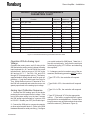
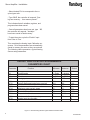
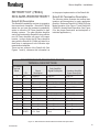
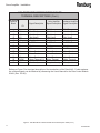
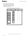
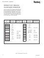
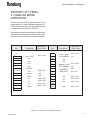
1
SERVICE MANUAL
LN-9405-00.1
Replaces (LN-9405-00)
SERVO AMPLIFIER
MODEL: 22-1589
IMPORTANT: Before using this equipment, carefully read
SAFETY PRECAUTIONS, starting on page 1, and all
instructions in this manual. Keep this Service Manual for
future reference.
Service Manual Price: $20.00
LN-9405-00.1
Servo Amplifier - Contents
CONTENTS
SAFETY:
PAGE
1-3
SAFETY PRECAUTIONS.......................................................................................................... 1
HAZARDS / SAFEGUARDS...................................................................................................... 2-3
INTRODUCTION:
4-5
GENERAL DESCRIPTION.........................................................................................................
SERIAL AND NETWORK COMMUNICATION PORTS...........................................................
ESTABLISH COMMUNICATION TO AMPLIFIER.....................................................................
CONNECT AND CONFIGURE AMPLIFIER.............................................................................
DOWNLOADING PROCEDURE...............................................................................................
4
4
4-5
5
5
INSTALLATION:
6-16
SETUP AND OPERATION......................................................................................................... 6
PROGRAM MODES................................................................................................................... 7-9
RETROFIT KIT (78694), RCS AMPLIFIER RETROFIT............................................................ 10-12
RETROFIT KIT (78694-02), PULSE MODE OPERATION....................................................... 13
RETROFIT KIT (78694-01), ANALOG MODE OPERATION.................................................... 14
GE FANUC S2K AMPLIFIER TERMINATION........................................................................... 15-16
TROUBLESHOOTING GUIDE
17
FRONT PANEL LED DIAGNOSTIC.......................................................................................... 17
PARTS IDENTIFICATION:
18
ORDERING PROCEDURE........................................................................................................ 18
PART NUMBERS........................................................................................................................ 18
WARRANTY POLICIES:
19
LIMITED WARRANTY................................................................................................................ 19
APPENDIX:
20-23
PAINT AND SOLVENT SPECIFICATIONS.............................................................................. 20
VISCOSITY CONVERSION CHART......................................................................................... 21-22
VOLUMETRIC CONTENT OF HOSE OR TUBE...................................................................... 23
LN-9405-00.1
Servo Amplifier - Safety
SAFETY
SAFETY PRECAUTIONS
Before operating, maintaining or servicing any
Ransburg electrostatic coating system, read and
understand all of the technical and safety literature for your Ransburg products. This manual
contains information that is important for you to
know and understand. This information relates to
USER SAFETY and PREVENTING EQUIPMENT
PROBLEMS. To help you recognize this information, we use the following symbols. Please pay
particular attention to these sections.
A WARNING! states information to alert you to a
situation that might cause serious injury if instructions are not followed.
A CAUTION! states information that tells how to
prevent damage to equipment or how to avoid a
situation that might cause minor injury.
A NOTE is information relevant to the procedure
in progress.
While this manual lists standard specifications
and service procedures, some minor deviations
may be found between this literature and your
equipment. Differences in local codes and plant
requirements, material delivery requirements,
etc., make such variations inevitable. Compare
this manual with your system installation drawings
and appropriate Ransburg equipment
manuals to reconcile such differences.
WARNING
> The user MUST read and be familiar with
the Safety Section in this manual and the
Ransburg safety literature therein identified.
> This manual MUST be read and thoroughly understood by ALL personnel who
operate, clean or maintain this equipment!
Special care should be taken to ensure that
the WARNINGS and safety requirements
for operating and servicing the equipment
are followed. The user should be aware of
and adhere to ALL local building and fire
codes and ordinances as well as NFPA 33
SAFETY STANDARD, 1995 EDITION, prior
to installing, operating, and/or servicing this
equipment.
!W A R N I N G
> The hazards shown on the following
page may occur during the normal use of
this equipment. Please read the hazard
chart beginning on page 2.W A
Careful study and continued use of this manual
will provide a better understanding of the equipment and process, resulting in more efficient
operation, longer trouble-free service and faster,
easier troubleshooting. If you do not have the
manuals and safety literature for your Ransburg
system, contact your local Ransburg representative or Ransburg.
1
LN-9405-00.1
Servo Amplifier - Safety
AREA
HAZARD
Tells where hazards Tells what the hazard is.
may occur.
SAFEGUARDS
Tells how to avoid the hazard.
Spray Area
Fire extinguishing equipment must be present
in the spray area and tested periodically.
Fire Hazard
Improper or inadequate opera-tioning and maintenance Spray areas must be kept clean to prevent the
procedures will cause a fire accumulation of combustible residues.
hazard.
Smoking must never be allowed in the spray
Protection against inadvertent area.
arcing that is capable of causing fire or explosion is lost if The high voltage supplied to the atomizer
any safety interlocks are dis- must be turned off prior to cleaning, flushing or
abled during operation. Fre- maintenance.
quent power supply shutdown
indicates a problem in the When using solvents for cleaning:
system requiring correction.
Those used for equipment flushing should have
flash points equal to or higher than those of the
coating material.
Those used for general cleaning must have
flash points above 100°F (37.8°C).
Spray booth ventilation must be kept at the rates
required by NFPA 33, 2000 Edition, OSHA and
local codes. In addition, ventilation must be
maintained during cleaning operations using
flammable or combustible solvents.
Electrostatic arcing must be prevented.
Test only in areas free of combustible material.
Testing may require high voltage to be on, but
only as instructed.
Non-factory replacement parts or unauthorized equipment modifications may cause fire
or injury.
If used, the key switch by-pass is intended for
use only during set-up operations. Production
should never be done with safety interlocks
disabled.
Never use equipment intended for use in waterborne installations to spray solvent based
materials.
LN-9405-00.1
2
Servo Amplifier - Safety
AREA
HAZARD
SAFEGUARDS
Tells where hazards
Tells what the hazard is.
Tells how to avoid the hazard.
Improper operation or maintenance may create a hazard.
Personnel must be given training in accordance
with the requirements of NFPA-33, Chapter 16,
1995 edition.
may occur.
General Use and
Maintenance
Personnel must be properly
trained in the use of this equipment.
Instructions and safety precautions must be read
and understood prior to using this equipment.
Comply with appropriate local, state, and national
codes governing ventilation, fire protection, operation maintenance, and housekeeping. OSHA
references are Sections 1910.94 and 1910.107.
Also refer to NFPA-33, 1995 edition and your
insurance company requirements.
Electrical
Equipment
High voltage equipment is
utilized. Arcing in areas of flammable or combustible materials may occur. Personnel are
exposed to high voltage during
operation and maintenance.
The power supply, optional remote control cabinet,
and all other electrical equipment must be located
outside Class I or II, Division 1 and 2 hazardous
areas. Refer to NFPA No. 33, 1995 Edition.
Turn the power supply OFF before working on the
equipment.
Protection against inadvertent
arcing that may cause a fire or
Test only in areas free of flammable or combusexplosion is lost if safety circuits tible material.
are disabled during operation.
Testing may require high voltage to be on, but
Frequent power supply shutonly as instructed.
down indicates a problem in the
system which requires correcProduction should never be done with the safety
tion.
circuits disabled.
An electrical arc can ignite coat- Before turning the high voltage on, make sure no
ing materials and cause a fire or objects are within the sparking distance.
explosion.
3
LN-9405-00.1
Servo Amplifier - Introduction
INTRODUCTION
(For a General Description, Features, and
Specifications, Reference GE Fanuc S2K
Series Standalone Motion Controller User’s
Manual, GFK-1848)
SERIAL AND NETWORK
COMMUNICATION PORTS
Summary of DIP Switch Functions
Refer to the S2K Hardware Manual for an explanation of the DIP Switch functions. Set the DIP
Switches for Device Net Address and baud rate
if used.
Serial Port
The S2K includes a serial port that is used to set
the operational parameters. The serial port is an
RS-232 port designed to operate a 7 data bits, 1
stop bit, and odd parity.
A typical 2 conductor shielded cable can be used
to communicate to the S2K amplifier. The connectors are the standard 9-pin D-Sub connector
style. The wiring is a straight through style where
the shield is connected to pin 5 of both D-Sub
connectors. The red wire is connected to pin 3
and the black wire is connected to pin 2 of both
connector ends. Refer to the Hardware Manual
(GE Fanuc, S2K Series Manual) for additional
wiring information.
Cable Length Maximum
Communication cables exceeding 30 meters
in length must be enclosed in grounded metal
conduit.
ESTABLISH
COMMUNICATION TO
AMPLIFIER
(For a General Description of programing
protocol, reference GE Fanuc Generation D
Real-Time Operating System Program-ing
Manual, GFK-2205.)
Cable Connection
Connect the serial cable to the serial port on the
S2K amplifier and tighten screws to fasten the
connector. Connect the opposite end of serial
cable into the RS-232 serial communication port
of computer. Tighten the screws to fasten the
connector.
Install Operating Software
The operating software for this amplifier is proprietary of GE Fanuc. The operating software is
titled “CCS Win32.” Insert CCS Win32 CD into
computer and install. Follow typical Window installation methods.
Communicating to Amplifier
1. Open CCS
2. From Terminal window, select
Options/Communication Setup
3. Select Serial Communication
4. Select the appropriate COM Port setting
5. Leave Baud Rate set to its default value of 9600
6. Click OK
7. Select Options/Controller Settings
8. Select Serial as the Communication Type
9. Select S2K as the Controller Type
10. Click OK
11. Press enter and the S2K will sign on.
LN-9405-00.1
4
Servo Amplifier - Introduction
CONNECT AND
CONFIGURE AMPLIFIER
Amplifier Termination
• Complete the motor, power, and I/O wiring to
the S2K Amplifier. (Reference system prints and
GE Fanuc Manual.)
• Maximum encoder cable length is 15 meters
using factory supplied cables.
• Maximum resolver cable length is 50 meters
using factory supplied cables.
• Positive feedback cables exceeding 30 meters
in length must be enclosed in grounded metal conduit.
• Reference system drawings for specific application terminations.
• Operation with a Pulse Source or Operation
with an Analog Input voltage can also be used
for reference.
• Jumper ENABLE to Common if using internal
12- volt supply or to your external supply common.
Jumper ENABLE + to + voltage if using internal
+12 Volt supply or to your external supply + voltage. (Reference the system drawings as this
Enable signal may already be terminated.)
Enable the Drive
Close the Enable switch from your external device to clear the fault condition. The digital status
LED on the front of the S2K will change to OK.
By toggling this Enable bit, it will allow the operator to clear faults and enter programs during the
programming mode.
5
DOWNLOADING
PROCEDURE
Summary of Downloading Procedure
(Refer to the GE Fanuc Generation D Real-Time
Operating System Programing Manual, GFK-2205
for further explanation.)
• Type STF (Set Fault, faults program)
• Type KLALL (Kill All, halts programs which
enables programs to be up or down loaded.)
• Type UPS=O (UPS must be set to its default
value of zero before CLM command will func-
tion.)
• Type CLM (Clear Memory) Are your sure you
want to clear all the user memory and reset the
registers to their default valves?
• Type Y (Yes) (User memory cleared.)
• Click Tools/Send Files
• Select program to download
• Do you wish to save Programs and Motion
Blocks? Click on Yes
• Type Yes (Then the screen will tell you that
the user memory has been saved.)
• Click OK or OPEN
Program is in the form of a text file and will be
downloaded to the Amplifier.
LN-9405-00.1
Servo Amplifier - Installation
INSTALLATION
SETUP AND OPERATION
Summary of Dip Switch Functions
To Q u e r y a p a r a m e t e r, t y p e ( a d d r )
variable?<Enter>where<Enter>is the Enter key
on your terminal.
(Refer to the S2K Hardware Manual for an explanation of the DIP Switch functions. Reference the
system prints for the correct settings.)
For example: 1VI1?<Enter>will report the mode:
0=pulse input, 1=analog input.
Software Programmable Parameters
For example: 1PLA=512<Enter>sets the gear
ratio to 1:1.
The SMD emulator program in the S2K allows
all of the original SMD parameters to be set in
software in the S2K. Following is a list of the parameters. These parameters must be set with the
power ON, but with the Enable input set to OFF.
To set a parameter, type (addr) variable = <Enter>
where<Enter>is the Enter key on your terminal.
DEFAULT PROGRAMMABLE PARAMETERS
Parameter
PLA
VI1
VI4
VF10
VF11
VF12
VF13
VF14
VF15
VF16
VF18
VF19
Function
Sets gear ratio
Control mode
Direction
Analog input zero
Analog input full scale
Output shaft speed scale factor, rpm/volt
Accel time constant, milleseconds
Maximum motor current, amps
Control stiffness, %
Torque to Inertia ratio
Maximum shaft output speed, rpm
Analog input time constant
Minimum
Maximum
512 = 1:1
0 = Pulse
0 = CW
-10.0
+2.0
10.0
2
0.5
25
330
10
5120 = 1:1
1 = Analog
1 = CCW
+10.0
+10.0
25.0
100
3.0
200
60000
255
Default
512
1
0
0.0
+10.0
15.0
22
3.0
100
3000
150
4
The above parameters are the factory default setting and any modifications must be programmed.
Proceed to Program Modes.
Figure 2: Default Programmable Parameters Table
LN-9405-00.1
6
Servo Amplifier - Installation
PROGRAM MODES
Operation With A Pulse Source
Complete a motor, power, and I/O wiring to the
terminal block. When wiring for pulse and direction, Channel A is the pulse input and Channel B
is the direction input. Apply a soure of 115 VAC to
the IMJ. Connect the S2K serial port to a personal
computer or other serial terminal device. Refer
to the S2K Hardware Manual for serial port wiring and Serial Port. (Refer to Page 4) Configure
your serial terminal for 9600 baud, 7 data bits, 1
stop bit, and odd parity. Verify that the serial port
is working by typing 1FC?<Enter> and observe
the response. Then proceed with the following:
• Type STF<CR>, the controller will respond
“*”.
• Type KLALL<CR>, the controller will respond
“*”.
• Type VI1=0<CR>, the controller will respond
“*”.
The S2K will rotate the motor in synchronism with
the input pulse source. In this mode, the motor
displacement is proportional to the number of
pulses received, and motor speed is proportional
to the frequency of the pulse train.
The following table represents typical Pulse
Source setup parameters. However, depending
on the vintage of the system that this amplifier
is being retrofitted to, the following parameters
could be different:
• VI1 should be setup to a value of 0, (VI1 tells
the amplifer how to function, in either pulse mode
or analog mode).
• VI4 should be set to 0, but a verification of
direction may be required and a setting of 1 may
be required in some applications (VI4 tells the
amplifier what direction the motor is to be running).
• VF18 should be set for 150, but an older vinage system may require a setup of 120 (VF18
tells the amplifier what the maximum shaft output
speed is to be).
• Type VF10 through VF18 to the appropriate
values. (The factory supplied default values
should work for most applications. Contact Ransburg if there are any questions about what values
should be entered.) (Refer to Figure 3)
• Select desired PLA to correspond to the required gear ratio.
• Type SAVE, the controller will respond, “Saving user memory... User memory saved.”
• Once all parameters have been set, type EXP1,
the controller will respond, “Variables have been
saved to flash memory.”
This indicates that all variables, registers, and
programs have been saved. To start the motor,
cycle the “Enable” input from false to true.
• Toggle the “Enable” signal.
7
LN-9405-00.1
Servo Amplifier - Installation
DEFAULT PULSE MODE PROGRAMMABLE
PARAMETERS CHART
Parameter
PLA
VI1
VI4
VF10
VF11
VF12
VF13
VF14
VF15
VF16
VF18
VF19
Function
Minimum
Sets gear ratio
Control mode
Direction
Analog input zero
Analog input full scale
Output shaft speed scale factor, rpm/volt
Accel time constant, milleseconds
Maximum motor current, amps
Control stiffness, %
Torque to Inertia ratio
Maximum shaft output speed, rpm
Analog input time constant
512 = 1:1
0 = Pulse
0 = CW
-10.0
+2.0
10.0
2
0.5
25
330
10
Maximum
5120 = 10:1
1 = Analog
1 = CCW
+10.0
+10.0
25.0
100
3.0
200
60000
255
Default
512
0
0
+0.0
+10.0
15.0
22
3.0
100
3000
150/120
4
Figure 3: Default Pulse Mode Programmable Parameters Table
Operation With An Analog Input
Voltage
Complete the motor, power, and I/O wiring to the
S2K and wire the analog control voltage to analog
input terminals AI+, AI-, and ACOM on the screw
terminal block. Apply a source of 115 VAC to the
IMJ and set VI1 = 1. Set PLA, VI4, and VF10
through VF18 to appropriate values. (The factory
supplied default values should work for most applications.) Cycle the Enable input from False to
True. When the Run Input on I/O terminal is True,
the S2K will accelerate and rotate the motor at a
speed proportional to the analog input voltage.
Analog Input Calibration Sequence
1. Connect the S2K analog input to the device
producing the motor speed control voltage. If the
rest of the system wiring is not in place, connect
the S2K power input terminals to a source of 90
to 130 VAC. Disable (turn OFF) the Enable input.
2. Connect the S2K port to a personal computer
or other serial terminal device. (Refer to the S2K
Hardware Manual for serial port wiring.) Configure
LN-9405-00.1
your serial terminal for 9600 baud, 7 data bits, 1
stop bit, and odd parity. Verify that the serial port
is working by typing 1FC?<Enter> and observing
the response.
3. If changes need to be made to any of the parameters, the following procedure MUST be done:
• Type STF<CR>, the controller will respond
“*”.
• Type KLALL<CR>, the controller will respond
“*”.
• Type VI1=1<CR>, the controller with respond
“*”.
! Type VF10 through VF18 to the appropriate
values. (The factory supplied default values
should work for most applications. Contact Ransburg if there are any questions about what values
should be entered.) (Reference Figure 4)
8
Servo Amplifier - Installation
• Select desired PLA to correspond to the required gear ratio.
• Type SAVE, the controller wil respond, “Saving user memory... User memory saved.”
This indicates that all variables, registers, and
programs have been saved.
• Once all parameters have been set, type XP1,
the controller will respond, “Variables
have been saved to flash memory.”
• To start the motor, cycle the “Enable” input
from False to True.
This completes the Analog Input Calibration sequence. All of the parameters are automatically
saved to memory as soon as they are entered.
The following table represents a typical Analog
Source setup parameters.
DEFAULT ANALOG MODE PROGRAMMABLE
PARAMETERS CHART
Parameter
PLA
VI1
VI4
VF10
VF11
VF12
VF13
VF14
VF15
VF16
VF18
VF19
Function
Sets gear ratio
Control mode
Direction
Analog input zero
Analog input full scale
Output shaft speed scale factor, rpm/volt
Accel time constant, milleseconds
Maximum motor current, amps
Control stiffness, %
Torque to Inertia ratio
Maximum shaft output speed, rpm
Analog input time constant
Minimum
512 = 1:1
0 = Pulse
0 = CW
-10.0
+2.0
10.0
2
0.5
25
330
10
Maximum
5120 = 10:1
1 = Analog
1 = CCW
+10.0
+10.0
25.0
100
3.0
200
60000
255
Default
512
1
0
0
+10.0
15.0
22
3.0
100
3000
150
4
Figure 4: Default Analog Mode Programmable Parameters Table
9
LN-9405-00.1
Servo Amplifier - Installation
RETROFIT KIT (78694),
RCS AMPLIFIER RETROFIT
Retrofit Kit Description
This Retrofit Kit enables the end user to upgrade to
the current level of amplifier. Retrofit Kit (78694)
allows the end user the backward compatibility
option to utilize the GE Fanuc Amplifier in their
existing systems. The older Whedco Amplifier
can be removed and this Retrofit Kit along with the
new GE Fanuc Amplifier will mount in the same
location. In other words, the GE Fanuc Amplifier
along with the Retrofit Kit (78694) will allow for a
direct drop in replacement to the Whedco style
manufactured amplifier.
There are two versions of the Retrofit Kit (See
Figures 7 and 8), reference this information as
to the proper implementation of the Retrofit Kit.
Retrofit Kit Termination Description
The following tables illustrate the terminal designations and descriptions for each application
possible. Reference Retrofit Kit (78694-02) Pulse
Mode Operation (See Figure 7) and Retrofit Kit
(78694-01) Analog Mode Operation (See Figure
8 for the proper termination and description of
individual applications.)
S2K RETROFIT KIT TRANSITION BOARD
TERMINAL DESCRIPTIONS
S2K Retrofit
Terminal
Block
1
2
3
4
5
6
7
8
9
10
11
12
13
Signal
Description
I.D.
Al+
ACOM
N.C.
ABGND
ENOKN.C.
R2
S3
S4
GND/
SHLD
Analog +
DC Common
(Not Used)
Channel AChannel BDC Common
Enable OK (Not Used)
Motor Resolver
Motor Resolver
Motor Resolver
Motor Thermal
O.L. Gnd.
Color Amplifier
Signal Description
DAC A+
DC Common
(Not Used)
Freq. Out from MCM
MON/OFF A+
DC Common
Enable CLR AMP FAULT
(Not Used)
Motor Resolver
Motor Resolver
Motor Resolver
Motor Thermal O.L.
Gnd.
Hardener Amplifier
Signal Description
DAC B+
DC Common
(Not Used)
Freq. Out from MCM
MON/OFF B+
DC Common
Enable HD AMP Fault
(Not Used)
Motor Resolver
Motor Resolver
Motor Resolver
Motor Thermal O.L.
Gnd.
Figure 5: S2K Retrofit Kit Transition Board Terminal Description Table
LN-9405-00.1
10
Servo Amplifier - Installation
S2K RETROFIT KIT TRANSITION BOARD
TERMINAL DESCRIPTIONS (Cont.)
S2K Retrofit
Terminal
Block
14
15
16
17
18
19
20
21
22
23
24
25
26
I.D.
AlN.C.
N.C.
N.C.
N.C.
PULS OUT
EN+
OK+
R1
S1
S2
THRM
N.C.
Signal Description
Color Amplifier
Hardener Amplifier
Signal Description Signal Description
Analog(Not Used)
(Not Used)
(Not Used)
(Not Used)
N.FREQ.
Enable +
OK +
Motor Resolver
Motor Resolver
Motor Resolver
Motor Thermal O.L.
(Not Used)
DAC A(Not Used)
(Not Used)
(Not Used)
(Not Used)
N. FREQ.A
Enable +
24 VDC
Motor Resolver
Motor Resolver
Motor Resolver
Motor Thermal
O.L. (Not Used)
DAC B(Not Used)
(Not Used)
(Not Used)
(Not Used)
N.FREQ.B
Enable +
24VDC
Motor Resolver
Motor Resolver
Motor Resolver
Motor Thermal
O.L. (Not Used)
Reference Figure 5 for the signal description of the terminations of the Retrofit Kit. Further explanation of these signals can be obtained by referencing the User’s Manual for the Raio Control Module
22-461 (Doc. 122-63).
Figure 5: S2K Retrofit Kit Transition Board Terminal Description Table (Cont.)
11
LN-9405-00.1
Servo Amplifier - Installation
Reference the S2K Retrofit Kit Transition Board
Terminal Description for the signal description
of the terminations of the Retrofit Kit. Further
explanation of these signals can be obtained by
referencing the User’s Manual for the Ratio Control Module 22-461 (Doc. 122-63).
S2K Retrofit Kit Transition Board Terminals
TB1
TB2
1
D - Sub
Connector
Al+
13
1
Al-
ACOM
14
2
N.C.
N.C.
15
3
N.C.
A-
16
4
N.C.
B-
17
5
N.C.
GND
18
6
PLS OUT
EN-
19
7
EN+
OK-
20
8
OK+
N.C.
21
9
R1
R2
22
10
S1
S3
23
11
S2
S4
24
12
GND
25
14
/
THRM
SHLD
N.C
26
13
Figure 6: S2K Retrofit Kit Transition Board Terminals (78653) Table
LN-9405-00.1
12
Servo Amplifier - Installation
RETROFIT KIT (78694-02)
PULSE MODE OPERATION
This kit is used in RCS Systems that utilize the
Motor Control Modules (MCM 22-556). Reference
the following table for information on how to terminate the Retrofit Kit (78694-02). Wire numbers
have been denoted to illustrate the typical wire
numbering used. Reference the system prints
for the correct wire number donotation.
TB1
Description
Typical Wire #
Color / Hard
14
AlN.C.
N.C.
N.C.
N.C.
PLS OUT
EN+
OK+
R1
S1
S2
THRM
N.C
26
TB2
Description
Typical Wire #
Color / Hard
1
N.U
Al+
N.U
N.U.
ACOM
N.U.
N.U.
N.C.
N.U.
N.U.
A-
N.U.
B-
N.FREQ.
A/B
24 VDC
24 VDC
R1
S1
S2
THRM
CHANL A-
4021 / 4070
1071
GND
4028 / 4089
DC COMMON
EN-
1260
AMP RESET
OK-
1260
AMP FAULT
N.C.
4030 / 4091
R2
4032 / 4093
R2
S3
4034 / 4095
S3
S4
4035 / 4096
4051 / 4111
S4
GND/
GND
4052 / 4112
SHLD
4143
X22 / X23
4031 / 4092
4033 / 4094
13
Figure 7: S2K Retrofit Kit - Pulse Mode
13
LN-9405-00.1
Servo Amplifier - Installation
RETROFIT KIT (7869401) ANALOG MODE
OPERATION
This kit is used in RCS Systems that use the UL
Listed and non-UL Listed Whedco Amplifiers (221589). Reference Figure 8 for information on how
to terminate the Retrofit Kit (78694-01).
Wire numbers have been denoted to illustrate the
typical wire numbering used. Reference the System prints for the correct wire number denotation.
TB1
Description
Typical Wire #
Color / Hard
N.C.
N.C.
N.C.
N.C.
PLS OUT
EN+
OK+
R1
S1
S2
THRM
N.C
26
Description
Typical Wire #
Color / Hard
DAC + (A/B)
4020 / 4110
1
14
Al-
TB2
DAC - (A/B)
4011 / 4101
Al+
ACOM
DC COMMON
N.U
N.C.
N.U.
N.U.
A-
N.U.
N.U.
B-
MON/OFF (A/B)
N.U.
GND
DC COMMON
N.FREQ.
EN-
AMP RESET
OK-
AMP FAULT
A/B
24 VDC
24 VDC
R1
4028 / 4128
1260
1260
4030 / 4130
4032 / 4132
S1
4034 / 4134
S2
THRM
4051 / 4151
1071
4010 / 4100
1071
4080
X22 / X23
N.C.
4031 / 4131
R2
R2
S3
S3
S4
S4
4035 / 4135
GND
4052 / 4152
4033 / 4133
GND/
SHLD
13
Figure 8: S2K Retrofit Kit - Analog Mode Operation
LN-9405-00.1
14
Servo Amplifier - Installation
GE FANUC S2K AMPLIFIER
TERMINATION
S2K Auxilary I/O Cable Description
The following Tables depict the terminations used
for the GE Fanuc S2K Style amplifiers. These
show the wiring of post June 2002 systems, where
a Retrofit Kit was not required. (Reference documentation Schematic, RCS, 22-1035 (77809),
sheet 4 of 8.) (Reference the system prints for
the correct wire number denotation.)
This table can be referenced against Ransburg
RCS Amplifier Cable (78615) for additional clarification.
S2K RETROFIT KIT TRANSITION BOARD
TERMINAL DESCRIPTIONS
S2K
Ausiliary
I/O Cable
1
2
5
6
7
8
14
19
20
21
I.D.
Al+
Color
Amplifier
Signal
Number
Signal
Description
Color
Amplifier
Signal
Description
Analog +
DC Common
Channel BDC Common
Enable OK Analog N. FREQ.
DAC A+
DC Common
MON/OFF A+
DC Common
Enable CLR AMP FAULT
(DAC AN.FREQ. A
4020
1071
4010
1071
4080
X22
4011
4028
DAC B+
DC Common
MON/OFF B+
DC Common
Enable HD AMP Fault
DAC BN.FREQ. B
4110
1071
4100
1071
4080
X23
4101
4128
Enable +
OK +
Enable +
24 VDC
1260
1260
Enable +
24 VDC
1260
1260
Hardener
Amplifier Signal
Description
Hardner
Amplifier
Signal
Number
Figure 9: S2K Auxiliary I/O Cable Table
15
LN-9405-00.1
Servo Amplifier - Installation
S2K POSITION FEEDBACK CABLE
S2K
Ausiliary
I/O Cable
I.D.
Signal
Description
1
2
3
4
5
6
R1
R2
S1
S3
S2
S4
Mtr. Resolver
Mtr. Resolver
Mtr. Resolver
Mtr. Resolver
Mtr. Resolver
Mtr. Resolver
7
8
Thrm
GND/
SHLD
SHLD
SHLD
SHLD
SHLD
SHLD
SHLD
SHLD
9
10
11
12
13
14
15
Color
Amplifier
Signal
Description
Color
Amplifier
Wire
Number
Hardener
Amplifier
Signal
Description
Hardener
Amplifier
Wire
Number
4030
4031
4032
4033
4034
4035
Mtr. Resolver
Mtr. Resolver
Mtr. Resolver
Mtr. Resolver
Mtr. Resolver
Mtr. Resolver
4130
4131
4132
4133
4134
4135
Mtr. Thrm. OL
MTR. Thrm. OL
Mtr. Resolver
Mtr. Resolver
Mtr. Resolver
Mtr. Resolver
Mtr. Resolver
Mtr. Resolver
Mtr. Thrm. OL
MTR. Thrm. OL
4051
4052
Mtr. Thrm. OL
MTR. Thrm. OL
4151
4152
SHLD
SHLD
SHLD
SHLD
SHLD
SHLD
SHLD
SHLD
SHLD
SHLD
SHLD
SHLD
SHLD
SHLD
SHLD
SHLD
SHLD
SHLD
SHLD
SHLD
SHLD
SHLD
SHLD
SHLD
SHLD
SHLD
SHLD
SHLD
SHLD
SHLD
SHLD
SHLD
SHLD
SHLD
SHLD
Figure 10: S2K Position Feedback Cable Table
S2K MOTOR WINDING AND LINE
POWER TERMINATIONS
S2K
Contacts
GND
T
S
R
GND
L3
L2
L1
Color
Amplifier
Signal
Description
Color
Amplifier
Wire
Number
GND
Mtr. Winding
Mtr. Winding
Mtr. Winding
GND
120 VAC
120 VAC
(Not Used)
GND
4063
4062
4061
GND
2
1080
(Not Used)
Hardener
Amplifier
Signal
Description
GND
Mtr. Winding
Mtr. Winding
Mtr. Winding
GND
120 VAC
120 VAC
(Not Used)
Hardener
Amplifier
Wire
Number
GND
4163
4162
4161
GND
2
1100
(Not Used)
Figure 11: S2K Motor Winding and Line Power Terminations Table
LN-9405-00.1
16
Servo Amplifier - Troubleshooting Guide
TROUBLESHOOTING GUIDE
FRONT PANEL LED
DIAGNOSTICS
The front panel LED on S2K controllers reports
real-time diagnostic as shown in Figure 12.
LED DIAGNOSTIC FAULTS
Mnemonic
OK
CC
DT
EC
EI
FE
FL
LE
MT
OC
OV
PF
PO
SF
UV
00-63
•
Controller
Status
OK
Faulted
Faulted
Faulted
Faulted
Faulted
Faulted
Faulted
Faulted
Faulted
Faulted
Faulted
Faulted
Faulted
Faulted
OK / Faulted
OK / Faulted
Description
Drive enabled CPU’s and operating system functional
Motor power clamp over current
Drive over temperature
Motor power clamp excessive duty cycle
Excessive command increment
Excess following error
Feedback lost (Servo)
Lost enable
Motor over temperature (Servo only)
Motor over current
Motor power over voltage
Power failure
Position register overflow
Software fault
Motor power under voltage
DeviceNet node address
Flashing decimal indicates serial communication is occurring.
Fault and status registers are also available to report faults for the system, input, general I/O, axis status, program
status, and system status. Those register messages, their causes, and their possible solutions are documented
in GE Fanuc manuals, GFK-2205 and GFK-1848.
Figure 12: Diagnostic Faults Table
17
LN-9405-00.1
Servo Amplifier - Parts Identification
PARTS IDENTIFICATION
SERVO AMPLIFIER PART NUMBERS
PART #
DESCRIPTION
22-1589
Amplifier
78694-00
Retrofit Kit
78694-01
Analog Mode - Includes 78652-00 (cable assembly), 78651-00
(mounting plate), and 78653-00 (transition board)
78694-02
Pulse Mode - Includes 78693-00 (cable assembly), 78651-00 (mounting plate), and 78653-00 (transition board)
LN-9405-00.1
18
Servo Amplifier - Warranty Policies
WARRANTY POLICIES
LIMITED WARRANTY
Ransburg will replace or repair without charge any
part and/or equipment that falls within the specified
time (see below) because of faulty workmanship
or material, provided that the equipment has been
used and maintained in accordance with Ransburg’s written safety and operating instructions,
and has been used under normal operating conditions. Normal wear items are excluded.
THE USE OF OTHER THAN RANSBURG APPROVED PARTS, VOIDS ALL WARRANTIES.
SPARE PARTS: One hundred and eighty (180)
days from date of purchase, except for rebuilt
parts (any part number ending in “R”) for which
the warranty period is ninety (90) days.
EQUIPMENT: When purchased as a complete unit,
(i.e., guns, power supplies, control units, etc.), is
one (1) year from date of purchase. WRAPPING
THE APPLICATOR IN PLASTIC, SHRINK-WRAP,
ETC., WILL VOID THIS WARRANTY.
WARRANTY IS TO REPLACE PARTS THAT
HAVE FAILED BECAUSE OF FAULTY WORKMANSHIP OR MATERIALS. THERE ARE NO
IMPLIED WARRANTIES NOR WARRANTIES OF
EITHER MERCHANTABILITY OR FITNESS FOR
A PARTICULAR PURPOSE. AUTOMOTIVE ASSUMES NO LIABILITY FOR INJURY, DAMAGE
TO PROPERTY OR FOR CONSEQUENTIAL
DAMAGES FOR LOSS OF GOODWILL OR
PRODUCTION OR INCOME, WHICH RESULT
FROM USE OR MISUSE OF THE EQUIPMENT
BY PURCHASER OR OTHERS.
EXCLUSIONS:
If, in Ransburg’s opinion the warranty item in
question, or other items damaged by this part
was improperly installed, operated or maintained,
Ransburg will assume no responsibility for repair or
replacement of the item or items. The purchaser,
therefore will assume all responsibility for any
cost of repair or replacement and service related
costs if applicable.
FLUID HANDLING: One (1) year from date of
purchase (i.e., Totalizer, CCV Valves, etc.).
AIR BEARING ROTATORS: Fifteen thousand
(15,000) hours or three (3) years, whichever occurs first. Warranty period begins on the date of
purchase.
RANSBURG’S ONLY OBLIGATION UNDER THIS
19
LN-9405-00.1
Servo Amplifier - Appendix
APPENDIX
PAINT AND SOLVENT SPECIFICATIONS
RECOMMENDED VISCOSITY USING A ZAHN NO. 2
PAINT ELECTRICAL RESISTANCE**
RECOMMENDED DELIVERY (UP TO)
REATM / EFMTM
EVOLVER
18 TO 30 SEC
.1 MΩ TO ∞
1000 cc/min
REMTM / M90TM
18 TO 30 SEC
.1 MΩ TO ∞
1500 cc/min
NO. 2 HAND GUN
20 TO 60 SEC
.1 TO 1 MΩ
180 cc/min
TURBODISKTM
20 TO 60 SEC
.1 MΩ TO ∞
1000 cc/min
AEROBELL® II***
AEROBELL®
AEROBELL® 33
RMATM-101
20 TO 60 SEC
.1 MΩ TO ∞
500 cc/min
GUIDE TO USABLE SOLVENT SELECTION
Chemical
Name
DICHLOROMETHANE
VM & P NAPHTHA
ACETONE
METHYL ACETATE
BENZENE
ETHYL ACETATE
2-BUTANONE
ISO-PROPYL ACETATE
ISOPROPYL ALCOHOL
2-PENTANONE
METHANOL
PROPYL ACETATE
TOLUOL
METHYL ISOBUTYL KETONE
ISOBUTYL ACETATE
ETHANOL
BUTYL ACETATE
ETHYLBENZENE
1-PROPANOL
2-BUTANOL
XYLOL
AMYL ACETATE
2-METHYLPROPANOL
METHYL AMYL ACETATE
5-METHYL-2-HEXANONE
1-BUTANOL
2-ETHOXYETHANOL
2-HEPTANONE
CYCLOHEXANONE
AROMATIC-100
DIISOBUTYL KETONE
1-PENTANOL
DIACETONE ALCOHOL
2-BUTOXYETHANOL
CYCLOHEXANOL
AROMATIC-150
AROMATIC-200
Common
Name
Category
Methylene Chloride Chlorinated Solvents
Naptha
Aliphatic Hydrocarbons
Ketones
Esters
Aromatic Hydrocarbons
Esters
MEK
Ketones
Esters
IPA
Alcohols
MPK
Ketones
Methyl Alcohol
Alcohols
n-Propyl Acetate
Esters
Toluene
Aromatic Hydrocarbons
MIBK
Ketones
Esters
Ethyl Alcohol
Alcohols
Esters
Aromatic Hydrocarbons
n-Propyl Alcohol
Alcohols
sec.-Butyl Alcohol
Alcohols
Xylene
Aromatic Hydrocarbons
Esters
iso-Butyl Alcohol
Alcohols
Esters
MIAK
Ketones
n-Butyl Alcohol
Alcohols
Glycol Ethers
MAK
Ketones
Ketones
SC#100
Aromatic Hydrocarbons
DIBK
Ketones
Amyl Alcohol
Alcohols
Ketones
Butyl Cellosolve
Glycol Ethers
Alcohols
SC#150
Aromatic Hydrocarbons
Aromatic Hydrocarbons
Flash Point††
(TCC)
65oF
-18oF
90oF
12oF
24oF
16oF
35oF
53oF
104oF
50oF
55oF
48oF
60oF
69oF
78oF
64oF
74oF
72oF
79oF
106oF
82oF
96oF
96oF
95oF
164oF
102oF
111oF
111oF
120oF
133oF
154oF
111oF
149oF
203oF
*CAS
Number
75-09-2
8030-30-6
67-64-1
79-20-9
71-43-2
141-78-6
78-93-3
108-21-4
67-63-0
107-87-9
67-56-1
109-60-4
108-88-3
108-10-1
110-19-0
64-17-5
123-86-4
100-41-4
71-23-8
78-92-2
1330-02-07
628-63-7
78-83-1
108-84-9
110-12-3
71-36-3
110-80-5
110-43-0
108-94-1
108-83-8
71-41-0
123-42-2
111-76-2
108-93-0
Evap.
Rate†
14.5
10
5.6
5.3
5.1
3.9
3.8
3.4
2.5
2.5
2.1
2.1
1.9
1.6
1.5
1.4
1.0
.89
.86
.81
.80
.67
.62
.50
.50
.43
.38
.40
.29
.20
.19
.15
.12
.07
.05
.004
.003
⇑F
A
S
T
E
R
S
L
O
W
E
R
⇓
Elec.
Res.**
HIGH
HIGH
LOW
LOW
HIGH
MEDIUM
MEDIUM
LOW
LOW
MEDIUM
LOW
LOW
HIGH
MEDIUM
LOW
LOW
LOW
HIGH
LOW
LOW
HIGH
MEDIUM
LOW
LOW
MEDIUM
LOW
LOW
MEDIUM
MEDIUM
HIGH
MEDIUM
LOW
LOW
LOW
LOW
HIGH
HIGH
© 2013 Ransburg. All rights reserved.
* CAS Number: Chemical Abstract Service Number.
** Electrical Resistance using the Ransburg Meter.
*** Solvent Base Configuration Only.
†
Information Obtained From: http://solvdb.ncms.org
††
The lowest temperature at which a volatile fluid will ignite.
Evaporation Rate is Based Upon Butyl Acetate Having a Rate of 1.0
NOTE: Chart provides resistance and control information that we feel is necessary when using Ransburg equipment.
LN-9405-00.1
20
Servo Amplifier - Appendix
21
Din Cup 4
Sears
Craftsman Cup
Zahn 5
Zahn 4
Zahn 3
Zahn 2
Zahn 1
Saybolt Universal
SSU
Gardner Lithographic
Krebs Unit
KU
Gardner Holdt Bubble
Ford Cup 4
Ford Cup 3
Fisher 2
Fisher 1
DuPont
Parlin 10
DuPont
Parlin 7
Centipoise
Poise
VISCOSITY CONVERSION CHART
.1
10
27
11
20
5 A-4
60
30
16
.15
15
30
12
25
8 A-3
80
34
17
11
.2
20
32
13
30
15
10
100
37
18
12
.25
25
37
14
35
17
12 A-2
130
41
19
13
.3
30
43
15
39
18
14 A-1
160
44
20
.4
40
50
16
50
21
18
210
52
22
19
15
.5
50
57
17
24
22
260
60
24
20
16
.6
60
64
18
29
25
320
68
27
21
18
.7
70
20
33
28
370
30
23
21
.8
80
22
39
31
430
34
24
23
A
B
C
10
14
.9
90
23
44
32
480
37
26
25
1.0
100
25
50
34
D
530
41
10
27
27
1.2
120
30
62
41
E
580
49
11
31
31
1.4
140
32
45
F
690
58
13
34
34
1.6
160
37
50
G
790
66
14
38
38
1.8
180
41
54
900
74
16
40
43
2.0
200
45
58
H
1000
82
17
44
46
2.2
220
62
I
1100
18
51
2.4
240
65
J
1200
20
55
2.6
260
68
1280
21
58
2.8
280
70
K
1380
22
63
3.0
300
74
L
1475
24
68
3.2
320
M
1530
25
72
3.4
340
N
1630
26
76
3.6
360
O
1730
28
82
3.8
380
1850
29
86
4.0
400
1950
30
90
4.2
420
2050
32
95
4.4
440
Q
2160
33
100
4.6
460
R
2270
34
104
4.8
480
2380
36
109
5.0
500
S
2480
37
112
5.5
550
T
2660
40
124
6.0
600
U
2900
44
135
7.0
700
3375
51
160
8.0
800
3380
58
172
9.0
900
V
4300
64
195
10.0 1000
W
4600
000
P
00
0
11.0 1100
5200
12.0 1200
5620
218
LN-9405-00.1
Servo Amplifier- Appendix
18.0 1800
1
Y
103
9850
22.0 2200
10300
Z
2
24.0 2400
3
Din Cup 4
129 16500
133 18500
Z-3
136 21000
23500
55.0 5500
26000
Z-4
4
2800
65.0 6500
30000
70.0 7000
32500
75.0 7500
35000
80.0 8000
37000
85.0 8500
39500
90.0 9000
41000
95.0 9500
43000
Z-5
5
46500
110.0 11000
51000
120.0 12000
55005
130.0 13000
60000
140.0 14000
150.0 15000
Sears
Craftsman Cup
121 14500
Z-2
50.0 5000
100.0 10000
Zahn 5
114 11600
40.0 4000
60.0 6000
105 10750
109 11200
Z-1
30.0 3000
45.0 4500
Zahn 4
9400
21.0 2100
35.0 3500
Zahn 3
9000
20.0 2000
25.0 2500
64
8500
19.0 1900
23.0 2300
Zahn 2
8000
X
14.0 1400
Zahn 1
Saybolt Universal
SSU
7500
101
Gardner Holdt Bubble
100
17.0 1700
Ford Cup 4
16.0 1600
Ford Cup 3
7000
Fisher 2
98
Fisher 1
15.0 1500
DuPont
Parlin 10
6480
13.0 1300
DuPont
Parlin 7
6100
96
Centipoise
95
Poise
Gardner Lithographic
Krebs Unit
KU
VISCOSITY CONVERSION CHART (Continued)
65000
Z-6
67500
160.0 16000
74000
170.0 17000
83500
180.0 18000
83500
190.0 19000
88000
200.0 20000
93000
300.0 30000
Note: All viscosity comparisons are as accurate as possible with existing information.
Comparisons are made with a material having a specific gravity of 1.0.
© 2013 Ransburg. LN-9405-00.1
All rights reserved. 22
Servo Amplifier - Appendix
VOLUMETRIC CONTENT OF HOSE OR TUBE
(English Units)
I.D. (inches)
cc/ft.
Cross
Section
(in.2)
1/8
2.4
.012
3/16
5.4
.028
1/4
9.7 .049
5/16
15.1
.077
3/8
21.7
.110
1/2
38.6
.196
Length
5ft. (60”)
10ft. (120”) 15ft. (180”) 25ft. (300”)
50ft. (600”)
.003 gal.
.4 fl. oz.
.007 gal.
.9 fl. oz.
.013 gal.
1.6 fl. oz.
.020 gal.
2.5 fl. oz.
.029 gal.
3.7 fl. oz.
.051 gal.
6.5 fl. oz.
.006 gal.
.8 fl. oz.
.014 gal.
1.8 fl. oz.
.025 gal.
3.3 fl. oz.
.040 gal.
5.1 fl. oz.
.057 gal.
7.3 fl. oz.
.102 gal.
13.1 fl. oz.
.032 gal.
4.1 fl. oz.
.072 gal.
9.2 fl. oz.
.127 gal.
16.3 fl. oz.
.199 gal.
25.5 fl. oz.
.287 gal.
36.7 fl. oz.
.510 gal.
65.3 fl. oz.
.010 gal.
1.2 fl. oz.
.022 gal.
2.8 fl. oz.
.038 gal.
4.9 fl. oz.
.060 gal.
7.6 fl. oz.
.086 gal.
11.0 fl. oz.
.153 gal.
19.6 fl. oz.
.016 gal.
2.0 fl. oz.
.036 gal.
4.6 fl. oz.
.064 gal.
8.2 fl. oz.
.100 gal.
12.7 fl. oz.
.143 gal.
18.4 fl. oz.
.255 gal.
32.6 fl. oz.
VOLUMETRIC CONTENT OF HOSE OR TUBE
(Metric Units)
Length
I.D.
(mm)
cc/m
Cross
Section
(mm2)
1.5m
3.0m
4.5m
6.0m
7.5m
3.6 10.2
10.2
15.3 cc
30.5 cc
45.8 cc
61.1 cc
76.3 cc
5.6
24.6
24.6
36.9 cc
73.9 cc
110.8 cc
147.8 cc
184.7 cc
6.8
36.3 36.3
54.5 cc
109.0 cc
163.4 cc
217.9 cc
272.4 cc
8.8
60.8
60.8
91.2 cc
182.5 cc
273.7 cc
364.9 cc
456.2 cc
© 2013 Ransburg. 23
All rights
LN-9405-00.1
Service Manual Price: $20.00 (U.S.)
Manufacturing
1910 North Wayne Street
Angola, Indiana 46703-9100
Telephone: 260/665-8800
Fax: 260/665-8516
Technical/Service Assistance Telephone: 800/ 233-3366
Fax: 419/ 470-2071
Technical Support Representative will direct you to the appropriate telephone number for
ordering Spare Parts.
© 2013 Ransburg. All rights reserved.
Models and specifications subject to change without notice.
Form No. LN-9405-00.1
Litho in U.S.A.
04/13