1
dt
Educational Services
Tx867 Series
Magazine Tape Subsystem
Owner’s Manual
EK–TX867–OM–001
Digital Equipment Corporation
First Edition, July 1992
The information in this document is subject to change without notice and should not
be construed as a commitment by Digital Equipment Corporation. Digital Equipment
Corporation assumes no responsibility for any errors that may appear in this document.
Copyright © Digital Equipment Corporation 1992
All Rights Reserved.
Printed in U.S.A.
FCC NOTICE: The equipment described in this manual generates, uses, and may emit
radio frequency energy. The equipment has been type tested and found to comply with
the limits for a Class A computing device pursuant to Part 15 of FCC Rules, which are
designed to provide reasonable protection against such radio frequency interference when
operated in a commercial environment. Operation of this equipment in a residential area
may cause interference, in which case the user at his own expense may be required to
take measures to correct the interference.
The following are trademarks of Digital Equipment Corporation: BASIC, CompacTape,
DECdirect, DECmailer, DECservice, DSSI, InfoServer, KFQSA, MicroVAX, MicroVAX II,
SERVICenter, TF, TK, TZ, ULTRIX, VAX, VAX 4000, VAX 6000, VAXserver, VMS, and the
DIGITAL logo.
Contents
Preface
1
ix
Overview
1.1
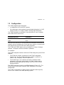
General Description . . . . . . . . . . . . . . . . . . . . . . . . . . . . . . . .
1.2
Configuration . . . . . . . . . . . . . . . . . . . . . . . . . . . . . . . . . . . . .
1.3
Node ID Label . . . . . . . . . . . . . . . . . . . . . . . . . . . . . . . . . . . .
1.4
Operating Modes . . . . . . . . . . . . . . . . . . . . . . . . . . . . . . . . . .
1.5
Hardware Components . . . . . . . . . . . . . . . . . . . . . . . . . . . . . .
1.5.1
Loader Transfer Assembly . . . . . . . . . . . . . . . . . . . . . . . . .
1.5.2
Magazine . . . . . . . . . . . . . . . . . . . . . . . . . . . . . . . . . . . . . .
1.5.3
TK86 Tape Drive . . . . . . . . . . . . . . . . . . . . . . . . . . . . . . . .
1.5.4
Controller Module . . . . . . . . . . . . . . . . . . . . . . . . . . . . . . .
1.5.5
Rear Chassis . . . . . . . . . . . . . . . . . . . . . . . . . . . . . . . . . . .
1.6
CompacTape III Cartridge . . . . . . . . . . . . . . . . . . . . . . . . . . .
1.6.1
Selecting Density with the TF867 . . . . . . . . . . . . . . . . . . .
1.6.1.1
Using the FORCEDENSITY Parameter . . . . . . . . . . . . .
1.6.2
Cartridge Reliability . . . . . . . . . . . . . . . . . . . . . . . . . . . . .
1.7
Specifications . . . . . . . . . . . . . . . . . . . . . . . . . . . . . . . . . . . . .
1.8
Supplies and Related Documents . . . . . . . . . . . . . . . . . . . . . .
2
1–1
1–3
1–5
1–8
1–10
1–10
1–12
1–12
1–12
1–12
1–13
1–14
1–14
1–15
1–16
1–18
Operation
2.1
2.2
2.2.1
2.2.2
2.3
2.4
2.4.1
2.4.2
2.4.3
2.4.4
Power-On Process . . . . . . . . . . . . . . . . . . . . . . . . . . .
Mode Select Key . . . . . . . . . . . . . . . . . . . . . . . . . . . . .
Operating Modes . . . . . . . . . . . . . . . . . . . . . . . . . .
Service Mode . . . . . . . . . . . . . . . . . . . . . . . . . . . . .
Operator Control Panel . . . . . . . . . . . . . . . . . . . . . . .
Slot Select, Load/Unload, and Eject Button Functions
Selecting a Cartridge . . . . . . . . . . . . . . . . . . . . . . .
Loading the Cartridge . . . . . . . . . . . . . . . . . . . . . .
Unloading the Cartridge . . . . . . . . . . . . . . . . . . . .
Opening the Receiver . . . . . . . . . . . . . . . . . . . . . . .
.
.
.
.
.
.
.
.
.
.
.
.
.
.
.
.
.
.
.
.
.
.
.
.
.
.
.
.
.
.
.
.
.
.
.
.
.
.
.
.
.
.
.
.
.
.
.
.
.
.
.
.
.
.
.
.
.
.
.
.
2–1
2–2
2–2
2–4
2–4
2–6
2–6
2–6
2–7
2–7
iii
iv Contents
2.5
Magazine . . . . . . . . . . . . . . . . . . . . . . . . . . . . . . . . . . .
2.5.1
Inserting a Cartridge into the Front of the Magazine
2.5.2
Removing a Cartridge from the Magazine . . . . . . . . .
2.5.3
Removing the Magazine from the Receiver . . . . . . . .
2.5.4
Installing the Magazine into the Receiver . . . . . . . . .
3
.
.
.
.
.
.
.
.
.
.
. 2–8
. 2–8
. 2–11
. 2–11
. 2–11
TF867 Local Programs
3.1
3.1.1
3.2
3.3
3.4
3.4.1
3.4.2
3.4.3
3.4.4
3.4.5
3.4.6
3.4.7
3.5
3.6
3.7
4
.
.
.
.
.
Accessing Local Programs . . . . . . . . . . . . . . . . . . . . . . . . . . . 3–2
Error Message after Executing SET HOST/DUP Command 3–3
DIRECT Utility . . . . . . . . . . . . . . . . . . . . . . . . . . . . . . . . . . . 3–3
HISTRY Program . . . . . . . . . . . . . . . . . . . . . . . . . . . . . . . . . . 3–4
PARAMS Program . . . . . . . . . . . . . . . . . . . . . . . . . . . . . . . . . 3–5
Displaying, Setting, and Saving Parameters . . . . . . . . . . . 3–6
HELP Command . . . . . . . . . . . . . . . . . . . . . . . . . . . . . . . . 3–6
SHOW Command . . . . . . . . . . . . . . . . . . . . . . . . . . . . . . . . 3–7
SET Command . . . . . . . . . . . . . . . . . . . . . . . . . . . . . . . . . . 3–8
STATUS Command . . . . . . . . . . . . . . . . . . . . . . . . . . . . . . 3–8
WRITE Command . . . . . . . . . . . . . . . . . . . . . . . . . . . . . . . 3–9
EXIT Command . . . . . . . . . . . . . . . . . . . . . . . . . . . . . . . . . 3–9
DRVEXR Program . . . . . . . . . . . . . . . . . . . . . . . . . . . . . . . . . 3–10
DRVTST Utility . . . . . . . . . . . . . . . . . . . . . . . . . . . . . . . . . . . 3–10
LDRTST Program . . . . . . . . . . . . . . . . . . . . . . . . . . . . . . . . . 3–11
Error Conditions and Problem Resolutions
4.1
Conditions Necessary for Button Operation
4.2
Backup Operation Failure . . . . . . . . . . . . .
4.3
Avoiding Basic Problems . . . . . . . . . . . . . .
4.4
Error Conditions . . . . . . . . . . . . . . . . . . . .
4.4.1
Magazine Fault Description . . . . . . . . . .
4.4.1.1
Clearing a Magazine Fault . . . . . . . . .
4.4.2
Loader Fault Description . . . . . . . . . . . .
4.4.2.1
Clearing a Loader Fault . . . . . . . . . . .
4.5
Power Problems . . . . . . . . . . . . . . . . . . . . .
.
.
.
.
.
.
.
.
.
.
.
.
.
.
.
.
.
.
.
.
.
.
.
.
.
.
.
.
.
.
.
.
.
.
.
.
.
.
.
.
.
.
.
.
.
.
.
.
.
.
.
.
.
.
.
.
.
.
.
.
.
.
.
.
.
.
.
.
.
.
.
.
.
.
.
.
.
.
.
.
.
.
.
.
.
.
.
.
.
.
.
.
.
.
.
.
.
.
.
.
.
.
.
.
.
.
.
.
.
.
.
.
.
.
.
.
.
.
.
.
.
.
.
.
.
.
4–1
4–3
4–3
4–4
4–5
4–5
4–6
4–6
4–6
Contents v
5
Head Cleaning
5.1
Accessing the Tape Drive . . . . . . . . . . . . . . . . . . . . . . . . . . .
5.1.1
Loading the CleaningTape III Cartridge into the Drive . .
5.1.2
Securing the Tx867 Magazine Tape Subsystem . . . . . . . .
5.2
Inserting the CleaningTape III Cartridge into the Magazine
A
VMS Operating System Commands
A.1 Tape Device Specific Commands
A.1.1
ALLOCATE Command . . . . . .
A.1.2
DEALLOCATE Command . . .
A.1.3
BACKUP Command . . . . . . . .
A.1.4
MOUNT Command . . . . . . . .
A.1.5
COPY Command . . . . . . . . . .
A.1.6
DISMOUNT Command . . . . .
A.1.7
INITIALIZE Command . . . . .
B
. 5–6
. 5–9
. 5–9
. 5–11
.
.
.
.
.
.
.
.
.
.
.
.
.
.
.
.
.
.
.
.
.
.
.
.
.
.
.
.
.
.
.
.
.
.
.
.
.
.
.
.
.
.
.
.
.
.
.
.
.
.
.
.
.
.
.
.
.
.
.
.
.
.
.
.
.
.
.
.
.
.
.
.
.
.
.
.
.
.
.
.
.
.
.
.
.
.
.
.
.
.
.
.
.
.
.
.
.
.
.
.
.
.
.
.
.
.
.
.
.
.
.
.
.
.
.
.
.
.
.
.
.
.
.
.
.
.
.
.
.
.
.
.
.
.
.
.
.
.
.
.
.
.
.
.
.
.
.
.
.
.
.
.
.
.
.
.
.
.
.
.
.
.
.
.
.
.
.
.
.
.
.
.
.
.
.
.
A–1
A–2
A–2
A–2
A–3
A–4
A–4
A–5
Using the TZ867 Subsystem with the ULTRIX Operating
System
B.1 Adding the TZ867 to the ULTRIX System . . . . . . . . . . . . . .
B.1.1
Connecting the TZ867 to ULTRIX . . . . . . . . . . . . . . . . . .
B.1.2
Checking the ULTRIX System Configuration File . . . . . .
B.1.3
Creating an Entry . . . . . . . . . . . . . . . . . . . . . . . . . . . . . .
B.1.4
Building the Kernel, Rebooting the System . . . . . . . . . . .
B.1.5
Creating Logical Device Names for the TZ867 Subsystem
B.2 Getting Maximum Capacity and Performance . . . . . . . . . . .
B.2.1
Getting Maximum Storage Capacity . . . . . . . . . . . . . . . .
B.2.2
Maximizing Performance . . . . . . . . . . . . . . . . . . . . . . . . .
B.3 Doing Unattended Backups . . . . . . . . . . . . . . . . . . . . . . . . .
B.3.0.1
Developing Unattended Backup Shell Scripts . . . . . . .
B.4 Selecting Density . . . . . . . . . . . . . . . . . . . . . . . . . . . . . . . . .
B.5 Using ULTRIX Tape Commands . . . . . . . . . . . . . . . . . . . . .
B.5.1
Using the tar Command . . . . . . . . . . . . . . . . . . . . . . . . . .
B.5.2
Using the dump Command . . . . . . . . . . . . . . . . . . . . . . .
B.5.3
Using the restore Command . . . . . . . . . . . . . . . . . . . . . .
B.5.4
Using the dd Command . . . . . . . . . . . . . . . . . . . . . . . . . .
. B–1
. B–2
. B–2
. B–2
. B–3
. B–3
. B–4
. B–5
. B–5
. B–6
. B–6
. B–8
. B–9
. B–9
. B–10
. B–10
. B–11
vi Contents
B.5.5
B.5.6
B.5.7
C
C.1
C.2
C.3
C.4
C.5
C.6
Using the ltf Command . . . . . . . . . . . . . . . . . . . . . . . . . . . B–12
Using the mt Command . . . . . . . . . . . . . . . . . . . . . . . . . . . B–13
Using the cpio Command . . . . . . . . . . . . . . . . . . . . . . . . . . B–13
Service Offerings
On-Site Service . . .
BASIC Service . . . .
DECservice Plan . .
Carry-In Service . . .
DECmailer Service .
Per Call Service . . .
.
.
.
.
.
.
.
.
.
.
.
.
.
.
.
.
.
.
.
.
.
.
.
.
.
.
.
.
.
.
.
.
.
.
.
.
.
.
.
.
.
.
.
.
.
.
.
.
.
.
.
.
.
.
.
.
.
.
.
.
.
.
.
.
.
.
.
.
.
.
.
.
.
.
.
.
.
.
.
.
.
.
.
.
.
.
.
.
.
.
.
.
.
.
.
.
.
.
.
.
.
.
.
.
.
.
.
.
.
.
.
.
.
.
.
.
.
.
.
.
.
.
.
.
.
.
.
.
.
.
.
.
.
.
.
.
.
.
.
.
.
.
.
.
.
.
.
.
.
.
.
.
.
.
.
.
.
.
.
.
.
.
.
.
.
.
.
.
.
.
.
.
.
.
.
.
.
.
.
.
.
.
.
.
.
.
.
.
.
.
.
.
C–1
C–1
C–1
C–2
C–2
C–2
Front View of the Tx867 Magazine Tape Subsystem . .
SF200 Storage Array . . . . . . . . . . . . . . . . . . . . . . . . . .
SF106/SZ106 Pedestal . . . . . . . . . . . . . . . . . . . . . . . . .
Tx867 Subsystem Mode Select Key Symbols . . . . . . . .
Tx867 Magazine Tape Subsystem Block Diagram . . . .
CompacTape III Cartridge . . . . . . . . . . . . . . . . . . . . . .
Tx867 Operator Control Panel . . . . . . . . . . . . . . . . . . .
Write-Protect Switch on a Cartridge . . . . . . . . . . . . . .
Inserting a Cartridge into the Magazine . . . . . . . . . . .
Removing a Cartridge from the Front of the Magazine
Receiver Opened . . . . . . . . . . . . . . . . . . . . . . . . . . . . .
Opening the Cartridge Door to Check the Tape Leader
CleaningTape III Cartridge . . . . . . . . . . . . . . . . . . . . .
Drive Front Panel . . . . . . . . . . . . . . . . . . . . . . . . . . . .
Tx867 Operator Control Panel . . . . . . . . . . . . . . . . . . .
Sliding the Tx867 Subsystem Toward You . . . . . . . . . .
Loader Open Latch . . . . . . . . . . . . . . . . . . . . . . . . . . .
Loading the Cartridge . . . . . . . . . . . . . . . . . . . . . . . . .
.
.
.
.
.
.
.
.
.
.
.
.
.
.
.
.
.
.
.
.
.
.
.
.
.
.
.
.
.
.
.
.
.
.
.
.
.
.
.
.
.
.
.
.
.
.
.
.
.
.
.
.
.
.
.
.
.
.
.
.
.
.
.
.
.
.
.
.
.
.
.
.
.
.
.
.
.
.
.
.
.
.
.
.
.
.
.
.
.
.
1–2
1–6
1–7
1–9
1–11
1–13
2–3
2–9
2–10
2–12
2–13
4–4
5–2
5–4
5–5
5–7
5–8
5–10
Index
Figures
1–1
1–2
1–3
1–4
1–5
1–6
2–1
2–2
2–3
2–4
2–5
4–1
5–1
5–2
5–3
5–4
5–5
5–6
Contents vii
Tables
1–1
1–2
1–3
1–4
1–5
1–6
2–1
3–1
3–2
4–1
B–1
B–2
B–3
B–4
B–5
B–6
B–7
B–8
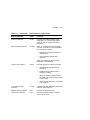
TZ867 VMS Restrictions . . . . . . . . . . . . . . . . . . . . . . . . .
Read/Write Cartridge Compatibility with the TK86 Drive
Tx867 Magazine Tape Subsystem Specifications . . . . . . .
TK86 Tape Drive Specifications . . . . . . . . . . . . . . . . . . . .
Supplies . . . . . . . . . . . . . . . . . . . . . . . . . . . . . . . . . . . . . .
Related Documents . . . . . . . . . . . . . . . . . . . . . . . . . . . . .
Tx867 Operator Control Panel . . . . . . . . . . . . . . . . . . . . .
TF867 Subsystem Parameters . . . . . . . . . . . . . . . . . . . . .
TF867 PARAMS Commands . . . . . . . . . . . . . . . . . . . . . .
Tx867 OCP Button Conditions . . . . . . . . . . . . . . . . . . . . .
Determining the Tape Name . . . . . . . . . . . . . . . . . . . . . .
Common tar Options . . . . . . . . . . . . . . . . . . . . . . . . . . . .
Common dump Options . . . . . . . . . . . . . . . . . . . . . . . . . .
Common restore Options . . . . . . . . . . . . . . . . . . . . . . . .
Common dd Options . . . . . . . . . . . . . . . . . . . . . . . . . . . . .
Common ltf Options . . . . . . . . . . . . . . . . . . . . . . . . . . . . .
Common mt Options . . . . . . . . . . . . . . . . . . . . . . . . . . . .
Common cpio Options . . . . . . . . . . . . . . . . . . . . . . . . . . .
.
.
.
.
.
.
.
.
.
.
.
.
.
.
.
.
.
.
.
.
.
.
.
.
.
.
.
.
.
.
.
.
.
.
.
.
.
.
.
.
.
.
.
.
.
.
.
.
.
.
.
.
.
.
1–4
1–14
1–16
1–17
1–18
1–18
2–4
3–5
3–6
4–2
B–3
B–9
B–10
B–11
B–11
B–12
B–13
B–14
Preface
Purpose
This manual introduces the Tx867 series of magazine tape subsystems
and describes operating procedures.
Manual Structure
Chapter 1, Overview, provides a basic product description of and
specifications for the Tx867 series magazine tape subsystem.
Chapter 2, Operation, describes the power-on process, the keys and
indicators on the operator control panel (OCP), the operating modes
of the Mode Select key, and the magazine and cartridge removal and
replacement processes.
Chapter 3, TF867 Local Programs, describes how to access local diagnostic
programs on the TF867 subsystem using the SET HOST/DUP command.
Chapter 4, Error Conditions and Problem Resolutions, describes the
necessary conditions to use OCP buttons, backup operation failures, error
indications, and power problems.
Chapter 5, Head Cleaning, describes how to clean the read/write heads in
the tape drive.
Appendix A, VMS Operating System Commands, describes VMS
commands used with tape devices.
Appendix B, Using the TZ867 Subsystem with the ULTRIX Operating
System, describes how to add the TZ867 subsystem to your ULTRIX
operating system, how to get maximum capacity and performance from
the TZ867 subsystem, using the TZ867 for unattended backups, and using
various ULTRIX commands to save information on the TZ867 subsystem.
Appendix C, Service Offerings, describes maintenance plans offered by
Digital Services.
ix
x Preface
Intended Audience
This manual is intended for the TF867 or TZ867 subsystem owner.
This manual is for use by system managers, computer operators, or
anyone who uses magazine tape subsystems. Prior knowledge of and
experience with the VMS operating system and commands and tape
devices are required.
Conventions
The term Tx867 refers to the TF867 and the TZ867 magazine tape
subsystems.
The term OCP pushbuttons refers to the Eject, Load/Unload, and Slot
Select buttons that are at the top of the operator control panel (OCP) on
the Tx867 subsystem.
1
Overview
This chapter describes the Tx867 magazine tape subsystem and its
functions.
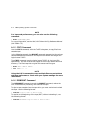
1.1 General Description
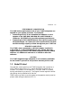
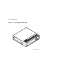
The Tx867 magazine tape subsystem (Figure 1–1) is an electromechanical
device that can store approximately 42.0 GB of data. Using
CompacTape III cartridges, the Tx867 subsystem can store up to 6.0
GB of data per cartridge.
The Tx867 magazine tape subsystem can load and unload tape cartridges
into and from a tape drive, providing a degree of unattended backup,
as well as perform single cartridge operations. The Tx867 subsystem
performs automatic, sequential tape operations.
In addition, the Tx867 subsystem executes operating system commands,
qualifiers, and parameters to store data from user disk areas to the tape
drive.
1–1
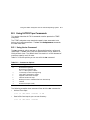
1–2 Overview
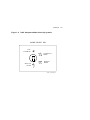
Figure 1–1 Front View of the Tx867 Magazine Tape Subsystem
O PERAT O R CO NT RO L PANEL
Eject
Load/Unload
MOD E S E LE C T K E Y
BUTTON
AND
INDICATOR
AREA
Slot Select
OCP
DISABLED
0
AUTOMATIC
MODE
Power On
OCP LABEL
CURRENT
SLOT
INDICATORS
0-6
Write
Protected
Tape In Use
1
MANUAL
MODE
Use
Cleaning Tape
SERVICE
MODE
Magazine
Fault
Loader Fault
2
Eject
3
DSSI NODE
ID LABEL
(TF867 ONLY)
Load/Unload
Slot Select
0
Power On
Write
Protected
Write Protect
Load Fault
1
Tape In Use
Use
Cleaning Tape
4
Magazine
Fault
Loader Fault
2
3
5
4
5
6
6
40% REDUCTION
SHR_X1025E_91
Overview 1–3
1.2 Configuration
The Tx867 magazine tape subsystem:
•
Is configured on VAX and RISC systems
•
Can serve two or more systems as a dual-ported subsystem in a DSSI
cluster (TF867) or CI cluster (TA867 Cartridge Tape Subsystem)
The Tx867 subsystem is available in two variations for use on systems
with a DSSI bus or a SCSI bus:
Subsystem Variation
System Bus
TF867
DSSI
TZ867
SCSI
The DSSI bus and the SCSI bus are electrical connections that allow the
system’s central processing unit (CPU) and main memory to communicate
with devices such as the TF867 and TZ867 subsystem.
The TF867 and TZ867 options can be installed in a variety of storage
cabinets. The options are also available in pedestals.
For example:
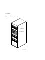
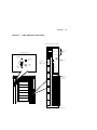
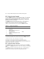
The TF867 subsystem installs in both the SF200 storage array and SF106
pedestal:
•
The SF200 can contain a maximum of two TF867 subsystems
(Figure 1–2). The first TF867 subsystem installs in position 5; a
second TF867 subsystem installs in position 6.
•
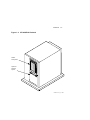
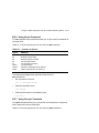
The SF106 (Figure 1–3) contains one factory-installed TF867
subsystem in the upper compartment; the lower compartment is
optional storage space that can contain an SF72, SF73, or SF35
storage enclosure.
The TZ867 subsystem installs in the SZ106 pedestal (Figure 1–3). The
SZ106 contains one factory-installed TZ867 subsystem in the upper
compartment.
The TF867 is supported as a generic device (unknown device type) by
version 5.4-2 or later of the VMS operating system.
1–4 Overview
The TZ867 is supported by various VMS versions with certain restrictions
(Table 1–1):
Table 1–1 TZ867 VMS Restrictions
VMS
Version
Restrictions1
<5.3
X
5.3
1,2,4
5.4
1,2,4
5.4-1
1,2,4
5.4-2
1,2,3,4
5.4-3
1,2,3,4
5.5
1,2,4
5.5-1
1,2,4
1 KEY
X = Not Supported
1 = VMS SHOW DEVICE command indicates "generic SCSI tape" and ERROR
LOGGING indicates "GENERIC MK SUBSYSTEM". This has little impact on most
applications.
2 = Standalone BACKUP not supported. You cannot create a standalone BACKUP tape.
3 = Sequential tape cartridge autoloading NOT supported. For example, operator
intervention is required for multivolume BACKUP.
4 = Writing COMPACTAPE III media with TK85 format is not supported, since VMS
does not support density select on the TZ86.
Overview 1–5
PERFORMANCE CONSIDERATION
The VMS backup performance rate of your Tx867 subsystem can
depend on your system processor. For example:
•
Connecting directly to an embedded bus adapter on such
systems as the VAX 4000, VAX 6000, MicroVAX 3100-80, or
InfoServer 150 (TZ867 only) provides optimum performance.
•
Connecting to a MicroVAX/VAXserver 3xxx (Q–bus) system with
a KZQSA adapter can reduce the rate of performance but does
not limit the high capacity of data storage that your Tx867 has.
REQUIRED LOAD DEVICE
The TF867, when connected to a KFQSA adapter installed in
a MicroVAX II or MicroVAX/VAXserver 3xxx system, does not
support booting of VMS or MicroVAX Diagnostic Monitor (MDM)
software. An additional load device is needed to boot this
software.
CAUTION
The Tx867 magazine tape subsystem is not customer-installable.
Do not install it yourself or the product warranty will be void.
1.3 Node ID Label
The operator control panel on the TF867 subsystem has a space for a
DSSI node ID label (Figure 1–1), which identifies the device bus ID
number. (This label is in the label kit.) The DSSI node ID is preset
during manufacturing to zero (0). The Digital Services engineer verifies
this setting during installation at the site.
TZ867 users may wish to use this space on the operator control panel to
place a label noting the device’s SCSI ID.
1–6 Overview
Figure 1–2 SF200 Storage Array
SF
20
0
POSITION 5
0
1
2
3
0
4
POSITION 6
1
5
2
6
3
4
5
6
CXO-2461B
SHR_X1106A_89
Overview 1–7
Figure 1–3 SF106/SZ106 Pedestal
TX867
Subsystem
Optional
Storage
Space
SHR-X0175_91-DG
1–8 Overview
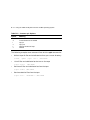
1.4 Operating Modes
The Tx867 subsystem operates in the following modes:
•
OCP Disabled mode — Locks the subsystem into the enclosure and
locks the receiver. The pushbuttons on the operator control panel
(OCP)—Eject, Load/Unload, Slot Select—are disabled. This mode
automatically loads the next tape cartridge into the drive after you
issue the DISMOUNT command.
•
Automatic mode — Is the subsystem’s default or normal mode.
It locks the subsystem into the enclosure but leaves the receiver
unlocked. This mode automatically loads the next tape cartridge
into the drive after you issue the DISMOUNT command. The OCP
pushbuttons remain enabled.
•
Manual mode — Locks the subsystem into the enclosure but
leaves the receiver unlocked. This mode allows for single cartridge
operations only. The OCP pushbuttons remain enabled. Loading and
unloading of cartridges is not automatic; operator intervention is
required to select the next cartridge.
•
Service mode — Unlocks the subsystem from the enclosure; the
subsystem is no longer in Automatic mode. This mode is for you
to use when accessing the drive for head cleaning and for Digital
Services engineers to use when performing servicing procedures.
You can select these modes through the Mode Select key (Figure 1–4) on
the front of the Tx867 subsystem.
See Chapter 2 for information on using the modes and the Mode Select
key.
Overview 1–9
Figure 1–4 Tx867 Subsystem Mode Select Key Symbols
MODE SEL E C T K E Y
OCP
DISABLED
AUTOMATIC
MODE
SERVICE
MODE
MANUAL
MODE
SHR_X1025D_89
1–10 Overview
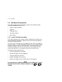
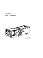
1.5 Hardware Components
The Tx867 magazine tape subsystem consists of the following major
hardware components (Figure 1–5):
•
Loader transfer assembly
•
Magazine
•
TK86 tape drive
•
Controller module
•
Rear chassis
1.5.1 Loader Transfer Assembly
The Tx867 subsystem has a loader transfer assembly that contains the
electromechanical assemblies required to store and move cartridges for
use by the TK86 tape drive.
You must insert cartridges into the magazine, then insert the magazine
into the receiver. An internal elevator mechanism, in the loader transfer
assembly, moves to each of the storage slots. The elevator loads and
unloads cartridges into the drive, and returns the cartridges to their
original storage slots in the magazine after they have been used.
The loader transfer assembly can:
•
Scan the magazine for cartridges
•
Unload cartridges from the magazine
•
Load cartridges into the drive
•
Unload cartridges from the drive
•
Restore cartridges to their original slots in the magazine
NOTE
Do not press the Load/Unload button on the Tx867 OCP to abort
functions of the loader transfer assembly. Type Ctrl/Y or Ctrl/C
instead.
Overview 1–11
Figure 1–5 Tx867 Magazine Tape Subsystem Block Diagram
DOCUMENTATION
COUNTRY
KITS
HOST
S/W
(VMS)
RACK
MOUNT
KIT
MAGAZINE
CONTROLLER
MODULE
TK86
REAR
CHASSIS
LOADER
TRANSFER
ASSEMBLY
SHR_X1009C_89
1–12 Overview
1.5.2 Magazine
The magazine is a removable storage rack that can store up to seven
CompacTape III cartridges. The magazine consists of seven slots in which
the cartridges are loaded; these slots are numbered from 0 to 6 on the
front of the magazine.
Use the OCP pushbuttons to open the receiver, insert or remove the
magazine, load or unload cartridges, or select a slot.
For more information, see Section 2.3.
1.5.3 TK86 Tape Drive
The TK86 tape drive, in the rear chassis of the Tx867 subsystem, is a
streaming tape drive that stores up to 6.0 GB of data on each of its tape
cartridges. The controller module connects the Tx867 subsystem to the
host system and initiates commands to the TK86 tape drive.
1.5.4 Controller Module
The controller module is the Tx867 subsystem’s interface to the host
system through the bus. For systems with a DSSI bus and a TF867, the
module is a DSSI controller. For systems with a SCSI bus and the TZ867,
the module is a SCSI controller. The host system initiates commands to
the Tx867 subsystem and TK86 drive through the controller module.
1.5.5 Rear Chassis
The following lists the other components found in the rear chassis and
their functions:
•
Power supply–provides power to the rear chassis components and to
the loader transfer assembly
•
Fan–cools the entire Tx867 subsystem
•
Handle motor assembly–lifts and lowers the drive’s handle when
cartridges are ready for loading into, or unloading from, the drive
•
Interlock switch–safety feature that interrupts voltage when you
access the drive for head cleaning
Overview 1–13
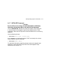
1.6 CompacTape III Cartridge
The CompacTape III cartridge (Figure 1–6) is a 4 1=8-inch square, dark
gray, plastic cartridge containing 1200 feet of 1=2-inch magnetic, metal
particle (MP) tape. The cartridge has a write-protect switch to prevent
accidental erasure of data. When the switch is moved to the left and the
small orange rectangle is visible, data cannot be written to the tape. A
package of slide-in labels and a cartridge handling information sheet are
provided with each CompacTape III cartridge.
Figure 1–6 CompacTape III Cartridge
ORANGE
INDICATOR
TM
Co
a
mp
cT
a
III
pe
WRITEPROTECT
SWITCH
WRITEENABLED
WRITEPROTECTED
SHR_X1020C_89
1–14 Overview
The TK86 tape drive writes 112 tracks (56 pairs) on the tape. The
drive reads and writes data in a two-track parallel, serpentine fashion,
traveling the entire length of tape on two tracks (at approximately 100
inches per second). The drive then steps the head and reverses tape
direction, and continues to read/write on the next two tracks.
Use Table 1–2 to determine cartridge compatibility with the TK86 drive:
Table 1–2 Read/Write Cartridge Compatibility with the TK86 Drive
Cartridge Type
Read/Write Ability in the TK86
CompacTape III (TK85)
Read/write in 85 Mode (48 tracks,
2.6 GBF)
CompacTape III (TK86)
Read/write in 86 Mode (112 tracks,
6.0 GBF)
CompacTape III (Blank)
Read/write in 86 Mode (112 tracks,
6.0 GBF)
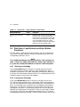
1.6.1 Selecting Density with the TF867
Operating system support of density selection is not yet available. The
TK86 tape drive defaults to using TK86 format (high density) for all
writes from Beginning of Tape (BOT). When you append data to the tape
cartridge, the current media density is used.
For information on selecting density using the TZ867 subsystem with the
ULTRIX operating system, see Appendix B.
To write in TK85 format (low density) on a TF867 subsystem, you can use
the PARAMS utility on VMS systems to modify a new DUP Parameter
named FORCEDENSITY, explained in Section 1.6.1.1.
1.6.1.1 Using the FORCEDENSITY Parameter
For explanation on starting PARAMS to use the FORCEDENSITY
parameter, see Chapter 3.
The DUP parameter FORCEDENSITY controls how a TF867
subsystem determines what density to use when writing from BOT.
FORCEDENSITY has the following possible values:
•
0 = automatic, as selected by the host
•
1 = low (TK85) density regardless of host selection
•
2 = high (TK86) density regardless of host selection
Overview 1–15
The factory setting is 2 for the FORCEDENSITY parameter. Under this
setting, the TK86 tape drive will always reformat the tape to TK86 format
on a WRITE-FROM-BOT.
Users wanting to write in TK85 format must:
•
Load a tape written in TK85 format and do APPEND operations
or
•
Change the value of FORCEDENSITY to 1 and then WRITE from
BOT.
CAUTION
Be sure to change the value of FORCEDENSITY back to 2 after
you have finished desired tape operations.
1.6.2 Cartridge Reliability
To ensure the reliability of cartridges that:
•
Contain recorded data and may be archived for a long time
•
Do not contain recorded data
store the cartridges in a clean, controlled environment with the following
conditions:
•
Environmental temperature: 18.3°C to 26.1°C (65°F to 79°F)
•
Relative humidity: 20% to 60%
1–16 Overview
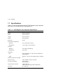
1.7 Specifications
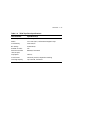
Table 1–3 lists the specifications for the Tx867 magazine tape subsystem,
and Table 1–4 lists those for the TK86 tape drive.
Table 1–3 Tx867 Magazine Tape Subsystem Specifications
Characteristic
Specifications
Height
26.47 cm (10.42 in)
Width
22.20 cm (8.74 in)
Length
64.77 cm (25.5 in)
Weight
24.95 kg (55 lb)
Noise level
62 dB
Environmental temperature
Operating
10°C to 40°C (50°F to 104°F)
Nonoperating
–40°C to 66°C (–40°F to 150.8°F)
Humidity
Operating
20% to 80% noncondensing
Nonoperating
10% to 95%
Certification
EMI
Meets applicable FCC, VDE, and FTZ standards for
Class A devices
Safety
Meets UL, CSA, TUV "BG" MARK and IEC standards
Maximum number of cartridges
7
Electrical rating
100 to 120/220 to 240 VAC, 2/1 AMP
AC power consumption
110 W, typical
113 W, maximum
Communications interface
TF867: DSSI bus
TZ867: SCSI bus (single-ended or differential)
Cycle time
50 s, maximum
Overview 1–17
Table 1–4 TK86 Tape Drive Specifications
Characteristic
Specification(s)
Mode of operation
Streaming
Media
12.77 mm (1/2 in) unformatted magnetic tape
Track density
224 tracks/in
Bit density
42,500 bits/in
Number of tracks
112
Maximum transfer
rate (at tape)
800 KB/s, formatted
Tape speed
100 in/s
Track format
Two-track parallel, serpentine recording
Cartridge capacity
Up to 6.0 GB, formatted
1–18 Overview
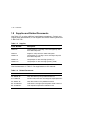
1.8 Supplies and Related Documents
Use Table 1–5 to order additional cartridges or magazines. Contact your
Digital sales representative, or call Digital’s DECdirect ordering service at
1–800–DIGITAL.
Table 1–5 Supplies
Order Number
Description
TK85–HC
CleaningTape III Cartridge. One cartridge ships with
the Tx867 subsystem.
TK85–M
Magazine. Ships with the Tx867 subsystem.
TK85K–01
CompacTape III Cartridge. Seven cartridges ship with
the Tx867 subsystem.
TK85K–07
CompacTape III data cartridge (quantity, 7)
TK85K–A0
CompacTape III data cartridge (quantity, 1008)
Use the documents in Table 1–6 as supplements to this manual.
Table 1–6 Related Documents
Order Number
Title
AA–Z407B–TE
VAX/VMS Backup Utility Reference Manual
AI–Y506B–TE
Guide to VAX/VMS Disk and Magnetic Tape Operations
AA–Z424A–TE
VAX/VMS Mount Utility Reference Manual
EK–OTX86–OM
Tx86 Series Cartridge Tape Subsystem Owner’s Manual
EK–OTK86–RC
Tx86 Tape Drive Operator’s Reference Card
2
Operation
This chapter explains Tx867 subsystem operation:
•
Power-on process
•
Mode Select key modes
•
Operator control panel (OCP) indicator functions
•
Slot Select, Load/Unload, and Eject button functions
•
Magazine cartridge insertion and removal
2.1 Power-On Process
When the Tx867 subsystem powers on, all of the indicators on the
operator control panel (OCP) light, within 15 seconds. The power-on
self-test, or POST, is initializing the subsystem. When POST completes
successfully, all OCP indicators, including the Magazine Fault and Loader
Fault indicators, turn off—except for Power On.
NOTE
If the Magazine Fault or Loader Fault indicator remains on, POST
has detected an error. See Chapter 4 for error conditions.
The elevator scans the magazine to determine which slots contain
cartridges. If the subsystem has a magazine with a cartridge in
slot 0, and no cartridge is in the drive, these indicators should be on:
Power On
Eject
Load/Unload
Slot Select
Slot 0
2–1
2–2 Operation
2.2 Mode Select Key
The Mode Select key (Figure 2–1) can lock the loader transfer assembly
into the enclosure, as well as lock the receiver closed. It has four modes:
OCP Disabled, Automatic, Manual, and Service. The OCP Disabled,
Automatic, and Manual modes are for operational use; the Service mode
is for head cleaning and servicing procedures.
2.2.1 Operating Modes
The following modes for operational use:
•
OCP Disabled mode — When the magazine is inserted into the
receiver and the receiver is closed, the loader transfer assembly scans
the magazine. The first cartridge in the magazine automatically loads
into the drive. Operations stop if you are copying data to tape and
either the storage capacity of the last tape cartridge is exceeded, or no
tape cartridge is in the next sequential slot in the magazine.
To lock the Tx867 subsystem into the enclosure and lock the
receiver, set the Mode Select key to OCP Disabled mode. The OCP
pushbuttons are disabled.
•
Automatic mode — This mode is the default, or normal, mode of
the Tx867 subsystem. It automatically loads and unloads cartridges
as necessary during backup procedures. Operations stop if you are
copying data to tape and either the storage capacity of the last tape
cartridge is exceeded, or no tape cartridge is in the next sequential
slot in the magazine.
To lock the Tx867 subsystem into its normal operating position in the
enclosure but leave the receiver unlocked, set the Mode Select key to
Automatic mode. The receiver can be opened; all OCP pushbuttons
are enabled.
•
Manual mode — Automatic loading and unloading of cartridges
does not occur in this mode; rather, you must press the Load/Unload
button to move each cartridge. This mode is most useful for, but not
restricted to, copying specific files to or from tape.
To lock the Tx867 subsystem into the enclosure, set the Mode Select
key to Manual mode. The receiver is unlocked and can be opened; all
OCP pushbuttons are on.
NOTE
During Manual mode, the cartridge returns to the magazine,
but the current Slot Select indicator does not advance forward
to the next available cartridge.
Operation 2–3
Figure 2–1 Tx867 Operator Control Panel
O PERAT O R CO NT RO L PANEL
Eject
Load/Unload
MOD E S E LE C T K E Y
BUTTON
AND
INDICATOR
AREA
Slot Select
OCP
DISABLED
0
AUTOMATIC
MODE
Power On
OCP LABEL
CURRENT
SLOT
INDICATORS
0-6
Write
Protected
Tape In Use
1
MANUAL
MODE
Use
Cleaning Tape
SERVICE
MODE
Magazine
Fault
Loader Fault
2
Eject
3
DSSI NODE
ID LABEL
(TF867 ONLY)
Load/Unload
Slot Select
0
Power On
Write
Protected
Write Protect
Load Fault
1
Tape In Use
Use
Cleaning Tape
4
Magazine
Fault
Loader Fault
2
3
5
4
5
6
6
40% REDUCTION
SHR_X1025E_91
2–4 Operation
2.2.2 Service Mode
Service mode is for performing head cleaning by manually loading the
CleaningTape III and for performing servicing procedures. See Chapter 5
for information on head cleaning.
To unlock the Tx867 subsystem from its enclosure and remove it from its
normal operating position, set the Mode Select key to Service mode. The
receiver is unlocked and can be opened.
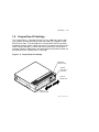
2.3 Operator Control Panel
The Tx867 operator control panel (OCP) has 3 OCP pushbuttons and
16 indicators that are used with the Mode Select key (Table 2–1). See
Section 2.2 for information on the Mode Select key and its functions. See
Section 2.4 for more details on button and indicator operations.
Table 2–1 Tx867 Operator Control Panel
Button/Indicator
Color
Function
Eject button
–
Opens the receiver, allowing access to
the magazine for removal and insertion
of cartridges. Also can be used to unload
the tape from the drive to the magazine.
Eject indicator
Green
Indicates a magazine fault, and that
you can press the Eject button to
unload cartridges from the drive to
the magazine and to open the receiver.
Load/Unload button
–
Loads the currently selected cartridge
into the tape drive. Unloads the
cartridge currently in the tape drive.
Resets the subsystem if there is a loader
fault.
Load/Unload indicator
Green
Indicates that you can press the Load
/Unload button.
Slot Select button
–
Increments the current slot indicator to
the next slot.
Slot Select indicator
Green
Indicates that you can press the Slot
Select button. Pressing this button
moves the current slot indicator to the
next slot.
Operation 2–5
Table 2–1 (Continued) Tx867 Operator Control Panel
Button/Indicator
Color
Function
Power On indicator
Green
Indicates the Tx867 magazine tape
subsystem is in a known good power
state (ac and dc voltages are within
tolerance).
Write Protected indicator
Orange
When on, indicates that the cartridge
currently in the drive is write-protected
by one of these methods:
•
Setting the write-protect switch to
write-protect
•
Using software write-protect
qualifiers
When off, indicates that the current
cartridge is write-enabled.
Tape In Use indicator
Yellow
Indicates tape drive activity as follows:
•
Slow blinking indicates tape is
rewinding.
•
Rapid blinking indicates tape is
reading or writing.
•
When on steadily, indicates that a
cartridge is in the drive and the tape
is not moving.
•
When off, indicates that no cartridge
is in the drive.
Use Cleaning Tape
indicator
Orange
Indicates that the read/write head needs
cleaning. See Chapter 5.
Magazine Fault indicator
Red
Indicates a magazine failure.
Loader Fault indicator
Red
Indicates a loader transfer assembly
error or drive error.
2–6 Operation
Table 2–1 (Continued) Tx867 Operator Control Panel
Button/Indicator
Color
Function
Current slot indicators
0–6
Green
Identifies the current slot (see Slot Select
button). Each current slot indicator
blinks when its corresponding cartridge
moves to or from the drive. Also used
with the Magazine Fault or Loader
Fault indicator to show the type of fault
(Sections 4.4.1 and Section 4.4.2).
2.4 Slot Select, Load/Unload, and Eject Button
Functions
The Slot Select, Load/Unload and Eject buttons are OCP pushbuttons.
They contain a green indicator, and they are operable only when their
corresponding indicators are on.
NOTE
The Load/Unload button has three functions: load, unload, and
reset. If there is a loader fault and the Loader Fault indicator is
on, press the Load/Unload button to reset the Tx867 subsystem.
2.4.1 Selecting a Cartridge
Use the Slot Select button to select a cartridge; press this button
to advance the slot indicator light to the next available slot. After a
successful initialization, the Tx867 subsystem automatically selects slot
0 and the Slot Select button becomes active. The Load/Unload and Eject
indicators remain on during the slot selection.
2.4.2 Loading the Cartridge
Press the Load/Unload button to load the cartridge into the drive.
This action causes the Select Slot, Load/Unload, and Eject indicators to
turn off, and the elevator to move to the selected slot, indicated by the
light. The cartridge is then removed from the magazine and placed in
the elevator. The elevator moves to the drive position and inserts the
cartridge into the drive. The indicators remain off until the tape has
loaded to the beginning of the tape (BOT). After the cartridge is loaded
into the drive, the Eject and Load/Unload indicators turn on, and the
corresponding buttons are enabled. The Slot Select indicator remains off.
Operation 2–7
2.4.3 Unloading the Cartridge
CAUTION
Do not press the Load/Unload button until backup or other tape
operations are stopped at the terminal. Doing so can result in
operation failure and drive unavailability.
When you press the Load/Unload button, the Select Slot, Load/Unload,
and Eject indicators turn off, and the cartridge unloads from the drive
into the magazine. However, automatic operation now stops and the
Select Slot operation does not increment. The indicators turn on once the
cartridge is returned to the magazine.
The Load/Unload indicator must be on before you press the button to
load or unload a cartridge. If the Loader Fault indicator is on, showing a
malfunction, press the Load/Unload button to reset the subsystem and try
to clear the error.
2.4.4 Opening the Receiver
The Eject button opens the receiver for insertion or removal of the
magazine. It is disabled when the Mode Select key is in the OCP Disabled
position. The Eject button can also be used to unload a tape from the
drive.
NOTE
When a cartridge is not in the drive, the Slot Select, Load/Unload,
and Eject indicators are on before any operation begins. Pressing
the Eject button causes all indicators to turn off. The elevator
then returns to its home position and the receiver opens.
When a cartridge is in the drive, the Eject and Load/Unload
indicators are on before the operation begins. When you press the
Eject button, both indicators turn off, and the cartridge unloads
from the drive and moves back into the magazine. The receiver
then opens to allow access to the magazine.
In both situations, once the receiver is closed again, a magazine
scan begins, and the indicators turn back on when the scan is
complete.
2–8 Operation
2.5 Magazine
The front of the magazine has numbers, 0 through 6, that indicate the
number of the slot.
NOTE
Insert and remove all cartridges at the front of the magazine.
2.5.1 Inserting a Cartridge into the Front of the Magazine
To simplify cartridge insertion, place the magazine on a flat surface with
the slots facing you (Figure 2–3). Each slot is numbered—to ensure that
you are inserting the cartridge correctly in the front of the magazine.
Usually, cartridges are inserted into consecutive slots.
To insert a cartridge into the magazine:
1. Grasp the cartridge with the CompacTape III label facing up and the
write-protect switch facing you (Figure 2–2).
2. Set the cartridge’s write-protect switch to the desired position. If
you want to write on the tape, slide the switch to the right (orange
indicator is not visible). If you want to write-protect the tape, slide
the switch to the left (orange indicator is visible).
3. Insert the cartridge (Figure 2–3) by pushing it into the slot until you
hear a click. A small metal tab holds the cartridge in place.
Operation 2–9
Figure 2–2 Write-Protect Switch on a Cartridge
ORANGE
INDICATOR
TM
C
p
om
ac
Ta
III
pe
WRITEPROTECT
SWITCH
WRITEENABLED
WRITEPROTECTED
SHR_X1020C_89
2–10 Operation
Figure 2–3 Inserting a Cartridge into the Magazine
BACK OF
MAGAZINE
TM
m
Co
pa
cT
ap
II
eI
0
1
2
3
4
5
5
6
1
2
3
0
0
1
1
2
2
3
3
4
4
5
5
6
6
NOTE: Push tape in
until a click is heard
SLOT
NUMBERS
0-6
FRONT OF
MAGAZINE
SHR_X1021_89
Operation 2–11
2.5.2 Removing a Cartridge from the Magazine
To remove a cartridge from the magazine, press the cartridge (Figure 2–4)
at the front of the magazine until you hear a click; then, release. The slot
uses a spring-release action. When you press the cartridge in all the way,
it pops out.
NOTE
Never apply labels to the top or bottom of tape cartridges. Doing
so can cause cartridge jams in the Tx867 subsystem. Use the space
on the front of the cartridge for labels. If a jam occurs, call your
Digital Services representative.
2.5.3 Removing the Magazine from the Receiver
To remove the magazine from the receiver, first be sure that:
1. The Power On indicator is on (Figure 2–1).
2. The tape drive is unloaded.
3. The Eject indicator is on. (It must be on before you can press the
Eject button.)
Then:
1. Press the Eject button (Figure 2–1) to open the receiver.
2. Grasp the receiver after it opens (Figure 2–5), and gently pull it
forward to access the magazine.
3. Grasp the magazine’s handle only to lift the magazine out of the
receiver.
2.5.4 Installing the Magazine into the Receiver
To install the magazine into the receiver:
1. Slide the magazine down into the receiver (Figure 2–5) while holding
the magazine by the handle. Since the magazine is slotted, you can
restore it in the correct orientation only.
2. Push the receiver closed.
3. Observe that the receiver is fully closed in the Tx867 subsystem before
proceeding.
2–12 Operation
Figure 2–4 Removing a Cartridge from the Front of the Magazine
BACK OF
MAGAZINE
0
1
2
NOTE: Push tape in
until a click is heard
3
4
5
6
1
TM
Co
mp
ac
Ta
pe
II
2
3
TM
0
Co
mp
ac
Ta
pe
II
0
1
2
1
3
2
4
4
3
5
5
4
6
5
6
SLOT
NUMBERS
0-6
FRONT OF
MAGAZINE
SHR_X1022_89
Operation 2–13
Figure 2–5 Receiver Opened
FRONT
BEZEL
Ejec
Loa
Slot
Pow
Wri
t
d/U
nloa
Sele
er O
n
te P
ro
Tap
tect
e In
Use
Use
Cle
anin
Driv
Loa
d
ct
g Ta
p
e
e Fa
ult
d Fa
u
lt
SHR-X0046-90
3
TF867 Local Programs
This chapter is for TF867 users only. It describes some of the local
diagnostic programs and utilities that you can access with the TF867
magazine tape subsystem to test and verify that the subsystem is
functioning correctly.
The programs and utilities, also called task names, described in this
chapter are:
•
DIRECT — Provides a directory of available local programs.
•
HISTRY — Displays information about the TF867 subsystem.
•
PARAMS — Allows you to observe and change subsystem parameters.
•
DRVEXR — Exercises the tape drive and displays statistics after
successful completion.
•
DRVTST — Verifies the correct functioning of drive hardware.
•
LDRTST — Exercises the internals of the loader transfer assembly.
NOTE
To abort a local program or utility, type Ctrl/Y or Ctrl/C . Do not stop
diagnostics by pressing the Load/Unload button on the TF867
operator control panel. Doing so can cause system failure.
3–1
3–2 TF867 Local Programs
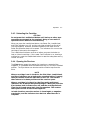
3.1 Accessing Local Programs
Access local programs with the VMS command:
$ SET HOST/DUP
You need certain VMS privileges to use the SET HOST/DUP command.
(See your system manager.) This command allows you to access the
local programs that reside in read-only memory (ROM) on the TF867
subsystem.
When you execute SET HOST/DUP, communications between the host
system and the TF867 subsystem are through diagnostic utilities protocol
(DUP). Drive operations under DUP are controlled through the local
programs. When you exit the program, control returns to the operating
system.
The following example shows the sequence of commands to access local
programs. These commands are for the VMS operating system, version
5.4-2 or later:
$ SHOW CLUSTER
(Shows the node name of the tape device.)
$ SET DEVICE/noavailable device-name
(Makes the device unavailable to users.)
$ SET HOST/DUP/SERVER=MSCP$DUP/TASK=PARAMS nodename
(Allows you to access programs.)
TASK in the above example refers to one of the six programs listed at the
beginning of this chapter. PARAMS is the program or task name. You
can use any of the program names, depending on what task you want to
accomplish.
Add the qualifier /LOG if you want a record, or log, of the results of the
test run.
CAUTION
The node name is derived from the subsystem’s serial number. If
you change the node name, the host system does not recognize
this name until you reboot the host system.
TF867 Local Programs 3–3
3.1.1 Error Message after Executing SET HOST/DUP
Command
If you receive an error message when using the SET HOST/DUP
command, you may need to load the FYDRIVER program.
To load the FYDRIVER program:
$ MCR SYSGEN
(Accesses SYSGEN.)
$ SYSGEN> LOAD FYDRIVER
(Loads FYDRIVER, a prerequisite to using diagnostics.)
$ SYSGEN> CON FYA0/NOADAP
(Configures FYDRIVER.)
$ SYSGEN> EXIT
3.2 DIRECT Utility
The DIRECT utility provides a directory of the diagnostic and utility
programs that are resident in the TF867 subsystem.
An example of a DIRECT display follows:
DIRECT V1.0 D
HISTRY V1.0 D
PARAMS V1.0 D
DRVEXR V1.0 SD
DRVTST V1.0 SD
LDRTST V1.0 SD
Completed
3–4 TF867 Local Programs
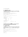
3.3 HISTRY Program
The HISTRY program displays information about the history of the
TF867 subsystem.
An example of the HISTRY display follows:
TF86
DSSI: T8BBBB /0 (DIPs)
Controller:
S#: EN03000193
HW: 000/PCB-rev:A000
Bt: 123/A435BAC1 (25-NOV-1991 16:51:54)
Cd: V004/5150C0EA (1-SEP-1992 20:33:02)
EE: 086.016 TD: 002
Drive:
S#: EN04500420
HW: 000/A000
Cd: 064/935C
EE: 001/E826
Loader (S/H/M): 028/000/000
Power on Hours: 1286
Power Cycles:
17
Completed
TF867 Local Programs 3–5
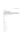
3.4 PARAMS Program
The PARAMS program displays or changes internal parameters for the
TF867 magazine tape subsystem (Table 3–1). Parameters are preset
during manufacturing; however, your system manager may need to
change them with the PARAMS program to configure your system.
Table 3–1 TF867 Subsystem Parameters
Parameter
Definition
UNITNUM
TMSCP unit number.
SYSTEMID
Controller module’s 48-bit system ID.
NODENAME
Node name for the TF867 subsystem.
FORCENAME
1 — Default node name in use. (Derived from the subsystem
serial number.)
0 — Uses value set in NODENAME.
FORCEUNI
Determines whether the TMSCP unit number or DSSI node
ID is used.
1 — Uses the DSSI node ID.
0 — Uses the TMSCP unit number.
3–6 TF867 Local Programs
3.4.1 Displaying, Setting, and Saving Parameters
Use the SET HOST/DUP command to invoke the PARAMS program. The
terminal displays the following prompt:
PARAMS>
Once you invoke the PARAMS program, all interaction is through
commands and responses (Table 3–2).
Table 3–2 TF867 PARAMS Commands
Command
Definition
HELP
Shows all PARAMS commands and their syntax.
SHOW
Displays subsystem parameters.
SET
Sets a parameter to a value.
STATUS
Displays the status of subsystem operations.
WRITE
Records the device parameters changed with the SET
command.
EXIT
Terminates the PARAMS local program.
3.4.2 HELP Command
Use the HELP command to display a list of available PARAMS
commands:
PARAMS> HELP
The PARAMS program responds:
EXIT
HELP
SET {parameter | .} value
SHOW {parameter | . | /class}
/ALL
/DIF
/DSSI
/DUP
/SYSTEM
/TDS /TMSCP
STATUS DATALINK {Reset}
STATUS PATH node_number {Reset}
STATUS LOGS
STATUS DIRECTORY
WRITE
TF867 Local Programs 3–7
3.4.3 SHOW Command
Use the SHOW command to display TF867 subsystem parameters. The
command syntax for displaying specific parameters is:
PARAMS> SHOW parameter
See Table 3–1 for the parameters you can display.
You can add qualifiers to the SHOW command to display classes of
parameter information:
•
SHOW /ALL
•
SHOW /DIF
•
SHOW /DSSI
•
SHOW /DUP
•
SHOW /SYSTEM
•
SHOW /TDS
•
SHOW /TMSCP
NOTE
Be sure to leave a space between the SHOW command and the
/qualifier.
For example, to display the settings of all the TF867 subsystem
parameters, use SHOW /ALL.
To display system parameters, type:
PARAMS> SHOW /SYSTEM
The system displays:
Parameter
Current
Default
Minimum Maximum
--------------- -------------- -------------- -------- -------FORCEEEREBUILD
0
0
0
1
CNTHWREV
0
0
0
255
HWREVSTRING
"PCB-rev:A000" "PCB-rev:????"
RGTTAG
"??????"
"??????"
UNITID
454E0044ABC4
exit
Completed
Radix
------Decimal
Decimal
Ascii
Ascii
Quad
3–8 TF867 Local Programs
3.4.4 SET Command
Use the SET command to set, or change, internal TF867 subsystem
parameters. The syntax for the SET command is:
PARAMS> SET parameter value
In the previous example, parameter is the name of the parameter to
be set, and value is the value you want to assign to the parameter. If
abbreviated, the first matching parameter is used without regard to
uniqueness.
See Table 3–1 for a summary of TF867 subsystem parameters available
when using the SET command.
CAUTION
If you type EXIT at the PARAMS> prompt without saving your
modifications, the system displays the message:
Parameter modified but not written.
Still Exit? [Y/(N)]
If you answer YES, the system returns to the VMS prompt ($).
Your modifications are not saved.
If you answer NO, the system returns to the PARAMS> prompt.
To save your modifications, enter WRITE at the prompt, and
then EXIT. See Section 3.4.6 for more information on the WRITE
command.
3.4.5 STATUS Command
The STATUS command provides status about the operation of the
subsystem.
TF867 Local Programs 3–9
3.4.6 WRITE Command
Use the WRITE command to save, in nonvolatile memory, the changes
you made using PARAMS and its SET command. The WRITE command
is similar to the VMS SYSGEN WRITE command. Syntax is as follows
(no parameters are available):
PARAMS> WRITE
The program responds:
PARAMS> SET NODENAME TAPE1
PARAMS> SET UNITNUM 18
PARAMS> WRITE
Changes require controller initialization, ok? [Y/(N)] Y
This sets the TF867 subsystem’s node name to TAPE1, and the TMSCP
unit number to 18. Executing WRITE, and answering Y(es) to the
question saves the node name and unit number in EEPROM.
NOTE
When you answer Y(es) to the controller initialization prompt,
your changes take effect immediately and program control
returns to the VMS command prompt ($).
3.4.7 EXIT Command
The EXIT command ends the PARAMS program. The word Completed
appears on the screen.
NOTE
To exit from questions in the local program, type EXIT. Do not
stop local programs by pressing the Load/Unload button on the
TF867 OCP. Doing so can cause the current operation to fail.
3–10 TF867 Local Programs
3.5 DRVEXR Program
The DRVEXR program exercises the tape drive. It is an intensive data
transfer test and indicates the overall integrity of the drive. An example
of a DRVEXR display follows:
Write/read anywhere on medium? [1=Yes/(0=No)] 1
User Data will be corrupted. Proceed? [1=Yes/(0=No)] 1
Test Time in Minutes [(10) - 100] 10
Minutes to Complete: 10
Data Compares enabled. DIAGNOSTIC TAG parameters used.
Stat Report
Test Name: DRVEXR, Pass 1
Random Seed:
1528813760
Byte Count:
0
Pattern Number:
9
Data Errors:
Read
Write
Retries:
0
1
ECC:
13
Hard:
0
0
Data Compare Errors:
0
Mispositions:
0
Kbytes Written:
189591
Read:
94379
Test Passed
NOTE
The DRVEXR program prompts you for an execution time; the
DRVTST program displays a specific execution time.
3.6 DRVTST Utility
The DRVTST utility is a pass/fail test that invokes a comprehensive test
of the drive hardware. A Test Complete message or a fatal error message
appears when the test is complete. An example of a DRVTST display
follows:
Write/read anywhere on medium? [1=Yes/(0=No)] 1
User Data will be corrupted. Proceed? [1=Yes/(0=No)] 1
Minutes to Complete: 5
Data Compares enabled. DIAGNOSTIC TAG parameters used.
Tape Mark Enc.
At LEOT
Tape Mark Enc.
TF867 Local Programs 3–11
Long Gap Found
Test Passed
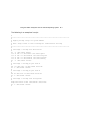
3.7 LDRTST Program
The LDRTST program sends commands to the loader electronics module,
which exercises the mechanics of the loader transfer assembly. In
addition, this test checks the status of each cartridge in the magazine. An
example of a LDRTST display follows:
Passes [(0) - 65535]: 1
Loader Exerciser
Loopback Test:
Passed
Self Test
ROM:
Passed
RAM:
Passed
EEPROM:
Passed
CTC:
Passed
UART:
Passed
Movement Test
Picker Arm:
Passed
Cartridge Motor:
Passed
Handle Motor:
Passed
Elevator:
Passed
Unit Avail
Cartridge loads:
Unit Avail
1
Cartridge loads:
Unit Avail
2
Cartridge loads:
Unit Avail
3
Cartridge loads:
Unit Avail
4
Cartridge loads:
Unit Avail
5
Cartridge loads:
Unit Avail
6
Cartridge loads:
Test Passed
7
4
Error Conditions and Problem
Resolutions
This chapter describes the conditions that must be present to ensure that
the OCP pushbuttons (Slot Select, Load/Unload, and Eject) operate
effectively.
This chapter includes instructions on resolving BACKUP operation
failures, descriptions of magazine and loader faults and how to clear
them, and what to check in the event of a power problem.
4.1 Conditions Necessary for Button Operation
Be sure to review information in the previous chapters to ensure that you
are correctly operating the Tx867 magazine tape subsystem.
Before pressing the Slot Select, Load/Unload, or Eject button on the Tx867
OCP, check for the conditions listed in Table 4–1 and be sure that the:
•
Power On indicator is on
•
Receiver is closed
•
Mode Select key is not set to OCP Disabled
Pressing these buttons has no effect if their indicators are off.
NOTE
Do not press the Load/Unload button to abort any function of the
Tx867 subsystem. Type Ctrl/Y or Ctrl/C instead.
4–1
4–2 Error Conditions and Problem Resolutions
See Section 2.4 for more information on the functions of the Tx867 OCP
buttons.
Table 4–1 Tx867 OCP Button Conditions
If you want to. . .
First make sure that
the. . .
Then you can press
this button. . .
Select another slot in the
magazine
Magazine contains at
least two cartridges
Slot Select
Slot Select indicator is on
Load the selected
cartridge into the tape
drive
Magazine contains at
least one cartridge
Load/Unload
Return the selected
cartridge to its original
slot in the magazine
Load/Unload indicator is
on
Load/Unload
Clear a magazine or
loader fault
Load/Unload indicator is
on
Load/Unload
Load/Unload indicator is
on
Magazine Fault or
Loader Fault indicator is
on
Open the receiver, or
unload the cartridge from
the drive and open the
receiver
Eject indicator is on
Eject
Error Conditions and Problem Resolutions 4–3
4.2 Backup Operation Failure
Some manual operations, if not performed correctly, may cause backup
operations to fail during BACKUP:
•
Loading write-protected CompacTape III cartridges when executing
write operations
•
Selecting the incorrect cartridge slot from which to initialize
operations
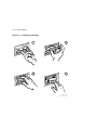
4.3 Avoiding Basic Problems
Follow these guidelines when operating the Tx867 subsystem to avoid
basic problems:
•
Use CompacTape III cartridges.
•
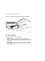
Check the tape leader in the cartridge by lifting the cartridge latch
that opens the door to expose the leader. Be sure the leader is in the
same position as the one shown in Figure 4–1.
CAUTION
Do not touch the exposed magnetic tape. If the tape leader is
not in the correct position, use a new cartridge.
•
Be sure that the receiver is fully closed and the current slot indicator
is on for the starting cartridge.
•
Be sure that no slots in the magazine are empty between the starting
cartridge and the expected completion cartridge.
NOTE
The Tx867 subsystem unloads and loads the next cartridge when
the subsystem receives a DISMOUNT command from the system.
4–4 Error Conditions and Problem Resolutions
Figure 4–1 Opening the Cartridge Door to Check the Tape Leader
CARTRIDGE
LEADER
DOOR LOCK
(RELEASE BY LIFTING
DOOR LOCK WITH THUMB)
SHR-0002-86
SHR_X1027_89_CPG
4.4 Error Conditions
Error indications fall into two main categories:
•
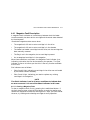
Magazine Fault — In most cases, this fault is an operatorcorrectable condition, and is indicated by the Magazine Fault indicator
being on. If you cannot resolve the fault, call your Digital Services
representative.
•
Loader Fault — This is a condition that most likely requires service
from a Digital Services representative. It is indicated by the Loader
Fault indicator being on.
Error Conditions and Problem Resolutions 4–5
4.4.1 Magazine Fault Description
A magazine fault indicates an inconsistency between what the loader
transfer assembly has done with a cartridge and the actual state detected
by the subsystem.
Inconsistent magazine status occurs when:
•
The magazine is full and an extra cartridge is in the drive
•
The magazine is full and an extra cartridge is in the elevator
•
The loader has loaded a cartridge into the drive, but the cartridge has
been manually removed
•
The flag is set in the magazine, but no cartridge is present
•
An unrecognized cartridge is in the magazine
When these conditions are present, the Magazine Fault indicator is on,
indicating a situation that can be corrected by the operator. The Eject
indicator is also on to inform you that this is the only function available
at this time.
Slot indicators are as follows:
•
Slots 6 and 0 light, indicating a cartridge in the drive was not loaded
by the loader transfer assembly.
•
Slots 5 and 0 light, indicating you need to replace any missing
cartridges in the magazine.
NOTE
The Slot 0 indicator is on in all error conditions to indicate that
an error occurred. It is not a Slot Select indicator in this case.
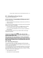
4.4.1.1 Clearing a Magazine Fault
To clear a magazine fault, first try pressing the Load/Unload button. If
the fault does not clear, press the Eject button to open the receiver and
remove the magazine to locate the cartridge error. After you have cleared
the error, try loading and unloading cartridges to verify operation.
4–6 Error Conditions and Problem Resolutions
4.4.2 Loader Fault Description
A loader fault indicates that the Tx867 subsystem has detected a fatal
error in either the loader transfer assembly or the tape drive. In the case
of some loader transfer assembly errors, the subsystem retries the error
three times before indicating failure. All loader faults generate an error
log as well as light the Loader Fault indicator and an associated subcode.
The Loader Fault indicator indicates errors in the loader transfer
assembly, controller module, and drive. The suspected location of a
fault is indicated by the following slot indicators:
•
Slots 4 and 0 light, indicating a controller module fault.
•
Slots 5 and 0 light, indicating a loader transfer assembly fault.
•
Slots 6 and 0 light, indicating a drive fault.
NOTE
Error indicators do not blink. During hardware failures, the
controller module determines action.
4.4.2.1 Clearing a Loader Fault
When a loader fault occurs, the Load/Unload and Eject indicators are on.
When you press the Load/Unload button, the Tx867 subsystem attempts
to clear the error. When you press the Eject button, the receiver opens to
let you access the magazine.
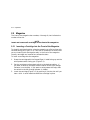
4.5 Power Problems
If the Power On indicator is not on, or your system does not recognize the
Tx867 subsystem:
•
Verify that the subsystem is pushed completely into the enclosure.
(Power to the loader transfer assembly is disabled when it slides
forward.)
•
Verify with your system manager that the subsystem configuration is
correct.
•
Call your Digital Services representative.
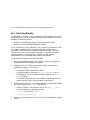
5
Head Cleaning
The Tx867 magazine tape subsystem uses the CleaningTape III cartridge
(Figure 5–1) for cleaning the read/write head in the tape drive.
The CleaningTape III cartridge is a yellow plastic cartridge containing
1200 feet of 1/2-inch, magnetic particle (MP) cleaning tape. You can use
the CleaningTape III cartridge approximately 20 times before it expires.
5–1
5–2 Head Cleaning
Figure 5–1 CleaningTape III Cartridge
TM
Cl
e
in
an
gT
a
III
pe
SHR_X1020E_89
Head Cleaning 5–3
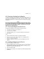
You can use two procedures to clean the read/write head:
1. Access the tape drive and load the CleaningTape III cartridge directly
into the drive (Section 5.1).
2. Insert the CleaningTape III cartridge into the magazine, where it then
loads into the drive (Section 5.2).
NOTES
Perform the head cleaning procedure only when the orange Use
Cleaning Tape (Figures 5–2 and 5–3) indicator is on.
If the Loader Fault indicator is on, clear the fault before
proceding with head cleaning.
5–4 Head Cleaning
Figure 5–2 Drive Front Panel
ORANGE
ORANGE
YELLOW
GREEN
t
ad
gh
Lo
Li
o
T
t
ai his
t
W
n
pe
O dle pe
a
an t T
H
r
se his
t
In
se
lo e
C dl
an
H
R
d
oa
n
nl
to
U
ut t
o
B gh
T
i
ss L
re
P t
is
ai
th
W
n
pe
pe
O dle Ta
an ve
o
em
H
se
U
ed
g
e
n
ct
in
at dle
ni
te te
e
e a pe per an
ri ro
ap Us Cle Ta
W P
O H
T
Text is 8pt on 8pt
Rt,z,-45
TK85 is TI med (ti) 12pt
U
nl
oa
d
CARTRIDGE INSERT/RELEASE HANDLE
SHR-X0056H-91
Head Cleaning 5–5
Figure 5–3 Tx867 Operator Control Panel
O PERAT O R CO NT RO L PANEL
Eject
Load/Unload
MOD E S E LE C T K E Y
BUTTON
AND
INDICATOR
AREA
Slot Select
OCP
DISABLED
0
AUTOMATIC
MODE
Power On
OCP LABEL
CURRENT
SLOT
INDICATORS
0-6
Write
Protected
Tape In Use
1
MANUAL
MODE
Use
Cleaning Tape
SERVICE
MODE
Magazine
Fault
Loader Fault
2
Eject
3
DSSI NODE
ID LABEL
(TF867 ONLY)
Load/Unload
Slot Select
0
Power On
Write
Protected
Write Protect
Load Fault
1
Tape In Use
Use
Cleaning Tape
4
Magazine
Fault
Loader Fault
2
3
5
4
5
6
6
40% REDUCTION
SHR_X1025E_91
5–6 Head Cleaning
5.1 Accessing the Tape Drive
Unless otherwise instructed by a Digital Services representative, open the
Tx867 subsystem to access the tape drive for head cleaning only.
To access the tape drive:
1. Be sure that all Tx867 subsystem operations are stopped.
2. Ensure that the Eject indicator is on (Figure 5–3).
3. Set the Mode Select key to Service mode (Figure 5–3).
4. Press the Eject button and remove the magazine, if present.
5. Pull the Tx867 subsystem out of the storage array and toward you by
placing your hand under the top of the Tx867 subsystem’s front bezel
(Figure 5–4).
WARNING
If, after pulling the subsystem forward, the Power On
indicator does not turn off, do not attempt the head cleaning
procedure.
6. Lift the loader open latch (Figure 5–5) (to the right of the unit).
7. Move the loader transfer assembly to the left, taking care not to hit
the storage array.
You now have access to the drive’s cartridge entrance (Figure 5–2).
Head Cleaning 5–7
Figure 5–4 Sliding the Tx867 Subsystem Toward You
SF
20
0
FIRST
MECHANICAL
STOP
0
1
2
3
0
4
1
5
2
6
3
4
5
6
CXO-2461B
SHR_X1106B_89
5–8 Head Cleaning
Figure 5–5 Loader Open Latch
LOADER OPEN LATCH
SHR-0007-90
SHR-X0140-90-CPG
Head Cleaning 5–9
5.1.1 Loading the CleaningTape III Cartridge into the Drive
Be sure to use a CleaningTape III cartridge. Instructions for loading the
CleaningTape III cartridge follow:
1. Pull the handle to the open position when the green indicator steadily
lights (Figure 5–6).
2. Load the cartridge.
3. Push the handle closed. The green indicator turns off and the yellow
Tape In Use indicator begins to flash, indicating the tape is loading.
When the cleaning process is finished, a beep sounds, indicating that you
can unload the CleaningTape III cartridge.
NOTE
If the Use Cleaning Tape indicator remains on, the cleaning cycle
was not successful due to an expired cartridge. Replace the
cleaning cartridge, and repeat the cleaning process.
If a particular cartridge causes the Use Cleaning Tape indicator
to turn on frequently, it is suggested this cartridge be backed up
on another, and then discarded. A damaged cartridge may cause
unnecessary use of the CleaningTape III.
5.1.2 Securing the Tx867 Magazine Tape Subsystem
After cleaning the head, secure the Tx867 subsystem as follows:
1. Close the loader transfer assembly.
2. Press the Tx867 loader open latch to secure the Tx867 subsystem
(Figure 5–5).
3. Push the Tx867 subsystem back into the storage array.
4. Be sure that the Power On indicator is on.
5. Set the Mode Select key to a position other than Service mode.
5–10 Head Cleaning
Figure 5–6 Loading the Cartridge
1
2
3
4
SHR-0256-87
SHR_X1093_89_CPG
Head Cleaning 5–11
5.2 Inserting the CleaningTape III Cartridge into the
Magazine
CAUTION
If you choose to use this cleaning procedure, you must return
the CompacTape III cartridges to their original slots, and remove
the cleaning cartridge from the magazine after the cleaning
procedure is done.
To clean the read/write head by inserting the CleaningTape III into the
magazine rather than the drive, use the following steps (Figure 5–3):
1. Press the Load/Unload button to remove any cartridge that may be in
the drive, and to return the cartridge to the magazine.
2. Press the Eject button to open the receiver and remove the magazine.
3. Insert the CleaningTape III cartridge into the first slot of the
magazine.
4. Insert the magazine into the receiver; close the receiver.
5. Press the Load/Unload button to load the cleaning cartridge into the
drive.
Once the cleaning cartridge is loaded, the drive begins the head
cleaning procedure. When the cleaning procedure is complete, the
cleaning cartridge automatically returns to the magazine.
6. Press the Eject button to remove the magazine.
7. Remove the cleaning cartridge from the magazine and replace the
CompacTape III cartridge in the magazine.
A
VMS Operating System Commands
The Tx867 magazine tape subsystem uses most of the standard magnetic
tape commands that can be invoked under VMS operating system version
5.4-2 or later.
This appendix is a reference only; it does not include all the details that
may be involved in using VMS commands.
For more information about VMS commands and command files, see
the VAX/VMS Guide to Using Command Procedures (AA–H782B–TE),
VAX/VMS Command Language User’s Guide (AA–DO23C–TE), or the
VMS System Manager’s Manual (AA–LA00B–TE).
A.1 Tape Device Specific Commands
Use the following commands to operate the Tx867 magazine tape
subsystem:
•
ALLOCATE
•
BACKUP
MOUNT/FOREIGN
BACKUP
DISMOUNT
•
COPY
MOUNT
COPY
DISMOUNT
INITIALIZE
A–1
A–2 VMS Operating System Commands
A.1.1 ALLOCATE Command
The ALLOCATE command provides exclusive access to a device and
optionally establishes a logical name for that device. Once you have
allocated a device, other users cannot access that device until you
explicitly DEALLOCATE it, or until you log out. Use the following format
to allocate the Tx867 subsystem:
$ ALLOCATE device name: [logical name]
For example, to allocate the Tx867 subsystem for your use and assign it
to the logical name TAPE1, do the following:
$ ALLOCATE MIA0:TAPE1
The Tx867 subsystem’s physical device name is assigned by your system
manager after it is installed.
A.1.2 DEALLOCATE Command
The DEALLOCATE command cancels the exclusive access you assign to
a device with the ALLOCATE command.
$ DEALLOCATE device name: [logical name]
A.1.3 BACKUP Command
The BACKUP command provides protection against file volume
corruption by creating functionally equivalent backup copies.
Use the following format to back up a file:
$ BACKUP/NOCRC/GROUP=0/BLOCK=65534/label=[volume label]
filename.ext [device-name or logical name]:filename.bck
In addition to backing up single files, you can back up lists of files and
entire volumes.
VMS Operating System Commands A–3
NOTE
By selecting the /NOCRC and /GROUP=0 qualifiers and a large
block size with the /BLOCK qualifier (65534 is the largest possible
block size), you can achieve better performance from the Tx867
subsystem. The previous command line excludes the use of
the host-available CRC error detection/correction capability,
and depends on the embedded error checking and correction
capabilities of the Tx867 subsystem. Tx867 error correction
capabilities relate specifically to the Tx867 subsystem—not to
the entire system.
Use of the /NOCRC qualifier requires a systems management
decision relative to the incremental difference in data integrity
versus a performance tradeoff. In most cases, Tx867 internal error
detection and correction capabilities are sufficient to ensure data
integrity and recovery. The host-level CRC provides another level
of error detection and correction, which may be important under
some conditions.
Refer to your system manuals before deciding on qualifiers for use with
the BACKUP command. For detailed information about BACKUP and
other VMS tape commands, see the VAX/VMS Backup Utility Reference
Manual (AA–Z407B–TE).
A.1.4 MOUNT Command
The MOUNT commands lets you make a magnetic tape volume available
for processing. Note that it loads the tape with the protection set
according to the write-protect switch on the cartridge.
Use the following format to mount a tape with the Tx867 subsystem:
$ MOUNT/FOREIGN [device name] [volume label] [logical name]
As an example, to make TAPE1 available for processing, type the
following:
$ MOUNT/FOREIGN MIA0
The console displays a message:
TAPE1 MOUNTED ON MIA0:
Note that you must use the /FOREIGN qualifier when you are performing
BACKUP commands. Do not use it when you are performing COPY
commands.
A–4 VMS Operating System Commands
NOTE
For improved performance, you can also use the following
command:
$ MOUNT/CACHE=TAPE_DATA
For more information, see the VAX/VMS Mount Utility Reference Manual
(AA–Z424A–TE).
A.1.5 COPY Command
Use the COPY command, with the Tx867 subsystem, to copy files from
cassette tape.
In the following example, the MOUNT command requests that the volume
labeled GMB001 be mounted on the tape drive at MIA0 and assigns the
logical name TAPE1.
The COPY command uses the logical name TAPE1 for the input file
specification. All files on MIA0 are copied to the current default disk and
directory. The files keep their original file names and file types.
$ MOUNT MIA0: GMB001 TAPE1:
$ COPY TAPE1:*.* *.*
NOTE
Using the COPY command to move multiple files may not achieve
optimum performance. Check with your system manager for more
information.
A.1.6 DISMOUNT Command
The DISMOUNT command cancels the MOUNT command, makes the
unit unavailable for processing, and rewinds the tape.
To eject a tape cassette from the tape drive, you must rewind and unload
the tape. Use the following format:
$ DISMOUNT logical name or device name:
To rewind to the beginning of the tape (BOT) without unloading it, use
the following format:
$ DISMOUNT/NOUNLOAD logical name or device name:
VMS Operating System Commands A–5
A.1.7 INITIALIZE Command
CAUTION
Be sure that you are using a scratch tape before initializing;
otherwise, any existing data on the tape will be destroyed.
Use the INITIALIZE command to specify the device name, and write
a volume name to the magnetic tape volume loaded into the TF86
subsystem. Note that the tape must be write-enabled for the initializing
operation.
Use the following format:
$ INITIALIZE device name: [volume label]
As an example, to initialize the device TAPE1 and assign the volume
name GMB001, type the following:
$ INITIALIZE TAPE1: GMB001
For detailed information regarding volume names and magnetic tape
operations, see the Guide to VAX/VMS Disk and Magnetic Tape
Operations (AA–M539A–TE).
B
Using the TZ867 Subsystem with the
ULTRIX Operating System
This appendix is intended for those using the TZ867 tape subsystem with
the ULTRIX operating system.
This section includes:
•
Adding the TZ867 subsystem to your ULTRIX system
•
Tips on getting maximum capacity and performance
•
Using the TZ867 subsystem for unattended backups
•
Using various ULTRIX commands to save information on the TZ867
subsystem
B.1 Adding the TZ867 to the ULTRIX System
Before connecting the TZ867 subsystem to the SCSI bus:
1. Locate the SCSI ID switches at the rear of the TZ867 subsystem.
2. Ensure the SCSI ID (target ID) number for the TZ867 is unique. The
recommended ID is 5. Use SCSI ID 5 only if no other device on the
bus has SCSI ID 5.
3. Ensure all other devices on the SCSI bus have unique SCSI IDs.
B–1
B–2 Using the TZ867 Subsystem with the ULTRIX Operating System
B.1.1 Connecting the TZ867 to ULTRIX
To connect the TZ867 subsystem to the ULTRIX system:
1. Physically connect the TZ867 cable(s) to the ULTRIX system.
2. Ensure an entry for the TZ867 subsystem is specified in the ULTRIX
system configuration file. If you have to modify your configuration file
by adding an entry, then you must build a new kernel and reboot the
system. This is explained in Section B.1.3 and Section B.1.4.
3. Create logical device names for your TZ867 subsystem, explained in
Section B.1.5.
B.1.2 Checking the ULTRIX System Configuration File
Locate the ULTRIX system’s configuration file. It should be in the
/usr/sys/conf directory under the mips or VAX system subdirectory.
The configuration file name is the same as the system name and must
contain an entry for the TZ867 subsystem.
If...
Then...
An entry does not exist,
You need to create an entry in the
configuration file.
An entry already exists,
You do not need to change the configuration
file.
B.1.3 Creating an Entry
An entry has the following format:
tape name at controller device#
An example entry for Bus 0, SCSI ID 5:
tape tz5 at sii0 drive 5
To create an entry in the configuration file:
1. Refer to Table B–1 to determine the name according to your SCSI
target ID and your bus number. Usually, users have one bus, Bus 0.
Find the name, listed under the Bus 0 or Bus 1 columns.
For example: The name for SCSI Target ID 5, Bus 0 is tz5.
Using the TZ867 Subsystem with the ULTRIX Operating System B–3
Table B–1 Determining the Tape Name
SCSI Target ID
Bus 0
Bus 1
0
tz0
tz8
1
tz1
tz9
2
tz2
tz10
3
tz3
tz11
4
tz4
tz12
5
tz5
tz13
6
tz6
tz14
7
tz7
tz15
2. Determine the name of the controller to which the TZ867 subsystem
is connected.
3. Include the word tape, name, controller, and the device# in the entry.
B.1.4 Building the Kernel, Rebooting the System
If you added an entry to your configuration file, you must rebuild the
kernel and reboot the system. Be sure to save the original kernel before
rebooting the system.
For example:
$
$
$
$
/etc/doconfig
mv /vmunix /vmunix.old
mv new_kernel_name /vmunix
/etc/shutdown -r now
(this creates a new kernel)
(save the old kernel)
(move the new kernel to the root directory)
(reboot the system)
B.1.5 Creating Logical Device Names for the TZ867
Subsystem
Use the MAKEDEV command located in the /dev directory to create
logical device names.
For example:
$ cd /dev
$ MAKEDEV tz5
B–4 Using the TZ867 Subsystem with the ULTRIX Operating System
leads to some or all of the following logical device names:
/dev/nrmt0l
/dev/nrmt0h
/dev/rmt0l
/dev/rmt0h
/dev/rmt0m
/dev/nrmt0m
/dev/rmt0a
/dev/nrmt0a
•
mt (in the middle of the logical name) means magnetic tape device.
•
nr means no rewind when the utility completes. Use the no rewind
option when more than one operation is being performed to the same
tape.
•
r means rewind when the utility completes.
•
0 is the logical unit number.
•
l means low density.
•
h means high density.
•
m means medium density.
•
a means auxiliary density.
NOTE
Since the TZ867 is a high density tape subsystem, be sure to use
the logical device names including h. The only exception is if
modifications are made to allow selection of TK85 density for
writing via the low density device entry (Section B.4).
B.2 Getting Maximum Capacity and Performance
The TZ867 subsystem:
•
Can store up to 6.0 GB of data per tape cartridge for a total subsystem
capacity of 42.0 GB
•
Run at peak streaming rates of 800 KB/s
This section explains how to maximize the functions of the TZ867
subsystem.
Using the TZ867 Subsystem with the ULTRIX Operating System B–5
B.2.1 Getting Maximum Storage Capacity
To get maximum storage capacity:
Use block sizes that are integral multiples of 4,096 bytes, such as 4k, 8k,
12k, 16k, and so forth. It is recommended you use larger block sizes of
16k, 24k, or 32k, which:
•
Allow more efficient data processing by the host and on the SCSI bus
•
Maximize capacity
Some utilities and commands default to using block sizes that cause lower
capacity and I/O rates. For example:
•
If you use a 512 byte block size (this is the dd command’s default),
you will be able to fit only about 320 MB of data on the tape.
•
If you use the recommended block sizes, this tape has a potential of
6.0 GB capacity.
Most utilities used for tape I/O let you select the block size through
command line switches.
NOTE
If you are not using ULTRIX V4.2a or later, with the latest
Common Access Method (CAM) software kit installed, you have a
tape file length limit of 2.1 GB.
With striping or disk array techniques or when running the tar
command to backup multiple file systems, you need to note the 2.1
GB limit. Plan backups so that a tar or dump set does not exceed
the 2.1 GB limit. However, you can store multiple save sets on the
same cartridge.
B.2.2 Maximizing Performance
To handle bursts of data, the TZ867 subsystem has 512 KB of cache
memory. This minimizes repositioning and keeps I/O rates as high as the
host can handle, up to 800 KB/s.
If a non-optimal block size is used, the possible average I/O rate is limited.
The recommended block sizes are: 16k, 24k, or 32k. You can use larger
block sizes of 36k, 40k, and so forth, but performance increase is unlikely.
Other factors that can limit performance:
•
Data fragmentation on disks
•
Overusing the I/O channel bandwidth
B–6 Using the TZ867 Subsystem with the ULTRIX Operating System
•
Processing speed and host CPU loads
•
Memory size
B.3 Doing Unattended Backups
This section explains how to use the TZ867 subsystem as an unattended
backup device.
Unattended backups require some extra planning, since the dump and
restore utilities do not support automatic cycling of tape cartridges at
this time on the TZ867 subsystem. Therefore, the backups must complete
before reaching the end of the cartridge to avoid having the utility unload
the cartridge and require user input to continue.
When the utility you are using completes, the command, mt, with the
offline option, can be used to cause the loaded cartridge to unload and
the next cartridge to load. Then the tar or dump utility or whatever
utility you are using can be used to backup the next set of files to be
saved. This can be automated by writing a shell script.
To do an unload operation:
1. Position the Mode Select key switch located on the TZ867 subsystem
front panel to the Automatic mode or locked position. This enables
the automatic loading and unloading function.
2. Issue the mt offline command.
B.3.0.1 Developing Unattended Backup Shell Scripts
To develop a shell script for doing unattended backups onto a TZ867
subsystem:
1. Choose a backup utility that can control the blocking factor on tape.
This will help you fully use the capacity and I/O rates of the TZ867
subsystem.
2. Plan what file systems are to be saved on each tape cartridge. Ensure
that the total amount of data to be written on each cartridge is less
than 6.0 GB.
3. Use mt offline commands at the appropriate points to cause
automatic cycling to the next cartridge as needed.
4. Test the script to verify it operates as intended.
Using the TZ867 Subsystem with the ULTRIX Operating System B–7
The following is an example of a script:
#
#************************************************************************
#
# Nightly backup script for system DEVSYS
#
# Note: Setup loader to have cartridge #0 loaded before starting
#
#************************************************************************
#
# Cartridge 0: backup user directories
#
mt -f /dev/rmt2h rewind
tar -b 32k -cf /dev/rmt2h /usr/users/gimli
tar -b 32k -rf /dev/nrmt2h /usr/users/legolas
tar -b 32k -rf /dev/nrmt2h /usr/users/pippin
tar -b 32k -rf /dev/nrmt2h /usr/users/merry
mt -f /dev/rmt2h offline
#
# Cartridge 1: backup project disk A
#
dd if=/dev/rz1a of=/dev/rmt2h bs=32768
mt -f /dev/rmt2h offline
#
# Cartridge 2: backup project disk B
#
dd if=/dev/rz2a of=/dev/rmt2h bs=32768
mt -f /dev/rmt2h offline
#
# Cartridge 3: backup some filesystems
#
dump 0dsf 42500 57600 /dev/nrmt2h /dev/rrz0a
dump 0dsf 42500 57600 /dev/nrmt2h /dev/rrz0b
mt -f /dev/rmt2h offline
#
B–8 Using the TZ867 Subsystem with the ULTRIX Operating System
B.4 Selecting Density
As explained in Chapter 1, density selection for write operations is not
supported by ULTRIX at the time of this printing. However, if the CAM
software is installed, you can:
•
Modify the /sys/data/cam_data.c file to recognize the TZ867
•
Assign the write densities selected by the host
The TK85 density is SEQ_42500_BPI (17h) and the TK86 density is 18h
(no symbol is defined for this new media format). Changing the
cam_data.c file should only be done by experienced users. You must
rebuild the kernel to incorporate the changes. (See the configuration
guidelines earlier in this appendix. Check the CAM software
documentation for information about adding new devices.)
To allow density selection from the shell level:
1. Edit the /sys/data/cam_data.c file. Ensure a copy of the original is
preserved and can be restored if necessary.
2. Make a copy of the TZ857’s density table (tz857_dens) found in
/sys/data/cam_data.c. In this copy:
•
Change the TZ857 references to TZ867
•
Change the density code from SEQ_42500_BPI to 0x18 for all
the subentries in the new density table, except for the minor 00
(rmtxl) subentry.
This allows device rmtxl entries to select TK85 format and the
others (rmtxm, rmtxh, rmtxa) to select TK86 format.
3. Make a copy of the entry in the device descriptor information table for
the TZ857 (search for DEV_TZ857) and change:
•
TZ857 to TZ867 in the comment and in the "DEC_ __ __TZ857"
string (underscores indicate five spaces)
•
DEV_TZ857 to the string: "TZ867"
•
&tz857_dens to &tz867_dens
4. Save the current kernel, build a new kernel, and reboot with the new
kernel.
Using the TZ867 Subsystem with the ULTRIX Operating System B–9
B.5 Using ULTRIX Tape Commands
This section describes ULTRIX commands used to operate the TZ867
subsystem.
The TZ867 subsystem uses standard magnetic tape commands to do
backup and restore operations. The tar and dump/restore commands
are used most often.
B.5.1 Using the tar Command
The tar command, which operates on files and directories, writes and
reads tapes. The tar utility uses the specified block size or defaults to
10k byte block sizes. The default block size results in a 16% decrease of
maximum capacity and I/O rates.
Table B–2 lists the options you can use with the tar command.
Table B–2 Common tar Options
Option
b
c
f
r
t
u
v
x
Meaning
Block size in bytes (n)
Block size in kilobytes (nk)
nb = n x 512 bytes in a block
Create tape, writes from beginning
Tape device argument to follow
Append to the end of the tape
Table of contents of tape
Backup all new or modified files from last backup
Verbose
Extract from tape (read)
The following examples show command lines with the tar command to:
•
Write a file to tape:
$ tar -cf /dev/rmt0h
•
filename
-b 64k
Read a file from tape to your current directory:
$ tar -fx /dev/rmt1h
filename
B–10 Using the TZ867 Subsystem with the ULTRIX Operating System
B.5.2 Using the dump Command
To use the dump command, you need system privileges. This command
lets you write an entire file system to tape. Ensure that the current
directory is not within the file system being backed up, except when
backing up from the root directory.
The dump command uses 10k byte block sizes. A 16% reduction in
capacity and I/O rates can result from using these block sizes.
Table B–3 lists the options you can use with the dump command.
Table B–3 Common dump Options
Option
d
f
n
s
u
0-9
Meaning
Recommended Value
Tape density in bits per inch
Tape device
Notify all privileged accounts, the
status of dump
Size of tape in feet
Update the /etc/dumpdates file with
the date
Dump level
42500
57600
The following examples show command lines with the dump command:
$ dump 0dsf 42500 57600 /dev/rmt0h /dev/rrz1a
$ dump unsf 42500 57600 /dev/rmt0h /usr/users
Dump level 0 is the highest and dumps the whole file system.
Dump level 9 is the lowest. All files, modified since the last dump of the
same or lower dump level, are dumped.
B.5.3 Using the restore Command
The restore command reads a tape that is backed up with the dump
command. The restore command can read a file, a directory, or the entire
tape.
The restore command uses 10k byte block sizes. A 16% reduction in
capacity and I/O rates can result from using these block sizes.
Using the TZ867 Subsystem with the ULTRIX Operating System B–11
Table B–4 lists the options you can use with the restore command.
Table B–4 Common restore Options
Option
f
r
i
v
x
Meaning
Tape device
Read everything from tape
Interactive
Verbose
Extract
The following example shows a command line with the restore command:
$ restore -xvf filename
B.5.4 Using the dd Command
Use the dd command to perform a device-to-device copy. The copy is done
by file or by image, depending on the specification of the input or output
device files.
Disks have two types of device files, image and block:
•
If the disk image file (/dev/rrxxx) is used, performance is faster.
•
If the disk block file (/dev/rxxx) is used, it is easier to retrieve a single
file later.
The dd command uses the specified block size, or if none is given, a
default of 512 bytes. An 87% reduction in capacity and performance can
result from using the default block size. It is important to specify a more
optimal block size.
Table B–5 lists the options you can use with the dd command.
Table B–5 Common dd Options
Option
if
of
bs
ibs
obs
Meaning
Recommended Value
Input file
Output file
Input and output block size (bytes)
Input block size (bytes)
Output block size (bytes)
32768
32768 for tape
32768 for tape
B–12 Using the TZ867 Subsystem with the ULTRIX Operating System
The following examples show command lines with the
dd command to:
•
Write to tape with the block device file:
$ dd if=/dev/rz1a of=/dev/rmt1h bs=32768
•
Write to tape with the image device file:
$ dd if=/dev/rrz1a of=/dev/rmt1h bs=32768
•
Read a tape:
$ dd if=/dev/rmt1h of=/dev/rz1a ibs=32768
B.5.5 Using the ltf Command
Use the ltf command to write and read ANSI tapes. This command
operates on files and directories and uses the specified block size.
Otherwise, the command defaults to 2,048 byte blocks, resulting in a
50% decrease of capacity and I/O rates.
Table B–6 lists the options you can use with the ltf command.
Table B–6 Common ltf Options
Option
B
c
f
u
t
v
x
Meaning
Specify a block size to use
Create tape, writes from beginning
Tape device argument to follow
Backup all new or modified files from last backup
Table of contents of tape
Verbose
Extract from tape (read)
The following examples show command lines with the ltf command to:
•
Write a file to tape:
$ ltf -cf /dev/rmt0h
•
filename
-B 16k
Read a file from tape to your current directory:
$ ltf -fx /dev/rmt1h
filename
Using the TZ867 Subsystem with the ULTRIX Operating System B–13
B.5.6 Using the mt Command
The mt (magnetic tape) command allows you to give certain commands to
the tape drive.
Table B–7 lists the options you can use with the mt command.
Table B–7 Common mt Options
Option
Meaning
eof
bsf
bsr
fsf
fsr
offline
rewind
status
Write file mark(s)
Backward space file(s)
Backward space record(s)
Forward space file(s)
Forward space record(s)
Unload the tape
Rewind to the beginning of medium
Obtain information from the drive
The following examples show command lines with the
mt command to:
•
Get the status of a drive:
$ mt -f /dev/rmt0h status
•
Rewind the default drive:
$ mt rewind
•
Write two file marks to the default drive:
$ mt eof 2
B.5.7 Using the cpio Command
The cpio command allows you to save files and directories on tape and
other media and retrieve these files.
Table B–8 lists the options you can use with the cpio command.
B–14 Using the TZ867 Subsystem with the ULTRIX Operating System
Table B–8 Common cpio Options
Option
c
d
i
o
t
v
Meaning
Write or read header information in ASCII character form
Create directories as needed
Copy in
Copy out
Table of contents of tape
Verbose
The following examples show command lines with the cpio command to:
•
Write to tape all files and subdirectories from your current directory:
$ find . -print | cpio
•
/dev/rmt0h
List all files and subdirectories that are on the tape:
$ cpio -ictv <
•
-ocv >
/dev/rmt0h
Retrieve all files and subdirectories from the tape:
$ cpio -icdv < /dev/rmt0h
•
Retrieve selective files from the tape:
$ cpio -icv <
’filename’ < /dev/rmt0h
C
Service Offerings
Digital Equipment Corporation offers a range of flexible service plans.
C.1 On-Site Service
On-site service offers the convenience of service at your site and insurance
against unplanned repair bills. For a monthly fee, you receive personal
service from our service specialists. Within a few hours, the specialist is
dispatched to your site with equipment and parts to give you fast and
dependable maintenance.
C.2 BASIC Service
BASIC service offers full coverage from 8 a.m. to 5 p.m., Monday through
Friday. Options are available to extend your coverage to 12-, 16-, or 24hour periods, and to include Saturdays, Sundays, and holidays. Under
the BASIC service plan, all parts, materials, and labor are covered in full.
C.3 DECservice Plan
The DECservice plan offers a premium, on-site service for producing
committed response to remedial service requests made during contracted
hours of coverage. Remedial maintenance will be performed continuously
until the problem is resolved, which makes this service ideal for customers
requiring maximum service performance. Under the DECservice plan all
parts, materials, and labor are covered in full.
C–1
C–2 Service Offerings
C.4 Carry-In Service
Carry-in service offers fast, personalized response, and the ability to
plan your maintenance costs for a smaller monthly fee than on-site
service. When you bring your unit to one of 160 Digital SERVICenter
sites worldwide, factory-trained personnel repair your unit within 2 days.
This service is available on selected terminals and systems. Contact your
local unit. Digital SERVICenter sites are open during normal business
hours, Monday through Friday.
C.5 DECmailer Service
DECmailer service offers expert repair at a per use charge. This service
is designed for users who have the technical resources to troubleshoot,
identify, and isolate the module causing the problem. Mail the faulty
module to our Customer Returns Center where the module is repaired
and mailed back to you within 5 days.
C.6 Per Call Service
Per call service offers a maintenance program on a noncontractual,
time-and-materials-cost basis. It is appropriate for customers who have
to perform first-line maintenance, but may occasionally need in-depth
support from Digital Services.
Index
A
Adding the TZ867
ULTRIX system, B–1
ALLOCATE command, A–2
Automatic mode, 2–2
B
BACKUP command, A–2
Automatic mode, 2–2
Backup failures, 4–3
Backup unattended
ULTRIX, B–6
BOT (beginning of tape), A–4
Button operation
conditions for, 4–2
C
Cartridge
checking the tape leader, 4–3
inserting into magazine, 2–8
loading, 2–6
unloading, 2–7
write-protect switch, 2–8
Cartridge compatibility
read/write ability, 1–14
Cleaning procedure for read/write
head, 5–9
CleaningTape III cartridge, 5–1
inserting into magazine, 5–11
loading into drive, 5–9
CompacTape III cartridge, 1–13
Components, major, 1–10
controller module, 1–12
loader transfer assembly, 1–10
magazine, 1–12
rear chassis, 1–12
Components, major (cont’d)
TK86 tape drive, 1–12
Configuration file
ULTRIX, B–2
Configuration, of Tx867 subsystem
physical, 1–3
Connecting the TZ867
ULTRIX system, B–2
Controller fault description, 4–6
Controller module, 1–12
COPY command, A–4
D
Density selecting, ULTRIX, B–8
Density, selecting
TF867, 1–14
Diagnostic utilities protocol (DUP),
3–2
Diagnostics, local
accessing, 3–2
DIRECT utility, 3–3
DRVEXR program, 3–10
DRVTST utility, 3–10
FYDRIVER program, 3–3
HISTRY program, 3–4
LDRTST program, 3–11
PARAMS program, 3–5
programs, 3–1
utilities, 3–1
Digital Services
offerings, C–1
DIRECT utility, 3–3
DISMOUNT command, A–4
Documentation, related, 1–18
Drive
access for read/write head
cleaning, 5–6
cartridge entrance, 5–6
Index 1
2 Index
Drive fault description, 4–6
DRVEXR program, 3–10
DRVTST utility, 3–10
DSSI node ID label, 1–5
E
Eject button, 2–6
cartridge in drive, 2–7
no cartridge in drive, 2–7
unload function, 2–4
use of, 4–2
Eject indicator, 4–2
Entry, creating an
ULTRIX, B–2
Error conditions, 4–4
Error message
SET HOST/DUP command, 3–3
EXIT command, 3–9
F
FYDRIVER program, 3–3
H
Head cleaning procedure, 5–1
securing the subsystem, 5–9
HELP command, 3–6
HISTRY program, 3–4
I
INITIALIZE command, A–5
L
LDRTST program, 3–11
Loader fault description, 4–6
Loader open latch, 5–8
Loader reset, 4–6
Loader transfer assembly, 1–10
Load/Unload button, 2–6
reset, 4–6
reset function, 2–4
use of, 4–2
Load/Unload indicator, 4–2
Logical device names, creating
ULTRIX, B–3
M
Magazine, 1–12, 2–8
inserting cleaning tape, 5–11
removing from receiver, 2–11
restoration into receiver, 2–11
status of, 4–5
Magazine fault
clearing, 4–5
Manual mode, 2–2
Maximizing performance
ULTRIX, B–5
Maximum capacity and performance
ULTRIX, B–4
Maximum storage capacity
ULTRIX, B–5
Mode Select key
Automatic mode, 2–2
description, 2–2
Manual mode, 2–2
mode definitions, 2–2
OCP Disabled mode, 2–2
Service mode, 2–4
Modes of operation, 1–8
MOUNT command, A–3
O
OCP Disabled mode, 2–2
Operating modes, 2–2
Operating procedures, 2–1
Index 3
P
Parameters, TF867 subsystem
displaying, setting, saving, 3–6
list of, 3–5
PARAMS program, 3–5
EXIT command, 3–9
HELP command, 3–6
SET command, 3–8
SHOW /ALL command, 3–7
WRITE command, 3–9
POST, 2–1
Power problems, 4–6
Power-on, 2–1
Power-on self-test
status of OCP indicators, 2–1
Problem resolutions, 4–1
conditions to check, 4–2, 4–5, 4–6
reset, 4–6
R
Rebooting system
ULTRIX, B–3
Receiver, 2–11
Reset, 4–6
Load/Unload button, 2–4
S
Scripts, unattended backup
ULTRIX, B–6
Securing the Tx867 subsystem, 5–9
Service mode
unlocking the Tx867 subystem,
2–4
Service plans, C–1
SET command, 3–8
SET HOST/DUP command
accessing local programs, 3–2
error message, 3–3
SHOW /ALL command, 3–7
Slot Select button, 2–6
operation, 2–6
use of, 4–2
Slot Select indicator, 4–2
Specifications
TK86 tape drive, 1–17
Tx867 subsystem, 1–16
Supplies, 1–18
T
Tape leader, 4–3
TK86 tape drive, 1–12
U
ULTRIX, B–1
cpio command, B–13
dd command, B–11
density selecting, B–8
dump command, B–10
dump levels, B–10
ltf command, B–12
mt command, B–13
restore command, B–10
tar command, B–9
ULTRIX system tape commands,
B–9
Unattended backup
ULTRIX, B–6
Unattended backup scripts
ULTRIX, B–6
V
VMS operating system
commands, A–1
logical device name, A–4
physical device name, A–2
4 Index
W
WRITE command, 3–9
Write-protect switch, 2–8, A–3