1
MX SERIES MODULE DESCRIPTION
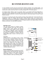
The Exeltech MX Series of inverters is a modular system which can be assembled in many combinations
to afford the user infinite flexibility. Options such as AC distribution, AC disconnect, metering, DC
disconnect, DC distribution, transfer switch and maintenance bypass switch are also available; (see
accessories).
The building blocks of the system are as follows:
1.) Power Module - A 1000 Watt slave power inverter. It requires drive signals from a Master Module or
Control Card as described below. This module is the backbone of the inverter system.
2.) Master Module - A 1000 Watt power inverter which contains all the electronics necessary to operate.
Requires an enclosure to provide connections to the battery and AC output. It can also operate up to 19
slave Power Modules. If this module is used, the system cannot be fully redundant.
All MX systems require either a master module or at least one control card.
3.) Control Card - Generates all the signals necessary to operate up to 20 Power Modules. The card itself
will not generate any AC output power nor does any power flow through it. This card can be
paralleled with another Control Card to generate a redundant set of control signals to form the basis of
a completely redundant inverter system.
All MX systems require either a master module or at least one control card.
4.) Alarm Card - Can be used in conjunction with a redundant or non redundant inverter to provide various
alarm output signals via LED's and alarm contact closures. Must be included in redundant systems to
detect failure of control card.
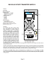
5.) Transfer Switch - Provides the same functions as the alarm card, plus provides a relay to transfer AC
power to the load, from either the inverter or the utility input. Use only with systems 7KW of or less.
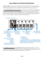
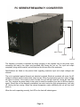
The above modules can be placed in the following enclosures; Installations can either be free standing
or in standard relay racks.
1.) 19" cage assembly - Compatible with a 19" relay rack. The smallest cage which can contain a
redundant system. Available in the following configurations:
19A - Basic configuration for a redundant system. Holds up to 4 Power Modules, 2 Control Cards and
either a Transfer Switch, System Monitor Card or an Alarm Card.
19B - Used as an expansion rack or may be used as an expandable, non redundant inverter, up to 5 KW.
This configuration will not accept X-fer Switch, alarm card or control cards.
2.) 23" cage assembly - Compatible with a 23" relay rack.
23A - Basic configuration for a redundant system. Holds up to 5 Power Modules, 2 Control Cards and
either a Static Transfer Switch, Transfer Switch, System Monitor II or an Alarm Card.
23B - Used as an expansion rack or may be used as an expandable, non redundant inverter, up to 6 KW.
This configuration will not accept X-fer Switch, alarm card or control cards.
3.) 7" cage assembly - for 1 or 2KW systems when redundancy is not required.
7C - Consists of 1 Transfer Switch and 1 Master Module.
This configuration will not accept an alarm card or control cards.
7B - Expandable up to 2KW. 1 Master Module and 1 Power Module.
This configuration will not accept X-fer switch, alarm card or control cards.
4). 9" cage assembly- for 1-3KW systems when redundancy is not required.
9C - Consists of Transfer Switch, 1 Master Module and 1 Power Module.
This configuration will not accept an alarm card or control cards.
9B - Expandable up to 3KW. 1 Master Module and 2 Power Modules.
This configuration will not accept X-fer Switch, alarm card or
control cards.
Page 2