1
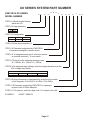
MX SERIES SYSTEM DESCRIPTION
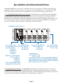
Figure II.
1 ea. Cage assembly
part # 1A (19" cage)
2A (23" cage)
MX
CONTROLMX 1000 Power Module
Overload
CARD
Load
On
1 ea. Control Card
part # L*(100 Vac)
C*(120 Vac)
E*(230 Vac)
Options:
1 ea. X-fer Switch
part # G (100 Vac)
S (120 Vac)
X (120 Vac)
Z (230 Vac)
1 ea. Alarm Card
part # H (100 Vac)
A (120 Vac)
B (120 Vac)
C (120 Vac)
F (230 Vac)
1 ea. Power Module
part # P (100 Vac)
P (120 Vac)
R (230 Vac)
3.)Expandable inverter system:This configuration can be used as an independent inverter system (figure
III), or to expand power levels of existing MX systems (see stacked systems). By using one master module,
a system may be expanded to include a X-fer switch and additional power modules(see figure IV). 1KW
inverters with a X-fer switch use the 7"or 9" (part # 7C, 9C) cage. 1KW, 2KW and 3KW inverters without
a X-fer switch use the 7" or 9" (part number 7B, 9B) cage assembly.
Figure III.
1 ea. Cage assembly
part # 1B (19" cage)
2B (23" cage)
7B (7" cage)
1 ea. Cage assembly 9B (9" cage)
part # 1A (19" cage) expansion rack
2A (23" cage) (see stacked
7C (7" cage)
systems)
9C (9" cage)
Options:
1 ea. X-fer Switch
part # G (100 Vac)
S (120 Vac)
X (120 Vac)
Z (230 Vac)
MX TRANSFER SWITCH
1 ea. Master Module1
part # Q* (100 Vac)
M* (120 Vac)
N* (230 Vac)
ON
MX 1000 Power Module
Overload
OFF
Load
MX 1000 Power Module
Overload
MX 1000 Power Module
Overload
MX 1000 Power Module
Overload
MX 1000 Power Module
Overload
MX 1000 Power Module
Overload
MX 1000 Power Module
Overload
Load
Load
Load
Load
Load
Load
On
On
On
On
On
On
Up to 5
Power Modules
1 ea. Master Module
part # Q* (100 Vac) part # P (100 Vac)
P (120 Vac)
M* (120 Vac)
R (230 Vac)
O* (230 Vac)
Figure IV.
1
INVERTER
DC
VOLTAGE
MAIN AC
BREAKER
ON
On
MODULE
FAIL
TEMP
LOAD
UTIL
UTIL
SOURCE
INV
OURCE
ERTER
OFF
IMARY
VERSE
UTIL
I
SELECT
INV
1 Alarm
card is not an option on this configuration
Page 4