1
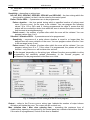
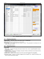
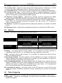
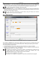
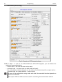
46 3.3.9 Programming SATEL Groups of partitions You can define up to 16 partition groups which will be controlled using the 80. ARMING, 81. DISARMING and 83. CLEARING ALARM type zones. The partition groups can be defined: using the keypad, in the service mode, by means of the GROUPS function (ZONES GROUPS). using the DLOADX program, in the ”Zones” window, "Arm/Disarm Groups" tab. 3.3.10 Zone testing Using the function available in the service mode menu in the keypad (ZONES TEST), you can test the zones. Information on violation or tamper of the zone is displayed and signaled by beeps in keypad (violation – 5 short beeps; tamper – 1 long beep; masking – 3 long beeps). Additionally, the function allows selection of a system output which will be used for signaling during the test (zone violation will activate the output for 0.4 second, tamper – for 1,6 seconds, masking – for 3 seconds). Violation/tamper/masking of the zone during the test will not trigger the response programmed for the control panel zone. Select a zone for testing from the list and press the or key. The output allocated for signaling will stop doing its present duty (if it was active, it will be disabled) until the zone test is completed (the key pressed). The output used for signaling is only remembered until exiting the TEST function. When the TEST function is re-started, the output must be selected again. If wireless sirens are used in the system and any output is selected for signaling, after selecting a zone for testing from the list and pressing the or key, in the wireless sirens the signaling will be unblock (which is normally blocked for the service mode duration). If the output selected for signaling controls the wireless siren, it should be borne in mind that the command to block/unblock signaling is sent out during polling. This results in a delay whose duration depends on the programmed response period. Also in case of the ASP-205 siren signaling is only triggered during the polling period. 4. Outputs The system supports the following outputs: hardwired – on the control panel electronics board and in expanders. The number of available hardwired outputs is determined by the control panel during identification procedure. wireless – after connecting the ACU-100 or ACU-250 controller. The number of available wireless outputs depends on the number of wireless devices registered in the system and is determined during the procedure of adding wireless devices. virtual – the outputs which do not exist physically, but can be used e.g. for execution of logical functions. Programming of the outputs is possible: using the keypad, in the service mode, by means of functions available in the OUTPUTS submenu; using the DLOADX program, in the "Outputs" window.