1
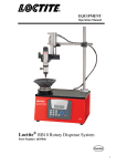
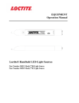
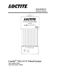
EQUIPMENT Operation Manual Loctite VA10 Micro Diaphragm Valve Part Number 1611449 Table of Contents 1 Description 3 2 Specifications 3 3 Unpacking and Inspection 3 4 Theory of Operation 4 5 Typical System Setup 5 6 Setup Instruction 5 7 Troubleshooting 6 8 Care and Maintenance 7 9 Accessories and Spare Parts 8 10 Exploded Diagram Parts List 9 13 Warranty 10 2 1 Description The Loctite® VA10 Micro Diaphragm Valve is a small normally closed dispense valve for dispensing low to medium viscosity adhesives. Its miniature size allows for multiple valve stacking in minimal space and higher dispensing frequency. A tamper resistance stroke control provides for high resolution stroke adjustment which results in consistent flow control and bubble free, no drip dispensing. The materials of construction ensure that the Loctite® VA10 Micro Diaphragm Valve is compatible with most adhesive products Features Bubble free, no drip dispensing Compact size and weight High resolution stroke adjustment Seal less design Fail safe –air to open, spring to close UHMW polyethylene diaphragm Fluid body material: 316 stainless steel Fitting –Barb, 316 stainless steel Tamper resistance stroke control 2 Specifications Size: Total weight: Fluid Body: Air Cylinder Body: Fluid inlet thread: Diaphragm: Pneumatic pressure required: Maximum fluid pressure: Mounting Hole: 3 2 5/8”length x ¾”dia. (66.5 mm x 19 mm) approx. 1.75 oz. (50 g) Type 316 stainless steel Type 303 stainless steel #10-32 UHMW polyethylene 70 to 90 psi (4.8 to 6.2 bars) 70 psi (4.8 bars) #8-32 Unpacking and Inspection Carefully unpack the Loctite® VA10 Micro Diaphragm Valve and examine the items contained in the carton. Inspect the unit for any damage that might have occurred in transit. If such damage has occurred, notify the carrier immediately. Claims for damage must be made by the consignee to the carrier and should be reported to the manufacturer. Items supplied Loctite® VA10 Micro Diaphragm Valve includes: Operating Manual Feed line: 7 ft. [2 m] Teflon line tubing, ¼”[6.35 mm] O.D. Air line: 7 ft. [2 m] Nylon tubing, 5/32”[4 mm] Dispense Tip sample kit Stroke Control Adjustment Key Inlet fitting: #10-32 Barb, 316 stainless steel 3 4 Theory of Operation The dispense valve is normally a closed, fail-safe, adjustable opening, diaphragm valve. Input air pressure of 70 to 90 psi (4.8 to 6.2 bars) forces the internal piston to move a pre-adjusted distance, normally 0.025" or less. A connecting rod pulls open the diaphragm seal, permitting the fluid to flow through the diaphragm chamber. Relieving the input air pressure allows the piston return spring to close the diaphragm, ensuring rapid “fail-safe”shutoff of fluid flow. The amount of fluid that flows through the valve is determined by: (1) length of time the valve is open, (2) fluid reservoir pressure, (3) output dispensing tip size, (4) diaphragm stroke, (5) fluid viscosity. For small deposits of low viscosity fluid, the diaphragm adjustment will be set at a short stroke but never less than 1/8 turn from closed. The diaphragm stroke control adjustment is made by using the tamper resist stroke control key and turning counterclockwise to open. To ensure consistent dispensing, the fluid reservoir pressure and the timed pulse must be constant. Reservoir air pressure is determined by the viscosity of the fluid and the amount of fluid to be dispensed. The dispense valves can be operated in any position without affecting flow. Vibration normally has no effect on performance. The valves can be moved in and out of dispense positions at high cycle speeds (such as a reciprocating device installed on a production line) without affecting dispensing performance. The unique design of the dispense valves provides extremely high cycle rates at unusually close operating tolerances. 5 Typical Setup 4 6 Setup Instructions 1. 2. 3. Connect the fluid reservoir feed line to valve fluid inlet fitting. Connect control air from valve to a valve controller or pneumatic source used to control the ON time of the valve. Connect an appropriate size dispense tip to the male luer and secure with retaining nut. Use small diameter tips, 20 to 25 gage, for low viscosity fluids. Use larger tips, 14 to 20 gage, for more viscous fluids. With a valve controller set up and connected to the valve, and a fluid reservoir connected, as shown on page 5, load fluid reservoir per Reservoir Operating Manual instructions. CAUTION: Always treat a pressurized reservoir with respect, and check air gauge to ensure pressure is at zero before opening. To ensure that all pressure is bled off, all Loctite® reservoirs have a pressure relief valve that should be activated before opening the tank. After filling, check to be certain the reservoir is sealed. NOTE: Do not over tighten the diaphragm or open the stroke adjustment knob (counterclockwise) more than two full turns. Turning out more than two full turns does not increase the flow capacity, and will reduce the closure spring tension. This situation could permit pressurized liquid to force open the diaphragm seal, resulting in continuous liquid flow. Before proceeding, check the following: 1. Insure all the connections are tight. 2. Set the reservoir pressure. For low viscosity fluids, start with a pressure of approximately 5 psi (0.3 bar). For higher viscosity, start at 10 to 20 psi (0.7 to 1.4 bar), increase or decrease as necessary. If solvents or other watery fluids are to be dispensed in very small amounts, specify a 0 to 15 psi (0 to 1.0 bar) precision regulator to control the reservoir pressure. 3. Set the diaphragm stroke. Start with no more than 1/2 turn open. The dispense valves are shipped with the stroke adjustment set at 1/2 turn open. 4. Set the valve control air pressure at a minimum of 70 psi (4.8 bar). 5. Actuate the valve long enough to fill the valve, start liquid flow and purge air from the dispensing tip. If a small tip is used, it may need to be removed from the valve during purging. Then fill the tip hub with fluid and install on the tip adapter so it is free of air. 6. Before setting the controller time, adjust the valve stroke control and reservoir pressure to provide proper flow from the tip. Excessive flow can cause bubbles. Use only enough reservoir pressure to achieve the proper flow. Avoid setups with tight stroke setting and high reservoir pressures. 7. Test the dispensed amount with a nominal time setting. If more or less fluid is required, increase or decrease the open time or reservoir air pressure. Questions regarding installation, operation, or safety should be addressed to Loctite Technical Information Department in Rocky Hill, Connecticut. Telephone: 1-800-LOCTITE (1-800-562-8483). 5 7 Troubleshooting Problem No liquid flow Possible Cause If valve operating pressure is to low, the valve will not open. Correction Increase air pressure to 70 psi (4.8 bars) minimum The reservoir pressure may not be high enough Increase pressure The dispense tip may be clogged. Replace tip The diaphragm stroke adjustment may be closed. If closed, open counterclockwise ½ turn Adhesive may have set-up in the valve body Clean the valve body Fluid drools after the valve closes, eventually stopping. Liquid drips at a steady rate after the valve closes. This is caused by air trapped in the outlet of the valve body, or the product has entrapped air. The air will expand after the valve closes, causing product to extrude until the air reaches atmospheric pressure. A steady drip can be caused by excessive reservoir pressure. Purge the valve by dispensing a steady flow of adhesive until clear of air bubbles. If a small tip is being used, remove the tip while purging to obtain sufficient flow to carry the air down through the tip adapter. Check reservoir pressure to ensure it is not above 70 psi (4.8 bar) Liquid flows out of the drain hole If the stroke adjustment is turned out more than two full turns, the closure spring tension will be reduced, allowing normal reservoir pressure to force the diaphragm open. If reservoir pressure and stroke adjustment are within limits, a steady drip indicates failure of the diaphragm to close fully due to particle build up and wear. Fluid leaking out of the drain hole indicates a ruptured diaphragm. Check to be sure the stroke adjustment knob is less than two turns out. Remove the valve body, inspect sealing surfaces on the diaphragm and valve body. Replace worn parts. Replace diaphragm in accordance with maintenance instructions 6 8 Care and Maintenance Loctite® VA10 Micro Diaphragm Valve is designed to provide continuous dispensing service. Dispense valves used in production need no special care. Normally, purging with appropriate flush material or solvent after use is sufficient for cleaning. Some materials, however, may cause a buildup on the valve head and diaphragm which will require a periodic, thorough cleaning by removing the valve fluid body. To Remove Valve Fluid Body Hold the valve air cylinder section securely using the wrench flat. Rotate the fluid body counterclockwise using another wrench. If the diaphragm remains inside the fluid body it can be pulled out using a #4-40 screw. The valve body can be cleaned with flushing solvent. The diaphragm can also be cleaned but do not use sharp probes because nicks and scratches on the sealing surface may affect the diaphragms ability to seal. Replacing the Diaphragm Insert pin into end of piston. Hold piston and thread diaphragm onto piston by hand. Once diaphragm is installed thread fluid body onto the air cylinder. Dispense Valves Flushing & Cleaning Procedure If the dispensing system (reservoir, dispense valve, etc) will not be used for one or more weeks, it is recommended that the feed line and dispense valve be flushed clean with the proper solvent. This procedure will describe the process. •Turn off the reservoir pressure and verify that pressure has been exhausted from the reservoir. •Remove the reservoir lid and remove the adhesive container. •Replace it with a container of Equipment Flushing Solvent (item # 12121). •Replace the reservoir lid and tighten all wing nuts so the lid is secure. •Adjust the air pressure regulator to 5 psi. •Place a beaker or similar container under the dispense valve. •Press the footswitch or manually depress the trigger on the valve and allow the Equipment Flushing Solvent to flow into the container. •Note: this may take a few moments (or minutes) depending upon the viscosity of the adhesive in the feed line. •While the solvent is flowing, be sure to open and close the dispense valve in order to simulate an “agitation” effect. 7 •This agitation allows the dispense valve to open and close while the solvent is being forced around the ball and seat assembly. •Continue this process of opening and closing the valve every 5 seconds for a total of two (2) minutes or until the solvent is clear. •Once you are satisfied that all adhesive has been removed from the feed line and dispense valve, shut off the air and remove the flushing solvent. •Re-install the reservoir lid and adjust the pressure regulator to approx 70 % of its maximum value. •Press the footswitch or manually depress the trigger on the valve and allow air to continually flow out of the dispense valve. •CAUTION: the vapors from the flushing solvent will be emitted and should be directed into a paper towel or similar cloth. If an exhaust hood or fume filtration system is available, it should be used. •Continue to dispense air for approx. 1 minute or until all solvent has been removed from the feed lines. •While the air is being forced thru the feed lines, lightly tap the feed line leading from the reservoir to the dispense valve. •Once you are confident that all of the remaining solvent has been purged from the feed line and valve, the process is complete. NOTE: the operator must wear Safety glasses and proper gloves while this procedure is being performed. 9 Accessories / Spare Parts Optional Accessories and System Components (sold separately): Loctite® Dual Channel Integrated Semi-Automatic Control Dispenser: PN 1390321 & 1390322 Loctite® Bond-A-Matic 3000 Reservoirs, 0 to 15 psi : PN 982720, 982721, 982726 Loctite® Bond-A-Matic 3000 Reservoirs, 0 to 100 psi : PN 982723, 982724, 982727 Loctite® Shot Miser Reservoirs, 0 to 100 psi : PN 98090 Loctite® Digital Dispense Controller: PN 97101 Recommended Spare Parts / Accessories Valve mounting block & screw PN 1638885 Tamper Resistant Stroke Control Key PN 1638884 Valve Rebuild Kit PN 1638886 Valve Replacement Diaphragm, 5 Pack PN 1693581 Feed line tubing, ¼ inch [6.4 mm] O.D. black polyethylene lined, 33 feet [10 m] length, item # 97972 8 11 Exploded Diagram and Parts List 9 13 WARRANTY Henkel expressly warrants that all products referred to in this Instruction Manual for (Loctite VA10 Micro Diaphragm Valve Part Number 1611449) (hereafter called “Products”) shall be free from defects in materials and workmanship. Liability for Henkel shall be limited, as its option, to replacing those Products which are shown to be defective in either materials or workmanship or to credit the purchaser the amount of the purchase price thereof (plus freight and insurance charges paid therefor by the user). The purchaser’s sole and exclusive remedy for breach of warranty shall be such replacement or credit. A claim of defect in materials or workmanship in any Products shall be allowed only when it is submitted in writing within one month after discovery of the defect or after the time the defect should reasonably have been discovered and in any event, within (12) months after the delivery of the Products to the purchaser. This warranty does not apply to perishable items, such as (indicate items: fuses, filters, lights, etc.). No such claim shall be allowed in respect of products which have been neglected or improperly stored, transported, handled, installed, connected, operated, used or maintained. In the event of unauthorized modification of the Products including, where products, parts or attachments for use in connection with the Products are available from Henkel, the use of products, parts or attachments which are not manufactured by Henkel, no claim shall be allowed. No Products shall be returned to Henkel for any reason without prior written approval from Henkel. Products shall be returned freight prepaid, in accordance with instructions from Henkel. NO WARRANTY IS EXTENDED TO ANY EQUIPMENT WHICH HAS BEEN ALTERED, MISUSED, NEGLECTED, OR DAMAGED BY ACCIDENT. EXCEPT FOR THE EXPRESS WARRANTY CONTAINED IN THIS SECTION, HENKEL MAKES NO WARRANTY OF ANY KIND WHATSOEVER, EXPRESS OR IMPLIED, WITH RESPECT TO THE PRODUCTS. ALL WARRANTIES OF MERCHANTABILITY, FITNESS FOR A PARTICULAR PURPOSE, AND OTHER WARRANTIES OF WHATEVER KIND (INCLUDING AGAINST PATENT OR TRADEMARK INFRINGEMENT) ARE HEREBY DISCLAIMED BY HENKEL AND WAIVED BY THE PURCHASER. THIS SECTION SETS FORTH EXCLUSIVELY ALL OF LIABILITY FOR HENKEL TO THE PURCHASER IN CONTRACT, IN TORT OR OTHERWISE IN THE EVENT OF DEFECTIVE PRODUCTS. WITHOUT LIMITATION OF THE FOREGOING, TO THE FULLEST EXTENT POSSIBLE UNDER APPLICABLE LAWS, HENKEL EXPRESSLY DISCLAIMS ANY LIABILITY WHATSOEVER FOR ANY DAMAGES INCURRED DIRECTLY OR INDIRECTLY IN CONNECTION WITH THE SALE OR USE OF, OR OTHERWISE IN CONNECTION WITH, THE PRODUCTS, INCLUDING, WITHOUT LIMITATION, LOSS OF PROFITS AND SPECIAL, INDIRECT OR CONSEQUENTIAL DAMAGES, WHETHER CAUSED BY NEGLIGENCE FROM HENKEL OR OTHERWISE. 10 Henkel Corporation One Henkel Way Rocky Hill, CT 06067-3910 Henkel Canada Corporation 2225 Meadowpine Boulevard Mississauga, Ontario L5N 7P2 Henkel Corporation Automotive / Metals HQ 32100 Stephenson Hwy. Madison Heights, MI 48071 Henkel Ltda. Rua Karl Huller, 136 –Jd. Canhema 09941-410 Diadema/SP, Brazil Henkel Capital, S.A. de C.V. Calzada de la Viga s/n Fracc. Los Laureles Loc. Tulpetlac, C.P. 55090 Ecatepac de Morelos, Edo. de México www.loctite.com ® and ™ designate trademarks of Henkel Corporation or its affiliates. ® = registered in the U.S. and elsewhere. © Henkel Corporation, 2009. All rights reserved. Data in this operation manual is subject to change without notice. Manual P/N:8902600, Rev A, Date: 05/09/2012 11