1
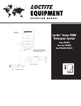
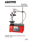
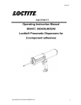
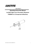
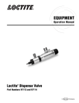
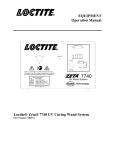
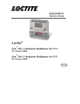
EQUIPMENT Operation Manual Loctite 075 Hot Melt Dispenser 120 Volt Part No. 98033, 230 Volt Part No. 98053 Loctite 075-LT Hot Melt Dispenser 120 Volt Part No. 98034, 230 Volt Part No. 98054 Table of Contents 1 Please observe the following… … … … … … … … … … … … … … … … … … … … … … … 3 1.1 Emphasized Sections… … … … … … … … … … … … … … … … … … … … … … … … … 3 1.2 For Your Safety… … … … … … … … … … … … … … … … … … … … … … … … … … … 3 1.3 Items Supplied… … … … … … … … … … … … … … … … … … … … … … … … … … … ..3 2 Description… … … … … … … … … … … … … … … … … … … … … … … … … … … … ..4 3 Technical Data… … … … … … … … … … … … … … … … … … … … … … … … … … … 4 4 4.1 4.2 Installation… … … … … … … … … … … … … … … … … … … … … … … … … … … … ...5 Exploded View… … … … … … … … … … … … … … … … … … … … … … … … … … … ..6 Parts List… … … … … … … … … … … … … … … … … … … … … … … … … … … … … … 7 5 5.1 5.2 5.3 5.4 Operation… … … … … … … … … … … … … … … … … … … … … … … … … … … … … ..8 Start up… … … … … … … … … … … … … … … … … … … … … … … … … … … … … … ...8 Shut down… … … … … … … … … … … … … … … … … … … … … … … … … … … … … ..9 Temperature Adjustment … … … … … … … … … … … … … … … … … … … … … … … ..9 Application Hints… … … .… … … … … … … … … … … … … … … … … … … … … … … ..9 6 Care and Maintenance… … … … ..… … … … … … … … … … … … … … … … … … … .10 7 Troubleshooting… … … … … … … … … … … … … … … … … … … … … … … … … … ..11 8 8.1 8.2 Documentation… … … … … … … … … … … … … … … … … … … … … … … … … … … .12 Spare Parts … … … … … … … … … … … … … … … … … … … … … … … … … … … … … 12 Accessories… … … … … … … … … … … … … … … … … … … … … … … … … … … … … 13 9 Warranty… … … … … … … … … … … … … … … … … … … … … … … … … … … … … ..14 1 Please Observe the Following 1.1. Emphasized Sections Warning! Refers to safety regulations and required safety measures that protect the operator or other persons from injury. Notice: Gives recommendations for better handling of the machine during operation or adjustment as well as for service activities. Caution! Emphasizes what must be done or avoided so that the unit or other property is not damaged. 1.2 For Your Safety For safe and successful operation of this machine, read these instructions completely. If the instructions are not observed, the manufacturer can assume no responsibility. Observe general safety regulations for the handling of chemicals such as Loctite adhesives and sealants. Observe the manufacturer’s instructions as stated in the Material Safety Data Sheet (MSDS). While under warranty, the machine may be repaired only by an authorized Henkel service representative. Wear heat resistant leather gloves when operating or maintaining a hot tool. Always use care when dispensing hot melt adhesive. Nozzle temperature and adhesive may reach 400F. Avoid skin contact with nozzle or adhesive. If molten adhesive is accidentally deposited on skin, immerse immediately in cold water. DO NOT ATTEMPT TO REMOVE LARGE AMOUNTS OF GLUE FROM SKIN WITHOUT FIRST SECURING PROPER MEDICAL ATTENTION. Check that the surface to be bonded will not melt or be damaged by the temperature of the adhesive. Do not use the tool in damp or wet areas. Always us a properly grounded 120V/230V outlet. Do not remove the grounding prong from the machine electrical plug. A qualified electrician or appliance repair person should perform machine repair. 1.3 Items Supplies Loctite 075 or 075-LT Hot Melt Dispenser Instruction manual Stand-Off Wings Dispenser Stand Speed Loader 2 Description Loctite 075 and the Loctite 075-LT are specifically designed to dispense the full range of Loctite ¾”diameter Maxistick hot melt adhesives. The Loctite 075 hot melt applicator contains two powerful 200W stainless steel cartridge heaters, while the Loctite 075- LT version contains a single 200W stainless steel cartridge heater. Both dispensers feature a totally enclosed heater housing, a sealed thermostatic switch, and thermal fuse protection, providing accuracy in temperature control and excellent reliability. These applicators only take 5 minutes to warm up, yet the Loctite 075 is capable of dispensing up to 9 lbs. of molten hot melt per hour and the Loctite 075-LT can dispense up to 5 pounds/hour. Loctite 075 and the Loctite 075-LT are the highest output, hand-held dispensers in their class. 3 Technical Data Dimensions (L x H x W) approx. 11- 3/4”x 9-1/4”x 1-7/8” Total weight: Operating voltage: 18 oz (500g) Loctite 075: 120V, 3.3 amp, Single Phase 230V, 1.7 amp, Single Phase 120V, 1.7 amp, Single Phase 230V, 0.9 amp, Single Phase Loctite 075-LT: Power consumption: Loctite 075: Loctite 075-LT: 400W 200W Warm up time: Approximately 5 minutes Operating temperature: Loctite 075: Loctite 075-LT: 360F (182C) 250F (121C) Diameter of adhesive inlet: ¾” Extension cable: max. 65ft (20 m) long Wire cross section: at least 16 a.w.g. (1.5 mm2) 4 Installation Notice: Before using the dispenser for the first time: Check it carefully for signs of external damage. If any shipping damage is found DO NOT USE THE TOOL - return it to your supplier immediately. Attach the enclosed stand to the dispenser by locating the slot at the base of the handle grip. Snap the standoff wings into upper vent slots on left and right side of dispenser. These enable the dispenser to be laid on its side without blocking the side vents. To install the speed loader, orient it as shown in the illustration (on next page) and push it down over the magazine cavity. Align the four holes in the Speed Loader with the four tabs on the outside of the magazine chamber and pinch the sides of the Speed Loader to snap the holes over the tabs. To load a hot melt stick into the Speed Loader, hold the dispenser with the nozzle pointed down slightly from the horizontal position. Insert the stick and push it forward until it drops into place. Insert a second stick on top of the first. To drop one of the reserve sticks into the magazine chamber, hold the dispenser horizontally and pull back quickly on the plunger knob. The stick should drop in fully. 4.1 Exploded View 4.2 Parts List ITEM QTY. 46 1 45 1 44 1 43 1 42 1 41 1 40 1 1 39 2 38 1 37 1 36 6 35 2 2 34 1 33 2 32 1 31 1 29 2 27 1 26 1 25 1 1 24 1 23 2 22 1 21 1 20 1 19 1 18 1 17 1 16 6 15 1 14 1 12 1 11 2 10 1 7 2 6 5 4 3 2 1 1 1 1 1 1 1 DESCRIPTION STARLOK WASHER WASHER / SPACER HEATER HOUSING ASSEMBLY FEMALE DISCONNECT TERMINAL RING TERMINAL GROUND WIRE, 10 INCHES LONG HEATER, 120 VOLT, 200 WATT, LOCTITE 075-LT HEATER, 230 VOLT, 200 WATT, LOCTITE 075-LT STAND-OFF WINGS SPEED LOADER, PACKAGE OF 10 DISPENSER STAND, PACKAGE OF 10 SELF TAPPING SCREW HEATER, 120 VOLT, 200 WATT, LOCTITE 075 HEATER, 230 VOLT, 200 WATT, LOCTITE 075 SLOTTED ROUND HEAD SCREW HELICAL SPRING LOCK WASHER #6 THERMAL FUSE ASSEMBLY THERMOSTAT, 360° F / LOCTITE 075, 5 PACK WASHER, INSULATOR LINK PIN TRIGGER CORDSET 3 PRONG UL AUSTRALIAN CORDSET CORD GUARD SELF TAPPING SCREW CORD RETAINER TERMINAL STRIP, 3 POLE TORSION SPRING 65 DEGREES FEED LINK BUSHING COMPRESSION SPRING, .20 X 1.0 X .018 GRIPPING PLATES, DIMPLED THERMOSTAT, 250° / LOCTITE 075-LT, 5 PACK PUSH / PULL KNOB COMPRESSION SPRING, 3/16 X 3/4 X .018 SLIDE SNUBBER ROD / SLIDE PLUNGER ASSEMBLY O-RING, 21.6MM - 2.4MM VT70 O-RING, 21.6MM - 2.4MM VT70 MELT CHAMBER RIGHT HANDLE LEFT HANDLE MELT CHAMBER COLLAR NOZZLE ADAPTER ASSEMBLY NOZZLE .081 ORIFICE See section 8.1 for available spare parts kits. INCLUDED IN PART NUMBER 985309 987907 987907 988776 987907 987907 985307 985753 985309 985309 985306 985749 987907 987907 988776 AVAILABLE PART NO. IZZ020N10 IZZ002N10 982105 EST005N05 985309 985310 985310 985312 985752 985312 985312 985312 985312 985310 985310 985308 985308 985308 EST009N05 985308 985313 985313 985308 987907 985858 985311 985309 985309 987907 ANZ023N01 985225 Operation 5.1 Start Up Caution: The dispenser should have a suitable resting place to facilitate easy operator access and good ventilation around the tool. Good ventilation is necessary to prevent melt down. Caution: For good ventilation, the dispenser should always be positioned when idle so that air is free to circulate around the dispenser. This is particularly important when the ambient temperature is summer-like. Caution: When idle, the nose of the dispenser should not be angled down too sharply or heat from the front of the dispenser will flow over the back of the dispenser. Caution: Always use a dispenser stand. The purpose of the dispenser stand is to hold the dispenser when it is not in use in a position that will facilitate ventilation and cooling of the dispenser. Pull back on the knob at the rear of the dispenser to retract the glue stick plunger. Insert one Maxistick hot melt stick into the magazine cavity of the tool. Use only Loctite Maxistick hot melt sticks. The use of other adhesive brands will void any tool warranty. Plug the power cord into a properly grounded 120V/230V, 15 amp outlet. There is no power switch. Allow 5 minutes for the melt chamber to warm to operating temperature. Do not touch the discharge nozzle as it can cause a serious skin burn. Point the nozzle of the dispenser in a safe direction and actuate the trigger to advance the glue stick to fill the melt chamber. This first stick will only fill the melt chamber. Little or no adhesive will discharge. Stop actuating the trigger when the plunger is fully advanced. This will be indicated when the knob contacts the back of the tool housing. Insert a second hot melt stick and actuate the trigger again. Hot melt should begin to discharge from the nozzle. If the trigger is hard to actuate, allow five minutes for the dispenser to warm to full operating temperature. If the trigger will not operate, check the plunger. If fully advanced, retract it and reload another hot melt stick. 5.2 Shut Down Notice: To prevent hot melt waste, pull the power plug just before the last bonding operation. There is enough residual heat in the melt chamber to dispense one full hot melt stick without power. Easy start-up of a hot melt applicator can be affected by the method of shut down. Step one: pull the plug from the power outlet. Step two: actuate the trigger to dispense at least one half of a hot melt stick. Allow the dispenser to cool down in a proper idle position to facilitate good ventilation. 5.3 Temperature Adjustment The operating temperature of the Loctite 075 and Loctite 075-LT are fixed by a sealed thermostatic switch. The thermostatic set points are factory set and are not user adjustable. The standard operating temperature for the Loctite 075 is 360 F (182 C) and the Loctite 075-LT is 250 F (121 C). 5.4 Application Hints As with all adhesives, performance depends on conditions of use. Suggestions or recommendations contained herein are for guidance only, since actual conditions of use are outside the supplier’s control. Ensure that the surfaces to be bonded are dry, free from dust, grease, and loose particles. Apply adhesive to one surface only. Bring the two surfaces together immediately, quickly making any further adjustments. Hold the joint for 20 - 30 seconds to complete the bond. When bonding dissimilar materials, apply the adhesive to the least heat conductive of the two. On materials that are cold to the touch, a better bond can be made by warming them before applying adhesive. Surplus adhesive can be trimmed using a sharp knife once it has cooled. Should molten adhesive drip onto a smooth or polished surface, allow it to cool completely before removal. Spots or blobs of adhesive are recommended for work pieces having a large surface area, or which are particularly long. Applying the adhesive in wavy lines is recommended for gluing textiles or similar materials. Foam materials, like polystyrene, can be easily bonded to other surfaces. However the adhesive must be applied to the other surfaces, not to the foam. Use only genuine Loctite adhesive sticks to ensure reliable performance. Loctite adhesive sticks are non-toxic and non-flammable. 6 Care and Maintenance Every attempt has been made to make this exceptionally powerful dispenser both reliable and trouble-free. However the following precautions should be noted: When in use, do not lay the dispenser on its side - always place upright using the stand provided. Do not use excessive force on the trigger. Ensure that the dispenser has fully warmed up before use. Keep the nozzle clean to prevent adhesive build-up. This is easily done by wiping the nozzle with clean paper or cloth while the nozzle is still warm. Should “melt down”accidentally occur, switch off the dispenser and allow the adhesive to cool. Gently pull away this excess adhesive, reconnect the power, and allow the dispenser to warm up again. Squeeze the trigger two or three times to advance the hot melt stick, then use the dispenser as normal. Replace the nozzle if worn or damaged. Only replace the nozzle while the tool is still warm. Disconnect the dispenser from the power supply before proceeding, and always use protective gloves. Unscrew the nozzle from the dispenser using either a 1/2” (13 mm) spanner, or the spanner-feature molded into the gun stand. Assemble the replacement nozzle, ensuring that it is securely tightened. Glue “Melt back”and “Melt down” “Melt down”occurs when hot molten adhesive in the glue chamber is forced back between the feed chamber sleeve and the outside surface of the adhesive stick. Once this adhesive cools, it may lock the adhesive stick in the feed chamber sleeve, preventing, or at least restricting, normal extrusion. By far the most likely cause of melt back is not allowing sufficient warm-up time before operating the dispenser (the molten glue in the glue chamber cannot escape forwards because the nozzle is blocked due to being insufficiently warm). In the vast majority of cases the melt back self-clears once the dispenser, having fully reached operating temperature, is operated again. "Melt back" occurs when the rear of the adhesive stick softens to the extent that it is not rigid enough to drive the stick forward without collapsing. As with melt down, the molten adhesive can solidify, potentially locking the stick in the feed chamber sleeve. Melt down is caused by leaving the tool switched on for extended periods of time without operating it. It is recommended that, if the dispenser is to be left standing for forty minutes or more, it should be switched off and only switched back on when preparing to use it again. The Loctite® 075 and 075-LT dispensers are fitted with a Teflon feed chamber sleeve which has non-stick characteristics; this minimizes the effect of any melt back or melt down, should it occur. 7 Troubleshooting Notice: Electrical troubleshooting must be performed by a qualified electrician or appliance repair person. Problem No Heat Possible Cause - No power to dispenser Correction Check main power supply - Faulty thermostat Dispenser is not fully heated - Defective thermostat Check for electrical continuity when cold. Replace if switch is open. Check continuity and replace if open. Check butt splice in TCO circuit and screw terminals for good connection. Isolate and check for discontinuity and replace Allow 5 minutes to reach operating temperature. Change thermostat - - Blown Thermal Cut Out (TCO) - Discontinuity of circuit Inadequate Heat Trigger is hard to actuate Faulty heater - One (of two) faulty heating element - Dispenser is not fully heated - Plunger is bottomed out - High trigger force is required to advance glue stick upon start up. Stick then advances easily. Adhesive leaks back from melt chamber into feed magazine area Adhesive stick diameter is too large - Improper shut down from previous use. - Dispenser is not ventilated properly - Adhesive stick diameter is too small - Thermostat loose Trigger moves but does not advance the plunger reliably. Feed mechanism is worn Isolate and check for discontinuity Allow 5 minutes to reach operating temperature. Retract plunger and load another adhesive stick. Consult adhesive distributor Pull power plug just before last application. Dispense at least half of a glue stick without power to tool. Refer to Installation information Consult adhesive distributor Isolate and check for tightness Replace the plunger assembly 8 Documentation 8.1 Spare Parts 1. Nozzle Adapter Assembly, item 2 2. Speed Loader, item 38, pkg of 10 3. Dispenser Stand, item 37, pkg of 10 4. Heater Assembly Kit, Loctite 075-120V Heater Assembly Kit, Loctite 075-230V Qty 2 –Heaters, item 35 Qty 1 –Female Terminal, item 43 5. Heater Assembly Kit, Loctite 075-LT-120V Heater Assembly Kit, Loctite 075-LT-230V Qty 1 –Heaters, item 35 Qty 1 –Female Terminal, item 43 6. Thermal Fuse (TCO) Assembly Qty 1 - Thermal Fuse (TCO), item 32 7. Thermostat Loctite 075, item 31, pkg of 5 Loctite 075-LT, item 15, pkg of 5 8. Plunger Assembly Kit Qty 1 –Knob, item 14 Qty 6 –Gripping Plates, item 16 Qty 1 –Spring, item 17 Qty 1 –Bushing, item 18 Qty 1 –Plunger Rod Slide, item 10 9. Handle Kit Qty 1 –Right Handle, item 5 Qty 1 –Left Handle, item 4 Qty 6 –Screws, item 36 Qty 1 –Starlok washer, item 46 Qty 1 –Washers Insulator, item 29 Qty 2 –Standoff wings, item 39 10. Trigger Kit Qty 1 –Trigger, item 26 Qty 1 –Feed Link Grip Plate, item 19 Qty 1 –Pin Link, item 27 Qty 1 –Torsion Spring, item 20 11. Melt / Feed Chamber Sleeve Kit Qty 1 –Heater Housing Assembly, item 44 Qty 2 –O-Ring #202-647, item 7 Qty 1 –Helical Spring Lock Washer, item 33 Qty 1 –Ground screw, item 34 Qty 1 –Melt Chamber Collar, item 3 Qty 1 –Ground Wire, item 41 Qty 1 –Ring Terminal, item 42 Qty 1 –Spacer, item 45 Part # ANZ023N01 IZZ020N10 ISZ002N10 985306 985749 985307 985753 988776 EST005N05 EST009N05 985308 985309 985310 987907 8.1 Spare Parts (Continued) 12. U.S. Cordset Kit, 120 volt Australian Cordset Kit, 230 volt Qty 1- Terminal Block, item 21 Qty 1 –Cord Retainer, item 22 Qty 2 –Screws, item 23 Qty 1 –Cord Guard, item 24 Qty 1 –Cordset, 3 prong, item 25 13. Snubber Kit Qty 2 –Snubber Slide, item 11 Qty 1 –Spring, item 12 14. O-Ring, 21.6mm-2.4mm, item 7, pkg of 10 15. Label Kit for 98033 16. Label Kit for 98034 17. Label Kit for 98053 18. Label Kit for 98054 985312 985752 985313 985858 985853 985854 985855 985856 8.2 Accessories Accessories Replacement Nozzle Adapter Assembly Standard Nozzle 1-Hole Kit, Qty 5, 0.080”(2 mm) orifice Nozzle 2-Hole Nozzle 3-Hole Extension Nozzle 0.120”(3 mm) Needle Extension Nozzle 0.050”(1.3 mm) Spreader Extension Nozzle 0.250”(6 mm) “L”Nozzle, overlap carton sealing “T”Nozzle, center flap carton sealing Tool Hanger / Balancer Part Number ANZ023N01 985225 985110 985111 985112 985113 985114 985115 985116 985243 9 Warranty Henkel expressly warrants that all products referred to in this Instruction Manual for Loctite 075 and Loctite 075-LT hot melt dispensers, (hereafter called “Products”), shall be free from defects in materials and workmanship. Liability for Henkel shall be limited, as its option, to replacing those Products which are shown to be defective in either materials or workmanship or to credit the purchaser the amount of the purchase price thereof (plus freight and insurance charges paid therefor by the user). The purchaser’s sole and exclusive remedy for breach of warranty shall be such replacement or credit. A claim of defect in materials or workmanship in any Products shall be allowed only when it is submitted in writing within one month after discovery of the defect or after the time the defect should reasonably have been discovered and in any event, within 1 year after the delivery of the Products to the purchaser. This warranty does not apply to perishable items, such as fuses. No such claim shall be allowed in respect of products which have been neglected or improperly stored, transported, handled, installed, connected, operated, used or maintained. In the event of unauthorized modification of the Products including, where products, parts or attachments for use in connection with the Products are available from Henkel, the use of products, parts or attachments which are not manufactured by Henkel, no claim shall be allowed. No Products shall be returned to Henkel for any reason without prior written approval from Henkel. Products shall be returned freight prepaid, in accordance with instructions from Henkel. NO WARRANTY IS EXTENDED TO ANY EQUIPMENT WHICH HAS BEEN ALTERED, MISUSED, NEGLECTED, OR DAMAGED BY ACCIDENT, OR IF THE SYSTEM IS USED TO DISPENSE ANY LIQUID MATERIAL OTHER THAN HENKEL PRODUCTS. EXCEPT FOR THE EXPRESS WARRANTY CONTAINED IN THIS SECTION, HENKEL MAKES NO WARRANTY OF ANY KIND WHATSOEVER, EXPRESS OR IMPLIED, WITH RESPECT TO THE PRODUCTS. ALL WARRANTIES OF MERCHANTABILITY, FITNESS FOR A PARTICULAR PURPOSE, AND OTHER WARRANTIES OF WHATEVER KIND (INCLUDING AGAINST PATENT OR TRADEMARK INFRINGEMENT) ARE HEREBY DISCLAIMED BY HENKEL AND WAIVED BY THE PURCHASER. THIS SECTION SETS FORTH EXCLUSIVELY ALL OF THE LIABILITY FOR HENKEL TO THE PURCHASER IN CONTRACT, IN TORT OR OTHERWISE IN THE EVENT OF DEFECTIVE PRODUCTS. WITHOUT LIMITATION OF THE FOREGOING, TO THE FULLEST EXTENT POSSIBLE UNDER APPLICABLE LAWS, HENKEL EXPRESSLY DISCLAIMS ANY LIABILITY WHATSOEVER FOR ANY DAMAGES INCURRED DIRECTLY OR INDIRECTLY IN CONNECTION WITH THE SALE OR USE OF, OR OTHERWISE IN CONNECTION WITH, THE PRODUCTS, INCLUDING, WITHOUT LIMITATION, LOSS OF PROFITS AND SPECIAL, INDIRECT OR CONSEQUENTIAL DAMAGES, WHETHER CAUSED BY NEGLIGENCE FROM HENKEL OR OTHERWISE. Henkel Corporation One Henkel Way Rocky Hill, CT 06067-3910 Henkel Canada Corporation 2515 Meadowpine Boulevard Mississauga, Ontario L5N 6C3 Henkel Automotive Technology Center 2455 Featherstone Road Auburn Hills, Michigan 48326 Henkel Ltda. Rua Karl Huller, 136 –Jd. Canhema 09941-410 Diadema/SP, Brazil Loctite is a trademark of Henkel Corporation, U.S.A. © Copyright 2004. Henkel Corporation All rights reserved. Data in this operation manual is subject to change without notice. Manual P/N: 985315, Rev G, 03/11/2013 Henkel Capital, S.A. de C.V. Calzada de la Viga s/n Fracc. Los Laureles Loc. Tulpetlac, C.P. 55090 Ecatepac de Morelos, Edo. de México www.loctite.com