1
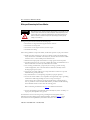
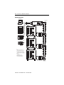
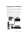
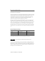
Powermonitor 3000
Master Module
Catalog Numbers 1404-M4, 1404-M5, 1404-M6,
1404-M8
Installation Instructions
Topic
Page
Important User Information
2
About This Publication
3
Safety Considerations
4
About the Power Monitor
5
Catalog Number Explanation
10
Quick Start Guidelines
11
Install the Powermonitor 3000 Unit
12
Product Dimensions
14
Wiring and Connecting the Power Monitor
18
Wiring Diagrams
21
Interpret the Status Indicators
47
Specifications
56
Additional Resources
61
2
Powermonitor 3000 Master Module
Important User Information
Solid state equipment has operational characteristics differing from those of electromechanical equipment.
Safety Guidelines for the Application, Installation and Maintenance of Solid State Controls (Publication
SGI-1.1 available from your local Rockwell Automation sales office or online at
http://literature.rockwellautomation.com) describes some important differences between solid state
equipment and hard-wired electromechanical devices. Because of this difference, and also because of the
wide variety of uses for solid state equipment, all persons responsible for applying this equipment must
satisfy themselves that each intended application of this equipment is acceptable.
In no event will Rockwell Automation, Inc. be responsible or liable for indirect or consequential damages
resulting from the use or application of this equipment.
The examples and diagrams in this manual are included solely for illustrative purposes. Because of the many
variables and requirements associated with any particular installation, Rockwell Automation, Inc. cannot
assume responsibility or liability for actual use based on the examples and diagrams.
No patent liability is assumed by Rockwell Automation, Inc. with respect to use of information, circuits,
equipment, or software described in this manual.
Reproduction of the contents of this manual, in whole or in part, without written permission of Rockwell
Automation, Inc., is prohibited.
Throughout this manual, when necessary, we use notes to make you aware of safety considerations.
WARNING
IMPORTANT
ATTENTION
Identifies information about practices or circumstances that can cause an explosion in
a hazardous environment, which may lead to personal injury or death, property
damage, or economic loss.
Identifies information that is critical for successful application and understanding of
the product.
Identifies information about practices or circumstances that can lead to personal injury
or death, property damage, or economic loss. Attentions help you identify a hazard,
avoid a hazard and recognize the consequences.
SHOCK HAZARD
Labels may be on or inside the equipment, for example, drive or motor, to alert people
that dangerous voltage may be present.
BURN HAZARD
Labels may be on or inside the equipment, for example, drive or motor, to alert people
that surfaces may reach dangerous temperatures.
Publication 1404-IN007F-EN-P - November 2009
Powermonitor 3000 Master Module
3
About This Publication
Except as noted, refer to the Powermonitor 3000 User Manual, publication 1404-UM001, for
detailed information on the topics in this list. These installation instructions do not contain
the following information:
•
•
•
•
•
•
•
Information on metering functionality and measurements
Use of the display module for configuration, monitoring, and commands
Discussion of communication options, functionality, configuration, and operation
Setpoint configuration and operation
Discrete I/O configuration and operation
Data logging including Event Log, Trend Log, Min/Max Log, and Load Factor Log
Advanced features including Oscillography, Harmonic Analysis, and Transient
Detection
• Powermonitor 3000 data tables
• Sample ladder diagrams for communicating with the Powermonitor 3000 unit by
using various communication options
• Display Module Installation Instructions, see publication 1404-IN005
This manual does not provide information on functionality found in the Powermonitor 3000
master module, firmware revision 3.0 and earlier, or Ethernet series A, all firmware revisions,
or Ethernet series B, firmware revision 2.0 earlier. Refer to publications 1404-IN007D-EN-E
and 1404-UM001D-EN-E, available as downloads from
http://literature.rockwellautomation.com.
Terms and Conventions
The following terms and conventions are used in this manual.
Terms and Conventions
Abbreviation
Term
AWG
American Wire Gauge
CSA
Canadian Standards Association
CT
Current transformer
DM
Display module
EMI
Electromagnetic interference
ID
Identification
IEC
International Electrotechnical Commission
NEMA
National Electrical Manufacturers Association
PLC
Programmable logic controller
Publication 1404-IN007F-EN-P - November 2009
4
Powermonitor 3000 Master Module
Terms and Conventions
Abbreviation
Term
PT
Potential transformer (also known as VT in some countries)
RAM
Random access memory
RFI
Radio frequency interference
R I/O
Remote input/output
RMS
Root–mean–square
SLC
Small logic controller
SPDT
Single pole double throw
UL
Underwriters Laboratories
VA
Volt–ampere
VAR
Volt–ampere reactive
CIP
Control and information protocol
NAP
Network access port
Safety Considerations
ATTENTION
Only qualified personnel, following accepted safety procedures, should install, wire, and
service the Powermonitor 3000 unit and its associated components. Before beginning
any work, disconnect all sources of power and verify that they are de-energized and
locked out. Failure to follow these instructions may result in personal injury or death,
property damage, or economic loss.
Never open a current transformer (CT) secondary circuit with primary current applied.
Wiring between the CTs and the Powermonitor 3000 unit should include a shorting
terminal block in the CT secondary circuit. Shorting the secondary with primary current
present allows other connections to be removed if needed. An open CT secondary with
primary current applied produces a hazardous voltage, which can lead to personal injury,
death, property damage, or economic loss.
Publication 1404-IN007F-EN-P - November 2009
Powermonitor 3000 Master Module
IMPORTANT
5
The Powermonitor 3000 unit is not designed for, nor intended for, use as a circuit
protective device. Do not use this equipment in place of a motor overload relay or circuit
protective relay.
The relay output contacts and solid-state KYZ output contacts on the Powermonitor 3000
unit may be used to control other devices through setpoint control or communication. You
can configure the response of these outputs to a communication failure.
Refer to the Powermonitor 3000 User Manual, publication 1404-UM001 for information
on configuring the outputs.
Be sure to evaluate the safety impact of the output configuration on your plant or
process.
ATTENTION
Electrostatic discharge can damage integrated circuits or semiconductors. Follow these
guidelines when you handle the module:
• Touch a grounded object to discharge static potential.
• Wear an approved wrist strap-grounding device.
• Do not open the module or attempt to service internal components.
• Use a static safe workstation, if available.
• Keep the module in its static shield bag when not in use.
About the Power Monitor
The Bulletin 1404 Powermonitor 3000 unit is uniquely designed and developed to meet the
needs of both producers and users of electric power. A power monitor system consists of:
• a master module that provides metering and native RS-485 communication.
• an optional display module for configuration, commands, and data display.
• an optional communication port to serve data to other devices by using a choice of
networks.
• optional external devices and applications that display and use data for reporting,
control, and management of power and energy usage.
Publication 1404-IN007F-EN-P - November 2009
6
Powermonitor 3000 Master Module
The Powermonitor 3000 unit is a microprocessor-based monitoring and control device ideally
suited for a variety of applications including these:
• Load Profiling - Using the configurable trending utility to log power parameters, such
as real power, apparent power, and demand, for analysis of power usage by loads over
time.
• Demand Management - Understanding when and why demand charges occur lets you
make informed decisions that reduce your electrical power costs.
• Cost Allocation - Knowing your actual energy costs promotes manufacturing
efficiencies.
• Distribution System Monitoring - Using power parameters to show power flow,
system topology, and distribution equipment status.
• Emergency Load Shedding - Monitoring power usage to preserve system stability in
the event of sudden utility outage.
• Power System Control - Managing system voltage, harmonic distortion, and power
factor.
The power monitor is a sophisticated modern alternative for traditional electro-mechanical
metering devices. A single power monitor can replace many individual transducers and
meters. The power monitor provides you with easy to understand, accurate information in a
compact economical package.
Powermonitor 3000 Master Module
The master module contains the main microprocessor-based monitoring functions, including
terminations for power system connections, status inputs, control outputs, a native RS-485
communication port, and a port for the display module.
Configuration
Although the power monitor ships from the factory with default settings, you need to
configure it for your particular requirements. You may configure the power monitor by using
the optional display module. Alternately, you may use an external device or application to
write configuration, operational parameters and commands to the master module through its
native or optional communication port.
Refer to the Powermonitor 3000 User Manual, publication 1404-UM001, for additional detail.
Optional external applications that you may use for power monitor configuration include
RSPower, RSPowerPlus, and RSEnergyMetrix software operating on a personal computer.
Contact your local Rockwell Automation sales office or distributor, or visit
http://www.rockwellautomation.com/rockwellsoftware for more information on available
software packages.
Publication 1404-IN007F-EN-P - November 2009
Powermonitor 3000 Master Module
7
Communication
Every Powermonitor 3000 unit comes with a native RS-485 communication port. The native
port is suitable for communicating to devices including:
•
•
•
•
•
PLC-5, SLC 500, and ControlLogix processors.
RSLinx software with DDE/OPC server functionality.
Modbus RTU Master devices.
other third-party devices.
software that you develop.
You may also specify Powermonitor 3000 units with optional communication ports including
the following:
•
•
•
•
•
Serial RS-232
Remote I/O
DeviceNet
EtherNet/IP
ControlNet
A power monitor may be integrated into a programmable controller or computer-based
control and monitoring system by using any of the communication methods listed above.
Publication 1404-IN007F-EN-P - November 2009
8
Powermonitor 3000 Master Module
Master Module with Communication Options
Removable Status Input
Connector
Terminal Blocks
Status Indicators
Display Module Port
RS-485 (Native)
Communication Port
NAP Port
Powermonitor 3000
Powermonitor 3000
Powermonitor
wermonitor 3000
Powermonitor 3000
Powermonitor 3000
ControlNet
Channel A
Optional RS-232
Port
Optional
Remote I/O Port
Optional
DeviceNet
Port
Publication 1404-IN007F-EN-P - November 2009
Optional
Ethernet
10BaseT Port
ControlNet
Channel B
Powermonitor 3000 Master Module
9
Powermonitor 3000 Display Module
The display module is an optional user-interface device. The display module provides the
most economical and simplest method for setting up and configuring the master module for
operation.
The display module has a highly visible, two-line LED display and four operator buttons with
tactile feedback. Use the buttons and display to navigate through a series of menus for
configuration, commands, and data display.
The display module is shipped with a 3 m (10 ft) long, shielded four-pair cable that provides
power and serial communication between the master module and the display module. The
display module fits into a standard ANSI four-inch analog meter cutout for panel mounting.
Only one display module may be connected to a master module, although you may use one
display module to configure and monitor any number of master modules; one at a time.
Display Module
Publication 1404-IN007F-EN-P - November 2009
10
Powermonitor 3000 Master Module
Catalog Number Explanation
The Powermonitor 3000 unit has the following catalog number possibilities.
1404 - M4
Bulletin Number
1404 = Power
Monitoring and
Management
Products
05
Type of Device
Current Inputs
M4 = Master Module with 05 = 5 A
three-phase metering,
Power Supply
setpoints, I/O, and data
logging.
A=
M5 = M4 functionality,
firmware upgradeable to an
M6 or M8.
Communication
Options(1)
000 = None
232 = RS-232 Serial
DNT = DeviceNet
120…240V AC RIO = Remote I/O
ENT = EtherNet/IP
50…60 Hz or
125…250V DC CNT = ControlNet
B = 24V DC
M6 = M5 functionality plus
oscillography, sag/swell
detection, harmonics 1…41
measurement, additional
setpoints and logging,
firmware upgradeable to M8.
M8 = M6 functionality plus
transient capture and
analysis, harmonics
measurement up to 63rd,
Transducer and Energy Meter
modes.
(1)
A - ENT - 02
In addition to Native RS-485 port.
Publication 1404-IN007F-EN-P - November 2009
Revenue
Accuracy Class
Blank = Class 1 or
Class 0.5
02 = Class 0.2
Powermonitor 3000 Master Module
11
Quick Start Guidelines
The Powermonitor 3000 unit may be used in many electric power monitoring and control
systems. Whether your power monitor is a complete power and energy monitor or a
component in a plant- or enterprise-wide energy management system, there are a few basic
steps to follow to make your unit operational.
1. Install your Powermonitor 3000 master module within a suitable enclosure.
Refer to Install the Powermonitor 3000 Unit on page 12.
2. Install your optional display module.
Refer to the Bulletin 1404 Display Module Installation Instructions, publication
1404-IN005.
3. Determine your wiring mode and install wiring between the power monitor and your
power system.
4. Connect control power wiring, preferably from a separate source of control power.
5. If used, connect wiring to the status inputs, Form C control relay, and KYZ solid-state
outputs.
Refer to Wiring and Connecting the Power Monitor on page 18.
6. Configure the potential transformer (PT) and current transformer (CT) ratios to
match those used in your power system connections.
7. Configure the Voltage mode of the power monitor to match your power system
configuration.
8. Configure power monitor communication.
This step varies depending upon the communication option you have selected.
9. Configure the power monitor date and time.
10. Configure other optional performance features, such as setpoint control and data
logging.
Refer to the Powermonitor 3000 User Manual, publication 1404-UM001, for complete
information on configuring and operating your power monitor.
Publication 1404-IN007F-EN-P - November 2009
12
Powermonitor 3000 Master Module
Install the Powermonitor 3000 Unit
Only qualified personnel should install, wire, service, and maintain this equipment. Refer to
and follow the safety guidelines and pay attention to all warnings and notices in these
instructions.
ATTENTION
Electrostatic discharge can damage integrated circuits or semiconductors. Follow these
guidelines when you handle the module:
• Touch a grounded object to discharge static potential.
• Wear an approved wrist strap grounding device.
• Do not open the module or attempt to service internal components.
• Use a static safe work station, if available.
• Keep the module in its static shield bag when not in use.
See Product Dimensions on page 14 for mounting hole dimensions.
Mount the master module with four No. 8-32 UNC or M4 screws with flat washers and lock
washers.
Mounting Considerations
Mount the Powermonitor 3000 master module in a suitable protective enclosure. Select an
enclosure that protects the master module from atmospheric contaminants, such as oil, water,
moisture, dust corrosive vapors and other harmful airborne substances. The enclosure should
also protect against personal contact with energized circuits.
The ambient temperature within the enclosure must remain within the limits listed in the
Specifications, page 56.
Select an enclosure that provides adequate clearance for ventilation and wiring for the power
monitor and other equipment to be installed within the enclosure.
See Product Dimensions on page 14 for dimensions and spacing guidelines for the power
monitor.
When installed within a substation or switchgear lineup, we recommend that the power
monitor be mounted within a low-voltage cubicle, isolated from medium- and high-voltage
circuits.
Publication 1404-IN007F-EN-P - November 2009
Powermonitor 3000 Master Module
13
Mount the master module so that the metal grounding clips on the bottom of the mounting
feet make direct contact with the enclosure mounting panel. If the mounting panel is painted,
scrape or sand the paint down to bare metal. Use star washers to assure good long-term
electrical contact with the mounting panel. Be sure that the mounting panel is properly
connected to a low-impedance earth ground.
Mount the enclosure in a position that allows full access to the master module. Install the
master module with the ventilation slots in the bottom and top of the unit unobstructed to
assure adequate free convection cooling of its internal electronic components.
IMPORTANT
Use caution not to block the ventilation slots of the master module. All wiring and other
obstructions must be a minimum of 50 mm (2.0 in.) from the top and bottom of the unit.
Publication 1404-IN007F-EN-P - November 2009
14
Powermonitor 3000 Master Module
Product Dimensions
Use the dimensions in these drawings when mounting the master module.
Master Module Dimensions
All dimensions are in mm (in.).
14.66
(0.577)
114.30
(4.50)
85.0
(3.346)
Mounting
10.43
(0.411)
4.57 (0.180)
4 Places
5.35
(0.211)
Powermonitor 3000
125.0
(4.921)
Mounting
135.15
(5.321)
114.30
(4.50)
163.17 (6.424)
Used Without
Display Module
184.15 (7.250)
Used With
Display Module
5.60
(0.22)
Publication 1404-IN007F-EN-P - November 2009
203.2 (8.000)
Used With -232
Communication
Options
Powermonitor 3000 Master Module
15
Master Module Spacing
All dimensions are in mm (in.).
215.9 (8.50)
50.8 (2.00)
Minimum
Powermonitor 3000
Powermonitor 3000
215.9 (8.50)
101.6 (4.00)
Powermonitor 3000
Powermonitor 3000
50.8 (2.00)
Minimum
50.8
(2.00)
101.6 (4.00)
50.8
(2.00)
General Notes:
• Recommended spacing provides reasonable wiring clearance and ventilation.
• Maintain approximately 102 mm (4.00 in.) clearance between master modules and other
electrical equipment.
• Do not block cooling vents. Wiring and other obstructions must be 50 mm (2.00 in.) minimum
from top and bottom of unit.
• Mount with ventilation opening in top and bottom to provide optimum free convection cooling.
• Refer to Specifications for ambient temperature requirements.
Publication 1404-IN007F-EN-P - November 2009
16
Powermonitor 3000 Master Module
System Accuracy Considerations
User-supplied potential transformers (PTs) and current transformers (CTs), as well as wiring
from the CTs to the power monitor, may reduce the accuracy of your power monitor system.
The quality of the power monitor’s measurements can be no better than the quality of the
signals presented to its input terminals. It is your responsibility to select transformers that are
adequate for the desired metering accuracy.
ANSI/IEEE C57.13, Requirements for Instrument Transformers, defines three classes of
transformer accuracy: class 1.2, class 0.6, and class 0.3. The application should dictate the
transformer accuracy class used.
PTs and CTs may introduce errors in three areas: ratio errors, phase errors, and bandwidth
errors.
Ratio Errors
The voltage ratio of a PT is the number of primary turns of wire divided by the number of
secondary turns. Manufacturing tolerances may cause the ratio to be slightly different than the
design specifies, causing an error affecting the voltage input to the power monitor.
Likewise, the current ratio of a CT is a function of the ratio of the number of turns of wire on
the primary and secondary. Some error in this ratio is quite common in commercial grade PTs
and CTs.
Other errors include magnetic core losses, winding impedance, and the burden, or load, on
the transformer secondary. The combination of these errors is known as Ratio Error. You
may compensate for Ratio Error, if known, by adjusting the Basic Configuration entries for
PT and CT primary or secondary voltages.
For a PT, the Ratio Error increases as the transformer’s load current increases, so its total load
impedance should be as high as possible. Conversely, a CT’s Ratio Error increases as the
voltage supported by the transformer secondary increases, so its total load impedance,
including the impedance of the wire connecting the CTs to the metering device, should be as
low as possible. This is why 4 mm2 (12 AWG) or larger is usually recommended for wiring
CTs with a 5 A secondary rating.
Publication 1404-IN007F-EN-P - November 2009
Powermonitor 3000 Master Module
17
Phase Error
Phase shift between the primary to secondary signals is another source of inaccuracy
introduced by the user-supplied PTs and CTs. Phase shift is generally not of concern for
simple voltage or current measurements. When these signals are combined, for instance when
calculating line to line voltage or phase power, the effect of phase shift can become
significant. The difference in phase error among different transformers causes measurement
errors. If all the PTs and CTs introduced a 5° phase shift, there would be no error in the
measured quantities. If, on the other hand, the PTs had a phase error of 1° and the CTs had a
phase error of 6°, there would be a 5° phase error in the power calculation. This would show
up as power factor and reactive power (VAR) errors. Phase errors cannot be corrected by
adjusting the power monitor configuration since the errors change based on varying
conditions of the power system.
A typical PT phase error varies from ±1°…±0.25°, depending on the PT’s accuracy class.
Applying higher than rated voltage increases the phase error and may saturate the transformer
and cause even larger errors.
The phase error in a CT increases as its current decreases, and is lowest when the current is
greater than 80% of the CT rating. Because significant phase error can occur when CT
current is less than 20% of rated current, CTs sized for protection do not perform well when
used for metering.
The phase error of both PTs and CTs are also affected by the power factor of the load on the
secondary. For best accuracy, loads should be resistive, with PT loads as high as possible and
CT loads as low as possible.
Bandwidth Error
For fundamental 50 or 60 Hz measurements, bandwidth error has no affect on accuracy.
However, for waveforms with significant harmonic content, the PTs and CTs you supply may
attenuate higher harmonics. Most instrument quality PTs have a flat frequency response out
to 3 kHz, or the 50th harmonic on a 60 Hz system. Current transformers, especially older,
existing units, tend to be less linear, with a flat response only out to 300 Hz, or the fifth (60
Hz) harmonic. Wide-band instrument CTs are available for improved frequency response.
Bandwidth error cannot be corrected by adjusting the power monitor configuration.
In addition, operation of either the PTs or CTs at extremely low frequencies may also cause
saturation and resulting magnitude and phase errors.
For more detailed information on instrument transformer accuracy and power measurement,
refer to Bulletin 1403 Powermonitor II Tutorial, publication 1403-1.0.2.
Publication 1404-IN007F-EN-P - November 2009
18
Powermonitor 3000 Master Module
Wiring and Connecting the Power Monitor
ATTENTION
Only qualified personnel, following accepted safety procedures, should install, wire, and
service the power monitor and its associated components. Before beginning any work,
disconnect all sources of power and verify that they are de-energized and locked out.
Failure to follow these instructions may result in personal injury or death, property
damage, or economic loss.
Wiring of the power monitor includes the following steps:
•
•
•
•
Connection of voltage and current signals from PTs and CTs
Connection of control power
Connection of status inputs and status/control outputs
Communication wiring
Follow these guidelines to help assure reliable, trouble-free operation of your power monitor:
• Install and connect all wiring. Use wire tags to identify connections. Bundle wiring
neatly and maintain a minimum of 50 mm (2.0 in.) clearance from the master module
ventilation slots to avoid a buildup of heat within the unit.
• Furnish and install properly-selected fuses for voltage signals and control power.
• Use 600V wiring rated at 75 °C (167 °F) or higher. We strongly recommend the use of
flame-retardant wire rated VW-1 by Underwriters Laboratories.
• Use a shorting terminal block (you provide) for CT wiring, to permit servicing
connected equipment, such as the Powermonitor 3000 master module, without
de-energizing the power system.
• Use ring lugs or locking spade lugs for voltage and current connections to provide
additional wiring security and safety.
• Pay careful attention to correct phasing and polarity for proper operation.
• Connect the master module to a low-impedance earth ground by using its grounding
terminal and a dedicated grounding wire at least as large as the largest
current-carrying wire connected to the master module. Keep grounding wiring as
short as possible. To obtain maximum EMI immunity, the master module mounting
feet should make electrical contact with the mounting panel.
Refer to Mounting Considerations on page 12 for additional information.
• Connect all equipment ground terminals (master module, PT, and CT secondary) to a
single point, low-impedance earth ground.
For information on wire sizes and types for grounding electrical equipment, refer to
Industrial Automation Wiring and Grounding Guidelines, publication 1770-4.1, or the
National Electrical Code published by National Fire Protection Association (NFPA).
Publication 1404-IN007F-EN-P - November 2009
Powermonitor 3000 Master Module
19
Wiring the Master Module
Observe all wire lug sizes and screw torques for terminal blocks wire sizes and screw torques.
Refer to Specifications on page 56.
Voltage and Current Inputs
The following sections give information on the selection of PTs and CTs.
Voltage Input and PT Selection
The power monitor is designed to connect directly to a power system rated up to 600V
line-to-line (347V line-to-neutral). Higher system voltages require the use of user-supplied
PTs. Typical secondary voltage on a PT is 120V AC. Select the PT primary voltage to match
the nominal voltage of your power system.
Connect short circuit protection, that you supply, between the power system and the power
monitor. If PTs are used, install short circuit protection on the high-voltage side of the PTs.
Current Inputs and Current Transformer (CT) Selection
The current input on the power monitor is designed for a 5 A nominal current signal.
User-supplied CTs are required to connect your power system to the input of the power
monitor. Select the CT primary current to match the nominal current of your power system.
ATTENTION
Never open a current-transformer secondary circuit with primary current applied. Wiring
between the CTs and the power monitor should include a shorting terminal block in the
CT secondary circuit. Shorting the secondary with primary current present allows other
connections to be removed if needed. An open CT secondary with primary current applied
produces a hazardous voltage, which can lead to personal injury, death, property
damage, or economic loss.
Publication 1404-IN007F-EN-P - November 2009
20
Powermonitor 3000 Master Module
The shorting terminal block should be located adjacent to the Powermonitor 3000 master
module so that it is readily accessible should service be needed. Use 2.5 mm2 (14 AWG) wire
for the short run between the power monitor and the shorting terminal block. Use wiring of 4
mm2 (12 AWG) or larger between the shorting terminal block and the CT so that the
additional load of the wiring does not overload the CT and reduce its accuracy.
IMPORTANT
You may install either two or three CTs for any of the Delta or Open Delta wiring or
voltage modes.
Refer to the wiring diagrams on pages 28, 30, and 33 for wiring of a two CT configuration.
Whether there are two or three CTs in a circuit does not affect the voltage wiring.
Refer to the Powermonitor 3000 Unit User Manual, publication 1404-UM001.
Do not install fuses or other overcurrent protection in the secondary circuit of a CT.
Refer to System Accuracy Considerations on page 16 for guidelines on PT and CT selection.
Refer to Specifications on page 56 for information on voltage isolation levels and wire
termination recommendations.
The wiring diagrams depict wiring methods for a variety of power system configurations. You
need to configure your power monitor to match the power system configuration for correct
operation.
Refer to the Powermonitor 3000 Unit User Manual, publication 1404-UM001, for detailed
instructions on unit configuration.
Publication 1404-IN007F-EN-P - November 2009
Powermonitor 3000 Master Module
21
Wiring Diagrams
Single-phase Direct Connection Wiring Diagram
(Systems < 600V Nominal L-L)
Voltage Mode = Single Phase
Line
L1
L2
N
Fuse
Fuse
Powermonitor 3000
Master
Module
Customer-supplied
CT Shorting Switch or
Test Block
R14
R11
R12
N/C
I1I2I3I4-
Y
Z
N/C
V1
I1+
V2
I2+
V3
I3+
N
I4+
R14 R11 R12 Y
Load
L1
(+)
L2
(-)
GRD
K
K
Z
Customer
Chassis
Ground
Publication 1404-IN007F-EN-P - November 2009
22
Powermonitor 3000 Master Module
Single-phase with PTs Wiring Diagram
Line
L1
L2
Voltage Mode = Single Phase
N
Fuse
Fuse
Customer-supplied
CT Shorting Switch or
Test Block
R14
R11
R12
N/C
I1I2I3I4-
Y
Customer
Chassis
Ground
Publication 1404-IN007F-EN-P - November 2009
L1
(+)
L2
(-)
GRD
K
Z
N/C
V1
I1+
V2
I2+
V3
I3+
N
I4+
R14 R11 R12
Load
Powermonitor 3000
Master
Module
Y
K
Z
Powermonitor 3000 Master Module
23
Three-phase Four-wire Wye Direct Connect Wiring Diagram
(Systems < 600V Nominal L-L)
Line
L1
L2
Voltage Mode = Wye
L3
N
Fuse
Fuse
Fuse
Customer-supplied
CT Shorting Switch or
Test Block
R14
R11
R12
N/C
I1I2I3I4R14 R11
Load
Powermonitor 3000
Master
Module
Y
L1
(+)
L2
(-)
GRD
K
Z
N/C
V1
I1+
V2
I2+
V3
I3+
N
I4+
R12
Y
K
Z
Customer
Chassis
Ground
Publication 1404-IN007F-EN-P - November 2009
24
Powermonitor 3000 Master Module
Three-phase Four-wire with PT’s Wiring Diagram
Line
L1
L2
L3
Voltage Mode = Wye
N
Fuse
Fuse
Fuse
Customer-supplied
CT Shorting Switch or
Test Block
R14
R11
R12
N/C
I1I2I3I4-
Y
Customer
Chassis
Ground
Publication 1404-IN007F-EN-P - November 2009
L1
(+)
L2
(-)
GRD
K
Z
N/C
V1
I1+
V2
I2+
V3
I3+
N
I4+
R14 R11 R12
Load
Powermonitor 3000
Master
Module
Y
K
Z
Powermonitor 3000 Master Module
25
Three-phase Three-wire Grounded Wye Direct Connection Wiring Diagram
(Systems < 600V Nominal L-L)
Line
L1
L2
Voltage Mode = Wye
L3
Fuse
Fuse
Fuse
Customer-supplied
CT Shorting Switch or
Test Block
R14
R11
R12
N/C
I1I2I3I4-
Y
L1
(+)
L2
(-)
GRD
K
Z
N/C
V1
I1+
V2
I2+
V3
I3+
N
I4+
R14 R11 R12
Load
Powermonitor 3000
Master
Module
Y
K
Z
Customer
Chassis
Ground
Publication 1404-IN007F-EN-P - November 2009
26
Powermonitor 3000 Master Module
Three-phase Three-wire Grounded Wye with PTs Wiring Diagram
Line
L1
L2
Voltage Mode = Wye
L3
Fuse
Fuse
Fuse
Customer-supplied
CT Shorting Switch or
Test Block
R14
R11
R12
N/C
I1I2I3I4-
Y
Customer
Chassis
Ground
Publication 1404-IN007F-EN-P - November 2009
L1
(+)
L2
(-)
GRD
K
Z
N/C
V1
I1+
V2
I2+
V3
I3+
N
I4+
R14 R11 R12
Load
Powermonitor 3000
Master
Module
Y
K
Z
Powermonitor 3000 Master Module
27
Three-phase Three-wire Delta with Three PTs and Three CTs Wiring Diagram
Line
Voltage Mode = Delta 3 CT
L1
L2
L3
Fuse
Fuse
Fuse
Customer-supplied
CT Shorting Switch or
Test Block
R14
R11
R12
N/C
I1I2I3I4-
Y
L1
(+)
L2
(-)
GRD
K
Z
N/C
V1
I1+
V2
I2+
V3
I3+
N
I4+
R14 R11 R12
Load
Powermonitor 3000
Master
Module
Y
K
Z
Customer
Chassis
Ground
Publication 1404-IN007F-EN-P - November 2009
28
Powermonitor 3000 Master Module
Three-phase Three-wire Delta with Three PTs and Two CTs Wiring Diagram
Voltage Mode = Delta 2 CT
Line
L1
L2
L3
Fuse
Fuse
Fuse
Customer-supplied
CT Shorting Switch or
Test Block
R14
R11
R12
N/C
I1I2I3I4-
Y
Customer
Chassis
Ground
Publication 1404-IN007F-EN-P - November 2009
L1
(+)
L2
(-)
GRD
K
Z
N/C
V1
I1+
V2
I2+
V3
I3+
N
I4+
R14 R11 R12
Load
Powermonitor 3000
Master
Module
Y
K
Z
Powermonitor 3000 Master Module
29
Three-phase Three-wire Open Delta with Two PTs and Three CTs Wiring
Diagram
Voltage Mode = Open Delta 3 CT
Line
L1
L2
L3
Fuse
Fuse
Customer-supplied
CT Shorting Switch or
Test Block
R14
R11
R12
N/C
I1I2I3I4-
Y
L1
(+)
L2
(-)
GRD
K
Z
N/C
V1
I1+
V2
I2+
V3
I3+
N
I4+
R14 R11 R12
Load
Powermonitor 3000
Master
Module
Y
K
Z
Customer
Chassis
Ground
Publication 1404-IN007F-EN-P - November 2009
30
Powermonitor 3000 Master Module
Three-phase Three-wire Open Delta with Two PTs and Two CTs Wiring Diagram
Voltage Mode = Open Delta 2 CT
Line
L1
L2
L3
Fuse
Fuse
Customer-supplied
CT Shorting Switch or
Test Block
R14
R11
R12
N/C
I1I2I3I4-
Y
Customer
Chassis
Ground
Publication 1404-IN007F-EN-P - November 2009
L1
(+)
L2
(-)
GRD
K
Z
N/C
V1
I1+
V2
I2+
V3
I3+
N
I4+
R14 R11 R12
Load
Powermonitor 3000
Master
Module
Y
K
Z
Powermonitor 3000 Master Module
31
Three-phase Three-wire Grounded L2(B) Phase Open Delta Direct Connect with
Three CTs Wiring Diagram (Systems < 600V Nominal L-L)
Voltage Mode = Open Delta 3 CT
Line
L1
L3
Distribution
Ground
Fuse
Fuse
Voltage must not
exceed 347V L-L
(otherwise, step down
transformers are required).
Customer-supplied
CT Shorting Switch or
Test Block
R14
R11
R12
N/C
I1I2I3I4-
Powermonitor 3000
Master
Module
Y
L1
(+)
L2
(-)
GRD
K
Z
N/C
V1
I1+
V2
I2+
V3
I3+
N
I4+
R14 R11 R12
Y
K
Z
Customer
Chassis
Ground
Load
Publication 1404-IN007F-EN-P - November 2009
32
Powermonitor 3000 Master Module
Three-phase Three-wire Delta Direct Connect with Three CTs Wiring Diagram
(Systems < 600V Nominal L-L)
Voltage Mode = Direct Delta 3 CT
Line
L1
L2
L3
Fuse
Fuse
Fuse
Customer-supplied
CT Shorting Switch or
Test Block
R14
R11
R12
N/C
I1I2I3I4-
Y
Load
Publication 1404-IN007F-EN-P - November 2009
L1
(+)
L2
(-)
GRD
K
Z
N/C
V1
I1+
V2
I2+
V3
I3+
N
I4+
R14 R11 R12
Customer
Chassis
Ground
Powermonitor 3000
Master
Module
Y
K
Z
Powermonitor 3000 Master Module
33
Three-phase Three-wire Delta Direct Connect with Two CTs Wiring Diagram
(Systems < 600V Nominal L-L)
Line
L1
L2
Voltage Mode = Direct Delta 2 CT
L3
Fuse
Fuse
Fuse
Customer-supplied
CT Shorting Switch or
Test Block
R14
R11
R12
N/C
I1I2I3I4-
Y
L1
(+)
L2
(-)
GRD
K
Z
N/C
V1
I1+
V2
I2+
V3
I3+
N
I4+
R14 R11 R12
Load
Powermonitor 3000
Master
Module
Y
K
Z
Customer
Chassis
Ground
Publication 1404-IN007F-EN-P - November 2009
34
Powermonitor 3000 Master Module
Control Power
The power monitor draws a nominal 15VA control power. Catalog numbers
1404-MxxxA-xxx require nominal control power of 120…240V AC or
125…250V DC. The power supply is self-scaling. Catalog numbers 1404-MxxxB-xxx require
nominal control power of 24V DC.
L1
N/L2
Local
Frame
Ground
Powermonitor 3000
Master Module
Y
R14
K
L1
(+)
Z
L2
(-)
R11
R12
S1
S2
SCOM
GRD
N/C
N/C
V1
I1+
I1-
V2
DISPLAY
MODULE
I2+
I2-
V3
I3+
N
I3-
SHLD
I4+
I4-
RS-485
R14
R11 R12
Y
K
Z
Refer to Specifications on page 56 for acceptable control-voltage ranges and wiring
termination information.
We strongly recommend that you use a separate source of control power from the power
system being monitored. For applications where power system information is critical,
consider the use of a user-supplied uninterruptible power supply so that the power monitor
continues to operate during power system events such as significant sags, swells, and transient
disturbances.
You are required to connect your power-monitor control power through user-supplied
disconnecting means and overcurrent protection. We recommend a 1 A slow-blow fuse.
Status Inputs
ATTENTION
Do not apply an external voltage to a Status Input. These inputs have an internal source
and are intended for dry contact input only. Applying a voltage may damage the
associated input or internal power supply.
Publication 1404-IN007F-EN-P - November 2009
Powermonitor 3000 Master Module
35
All Status Inputs are common to an internal 24V DC source on the SCOM terminal. Status
input terminals S1 and S2 are positive polarity and SCOM is negative polarity.
For optimal EMC performance, we recommend wiring the status inputs by using shielded
cable, Belden 8771 or equivalent, with the cable shield grounded at both ends where possible.
Status Input Connections
N.O.
Contact
Powermonitor 3000
Master Module
Y
R14
K
L1
(+)
Z
L2
(-)
R11
R12
N/C
SCOM
GRD
V1
I1+
V2
DISPLAY
MODULE
I2+
V3
I3+
N
I3-
SHLD
+
I4+
I4R14
N.O.
Contact
S2
N/C
I1I2-
S1
R11 R12
Y
K
Z
RS-485
Applied resistance versus status state
• Condition 1 is 3.5 kW or less = ON
• Condition 2 is 5.5 kW or greater = Off
Isolation Voltage is 500V status input to case and 500V status input to internal digital
circuitry.
TIP
Status Input S2 can be configured for external demand pulse input. See the
Powermonitor 3000 User Manual, publication 1404-UM001, for more information.
Relay and KYZ Outputs
Control Relay Connections on page 36 shows the Form C relay output connections and an
example of customer wiring to a supply voltage and two loads. Terminal R11 is the common
connection, R14 is the normally-open connection, and R12 is the normally-closed
connection. You must supply the wetting voltage and overcurrent protection for the circuit
connected to the relay output.
Refer to Specifications on page 56 for further information.
Publication 1404-IN007F-EN-P - November 2009
36
Powermonitor 3000 Master Module
The KYZ output is a solid-state relay designed for low-current switching and long life. Its
normal application is to provide a pulse based on energy usage (or one of five other
parameters) to an external pulse accumulator. Terminal K is common, Y is normally-open,
and Z is normally-closed.
Refer to the Powermonitor 3000 Unit User Manual, publication 1404-UM001, for further
information on the application and operation of relay and KYZ outputs.
Control Relay Connections
L1
10A
Fuse
N
Powermonitor 3000
Master Module
Y
R14
K
L1
(+)
Z
L2
(-)
R11
R12
N/C
GRD
V1
I1+
V2
DISPLAY
MODULE
I2+
V3
I3+
N
I3I4+
I4R14
S2
N/C
I1I2-
S1
SCOM
R11 R12
Y
K
Z
SHLD
+
RS-485
Communication Wiring
Methods for connecting communication wiring vary from option to option. This section
provides guidelines for installing dependable communication wiring for your power monitor
system.
ATTENTION
IMPORTANT
You must supply and install special high-level isolation when the possibility of high
ground potential differences exists. This may occur when communicating with a unit
connected to a power ground mat. Failure to install such isolation may lead to personal
injury or death, property damage, or economic loss.
You need to configure communication for each communication option.
Refer to the Powermonitor 3000 Unit User Manual, publication 1404-UM001, for detailed
communication configuration instructions.
Publication 1404-IN007F-EN-P - November 2009
Powermonitor 3000 Master Module
37
Native RS-485 Communication Wiring
The RS-485 communication standard supports multi-drop communication among as many as
32 stations or nodes.
The RS-485 port is also used for master module firmware upgrades in the field.
RS-485 communication wiring should be installed in a daisy-chain configuration. We
recommend that you use Belden 9841 two-conductor shielded cable or equivalent. The
maximum cable length is 1219 m (4000 ft). Use of a star or bridging topology is not
recommended and will result in signal distortion unless impedance is matched for each spur
(star topology) or network (bridge topology).
If required, install suitable terminating resistors at the ends of the daisy-chain cable. For
RS-485, install a 150 Ω, 1/4 W terminating resistor (refer to the wiring diagram). Note that
some RS-485 conversion devices are equipped with internal terminating resistors. Contact the
manufacturer of the converter for additional information.
At one end of each cable segment, connect the cable shield to the SHLD terminal of the
master module RS-485 port or the converter. The SHLD connection provides a
low-impedance ground for high-frequency noise while attenuating DC or line-frequency
signals.
The RS-485 port in the master module presents a standard load impedance to the RS-485
network, allowing the standard 32 nodes on a network.
Configuration options for the native RS-485 port include the protocol, device address, and
the data rate. Defaults are:
• auto-detect protocol.
• device address = the Device ID assigned at the factory in the range 1…254.
• communication rate = 9600 bps.
Use of RS-232 to RS-485 Converter
You need a user-supplied RS-232 to RS-485 converter for communication between the power
monitor native RS-485 port and an external device such as a computer or programmable
controller RS-232 port. Examples include:
• B&B Electronics, Inc. part number 485SD9TB (DB-9 connection).
• Allen-Bradley catalog number 1761-NET-AIC.
Publication 1404-IN007F-EN-P - November 2009
38
Powermonitor 3000 Master Module
RS-485 Connections
IBM Compatible
Personal Computer
Shield Connection
(See Note 4)
External
RS-232C to RS-485
Converter
(See Note 3)
SHLD
A
B
150 Ω
Terminating
Resistor
(See Note 2)
Or
PLC Processor
Powermonitor 3000 Device #1
SHLD
Or
SLC Processor
RS-485
_
+
Powermonitor 3000 Device #2
Or
ControlLogix Processor
SHLD
RS-485
_
+
Notes:
1) Three-device network shown. Up to 31 DF1
Slave Devices can be connected to a
DF1 Master without the use of a repeater.
2) Terminating resistors may be required for
networks with long distances or high noise
environments. Consult the RS-232 to RS-485
converter manufacturer for more informaiton.
3) Examples:
B&B Electronics
Part Number 485SD9TB (DB9)
Allen-Bradley Cat. No. 1761-NET-AIC
4) Shields should be connected at
one end only to avoid ground loops.
Powermonitor 3000 Device #3 (Last)
SHLD
RS-485
_
+
150 Ω
Terminating
Resistor
(See Note 2)
Publication 1404-IN007F-EN-P - November 2009
Powermonitor 3000 Master Module
39
Optional RS-232 Communication
Powermonitor 3000 units with a catalog number ending in -232 are equipped with an RS-232
serial communication port in addition to the native RS-485 port. The RS-232 communication
standard supports point-to-point communication among two stations or nodes. You must
select either optional RS-232 communication or native RS-485 communication. The two
ports do not operate at the same time.
The optional RS-232 communication port is a data communication equipment (DCE) type
device. It requires a straight-through RS-232 cable to connect with personal computers,
programmable controller serial ports, and other data terminal equipment (DTE) devices. It
requires a crossover cable for connection to a modem or other DCE devices. No terminating
resistor is required.
The maximum cable length is 15.24 m (50.0 ft). Refer to the following wiring diagrams for
cable pinout information for constructing your own cable using DB-9 and/or DB-25
connectors.
Connecting Powermonitor 3000 Unit to Computer Communication Port
Powermonitor 3000
DB9 Female
1
5
6
9
RS-232
IBM Compatible
Personal Computer
1
–
TXD
2
Output
RXD
3
Input
No connect
No connect
4
–
GND
5
Ground
DSR (See Note 2)
6
Output
RTS (See Note 1)
7
CTS (See Note 1)
8
No connect
9
Input
Output
–
(See Note 3)
Notes:
1) Required only if you have
enabled hardware handshaking.
2) Internally pulled active in this DCE
device - function not supported.
3) Straight-through RS-232 cable required.
Or PLC Processor
Powermonitor 3000 Device
6
9
6
13
1
25
14
2
2
3
RXD
3
3
2
TXD
CTS (See Note 1)
8
8
5
CTS (See Note 1)
RTS (See Note 1)
7
7
4
RTS (See Note 1)
GND
5
5
7
GND
TXD
Or ControlLogix Processor
1
5
1
5
9
PLC-5 Ch 0 - DB-25 Male
IBM Personal Computer - DB-25 Female
DB9 Female
DB9 Female
Or SLC Processor
SLC 500 Ch 0
IBM Personal Computer
RXD
Publication 1404-IN007F-EN-P - November 2009
40
Powermonitor 3000 Master Module
Optional Remote I/O Communication
Powermonitor 3000 units with a catalog number ending in -RIO are equipped with a remote
I/O port in addition to the native RS-485 port. Allen-Bradley remote I/O is a robust, widely
used industrial data network that uses twinaxial cable as its physical media. The power
monitor emulates a logical quarter rack and supports both polled I/O and block transfer
communication. The remote I/O port and the native RS-485 port may be used
simultaneously, although overall data throughput may be reduced.
Remote I/O communication wiring should be installed in a daisy-chain configuration. We
recommend that you use Belden 9463 twinaxial cable or equivalent. The maximum cable
length is shown in the Remote I/O Communication Rates table and varies with the data rate.
Use of a star or bridging topology is not recommended and will result in signal distortion
unless impendance is matched for each spur (star topology) or network (bridge topology).
Be sure that all devices on your remote I/O network are capable of operation at the desired
communication rate. Certain legacy devices may not support a 230.4 Kbps communication
rate.
Remote I/O Communication Rates
Communication Rate
Distance, Max
Terminating Resistor
57.6 Kbps
3048 m (10,000 ft)
150 Ω, 1/4 W
115.2 Kbps
1542 m (5000 ft)
150 Ω, 1/4 W
230.4 Kbps
762 m (2500 ft)
84 Ω, 1/4 W
Install suitable terminating resistors at the ends of the remote I/O network.
TIP
Some remote I/O devices are equipped with internal terminating resistors.
At each end of each cable segment, connect the cable shields to the SHLD terminal of the
remote I/O port connector. The SHLD connection provides a low-impedance ground for
high-frequency noise while attenuating DC or line-frequency signals. We recommend that you
follow the standard blue/shield/clear color scheme for remote I/O to differentiate it from
Data Highway Plus (clear/shield/blue) cables.
Publication 1404-IN007F-EN-P - November 2009
Powermonitor 3000 Master Module
41
Configuration options for optional remote I/O communication include the logical rack
address and module group (the power monitor is always one-quarter rack), and data rate.
Defaults are rack 1, group 0, 57.6 Kbps.
Refer to the Powermonitor 3000 Unit User Manual, publication 1404-UM001.
Refer to the note at the beginning of Communication Wiring on page 36.
Connecting Powermonitor 3000 Unit to Remote I/O Scanner
IBM Compatible
Personal Computer
With R I/O
Interface Card
82 Ω
Terminating
Resistor
(See Note 2)
Blue
Shield
1
SHLD
Or
PLC Processor/
PLC R I/O Scanner
Clear
2
Powermonitor 3000 Device #1
2
SHLD
R I/O
1
Or
SLC R I/O Scanner
Powermonitor 3000 Device #2
2
Or
ControlLogix R I/O Scanner
SHLD
R I/O
Notes:
1) Three-device network portrayed.
Up to 32 slave devices can
be connected per master
R I/O channel.
2) Terminating Resistors
must be connected
to each end of the
R I/O network. Omit the
terminating resistors
if the devices already
are equipped with internal
terminating resistors.
1
Powermonitor 3000 Device #3 (Last)
2
SHLD
R I/O
1
82 Ω
Terminating
Resistor
(See Note 2)
Publication 1404-IN007F-EN-P - November 2009
42
Powermonitor 3000 Master Module
Optional DeviceNet Communication
Powermonitor 3000 units with a catalog number ending in -DNT are equipped with a
DeviceNet port in addition to the native RS-485 port. The DeviceNet network is an
open-standard, multi-vendor, industrial device data network that uses a variety of physical
media. The DeviceNet network also provides 24V DC power to devices connected to the
network. The DeviceNet port and the native RS-485 port may be used simultaneously,
although overall data throughput may be reduced.
For detailed DeviceNet system installation information, including cable lengths, the
placement of terminating resistors, power supplies, and other media components, refer to the
DeviceNet Cable System Planning and Installation Manual,
publication DNET-UM072.
Refer to the note at the beginning of Communication Wiring on page 36.
Install suitable terminating resistors at the ends of the DeviceNet cable.
TIP
IMPORTANT
Some DeviceNet devices are equipped with internal terminating resistors.
You must install and wire a suitable 24V DC power supply to the V+ and V- conductors in
the DeviceNet cable. The power monitor consumes less than 100 mA from the DeviceNet
24V DC supply.
Configuration options for optional DeviceNet communication include the node address
(MAC ID) and data rate. Defaults are node 63 and 125 Kbps.
Refer to the Powermonitor 3000 Unit User Manual, publication 1404-UM001.
DeviceNet Terminal Block Wiring Connections
Terminal
Signal
Function
Color
1
COM (V-)
Common
Black
2
CAN_L
Signal Low
Blue
3
SHIELD
Shield
Uninsulated
4
CAN_H
Signal High
White
5
VDC+ (V+)
Power Supply
Red
Publication 1404-IN007F-EN-P - November 2009
Powermonitor 3000 Master Module
43
Connecting Powermonitor 3000 to Other DeviceNet Devices
VPowermonitor 3000 Device
CAN_L
SHLD
CAN_H
121 Ω
Terminating
Resistor
(See Note 2)
V+
IBM Compatible Personal Computer With
1784 PCDPCMCIA Interface Card
Or
1770-KFD Interface Box
VCAN_L
SHLD
CAN_H
Or
PLC With
1771-SDN Scanner
V+
Notes:
1) Example network protrayed.
For detailed DeviceNet
installations, including
cable requirements, refer to
the DeviceNet Cable System
Planning and Installation Manual,
publication DNET-UM072.
2) Terminating Resistors
must be connected
to each end of the
DeviceNet network. Omit the
terminating resistors
if the devices already
are equipped with internal
terminating resistors.
VCAN_L
SHLD
CAN_H
V+
Or
SLC With
1747-SDN Scanner
VCAN_L
121 Ω
Terminating
Resistor
(See Note 2)
SHLD
CAN_H
V+
Or Other DeviceNet
Scanner Devices
DeviceNet
24V DC
Power Supply
+
-
Optional Ethernet Communication
Powermonitor 3000 units with catalog numbers ending in -ENT are equipped with an
industry standard Ethernet 10/100baseT port.
The power monitor is designed to connect easily to industry-standard Ethernet hubs and
switches using standard UTP (unshielded twisted-pair) cables with RJ-45 connectors. The
Ethernet Wiring Connections table shows the cable and connector pin assignments and
Powermonitor 3000 Ethernet Network Example shows a typical star network topology.
Publication 1404-IN007F-EN-P - November 2009
44
Powermonitor 3000 Master Module
Ethernet Wiring Connections
Terminal
Signal
Function
1
TX+
TX+
2
TX-
TX-
3
RX+
RX+
RX-
RX-
4
5
6
7
8
Powermonitor 3000 Ethernet Network Example
Ethernet Switch
LAN
SLC 500 Controller
Powermonitor 3000
Master Module #1
Personal Computer with
RSLinx and
RSPower 32 or
RSEnergyMetrix
Software
PLC-5 Controller
Powermonitor 3000
Master Module #2
ControlLogix Controller
Publication 1404-IN007F-EN-P - November 2009
Powermonitor 3000 Master Module
45
Refer to the note at the beginning of Communication Wiring on page 36.
Configuration options for optional Ethernet communication include the IP (Internet
Protocol) address, subnet mask, default gateway IP address, and protocol.
Defaults are:
• IP address: 192.168.254.xxx where xxx is the Device ID assigned at the factory in the
range 1…247.
• subnet mask: 255.255.0.0.
• default gateway IP address: 128.1.1.1.
• protocol: CSP (PCCC) and CIP (EtherNet/IP network).
Optional ControlNet Communication
Powermonitor 3000 units with catalog numbers ending in -CNT are equipped with a
ControlNet communication interface. The ControlNet power monitor can be connected in a
single media or redundant media network. An example of a ControlNet network using
redundant media is shown here.
Powermonitor 3000 Unit ControlNet Network Example
Powermonitor 3000 Device
ControlNet
Node
1756-CNBR
(in 1756-A4 chassis)
ControlNet Link
Redundant Media
(optional)
Powermonitor 3000 Device
ControlNet
Node
Publication 1404-IN007F-EN-P - November 2009
46
Powermonitor 3000 Master Module
Refer to the following documentation for ControlNet network wiring requirements and
general ControlNet information:
• ControlNet Coax Media Planning and Installation Guide,
publication CNET-IN002
• ControlNet Coax Tap Installation Instructions, publication 1786-IN007
Connecting a Programming Terminal to the Network by Using a 1786-CP Cable
To connect a programming terminal to the network using a 1786-CP cable, you have the
following options:
• Using a 1784-KTC, 1784-KTCx, or 1784-PCC communication card and a 1786-CP
cable
Powermonitor 3000 Device
1784-KTC, KTCx,
PCIC, or PCC Card
1786-CP Cable
ControlNet Link
• Using a 1770-KFC communication interface, a serial or parallel connection, and a
1786-CP cable
Powermonitor 3000 Device
1786-CP
Cable
1770-KFC
Serial or Parallel
Connections
ControlNet Link
Publication 1404-IN007F-EN-P - November 2009
Powermonitor 3000 Master Module
47
The 1786-CP cable can be plugged into any ControlNet product’s NAP to provide
programming capability on the ControlNet network. A programming terminal connected
through this cable is counted as a node and must have a unique network address.
ATTENTION
Use a 1786-CP cable when connecting a programming terminal to the network through
NAPs. Using a commercially available RJ-style cable could result in network failure.
Interpret the Status Indicators
The power monitor is equipped with six bi-color status indicators.
The three status indicators on the left display the same information on power monitor
modules with any communication option including native RS-485 communication only. The
three status indicators on the right have different labels and different indications depending
on the communication option selected, as shown in these charts.
Publication 1404-IN007F-EN-P - November 2009
48
Powermonitor 3000 Master Module
Powermonitor 3000 Status Indicators
Powermonitor 3000
MODULE
STATUS
RX
RS-485
TX
All Powermonitor 3000 Models Status Indicators
Indicator
Status
Description
Module Status
Off
Control power is off or insufficient.
Steady red
Major fault; internal self-test has failed. If a power cycle
does not correct the problem, call customer support.
Steady green
Power monitor is operating normally.
Off
The RS-485 bus is idle; no active data is present.
Flashing green
Active data is present on the RS-485 bus.
Off
Power monitor is not transmitting data onto the RS-485
bus.
Flashing green
Power monitor is transmitting data onto the RS-485 bus.
RS-485 RX
RS-485 TX
RS-485 Status Indicators
Powermonitor 3000
F1
F2
F3
Native RS-485 Communication Only (catalog numbers ending in -000)
Indicator
Status
Description
F1
Off
Not used.
F2
Off
Not used.
F3
Off
Not used.
Publication 1404-IN007F-EN-P - November 2009
Powermonitor 3000 Master Module
49
RS-232 Status Indicators
Powermonitor 3000
F1
RX
TX
}
RS-232
RS-232 Optional Communication (catalog numbers ending in -232)
Indicator
Status
Description
F1
Off
Not used.
RS-232 RX
Off
The RS-232 bus is idle; no active data is present.
Flashing green
Power monitor is receiving data.
RS-232 TX
Off
The power monitor is not transmitting any data onto the
RS-232 bus.
Flashing green
The power monitor is transmitting data.
Remote I/O Status Indicators
Powermonitor 3000
F1
F2
R I/O
Remote I/O Optional Communication (catalog numbers ending in -RIO)
Indicator
Status
Description
F1
Off
Not used.
F2
Off
Not used.
R I/O
Off
Remote I/O communication has not been established.
Flashing green
Remote I/O communication has been established but there
are errors.
Steady green
Remote I/O communication has been established.
Publication 1404-IN007F-EN-P - November 2009
50
Powermonitor 3000 Master Module
DeviceNet Status Indicators
Powermonitor 3000
F1
F2
NETWORK
STATUS
DeviceNet Optional Communication (catalog numbers ending in -DNT)
Indicator
Status
Description
F1
Off
Not used.
F2
Off
Not used.
Network Status
Off
Power is off or the power monitor is not online.
Flashing green
Network status is OK, no connections established.
Steady green
Network status is OK, connections established.
Flashing red
Recoverable communication failure; port is restarting.
Steady red
Nonrecoverable communication error; check wiring and
configuration parameters.
EtherNet/IP Status Indicators
LNK
Powermonitor
wermonitor 3000
ACT
F1
F2
NETWORK
STATUS
EtherNet/IP Optional Communication (catalog numbers ending in -ENT)
Indicator
Status
Description
LNK
Off
No valid physical EtherNet connection.
Steady green
Valid physical EtherNet connection.
ACT
Strobing or solid yellow
Power monitor transmitting onto the EtherNet/IP network.
F1
Off
Not used.
Publication 1404-IN007F-EN-P - November 2009
Powermonitor 3000 Master Module
51
EtherNet/IP Optional Communication (catalog numbers ending in -ENT)
Indicator
Status
Description
F2
Off
Not used.
Network Status
Off
No power.
Flashing green
No established connections.
Steady green
Connected; has at least one established connection.
Flashing red
Connection timeout; one or more connections to this device
has timed-out.
Steady red
Duplicate IP; the IP address assigned to this device is
already in use.
Flashing green/red
Selftest; this device is performing a power-up self-test.
ControlNet Status Indicators
Powermonitor 3000
CHAN A
CHAN B
NETWORK
STATUS
ControlNet Optional Communication (catalog numbers ending in -ENT)
Indicator
Status
Chan A and Chan B Off
Steady red
Status
Description
No power or channel disabled.
Faulted unit.
Alternating red/green
Self-test.
Alternating red/off
Incorrect node configuration.
Steady green
Normal operation.
Flashing green/off
Temporary errors or node is not configured to go online.
Flashing red/off
Media fault or no other nodes present on network.
Flashing red/green
Incorrect network configuration.
Off
Normal operation.
Flashing green
Communication card power-up self-test.
Publication 1404-IN007F-EN-P - November 2009
52
Powermonitor 3000 Master Module
Access Self-test and Diagnostic Data
You can access valuable diagnostic information by using the optional display module.
1. Connect the display module to the master module by using the display module cable.
2. Using the four control keys, navigate through the menus to Display - Status and press
Enter.
The display module then displays the following data. Use the up and down arrow keys
to step through the status data.
Display Module Status
Display
Description
CAT NO
The unit catalog number and series revision letter.
ACC CLASS
Displays the revenue-meter accuracy class.
WIN NO
The unit’s unique Warranty Identification Number (needed for service and
optional firmware enhancements).
HW REV
Displays details of the digital board, analog board, and ASIC revisions.
FRN MASTER
MODULE
Shows the master-module firmware revision.
DEVICE ID
Shows the units device ID number assigned at the factory. This number is also
used in the default address for native RS-485, and optional RS-232 and
EtherNet/IP communication.
SELFTEST
STATUS
Displays a status code bitfield as a hex number. A non-zero value indicates an
anomaly.
CODE FLASH
Indicates the health of the flash-memory code area.
RAM
Indicates the health of the random access memory.
DATA FLASH
Indicates the health of the flash-memory data area.
NVRAM
Indicates the health of the super-cap backed nonvolatile random-access memory.
D ACQ
Indicates the data-acquisition system health.
W DOG
Indicates the system watchdog-timer status.
CLOCK
Indicates the health of the real-time clock.
COMM
Displays the firmware revision of the optional communication card (if applicable).
COMM
Displays the optional communication-card type.
COMM
Displays the optional communication-status bitfield as a hex number (0000 hex is
normal for -232 and -RIO units, and 9001 hex is normal for -DNT and -ENT units).
Publication 1404-IN007F-EN-P - November 2009
Powermonitor 3000 Master Module
53
Display Module Status
Display
Description
DMSTA
Displays the display-module status bitfield as a hex number. A non-zero value
may indicate an anomaly, although a non-zero value may appear if a display
module is connected to an operating master module.
DM FRN
Indicates the display-module firmware revision.
MM/DD/YYYY
Displays the current date.
HH/MM/SS
Displays the current time.
RELAY
Shows the status of the Form 4C relay.
KYZ
Shows the status of the KYZ output.
S1 STATUS
Shows the status of Status Input 1.
S1 COUNT
Shows the accumulated value of Status Input 1 counter, since last cleared.
S2 STATUS
Shows the status of Status Input 2, since last cleared.
S2 COUNT
Shows the accumulated value of Status Input 2 counter.
OUTWD
Displays the output word bitfield as a hex number.
Refer to the Powermonitor 3000 Unit User Manual, publication 1404-UM001, for
information on using the display module.
Calibration
To meet general operating requirements, regular recalibration is not necessary.
For special customer requirements, contact your local Rockwell Automation representative
for calibration or service information.
Publication 1404-IN007F-EN-P - November 2009
54
Powermonitor 3000 Master Module
Cleaning Instructions
ATTENTION
Electrostatic discharge can damage integrated circuits or semiconductors. Follow these
guidelines when you handle the module:
• Touch a grounded object to discharge static potential.
• Wear an approved wrist strap grounding device.
• Do not open the module or attempt to service internal components.
• Use a static safe work station, if available.
• Keep the module in its static shield bag when not in use.
• Disconnect and lock out all power sources and short all current transformer
secondaries before servicing. Failure to comply with these precautions can lead to
personal injury or death, property damage, or economic loss.
1. Turn off all electrical power supplied to the master module.
2. Clean the master module with a dry, anti-static, lint-free cloth.
a. Remove all dust and any obstructions from the cooling air vents on the upper,
lower, and ends of the module.
b. Be sure that the nameplate is clean and in good condition.
3. Clean the display module with a dry, anti-static, lint-free cloth.
a. Remove all dust and foreign materials from the exterior of the module.
b. Be sure that the graphic front-panel overlay and back nameplate are clean and in
good condition.
Publication 1404-IN007F-EN-P - November 2009
Powermonitor 3000 Master Module
55
Field Service Considerations
If the power monitor requires servicing, contact your nearest Rockwell Automation sales
office. To minimize your inconvenience, the initial installation should be performed in a
manner that makes removal easy.
• A CT shorting block should be provided to allow the Powermonitor 3000
master-module current inputs to be disconnected without making the user-supplied
CTs an open circuit. The shorting block should be wired to prevent any effect on the
external protective relays.
• All wiring should be routed to allow easy maintenance at connections to the
power-monitor terminal strips and the power monitor itself.
ATTENTION
Never open a current transformer (CT) secondary circuit with primary current applied.
Wiring between the CTs and the power monitor should include a shorting terminal block
in the CT secondary circuit. Shorting the secondary with primary current present allows
other connections to be removed, if needed. An open CT secondary with primary current
applied produces a hazardous voltage, which can lead to personal injury, death, property
damage, or economic loss.
Firmware Upgrades
Power monitor firmware upgrades are of two types. Service upgrades are those that occur
from time-to-time to improve operation and resolve issues. Product upgrades are optional
firmware enhancements that you may purchase to convert your 1404-M5 master module to
an 1404-M6 or 1404-M8, or your 1404-M6 to an 1404-M8.
Service upgrades may be available at no charge. Contact your local Rockwell Automation
representative for information or visit the Internet at http://www.ab.com/PEMS.
Product upgrades are available for purchase. Contact your Rockwell Automation
representative for additional information.
Master module firmware upgrades (of either type) are performed by using the native RS-485
communication port. Firmware upgrades may be performed without removing the power
monitor from its installation. An RS-485 to RS-232 converter is required to connect between
the power monitor and your personal computer communication port. Cycling power to the
power monitor may be required to complete the firmware upgrade.
Factory-installed Communication Cards
The RS-485 communication is integral to the master module and cannot be removed. Adding
or changing a second communication card to a power monitor must be done at the factory
and is not field upgradeable.
Publication 1404-IN007F-EN-P - November 2009
56
Powermonitor 3000 Master Module
Specifications
Measurement Accuracy and Range
Powermonitor 3000 Master Module - 1404-M4, 1404-M5, 1404-M6, 1404-M8
Parameter
Accuracy in % of Full Scale at 25 °C (77 °F) 50/60 Hz Unity
Power Facator
Nominal/Range
1404-M4
1404-M5
1404-M6
1404-M8
Voltage sense
inputs: V1, V2,
V3
±0.2%
±0.05%
±0.05%
±0.05%
347V/15…399V L-N
rms
600V/26…691V L-L
rms
Current sense
input: I1, I2, I3, I4
±0.2%
±0.05%
±0.05%
±0.05%
5 A/50 mA…10.6 A
rms
Frequency
±0.05 Hz
±0.05 Hz
±0.05 Hz
±0.05 Hz
50 or 60 Hz/40…75 Hz
Power functions:
kW, kVA, kVAR
Demand
functions: kW,
kVA
Energy functions:
kWH, kVAH
ANSI C12.16
and
EN 61036 Class
1 Accuracy
ANSI C12.20
and
EN 60687
Class 0.5
Accuracy
(Class 0.2 is
also
available)
ANSI C12.20
and
EN 60687
Class 0.5
Accuracy
(Class 0.2 is
also
available)
ANSI
C12.20 and
EN 60687
Class 0.5
Accuracy
(Class 0.2
is also
available)
Metering update
rates
65…90 ms
55…80 ms
55…85 ms
50…100
ms
Input and Output Ratings
Attribute
Value
Control power 1404-xxxxA-xxx
102…240V AC 47…63 Hz or
106…250V DC
(0.2 A max loading)
Control power 1404-xxxxB-xxx
18…50V DC (15V A max loading)
Voltage sense inputs: V1, V2, V3
Input impedance: 1 MΩ min, 399V AC max; V1, V2 and V3 to N
Publication 1404-IN007F-EN-P - November 2009
Powermonitor 3000 Master Module
57
Input and Output Ratings
Attribute
Value
Current sense inputs: I1, I2, I3, I4
Overload withstand: 15 A continuous, 200 A for 1 s
Burden: 0.05VA
Impedance: 0.002 Ω
Max crest factor at 5 A: 3
Starting current: 5 mA
Status inputs
Contact closure (internal 24V DC)
Control relay
KYZ output
(1) ANSI C37.90-1989 trip duty
(1) Solid state KYZ - 80 mA at 240…300V DC
Control Relay(1)
Rating
50/60 Hz AC rms
DC
Resistive load switching, max
10 A at 250V
(2500VA)
10 A at 30V and 0.25 A at 250V
Load switching, min
10 mA at 24V
10 mA at 24V
UL 508, CSA 22.2, IEC rating class
B300
Q300
Make values, max (inductive load)
30 A at 120V
15 A at 240V
(3600VA)
0.55 A at 125V
0.27 A at 250V
(69VA)
Break values, max (inductive load)
3 A at 120V
1.5 A at 240V
(360VA)
0.55 A at 125V
0.27 A at 250V
(69VA)
Motor load switching, max
1/3 HP at 125V
1/2 HP at 250V
(1)
Meets ANSI/IEEE C37.90-1989 standards for trip duty.
Input and Output Ratings(1)
Attribute
Number of Operations
Mechanical
5 x 10⁶
Electrical
1 x 10⁵
(1)
Meets ANSI/IEEE C37.90-1989 standards for trip duty.
Publication 1404-IN007F-EN-P - November 2009
58
Powermonitor 3000 Master Module
Technical Specifications - 1404-M4, 1404-M5, 1404-M6, 1404-M8
Attribute
Dielectric withstand
Terminal blocks
1404-M4, 1404-M5, 1404-M6,
1404-M8
Control power
2000V
Voltage inputs
2000V
Current inputs
2000V
Status inputs
500V
Control relays
1600V
Power supply and voltage input
terminals
4 mm2 (12 AWG) max,
1.02 N•m (9 lb•in) torque,
75 °C (167 °F) or higher copper
wire only
Relay, KYZ outputs, current input
2.5 mm2 (14 AWG) max,
1.18 N•m (10.4 lb•in) torque,
75 °C (167 °F) or higher copper
wire only
terminals(1)
Status inputs, RS485
2.5 mm2 (14 AWG) max,
0.56 N•m (5 lb•in) torque
RIO, DNT (when present)
2.5 mm2 (14 AWG) max,
0.56 N•m (5 lb•in) torque
Temperature, operating
-20…60 °C (-40…140 °F) cat. no. 1404-DM, 1404-Mxxxx-000,
1404-Mxxxx-DNT
0…55 °C (32 …131 °F) cat. no. 1404-Mxxxx-232, -RIO, -ENT, -CNT
Temperature, storage
-40…85 °C (-40…185 °F)
Humidity
5…95%, noncondensing
Vibration
10…500 Hz: 2 g operational (±0.012 in.)
Shock
1/2 sine pulse, 11 ms duration: 30 g operational and nonoperational
(1)
Recommended ring lug: AMP part # 320634.
Publication 1404-IN007F-EN-P - November 2009
Powermonitor 3000 Master Module
59
Product Approvals
Powermonitor 3000 units have the following approvals and certifications.
EtherNet/IP Conformance Testing
All products equipped with an EtherNet/IP communication port bear the mark shown
below. This mark indicates the power monitor has been tested at an Open Device Vendor
Association (ODVA) independent test lab and has passed the EtherNet/IP conformance test.
This test provides a level of assurance that the power monitor interoperates with other
conformance tested EtherNet/IP devices (including devices from other vendors). Two
representative devices from the Powermonitor 3000 EtherNet/IP family of devices, the
1404-M405A-ENT/B and the 1404-M805A-ENT/B modules, have been tested by ODVA
using EtherNet/IP Conformance Test version A2.8. The ODVA website
(http://www.odva.org) maintains a list of products that have passed the conformance test at
one of their test labs.
ControlNet Conformance Testing
All products equipped with a ControlNet communication port bear the mark shown below.
This mark indicates the power monitor has been tested at a ControlNet International (CI)
independent test lab and has passed the ControlNet conformance test. This test provides a
level of assurance that the power monitor interoperates with other conformance tested
ControlNet devices (including devices from other vendors). Two representative device from
the Powermonitor 3000 ControlNet family of devices, the 1404-M405A-CNT/A and the
1404-M805A-CNT/A modules, have been tested by CI using ControlNet Conformance Test
version 12. The CI website (http://www.ControlNet.org) maintains a list of products that
have passed the conformance test at one of their test labs.
UL/CUL
UL 508 listed, File E96956, for Industrial Control Equipment and CUL Certified.
Publication 1404-IN007F-EN-P - November 2009
60
Powermonitor 3000 Master Module
CE Certification
If this product bears the CE marking, it is approved for installation within the European
Union and EEA regions. It has been designed to meet the following directives.
EMC Directive
This product is tested to meet Council Directive 89/336/EEC Electromagnetic
Compatibility (EMC) and the following standards, in whole, documented in a technical
construction file:
• EN 50081-2 - Generic Emission Standard, Part 2 - Industrial Environment
• EN 50082-2 - Generic Immunity Standard, Part 2 - Industrial Environment
This product is intended for use in an industrial environment.
Low Voltage Directive
This product is tested to meet Council Directive 73/23/EEC Low Voltage, by applying the
safety requirements of IEC 1010-1, Safety Requirements for Electrical Equipment for
Measurement, Control, and Laboratory Use.
This equipment is classified as an open style device. Open style devices must be provided with
environmental and safety protection by proper mounting in enclosures designed for specific
application conditions. See NEMA Standards publication 250 and IEC publication 529, as
applicable, for explanations of the degrees of protection provided by different types of
enclosure.
International Standard IEC 529 / NEMA / UL 508 Degree of Protection
The Powermonitor 3000 master module is rated as IP10 degree of protection per
International Standard IEC 529. It is considered an open device per NEMA and UL 508.
The Powermonitor 3000 display module is rated as IP65 degree of protection per
International Standard IEC 529. It is rated as Type 4 (Indoor) per NEMA and UL 508.
Follow the recommended installation guidelines to maintain these ratings.
ANSI/IEEE Tested
Meets or exceeds the Surge Withstand Capability (SWC) C37.90.1 - 1989 for protective relays
and relay systems on all power connection circuit terminations.
Publication 1404-IN007F-EN-P - November 2009
Powermonitor 3000 Master Module
61
Additional Resources
Refer to these power and energy management documents for more information.
.
For this information
Refer to Publication
Powermonitor 3000 User Manual, publication
1404-UM001
Provides details about configuring and using the
master module.
Powermonitor 3000 Display Module Installation
Instructions, publication 1404-IN005
Provides details about how to mount and wire the
display module.
Bulletin 1403 Powermonitor II Tutorial,
publication 1403-1.0.2
Provides details about instrument transformer
accuracy and power measurement
You can view or download publications at http://www.rockwellautomation.com/literature.
To order paper copies of technical documentation, contact your local Rockwell Automation
distributor or sales representative.
Documentation Feedback
Your comments will help us serve your documentation needs better. If you have any
suggestions on how to improve this document, complete this form, publication RA-DU002,
available at http://www.rockwellautomation.com/literature/.
Publication 1404-IN007F-EN-P - November 2009
62
Powermonitor 3000 Master Module
Notes:
Publication 1404-IN007F-EN-P - November 2009
Powermonitor 3000 Master Module
63
Notes:
Publication 1404-IN007F-EN-P - November 2009
Rockwell Automation Support
Rockwell Automation provides technical information on the Web to assist you in using its
products. At http://www.rockwellautomation.com/support/, you can find technical manuals,
a knowledge base of FAQs, technical and application notes, sample code and links to software
service packs, and a MySupport feature that you can customize to make the best use of these
tools.
For an additional level of technical phone support for installation, configuration, and
troubleshooting, we offer TechConnect support programs. For more information, contact
your local distributor or Rockwell Automation representative, or visit
http://www.rockwellautomation.com/support/.
Installation Assistance
If you experience an anomoly within the first 24 hours of installation, review the information
that's contained in this manual.
You can contact Customer Support for initial help in getting your product up and running.
United States or
Canada
1.440.646.3434
Outside United
States or Canada
Use the Worldwide Locator at
http://www.rockwellautomation.com/support/americas/phone_en.html, or
contact your local Rockwell Automation representative.
New Product Satisfaction Return
Rockwell Automation tests all of its products to ensure that they are fully operational when
shipped from the manufacturing facility. However, if your product is not functioning and
needs to be returned, follow these procedures.
United States
Contact your distributor. You must provide a Customer Support case number
(call the phone number above to obtain one) to your distributor in order to
complete the return process.
Outside United
States
Please contact your local Rockwell Automation representative for the return
procedure.
Rockwell Automation, Allen-Bradley, Rockwell Software, SLC, SLC 500, PLC, PLC-5, ControlLogix, Powermonitor 3000, Powermonitor II,
Data Highway Plus, TechConnect, RSPower, RSPowerPlus, RSEnergyMetrix, and RSLinx are trademarks of Rockwell Automation, Inc.
Trademarks not belonging to Rockwell Automation are property of their respective companies.
Publication 1404-IN007F-EN-P - November 2009
Supersedes Publication 1404-IN007E-EN-P - October 2006
PN-55982
Copyright © 2009 Rockwell Automation, Inc. All rights reserved. Printed in the U.S.A.